EP4516688A1 - Blank and method of folding a blank - Google Patents
Blank and method of folding a blank Download PDFInfo
- Publication number
- EP4516688A1 EP4516688A1 EP24195933.7A EP24195933A EP4516688A1 EP 4516688 A1 EP4516688 A1 EP 4516688A1 EP 24195933 A EP24195933 A EP 24195933A EP 4516688 A1 EP4516688 A1 EP 4516688A1
- Authority
- EP
- European Patent Office
- Prior art keywords
- panel
- blank
- package
- straddle
- folded
- Prior art date
- Legal status (The legal status is an assumption and is not a legal conclusion. Google has not performed a legal analysis and makes no representation as to the accuracy of the status listed.)
- Granted
Links
Images


Classifications
-
- B—PERFORMING OPERATIONS; TRANSPORTING
- B65—CONVEYING; PACKING; STORING; HANDLING THIN OR FILAMENTARY MATERIAL
- B65D—CONTAINERS FOR STORAGE OR TRANSPORT OF ARTICLES OR MATERIALS, e.g. BAGS, BARRELS, BOTTLES, BOXES, CANS, CARTONS, CRATES, DRUMS, JARS, TANKS, HOPPERS, FORWARDING CONTAINERS; ACCESSORIES, CLOSURES, OR FITTINGS THEREFOR; PACKAGING ELEMENTS; PACKAGES
- B65D5/00—Rigid or semi-rigid containers of polygonal cross-section, e.g. boxes, cartons or trays, formed by folding or erecting one or more blanks made of paper
- B65D5/02—Rigid or semi-rigid containers of polygonal cross-section, e.g. boxes, cartons or trays, formed by folding or erecting one or more blanks made of paper by folding or erecting a single blank to form a tubular body with or without subsequent folding operations, or the addition of separate elements, to close the ends of the body
-
- B—PERFORMING OPERATIONS; TRANSPORTING
- B65—CONVEYING; PACKING; STORING; HANDLING THIN OR FILAMENTARY MATERIAL
- B65D—CONTAINERS FOR STORAGE OR TRANSPORT OF ARTICLES OR MATERIALS, e.g. BAGS, BARRELS, BOTTLES, BOXES, CANS, CARTONS, CRATES, DRUMS, JARS, TANKS, HOPPERS, FORWARDING CONTAINERS; ACCESSORIES, CLOSURES, OR FITTINGS THEREFOR; PACKAGING ELEMENTS; PACKAGES
- B65D5/00—Rigid or semi-rigid containers of polygonal cross-section, e.g. boxes, cartons or trays, formed by folding or erecting one or more blanks made of paper
- B65D5/42—Details of containers or of foldable or erectable container blanks
- B65D5/44—Integral, inserted or attached portions forming internal or external fittings
- B65D5/50—Internal supporting or protecting elements for contents
-
- B—PERFORMING OPERATIONS; TRANSPORTING
- B65—CONVEYING; PACKING; STORING; HANDLING THIN OR FILAMENTARY MATERIAL
- B65D—CONTAINERS FOR STORAGE OR TRANSPORT OF ARTICLES OR MATERIALS, e.g. BAGS, BARRELS, BOTTLES, BOXES, CANS, CARTONS, CRATES, DRUMS, JARS, TANKS, HOPPERS, FORWARDING CONTAINERS; ACCESSORIES, CLOSURES, OR FITTINGS THEREFOR; PACKAGING ELEMENTS; PACKAGES
- B65D5/00—Rigid or semi-rigid containers of polygonal cross-section, e.g. boxes, cartons or trays, formed by folding or erecting one or more blanks made of paper
- B65D5/42—Details of containers or of foldable or erectable container blanks
-
- B—PERFORMING OPERATIONS; TRANSPORTING
- B65—CONVEYING; PACKING; STORING; HANDLING THIN OR FILAMENTARY MATERIAL
- B65D—CONTAINERS FOR STORAGE OR TRANSPORT OF ARTICLES OR MATERIALS, e.g. BAGS, BARRELS, BOTTLES, BOXES, CANS, CARTONS, CRATES, DRUMS, JARS, TANKS, HOPPERS, FORWARDING CONTAINERS; ACCESSORIES, CLOSURES, OR FITTINGS THEREFOR; PACKAGING ELEMENTS; PACKAGES
- B65D5/00—Rigid or semi-rigid containers of polygonal cross-section, e.g. boxes, cartons or trays, formed by folding or erecting one or more blanks made of paper
- B65D5/42—Details of containers or of foldable or erectable container blanks
- B65D5/44—Integral, inserted or attached portions forming internal or external fittings
- B65D5/50—Internal supporting or protecting elements for contents
- B65D5/5028—Elements formed separately from the container body
- B65D5/5035—Paper elements
- B65D5/5059—Paper panels presenting one or more openings or recesses in wich at least a part of the contents are located
- B65D5/5061—Paper panels presenting one or more openings or recesses in wich at least a part of the contents are located the openings or recesses being located in different panels of a single blank
-
- B—PERFORMING OPERATIONS; TRANSPORTING
- B65—CONVEYING; PACKING; STORING; HANDLING THIN OR FILAMENTARY MATERIAL
- B65D—CONTAINERS FOR STORAGE OR TRANSPORT OF ARTICLES OR MATERIALS, e.g. BAGS, BARRELS, BOTTLES, BOXES, CANS, CARTONS, CRATES, DRUMS, JARS, TANKS, HOPPERS, FORWARDING CONTAINERS; ACCESSORIES, CLOSURES, OR FITTINGS THEREFOR; PACKAGING ELEMENTS; PACKAGES
- B65D77/00—Packages formed by enclosing articles or materials in preformed containers, e.g. boxes, cartons, sacks or bags
- B65D77/04—Articles or materials enclosed in two or more containers disposed one within another
- B65D77/0413—Articles or materials enclosed in two or more containers disposed one within another the inner and outer containers being rigid or semi-rigid and the outer container being of polygonal cross-section formed by folding or erecting one or more blanks, e.g. carton
- B65D77/0426—Articles or materials enclosed in two or more containers disposed one within another the inner and outer containers being rigid or semi-rigid and the outer container being of polygonal cross-section formed by folding or erecting one or more blanks, e.g. carton the inner container being a bottle, canister or like hollow container
Definitions
- the invention relates to a blank configured to be folded into a package or into an insert to be positioned in a package.
- the invention also relates to a method of folding a blank into a package or into an insert.
- the package should e.g., be designed such that it makes efficient use of material, is easy to prepare for use, is space efficient during transport and storage, and provides a strong structure during use.
- the package is easy to form. This is especially important when the blank is to be folded manually since it is typically desirous that it only requires one person to perform the task. Thus, it is often desirable that the package should be formed in a manner that requires a limited number of folding operations, and/or folding operations which are easy to perform.
- a base material with low environmental impact such as paperboard
- a minimum of such material and to minimize the need for adhesives or staples, or the like, or at least provide it in a manner making it easy to separate from the base material.
- a blank configured to be folded into a package or into an insert to be positioned in a package, the blank comprising:
- the blank may be folded into a package, or into an insert intended to be placed within a separate package.
- the package or insert formed by the blank may be used for transporting and/or storing a bottle, e.g., a wine bottle.
- the front straddle panel is foldably connected to, and intermediately located between, the inner front wall panel and the rear straddle panel.
- the front straddle panel When the blank is folded into a package or an insert, the front straddle panel is configured to bridge a distance between the inner front wall panel and the rear wall panel.
- the first internal recess of the front straddle panel and the rear straddle panel is configured such that a neck of a bottle, placed upon the bottom panel, is allowed to extend into the opening of the first internal recess.
- internal refers to the recess being located at an inner portion of the blank and preferably also being fully surrounded by uninterrupted material. It may be noted that internal does not necessarily mean that the recess is at an inner portion or fully surrounded by uninterrupted material of the panel it is said to be located in.
- a lower end of the first internal recess is located at a distance from a fold line between the inner front wall panel and the front straddle panel. That is, this end of the recess may be said to be internal both with respect to the blank and with respect to the front straddle panel.
- the upper end of the first internal recess is located in flush with a fold line between the rear straddle panel and the top panel.
- this end of the recess may be said to be internal with respect to the blank.
- the upper end of the recess may be withdrawn downwardly from the fold line between the rear straddle panel and the top panel and in such a case also this end of the recess may be said to be internal both with respect to the blank and with respect to the rear straddle panel.
- An advantage of having the front straddle panel extending from the front of the package, where it is foldably connected to the inner front wall panel, to the rear part of the package, where the rear straddle panel abuts the rear wall panel, is that it provides structural integrity to the package when folded.
- the front straddle panel prevents the inner front wall panel and the rear wall panel from being displaced towards the packed bottle and it maintains a gap between the bottle and the adjacent walls.
- a bottle most often is narrower at an upper part around the neck, compared to the lower parts of the bottle, it is advantageous to have a package designed such that the void within the package, around the neck of the bottle, is partly filled with panels extending transversally to the inner front wall panel and the rear wall panel and that abuts said walls of the package.
- a design will provide the package with a rigid structure.
- the rear straddle panel together with the top panel, the top front panel, and the top straddle panel provides a stronger structure to the upper part of the package. This is advantageous since it provides a package which is less prone to be compromised if the upper part of the package is exposed to external shocks.
- the blank may be made out of paper, such as paperboard or cardboard, or the blank may be made out of another material that has a low environmental impact.
- the blank is preferably made of a paper-based material, e.g., a material based on paper or paperboard.
- Paper-based material may provide a lightweight package. Paper-based material may be produced in an environmentally friendly manner and may be recycled in a simple manner. Paper-based material may provide a blank that is easy to transport and handle before the blank is formed to the package. It may be noted that the blank may be made of other materials. It may be noted that the blank as a whole may be made of paper-based material. It may be noted that the blank need not to be made of the same material through-out.
- the blank may be made of a paper-based material coated or laminated with a polymer-based coating, such as a thermoplastic material, on one or both sides thereof.
- a polymer-based coating such as a thermoplastic material
- Such coating may be heat-sealable and/or provide a desired tightness, i.e., barrier properties, such as being waterproof, water resistant, grease proof, grease resistant, food safe, etc.
- the blank may further comprise a second bottom panel and a rear buffer panel,
- the second bottom panel may be folded relative to the first bottom panel such that it extends over an interior surface of the first bottom panel.
- the bottle will preferably be placed upon the second bottom panel.
- the second bottom panel may be folded such that it forms an outer bottom of the package, thus, the bottle will be placed upon the first bottom panel.
- An advantage of having two bottom panels placed on top of each other, creating a double layered bottom of the package, is that the package may provide a better protection to the packed bottle, and it creates a more rigid bottom of the package.
- the second bottom panel may have approximately the same length and width as the first bottom panel, or the second bottom panel may have a smaller length and/or width than the first bottom panel.
- the rear buffer panel may, in an alternative embodiment when being directly foldably connected to the second bottom panel, be connected to the transversally extending side of the second bottom panel such that it extends longitudinally alongside the rear wall panel as seen in a flat-laid state of the blank.
- the second bottom panel is, as described above, folded relative to the first bottom panel and the rear buffer panel is laid flat over the rear wall panel.
- the rear buffer panel and the rear wall panel may together be folded upwardly relative to the bottom panels and forms, at least partially, a double layered rear wall.
- the rear buffer panel may have an extension in the longitudinal direction which is preferably 60%, more preferably 70%, even more preferably 80% of the longitudinal extension of the rear wall panel.
- An advantage of having a rear buffer panel forming an additional rear wall is that the package is reinforced on the backside which allows for a better protection of the bottle, and it provides the package with a stronger structure and better stability.
- the rear buffer panel may when being indirectly foldably connected to the second bottom panel be indirectly or directly, preferably directly, foldably connected to a third bottom panel.
- directly foldably connected may be via a single or via a double fold line taking into account that the material may have a material thickness sometimes requiring double fold lines or taking into account that in some cases an additional panel is to be sandwiched between two panels that are said to be directly foldably connected to each other.
- the third bottom panel may be foldably connected to a transversally extending side of the second bottom panel and is configured to be folded relative to the second bottom panel and form an additional bottom layer.
- the rear buffer panel may be foldably connected to the third bottom panel such that the third bottom panel and the rear buffer panel extend one after the other longitudinally and alongside the inner front wall panel as seen in a flat-laid state of the blank.
- the second bottom panel is folded relative to the first bottom panel such that the second bottom panel at least moves towards and typically even lies on top of the first bottom panel and such that the third bottom panel and the rear buffer panel at least moves towards and typically even lies on top of the inner front wall panel and the front straddle panel.
- the third bottom panel is then to be folded relative to the second bottom panel, such that the second bottom panel is sandwiched between the first and third bottom panels and such that the rear buffer panel is moved towards and typically is laid flat over the rear wall panel.
- the rear buffer panel and the rear wall panel may together be folded upwardly relative to the bottom panels and form, at least partially, a double layered rear wall.
- An advantage of having three bottom panels placed on top of each other, creating a triple layered bottom of the package, is that the package may provide a better protection to the packed bottle, and it creates a more rigid bottom of the package.
- the blank may comprise a third bottom panel and a rear buffer panel each being directly foldably connected to a respective transversally extending side of the second bottom panel such that the third bottom panel extend longitudinally alongside the inner front wall panel and the rear buffer panel extend longitudinally alongside the rear wall panel as seen in a flat-laid state of the blank.
- the blank may comprise more than three bottom panels.
- a fourth bottom panel may be foldably connected to, e.g., a longitudinally extending side of the first bottom panel being opposite the longitudinally extending side which the second bottom panel may be foldably connected to.
- the blank may further comprise a first side wall panel, a second side wall panel, and a first front wall panel, wherein preferably the first side wall panel is foldably connected to a first longitudinally extending side of the rear wall panel and the second side wall panel is foldably connected to a second longitudinally extending side of the rear wall panel.
- first front wall panel may be foldably connected to a respective second longitudinally extending side of the first side wall panel or the second side wall panel.
- the respective second longitudinally extending side of the first or second side wall panel is the longitudinally extending side opposite the longitudinally extending side foldably connected to the rear wall panel.
- first side wall panel may be foldably connected to a first or second longitudinally extending side of the rear wall panel and the first front wall panel may be foldably connected to a longitudinally extending side of the first side wall panel being opposite the longitudinally extending side foldably connected to the rear wall panel.
- second side wall panel may be foldably connected to the first front wall panel such that the rear wall panel, the first side wall panel, the first front wall panel, and the second side wall panel extend one after the other in the transverse direction.
- the first side wall panel is to be folded upwardly relative to the rear wall panel such that it extends perpendicularly to the rear wall panel and the first front wall panel is to be folded forwardly such that it is parallel with the rear wall panel, and the second side wall panel is to be folded downwardly relative to the first front wall panel.
- the second side wall panel may be attached to the rear wall panel, by attachment means such as e.g., glue, tape, or interconnecting tabs, to close the package and form a continuous loop of walls.
- the package When the package is closed, it may be opened by tearing the attachment means between the first front wall panel and the second side wall panel, or the second side wall panel and the rear wall panel.
- the package may be opened by an integrated tear-off piece included in, e.g., the rear wall panel.
- the tear-off piece may be directly torn off by hand, or by tearing off a sticky tape strip placed over the tear-off piece where the tear-off piece is intended to stick to the sticky tape strip when its removed. It is to be understood that the opening by a tear-off piece is applicable in conjunction with other closing arrangements than the ones described above.
- the first side wall panel, the second side wall panel, the first front wall panel, and the rear wall panel may have the same longitudinal length extension.
- the longitudinal length extension of the different wall panels may differ.
- the first side wall panel, the second side wall panel, the first front wall panel, and the rear wall panel may have the same transversal width extension, or it may be different.
- the blank may further comprise a second front wall panel, wherein preferably the first front wall panel is foldably connected to the first side wall panel and the second front wall panel is foldably connected to the second side wall panel.
- the second front wall panel may be arranged on the outside of the first front wall panel when the blank is to be folded into a package and is configured to form an additional front wall layer.
- An advantage of having a second front wall panel forming an additional front wall is that the package is reinforced on the front side which allows for a better protection of the bottle, and it provides the package with a stronger structure and better stability.
- the second front wall panel may be attached to the first front wall panel or the first side wall panel by attachment means such as e.g., glue, tape, or interconnecting tabs, to close the package and form a continuous loop of walls.
- attachment means such as e.g., glue, tape, or interconnecting tabs
- the second internal recess forms a through-going opening in the top straddle panel and the top front panel.
- the second internal recess may have a first and a second portion, the first portion being formed in the top straddle panel and the second portion being formed in the top front panel, wherein preferably the first portion of the second internal recess has a transversally extending width being smaller than a transversally extending width of the second portion.
- the first portion may have the same width along its entire extension, or the width may vary.
- the second portion may have the same width along its entire extension, or the width may vary.
- the top straddle panel may have at least one locking tab extending longitudinally from a transversally extending side of the top straddle panel, past a fold line between the top straddle panel and the top front panel, and into the top front panel as seen in a flat-laid state of the blank.
- the fold line between the top front panel and the top straddle panel may be an intermittent fold line, the intermittent fold line being interrupted by said at least one locking tab and the second internal recess.
- the at least one locking tab may be configured to be planar with the top straddle panel when the blank is folded into a package.
- the intermittent fold line being interrupted by said at least one locking tab and the second internal recess refers to a number of different set-ups depending upon the number and positioning of the locking tabs.
- the locking tab or tabs may be at a distance from the second internal recess, such as at outer longitudinally extending edges of the top front panel and top straddle panel or somewhere between said longitudinally extending edges and the second internal recess.
- the fold line is provided at both outer longitudinally extending edges and is interrupted in a single interruption, preferably a centrally positioned interruption, centrally as seen in the transverse direction, the single interruption being formed by a first locking tab, directly followed by the second internal recess, and further directly followed by a second locking tab.
- the blank may be designed with one or more locking tabs provided at a respective distance from the second recess and in such a case there will be a portion of the fold line present between such a locking tab and the second recess.
- Said at least one locking tab may be formed inside the second portion of the second internal recess when seen in a flat-laid state of the blank.
- Said at least one locking tab may be formed inside the second portion of the second internal recess when seen in a flat-laid state of the blank.
- the first front wall panel may comprise at least one locking recess configured to receive the at least one locking tab of the top straddle panel when the blank is folded into a package.
- the number of locking tabs and locking recesses may correspond to each other in a one to one relationship or alternatively such that more than one locking tab is received in a single recess.
- the height of the locking recess of the first front wall panel may be substantially equal to, or marginally greater than the height of the locking tab, i.e., the thickness of the blank. Substantially equal to may also include a height being just slightly smaller than the thickness of the blank such that there is needed a slight force to introduce the respective locking tab in the respective locking recess. This is applicable to also other sets of locking tabs and locking recesses at other parts of the blank.
- a central portion of the single recess has a height being greater than the thickness of the blank. This central portion may e.g., be used as grip opening allowing the user to insert a finger into the recess to facilitate manoeuvring of the top front panel when folding or unfolding the blank.
- An advantage of having the locking recess of the first front wall panel configured to receive the at least one locking tab of the top straddle panel is that it facilitates keeping the first front wall panel in place relative to the top front panel when the package is formed. It is e.g., possible to design the respective locking recess and the respective locking tab such that there is a friction force between the locking recess and the locking tab such that the first front wall panel stays in place relative to the top front panel when the package is formed.
- the blank may further comprise a second and a third top panel configured to be folded relative to the top panel and to form additional top layers, and wherein preferably the second and third top panel are foldably connected to a respective longitudinally extending side of the top panel.
- the additional top panels provide the package with a thicker and stronger top.
- the second and third top panels may be folded such that the second top panel is sandwiched between the top panel and third top panel, or vice versa.
- the second and third top panels are configured to be folded into an interior of the box-shaped structure formed of the top panel, the top front panel, and the top straddle panel such that the upper most of the second and third top panels is positioned close to and preferably in contact with the top panel and is positioned at a distance from the top straddle panel.
- the second top panel may comprise a locking tab configured to be inserted into a locking recess of the third top panel when the blank is folded into a package, and wherein the second top panel is configured to be sandwiched between the top panel and the third top panel.
- the locking tab allows the second and third top panels to be connected to each other and hold their intended top forming position.
- the height of the locking recess of the third top panel may be substantially equal to, or marginally greater than the height of the locking tab, i.e., the thickness of the blank.
- substantially equal to may also include a height being just slightly smaller than the thickness of the blank such that there is needed a slight force to introduce the respective locking tab in the respective locking recess.
- the top panel may be configured to be flush with an upper end of the rear wall panel when the blank is folded into a package, the upper end being, as seen along the longitudinal direction as seen in a flat-laid state of the blank, on an opposite side of the rear wall panel relative to a lower end foldably connected to the first bottom panel.
- the package By having the top panel being flush with the upper end of the rear wall panel, the package is provided with a planar top.
- a planar top is e.g., beneficial if several packages are to be stacked on top of each other. It also facilitates positioning of a sleeve, a bag, an adhesive tape, a gift wrapping, or the like around the thus formed package or insert.
- the top panel may be flush with a respective upper end of the first and second side wall panel. This is also applicable when the blank comprises a first and second front wall panel, i.e., that the top panel may be flush with both the first and second front wall panels.
- the first bottom panel is configured to, when the blank is folded into a package, be flush with the lower end of the rear wall panel being foldably connected to the first bottom panel.
- the package By having the first bottom panel being flush with the lower end of the rear wall panel, the package is provided with a planar bottom.
- a planar bottom is e.g., beneficial if several packages are to be stacked on top of each other or when the package is to be placed on, e.g., a shelf in a store or warehouse. It also facilitates positioning of a sleeve, a bag, an adhesive tape, a gift wrapping, or the like around the thus formed package or insert.
- the first bottom panel may be flush with a respective lower end of the first and second side wall panel.
- the blank comprises a first and second front wall panel, i.e., that the first bottom panel may be flush with both the first and second front wall panels.
- the method may further comprise folding the second bottom panel towards the first bottom panel to form an additional bottom layer, and folding the rear buffer panel and the rear wall panel upwardly relative to said first and second bottom panels to form a double layered rear wall of the package.
- the method may further comprise folding the third bottom panel relative to the second bottom panel to form an additional bottom layer of the package.
- the method may further comprise folding the second and third top panel relative to the top panel such that the second top panel is sandwiched between the top panel and the third top panel and optionally, but preferably, inserting the optional, but preferred, locking tab of the second top panel into the optional, but preferred, locking recess of the third top panel.
- the method may further comprise folding the first side wall panel, the second side wall panel and the first front wall panel relative to the rear wall panel to form a continuous loop of walls of the package.
- first, second, third, fourth, fifth, etc. are mainly to be seen as labels facilitating reading and that it does not necessarily mean that there need to be all the intervening numbers of portions present. It may e.g., be noted that it is contemplated to have a design where there is a first portion, a second portion, a third portion and a fifth portion, with the fourth portion being omitted. However, to facilitate reading, we have consistently used the numbering first, second, third, fourth, etc., as labels, and in a sense based on an embodiment including all conceivable portions.
- panel names such as top, bottom and wall are intended to be read as labels, not necessarily defining the orientation of the panel.
- the package does not need to be oriented such that the top panel actually forms the top of the package.
- the package may be oriented such that the panel labelled top panel actually forms a side wall or even forms a bottom of the package. It does not have to be located over the bottom panel, but could be positioned under, on the side of, or in any other way relative to it.
- the package will be oriented so that the bottom panel faces downward, the top panels faces upward, and the wall panels faces outwards from an axis between top and bottom.
- the invention may also in short be said to relate to a rear wall panel, a first bottom panel, an inner front wall panel, a front straddle panel, a rear straddle panel, a top panel, a top front panel, and a top straddle panel being foldably connected and arranged one after the other along a longitudinal direction, wherein the blank is provided with a first internal recess forming a longitudinally elongated through-going opening in the front straddle panel and in the rear straddle panel, and wherein the blank is provided with a second internal recess forming a through-going opening in the top straddle panel.
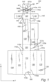
- a blank 100 is shown in Fig. 1 .
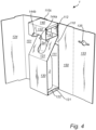
- the blank 100 is configured to be folded into a package 1 as is shown in Figs. 2-4 .
- the blank 100 shown in Fig. 1 is provided with various panels such that it can be folded into a package having a triple layered bottom, a double layered rear wall, a triple layered front wall, and a triple layered top.
- many of the panels may be omitted.
- the blank 100 and package 1 will be discussed with reference to a blank 100 and package 1 comprising all such panels.
- the blank 100 is shown in a flat-laid state.
- the blank 100 comprises a rear wall panel 110, a first bottom panel 120, an inner front wall panel 130, a front straddle panel 131, a rear straddle panel 112, a top panel 140, a top front panel 132, and a top straddle panel 143 being foldably connected and arranged one after the other along a longitudinal direction L.
- the blank 100 may further comprise a second bottom panel 121.
- the second bottom panel 121 is foldably connected to the first bottom panel 120 at a longitudinally extending side 120a thereof.
- the second bottom panel 121 is configured to be folded relative to the first bottom panel 120 such that it extends over an interior surface of the first bottom panel 120 and forms an additional bottom layer of the package 1, as shown in Figs. 2-4 .
- the second bottom panel 121 has approximately the same length and width as the first bottom panel 120.
- the second bottom panel 121 may have a smaller length and/or width than the first bottom panel 120.
- the second bottom panel 121 may have a greater length and/or width than the first bottom panel 120.
- the blank 100 may further comprise a third bottom panel 122 which is foldably connected to a transversally extending side 121a, 121b of the second bottom panel 121 and is configured to be folded relative to the second bottom panel 121 and form an additional bottom layer, as shown in Figs. 2-4 .
- the third bottom panel 122 forms an inner bottom of the package 1, where the bottle 2 is to be placed upon.
- the second bottom panel 121 and the third bottom panel 122 may be folded such that the third bottom panel 122 forms an outer bottom of the package 1, thus, the bottle 2 will be placed upon the first bottom panel 120. This latter works for a design where a rear buffer panel 111 discussed below is omitted or attached to the blank 100 at a different location than to the third bottom panel 122 as disclosed in the drawings.
- the third bottom panel 122 has approximately the same length and width as the first and second bottom panel 120, 121. In another embodiment, the third bottom panel 122 may have a smaller length and/or width than the first and/or second bottom panel 120, 121. Yet alternatively, the third bottom panel 122 may have a greater length and/or width than the first and/or second bottom panel 120, 121.
- the blank 100 may further comprise a rear buffer panel 111.
- the rear buffer panel 111 is foldably connected to the third bottom panel 122 such that the third bottom panel 122 and the rear buffer panel 111 extend one after the other longitudinally and alongside the inner front wall panel 130 as seen in the flat-laid state of the blank 100.
- the rear buffer panel 111 may have an extension in the longitudinal direction which is preferably 60%, more preferably 70%, even more preferably 80% of the longitudinal extension of the rear wall panel 110.
- the blank 100 may comprise a rear buffer panel 111 and an optional third bottom panel 122 each being directly foldably connected to a respective transversally extending side 121a, 121b of the second bottom panel 121 such that the third optional bottom panel 122 extends longitudinally and alongside the inner front wall panel 130 and the rear buffer panel 111 extends longitudinally and alongside the rear wall panel 110 as seen in a flat-laid state of the blank 100.
- the blank 100 may comprise more than three bottom panels.
- a fourth bottom panel may be foldably connected to, e.g., a longitudinally extending side of the first bottom panel 120 being opposite the longitudinally extending side which the second bottom panel 121 is foldably connected to.
- the blank 100 may further comprise a first side wall panel 150, a second side wall panel 151, a first front wall panel 133, and preferably also a second front wall panel 134, wherein the first side wall panel 150 is foldably connected to a first longitudinally extending side 110a of the rear wall panel 110 and the second side wall panel 151 is foldably connected to a second longitudinally extending side 110b of the rear wall panel 110.
- the first front wall panel 133 is preferably foldably connected to the first side wall panel 150 at a longitudinally extending side being opposite the longitudinally extending side which is foldably connected to the rear wall panel 110.
- the second front wall panel 134 is foldably connected to the second side wall panel 151 at a longitudinally extending side being opposite the longitudinally extending side which is foldably connected to the rear wall panel 110.
- the second front wall panel 134 may be arranged on the outside of the first front wall panel 133 when the blank 100 is to be folded into a package 1 and is configured to form an additional front wall layer.
- the first side wall panel 150, the second side wall panel 151, the first front wall panel 133, and the rear wall panel 110 have in the preferred embodiment the same longitudinal length extension.
- the longitudinal length extension of the different wall panels may differ.
- the blank 100 is provided with a first internal recess 160 forming a longitudinally elongated through-going opening in the front straddle panel 131 and in the rear straddle panel 112.
- the first internal recess 160 allows the front straddle panel 131 to be folded such that it bridges a distance between the inner front wall panel 130 and the rear wall panel 110 and where the neck 2a of the bottle 2 is allowed to extend into the opening of the first internal recess 160, as shown in Figs. 2-4 .
- the first internal recess 160 have a drop-shape, however, the shape of the first internal recess 160 may, in another embodiment, have another shape, e.g., rectangular, rectangular with rounded ends, etc.
- the blank 100 is provided with a second internal recess 161 forming a through-going opening in the top straddle panel 143 and preferably also in the top front panel 132.
- the second internal recess 161 has a first and a second portion 161a, 161b, the first portion 161a forming a part of the top straddle panel 143 and the second portion 161b forming a part of the top front panel 132.
- the first portion 161a has preferably a transversally extending width W1 being smaller than a transversally extending width W2 of the second portion 161b of the second internal recess 161.
- the first portion 161a has the same width W1 along its entire extension. However, in another embodiment, the width may vary.
- the second portion 161b has in the preferred embodiment different widths along its extension, but in another embodiment, the width W2 may be the same along the entire extension of the second portion 161b.
- the top straddle panel 143 preferably comprises one or more locking tabs 144, preferably at least two, and most preferably exactly two locking tabs 144a, 144b extending longitudinally from a transversally extending side 143a of the top straddle panel 143.
- the locking tabs 144a, 144b preferably forms a portion within the second portion 161b of the second internal recess 161 when seen in a flat-laid state of the blank 100.
- the top front panel 132 and the top straddle panel 143 are connected by an intermittent fold line 170, the fold line 170 being limited by the two locking tabs 144a, 144b and the second internal recess 161.
- the two locking tabs 144a, 144b are configured to be inserted into a locking recess 135 present in the first front wall panel 133. As seen in Fig. 4 , the locking recess 135 and the locking tabs 144a, 144b of the top straddle panel 143 will be levelled with each other when the blank 100 is folded into the package 1.
- the blank 100 may further comprise a second and a third top panel 141, 142 configured to be folded relative to the top panel 140 and to form additional top layers, as shown in Figs. 2-4 .
- the second and third top panel 141, 142 are foldably connected to a respective longitudinally extending side 140a, 140b of the top panel 140.
- the second top panel 141 is configured to be sandwiched between the top panel 140 and second top panel 142, as shown in Figs. 2-4 .
- the second top panel 141 may comprise a locking tab 145 configured to be inserted into a locking recess 146 of the third top panel 142 when the blank 100 is folded into a package 1.
- the locking tab 145 allows the second and third top panels 141, 142 to be connected to each other and hold their intended top forming position.
- the height of the locking recess 146 of the third top panel 142 may be equal to, or marginally greater than the height of the locking tab 145, i.e., the thickness of the blank 100.
- the second bottom panel 121 has been folded relative to the first bottom panel 120 such that the second bottom panel 121 lies on top of the first bottom panel 120.
- the third bottom panel 122 has then been folded relative to the second bottom panel 121 such that the second bottom panel 121 is sandwiched between the first and second bottom panels 120, 122.
- the rear buffer panel 111 is laid flat over the rear wall panel 110 and forms an inner rear wall of the package 1 and the rear wall panel 110 forms an outer rear wall.
- a bottle 2 is placed upon the third bottom panel 122, wherein the third bottom panel 122 forms an inner bottom of the package 1 and the first bottom panel 120 forms an outer bottom of the package 1.
- the second top panel 141 is sandwiched between the top panel 140 and the third top panel 142, such that the third top panel 142 forms an inner top panel and the top panel 140 forms an outer top panel.
- the rear buffer panel 111 and the rear wall panel 110 are together folded upwardly relative to the bottom panels to form, at least partially, a double layered rear wall.
- the inner front wall panel 130 have been folded upwardly relative to the bottom panels, and the front straddle panel 131 and the rear straddle panel 112 have been folded rearwardly relative to the inner front wall panel 130 such that the front straddle panel 131 straddles a neck 2a of a bottle 2 positioned on the third bottom panel 122.
- This provides structure to the package 1 and the bottle 2 is hindered to move within the package 1, or insert, in a transverse direction T.
- the rear wall panel 110 has been folded upwardly such that it abuts the rear straddle pane 112.
- the top panel 140, and the additional second and third top panels 141, 142, have together been folded forwardly relative to the rear straddle panel 112.
- the third top panel 142 may abut the top of the bottle 2 or there may be a gap between the third top panel 142 and the top of the bottle 2.
- the top front panel 132 have been folded downwardly relative to the top panel 140, and the top straddle panel 143 have been folded rearwardly relative to the top front panel 132 such that the neck 2a of the bottle 2 extends into the opening in the top straddle panel 143.
- the two locking tabs 144a, 144b are, as shown in Fig. 4 , planar with the top straddle panel 143.
- the locking recess 135 of the first front wall panel 133 is configured to receive the at least one locking tab 144a, 144b of the top straddle panel 143 when the blank 100 is folded into a package 1.
- the height of the locking recess 135 of the first front wall panel 133 may be equal to, or marginally greater than the height of the locking tabs 144a, 144b, i.e., the thickness of the blank 100.
- the first and second side wall panels 150, 151 are to be folded upwardly relative to the rear wall panel 110 such that they extend perpendicularly to the rear wall panel 110, not shown in any of the figures.
- the first and second side wall panels 150, 151 are connected to the rear wall panel 110 such that they will be folded into an upright position when the rear wall panel 110 is folded upwardly relative to the first bottom panel 120.
- the first front wall panel 133 is to be folded forwardly such that it becomes parallel with the rear wall panel 110 and the locking tabs 144a, 144b of the top straddle panel 143 are to be inserted into the locking recess 135 of the first front wall panel 133.
- the second front wall panel 134 is to be folded forwardly such that it becomes parallel with the rear wall panel 110 and becomes arranged on the outside of the first front wall panel 133.
- the second front wall panel 134 may be attached to or held against the first front wall panel 133, by attachment means such as, e.g., glue, tape, or interconnecting tabs, between on one hand the second front wall panel 134 and on the other hand the first front wall panel 133, the first side wall panel 151, the outermost bottom panel, and/or the outermost top panel, to close the package 1 and form a continuous loop of walls.
- the package 1 When the package 1 is closed, it may be opened by tearing the attachment means keeping the second front wall 134 against the first front wall panel 133.
- the package 1 may be opened by an integrated tear-off piece 180 included in any of the walls forming a continuous loop of walls, preferably the rear wall panel 110.
- the tear-off piece 180 may be directly torn off by hand, or by tearing off a sticky tape strip placed over the tear-off piece 180 where the tear-off piece 180 is intended to stick to the sticky tape strip when it is removed. It is to be understood that the opening by a tear-off piece 180 is applicable in conjunction with other closing arrangement than the ones described above.
- the top panel 140 is flush with an upper end 110c of the rear wall panel 110.
- the upper end 110c is positioned on the opposite side of the rear wall panel 110 relative to a lower end 110d configured to be foldably connected to the first bottom panel 120, as shown in Fig. 1 .
- the package 1 is provided with a planar top.
- a planar top is e.g., beneficial if several packages 1 are to be stacked on top of each other.
- the top panel 140 may be, and preferably is, flush with a respective upper end of the first and second side wall panels 150, 151 and the first and second front wall panels 133, 134.
- the first bottom panel 120 is flush with the lower end 110d of the rear wall panel 110 being foldably connected to the first bottom panel 120. It is to be understood that when the package 1 is formed into its fully folded stage, the bottom panel 120 may be, and preferably is, flush with a respective lower end of the first and second side wall panels 150, 151 and the first and second front wall panels 133, 134.
- the package is provided with a planar bottom.
- a planar bottom is e.g., beneficial if several packages are to be stacked on top of each other or when the package is to be placed on, e.g., a shelf in a store or warehouse.
Landscapes
- Engineering & Computer Science (AREA)
- Mechanical Engineering (AREA)
- Packages (AREA)
- Cartons (AREA)
- Making Paper Articles (AREA)
Abstract
Description
- The invention relates to a blank configured to be folded into a package or into an insert to be positioned in a package.
- The invention also relates to a method of folding a blank into a package or into an insert.
- When designing a package from a blank, it is often desirous to consider a number of different design criteria. The package should e.g., be designed such that it makes efficient use of material, is easy to prepare for use, is space efficient during transport and storage, and provides a strong structure during use.
- Additionally, for a package which is intended to be used to protect fragile goods it is typically desirous that it is designed such that it can shield or protect the goods packed within the package from external shocks.
- Moreover, it is often desirable that the package is easy to form. This is especially important when the blank is to be folded manually since it is typically desirous that it only requires one person to perform the task. Thus, it is often desirable that the package should be formed in a manner that requires a limited number of folding operations, and/or folding operations which are easy to perform.
- When designing a package, which is intended to be disposed of after use, it is preferred to use a base material with low environmental impact, such as paperboard, use a minimum of such material, and to minimize the need for adhesives or staples, or the like, or at least provide it in a manner making it easy to separate from the base material.
- It is an object of the invention to provide a blank and/or a package addressing at least some of the design criteria that the blank and/or package should provide a strong structure during use, shield the product packed within the package from external shocks, and be easy to recycle.
- This object has been achieved by a blank configured to be folded into a package or into an insert to be positioned in a package, the blank comprising:
- a rear wall panel, a first bottom panel, an inner front wall panel, a front straddle panel, a rear straddle panel, a top panel, a top front panel, and a top straddle panel being foldably connected and arranged one after the other along a longitudinal direction, characterised
- in that the blank is provided with a first internal recess forming a longitudinally elongated through-going opening in the front straddle panel and in the rear straddle panel,
- in that the blank is provided with a second internal recess forming a through-going opening in the top straddle panel,
- in that the front straddle panel and the rear straddle panel are configured to be folded rearwardly relative to the inner front wall panel such that the front straddle panel straddles a neck of a bottle positioned on the bottom panel when the blank is folded into a package or an insert to be positioned in a package, and
- in that the top panel is configured to be folded forwardly relative to the rear straddle panel, the top front panel is configured to be folded downwardly relative to the top panel, and the top straddle panel is configured to be folded rearwardly relative to the top front panel such that the neck of the bottle extends into the opening in the top straddle panel when the blank is folded into a package or an insert to be positioned in a package.
- The blank may be folded into a package, or into an insert intended to be placed within a separate package. The package or insert formed by the blank may be used for transporting and/or storing a bottle, e.g., a wine bottle.
- The front straddle panel is foldably connected to, and intermediately located between, the inner front wall panel and the rear straddle panel. When the blank is folded into a package or an insert, the front straddle panel is configured to bridge a distance between the inner front wall panel and the rear wall panel. The first internal recess of the front straddle panel and the rear straddle panel is configured such that a neck of a bottle, placed upon the bottom panel, is allowed to extend into the opening of the first internal recess. An advantage of having the front straddle panel straddling the neck of the bottle is that the bottle is hindered to move within the package or insert in a transverse direction. It may be noted that internal refers to the recess being located at an inner portion of the blank and preferably also being fully surrounded by uninterrupted material. It may be noted that internal does not necessarily mean that the recess is at an inner portion or fully surrounded by uninterrupted material of the panel it is said to be located in. In the preferred embodiment, a lower end of the first internal recess is located at a distance from a fold line between the inner front wall panel and the front straddle panel. That is, this end of the recess may be said to be internal both with respect to the blank and with respect to the front straddle panel. Furthermore, in the preferred embodiment, the upper end of the first internal recess is located in flush with a fold line between the rear straddle panel and the top panel. That is, this end of the recess may be said to be internal with respect to the blank. Alternatively, the upper end of the recess may be withdrawn downwardly from the fold line between the rear straddle panel and the top panel and in such a case also this end of the recess may be said to be internal both with respect to the blank and with respect to the rear straddle panel.
- An advantage of having the front straddle panel extending from the front of the package, where it is foldably connected to the inner front wall panel, to the rear part of the package, where the rear straddle panel abuts the rear wall panel, is that it provides structural integrity to the package when folded. The front straddle panel prevents the inner front wall panel and the rear wall panel from being displaced towards the packed bottle and it maintains a gap between the bottle and the adjacent walls.
- Since a bottle most often is narrower at an upper part around the neck, compared to the lower parts of the bottle, it is advantageous to have a package designed such that the void within the package, around the neck of the bottle, is partly filled with panels extending transversally to the inner front wall panel and the rear wall panel and that abuts said walls of the package. Such a design will provide the package with a rigid structure.
- The rear straddle panel together with the top panel, the top front panel, and the top straddle panel provides a stronger structure to the upper part of the package. This is advantageous since it provides a package which is less prone to be compromised if the upper part of the package is exposed to external shocks.
- The blank may be made out of paper, such as paperboard or cardboard, or the blank may be made out of another material that has a low environmental impact. The blank is preferably made of a paper-based material, e.g., a material based on paper or paperboard. Paper-based material may provide a lightweight package. Paper-based material may be produced in an environmentally friendly manner and may be recycled in a simple manner. Paper-based material may provide a blank that is easy to transport and handle before the blank is formed to the package. It may be noted that the blank may be made of other materials. It may be noted that the blank as a whole may be made of paper-based material. It may be noted that the blank need not to be made of the same material through-out. The blank may be made of a paper-based material coated or laminated with a polymer-based coating, such as a thermoplastic material, on one or both sides thereof. Such coating may be heat-sealable and/or provide a desired tightness, i.e., barrier properties, such as being waterproof, water resistant, grease proof, grease resistant, food safe, etc.
- The blank may further comprise a second bottom panel and a rear buffer panel,
- wherein the second bottom panel is foldably connected to a longitudinally extending side of the first bottom panel and is configured to be folded relative to the first bottom panel and form an additional bottom layer, and
- wherein the rear buffer panel is directly or indirectly foldably connected to a transversally extending side of the second bottom panel and is configured to be folded relative to the second bottom panel and form an additional rear wall layer.
- The second bottom panel may be folded relative to the first bottom panel such that it extends over an interior surface of the first bottom panel. Put in other words, in an embodiment where the blank comprises two bottom panels forming a double layered bottom of the package, the bottle will preferably be placed upon the second bottom panel. However, the second bottom panel may be folded such that it forms an outer bottom of the package, thus, the bottle will be placed upon the first bottom panel.
- An advantage of having two bottom panels placed on top of each other, creating a double layered bottom of the package, is that the package may provide a better protection to the packed bottle, and it creates a more rigid bottom of the package.
- The second bottom panel may have approximately the same length and width as the first bottom panel, or the second bottom panel may have a smaller length and/or width than the first bottom panel.
- The rear buffer panel may, in an alternative embodiment when being directly foldably connected to the second bottom panel, be connected to the transversally extending side of the second bottom panel such that it extends longitudinally alongside the rear wall panel as seen in a flat-laid state of the blank. When the package is formed, the second bottom panel is, as described above, folded relative to the first bottom panel and the rear buffer panel is laid flat over the rear wall panel. The rear buffer panel and the rear wall panel may together be folded upwardly relative to the bottom panels and forms, at least partially, a double layered rear wall. The rear buffer panel may have an extension in the longitudinal direction which is preferably 60%, more preferably 70%, even more preferably 80% of the longitudinal extension of the rear wall panel.
- An advantage of having a rear buffer panel forming an additional rear wall is that the package is reinforced on the backside which allows for a better protection of the bottle, and it provides the package with a stronger structure and better stability.
- The rear buffer panel may when being indirectly foldably connected to the second bottom panel be indirectly or directly, preferably directly, foldably connected to a third bottom panel. It may in this context be noted that directly foldably connected may be via a single or via a double fold line taking into account that the material may have a material thickness sometimes requiring double fold lines or taking into account that in some cases an additional panel is to be sandwiched between two panels that are said to be directly foldably connected to each other. The third bottom panel may be foldably connected to a transversally extending side of the second bottom panel and is configured to be folded relative to the second bottom panel and form an additional bottom layer. The rear buffer panel may be foldably connected to the third bottom panel such that the third bottom panel and the rear buffer panel extend one after the other longitudinally and alongside the inner front wall panel as seen in a flat-laid state of the blank. When the package is to be formed, the second bottom panel is folded relative to the first bottom panel such that the second bottom panel at least moves towards and typically even lies on top of the first bottom panel and such that the third bottom panel and the rear buffer panel at least moves towards and typically even lies on top of the inner front wall panel and the front straddle panel. The third bottom panel is then to be folded relative to the second bottom panel, such that the second bottom panel is sandwiched between the first and third bottom panels and such that the rear buffer panel is moved towards and typically is laid flat over the rear wall panel. The rear buffer panel and the rear wall panel may together be folded upwardly relative to the bottom panels and form, at least partially, a double layered rear wall.
- An advantage of having three bottom panels placed on top of each other, creating a triple layered bottom of the package, is that the package may provide a better protection to the packed bottle, and it creates a more rigid bottom of the package.
- In another embodiment, the blank may comprise a third bottom panel and a rear buffer panel each being directly foldably connected to a respective transversally extending side of the second bottom panel such that the third bottom panel extend longitudinally alongside the inner front wall panel and the rear buffer panel extend longitudinally alongside the rear wall panel as seen in a flat-laid state of the blank.
- It is to be noted that the blank may comprise more than three bottom panels. A fourth bottom panel may be foldably connected to, e.g., a longitudinally extending side of the first bottom panel being opposite the longitudinally extending side which the second bottom panel may be foldably connected to.
- Preferably, at least when the blank is intended to form a package, the blank may further comprise a first side wall panel, a second side wall panel, and a first front wall panel, wherein preferably the first side wall panel is foldably connected to a first longitudinally extending side of the rear wall panel and the second side wall panel is foldably connected to a second longitudinally extending side of the rear wall panel.
- It is to be noted that the first front wall panel may be foldably connected to a respective second longitudinally extending side of the first side wall panel or the second side wall panel. The respective second longitudinally extending side of the first or second side wall panel is the longitudinally extending side opposite the longitudinally extending side foldably connected to the rear wall panel. When the blank is to be formed into a package, the first and second side wall panels are to be folded upwardly relative to the rear wall panel such that they extend perpendicularly to the rear wall panel and the first front wall panel is to be folded forwardly such that it is parallel with the rear wall panel. The first front wall panel may be attached to the side wall panel, which it is not already foldably connected to, by e.g., glue, tape, or interconnecting tabs, to close the package and form a continuous loop of walls.
- In another embodiment, the first side wall panel may be foldably connected to a first or second longitudinally extending side of the rear wall panel and the first front wall panel may be foldably connected to a longitudinally extending side of the first side wall panel being opposite the longitudinally extending side foldably connected to the rear wall panel. Further, the second side wall panel may be foldably connected to the first front wall panel such that the rear wall panel, the first side wall panel, the first front wall panel, and the second side wall panel extend one after the other in the transverse direction. When the blank is to be folded into a package, the first side wall panel is to be folded upwardly relative to the rear wall panel such that it extends perpendicularly to the rear wall panel and the first front wall panel is to be folded forwardly such that it is parallel with the rear wall panel, and the second side wall panel is to be folded downwardly relative to the first front wall panel. The second side wall panel may be attached to the rear wall panel, by attachment means such as e.g., glue, tape, or interconnecting tabs, to close the package and form a continuous loop of walls.
- When the package is closed, it may be opened by tearing the attachment means between the first front wall panel and the second side wall panel, or the second side wall panel and the rear wall panel. The package may be opened by an integrated tear-off piece included in, e.g., the rear wall panel. The tear-off piece may be directly torn off by hand, or by tearing off a sticky tape strip placed over the tear-off piece where the tear-off piece is intended to stick to the sticky tape strip when its removed. It is to be understood that the opening by a tear-off piece is applicable in conjunction with other closing arrangements than the ones described above.
- Preferably, the first side wall panel, the second side wall panel, the first front wall panel, and the rear wall panel may have the same longitudinal length extension. However, the longitudinal length extension of the different wall panels may differ.
- The first side wall panel, the second side wall panel, the first front wall panel, and the rear wall panel may have the same transversal width extension, or it may be different.
- The blank may further comprise a second front wall panel, wherein preferably the first front wall panel is foldably connected to the first side wall panel and the second front wall panel is foldably connected to the second side wall panel. The second front wall panel may be arranged on the outside of the first front wall panel when the blank is to be folded into a package and is configured to form an additional front wall layer.
- An advantage of having a second front wall panel forming an additional front wall is that the package is reinforced on the front side which allows for a better protection of the bottle, and it provides the package with a stronger structure and better stability.
- The second front wall panel may be attached to the first front wall panel or the first side wall panel by attachment means such as e.g., glue, tape, or interconnecting tabs, to close the package and form a continuous loop of walls.
- Preferably, the second internal recess forms a through-going opening in the top straddle panel and the top front panel. The second internal recess may have a first and a second portion, the first portion being formed in the top straddle panel and the second portion being formed in the top front panel, wherein preferably the first portion of the second internal recess has a transversally extending width being smaller than a transversally extending width of the second portion. The first portion may have the same width along its entire extension, or the width may vary. The second portion may have the same width along its entire extension, or the width may vary.
- The top straddle panel may have at least one locking tab extending longitudinally from a transversally extending side of the top straddle panel, past a fold line between the top straddle panel and the top front panel, and into the top front panel as seen in a flat-laid state of the blank. The fold line between the top front panel and the top straddle panel may be an intermittent fold line, the intermittent fold line being interrupted by said at least one locking tab and the second internal recess. The at least one locking tab may be configured to be planar with the top straddle panel when the blank is folded into a package.
- This way there is provided one or more locking tabs that may interact with an opposing panel, an outer sleeve, or the like. Thereby, the box-shaped structure formed by the top panel, the top front panel and the top straddle panel may be kept in the intended position and thereby in turn keeping the bottle in the intended position.
- It is to be understood that by the intermittent fold line being interrupted by said at least one locking tab and the second internal recess refers to a number of different set-ups depending upon the number and positioning of the locking tabs. There may e.g., be one locking tab on each side of the second internal recess. The locking tab or tabs may be at a distance from the second internal recess, such as at outer longitudinally extending edges of the top front panel and top straddle panel or somewhere between said longitudinally extending edges and the second internal recess. However, in the preferred embodiment, the fold line is provided at both outer longitudinally extending edges and is interrupted in a single interruption, preferably a centrally positioned interruption, centrally as seen in the transverse direction, the single interruption being formed by a first locking tab, directly followed by the second internal recess, and further directly followed by a second locking tab. However, alternatively, the blank may be designed with one or more locking tabs provided at a respective distance from the second recess and in such a case there will be a portion of the fold line present between such a locking tab and the second recess.
- Said at least one locking tab may be formed inside the second portion of the second internal recess when seen in a flat-laid state of the blank. Thereby it is possible to provide a significant portion of uninterrupted fold line on each side of a centrally positioned second internal recess, centrally as seen in a transverse direction, and while still also providing a significant portion of interruption forming said locking tabs. Thus, this positioning of the locking tab or tabs makes efficient use of the available transversal width when it comes to providing the foldable connection, the locking tab or tabs, and the second internal recess. In the preferred embodiment, there are two locking tabs, one at each side of the second internal recess.
- The first front wall panel may comprise at least one locking recess configured to receive the at least one locking tab of the top straddle panel when the blank is folded into a package.
- It may be noted that the number of locking tabs and locking recesses may correspond to each other in a one to one relationship or alternatively such that more than one locking tab is received in a single recess.
- At those portions of the respective recess where the locking tab is inserted, the height of the locking recess of the first front wall panel may be substantially equal to, or marginally greater than the height of the locking tab, i.e., the thickness of the blank. Substantially equal to may also include a height being just slightly smaller than the thickness of the blank such that there is needed a slight force to introduce the respective locking tab in the respective locking recess. This is applicable to also other sets of locking tabs and locking recesses at other parts of the blank. In the preferred embodiment, there are two locking tabs received in a single recess in the front wall panel. In the preferred embodiment, a central portion of the single recess has a height being greater than the thickness of the blank. This central portion may e.g., be used as grip opening allowing the user to insert a finger into the recess to facilitate manoeuvring of the top front panel when folding or unfolding the blank.
- An advantage of having the locking recess of the first front wall panel configured to receive the at least one locking tab of the top straddle panel is that it facilitates keeping the first front wall panel in place relative to the top front panel when the package is formed. It is e.g., possible to design the respective locking recess and the respective locking tab such that there is a friction force between the locking recess and the locking tab such that the first front wall panel stays in place relative to the top front panel when the package is formed.
- The blank may further comprise a second and a third top panel configured to be folded relative to the top panel and to form additional top layers, and wherein preferably the second and third top panel are foldably connected to a respective longitudinally extending side of the top panel.
- The additional top panels provide the package with a thicker and stronger top. The second and third top panels may be folded such that the second top panel is sandwiched between the top panel and third top panel, or vice versa. Preferably the second and third top panels are configured to be folded into an interior of the box-shaped structure formed of the top panel, the top front panel, and the top straddle panel such that the upper most of the second and third top panels is positioned close to and preferably in contact with the top panel and is positioned at a distance from the top straddle panel.
- The second top panel may comprise a locking tab configured to be inserted into a locking recess of the third top panel when the blank is folded into a package, and wherein the second top panel is configured to be sandwiched between the top panel and the third top panel. The locking tab allows the second and third top panels to be connected to each other and hold their intended top forming position. The height of the locking recess of the third top panel may be substantially equal to, or marginally greater than the height of the locking tab, i.e., the thickness of the blank. Although already mentioned to be applicable to also other locking tabs and locking recesses, it may still be mentioned that substantially equal to may also include a height being just slightly smaller than the thickness of the blank such that there is needed a slight force to introduce the respective locking tab in the respective locking recess.
- The top panel may be configured to be flush with an upper end of the rear wall panel when the blank is folded into a package, the upper end being, as seen along the longitudinal direction as seen in a flat-laid state of the blank, on an opposite side of the rear wall panel relative to a lower end foldably connected to the first bottom panel.
- By having the top panel being flush with the upper end of the rear wall panel, the package is provided with a planar top. A planar top is e.g., beneficial if several packages are to be stacked on top of each other. It also facilitates positioning of a sleeve, a bag, an adhesive tape, a gift wrapping, or the like around the thus formed package or insert.
- It is to be understood that in an embodiment where the blank comprises a first and second side wall panel, the top panel may be flush with a respective upper end of the first and second side wall panel. This is also applicable when the blank comprises a first and second front wall panel, i.e., that the top panel may be flush with both the first and second front wall panels.
- The first bottom panel is configured to, when the blank is folded into a package, be flush with the lower end of the rear wall panel being foldably connected to the first bottom panel.
- By having the first bottom panel being flush with the lower end of the rear wall panel, the package is provided with a planar bottom. A planar bottom is e.g., beneficial if several packages are to be stacked on top of each other or when the package is to be placed on, e.g., a shelf in a store or warehouse. It also facilitates positioning of a sleeve, a bag, an adhesive tape, a gift wrapping, or the like around the thus formed package or insert.
- It is to be understood that in an embodiment where the blank comprises a first and second side wall panel the first bottom panel may be flush with a respective lower end of the first and second side wall panel. This is also applicable when the blank comprises a first and second front wall panel, i.e., that the first bottom panel may be flush with both the first and second front wall panels.
- The above object has also been achieved by a method for making a package or an insert from a blank of the kind disclosed above, wherein the method comprises:
- folding the inner front wall panel upwardly relative to the first bottom panel and folding the front straddle panel and the rear straddle panel rearwardly relative to the inner front wall panel such that the front straddle panel straddles a neck of a bottle positioned on the first bottom panel,
- folding the top panel forwardly relative to the rear straddle panel to form a top of the package, folding the top front panel downwardly relative to the top panel, and folding the top straddle panel rearwardly relative to the top front panel such that the neck of the bottle extends into the opening in the top straddle panel,
- folding the rear wall panel upwardly relative to the first bottom panel.
- The method may further comprise folding the second bottom panel towards the first bottom panel to form an additional bottom layer, and folding the rear buffer panel and the rear wall panel upwardly relative to said first and second bottom panels to form a double layered rear wall of the package.
- The method may further comprise folding the third bottom panel relative to the second bottom panel to form an additional bottom layer of the package.
- The method may further comprise folding the second and third top panel relative to the top panel such that the second top panel is sandwiched between the top panel and the third top panel and optionally, but preferably, inserting the optional, but preferred, locking tab of the second top panel into the optional, but preferred, locking recess of the third top panel.
- The method may further comprise folding the first side wall panel, the second side wall panel and the first front wall panel relative to the rear wall panel to form a continuous loop of walls of the package.
- The advantages of the various features have been discussed above with reference to the blank and those advantages are equally applicable with reference to the methods. Also, the various variants discussed with reference to the blank are equally applicable to the methods.
- It may be noted that the use of first, second, third, fourth, fifth, etc. are mainly to be seen as labels facilitating reading and that it does not necessarily mean that there need to be all the intervening numbers of portions present. It may e.g., be noted that it is contemplated to have a design where there is a first portion, a second portion, a third portion and a fifth portion, with the fourth portion being omitted. However, to facilitate reading, we have consistently used the numbering first, second, third, fourth, etc., as labels, and in a sense based on an embodiment including all conceivable portions.
- It may also be noted that panel names such as top, bottom and wall are intended to be read as labels, not necessarily defining the orientation of the panel. As an example, the package does not need to be oriented such that the top panel actually forms the top of the package. The package may be oriented such that the panel labelled top panel actually forms a side wall or even forms a bottom of the package. It does not have to be located over the bottom panel, but could be positioned under, on the side of, or in any other way relative to it. However, in the preferred embodiment, the package will be oriented so that the bottom panel faces downward, the top panels faces upward, and the wall panels faces outwards from an axis between top and bottom.
- Generally, all terms used in the claims are to be interpreted according to their ordinary meaning in the technical field, unless explicitly defined otherwise herein. All references to "a/an/the [element, device, component, means, step, etc]" are to be interpreted openly as referring to at least one instance of said element, device, component, means, step, etc., unless explicitly stated otherwise. The steps of any method disclosed herein do not have to be performed in the exact order disclosed, unless explicitly stated.
- The invention may also in short be said to relate to a rear wall panel, a first bottom panel, an inner front wall panel, a front straddle panel, a rear straddle panel, a top panel, a top front panel, and a top straddle panel being foldably connected and arranged one after the other along a longitudinal direction, wherein the blank is provided with a first internal recess forming a longitudinally elongated through-going opening in the front straddle panel and in the rear straddle panel, and wherein the blank is provided with a second internal recess forming a through-going opening in the top straddle panel.
- The invention will by way of example be described in more detail with reference to the appended schematic drawings, which shows a presently preferred embodiment of the invention.
-
Figure 1 discloses a blank configured to form a package. -
Figure 2 discloses the blank shown infigure 1 , wherein a bottle is placed upon a triple layered bottom. -
Figure 3 discloses how an inner front wall panel and a front straddle panel of the blank, shown infigures 1 and2 , are to be folded in relation to the bottle. -
Figure 4 discloses how a top panel, a top front panel, and a top straddle panel of the blank, shown infigures 1-3 , are to be folded in relation to the bottle. - A blank 100 is shown in
Fig. 1 . The blank 100 is configured to be folded into apackage 1 as is shown inFigs. 2-4 . The blank 100 shown inFig. 1 is provided with various panels such that it can be folded into a package having a triple layered bottom, a double layered rear wall, a triple layered front wall, and a triple layered top. However, as has been discussed above, many of the panels may be omitted. However, in the following, the blank 100 andpackage 1 will be discussed with reference to a blank 100 andpackage 1 comprising all such panels. - With reference to
Fig. 1 , the blank 100 is shown in a flat-laid state. The blank 100 comprises arear wall panel 110, a firstbottom panel 120, an innerfront wall panel 130, afront straddle panel 131, arear straddle panel 112, atop panel 140, a topfront panel 132, and atop straddle panel 143 being foldably connected and arranged one after the other along a longitudinal direction L. The blank 100 may further comprise a secondbottom panel 121. The secondbottom panel 121 is foldably connected to the firstbottom panel 120 at alongitudinally extending side 120a thereof. The secondbottom panel 121 is configured to be folded relative to the firstbottom panel 120 such that it extends over an interior surface of the firstbottom panel 120 and forms an additional bottom layer of thepackage 1, as shown inFigs. 2-4 . The secondbottom panel 121 has approximately the same length and width as the firstbottom panel 120. In another embodiment the secondbottom panel 121 may have a smaller length and/or width than the firstbottom panel 120. Yet alternatively, the secondbottom panel 121 may have a greater length and/or width than the firstbottom panel 120. - The blank 100 may further comprise a third
bottom panel 122 which is foldably connected to atransversally extending side bottom panel 121 and is configured to be folded relative to the secondbottom panel 121 and form an additional bottom layer, as shown inFigs. 2-4 . The thirdbottom panel 122 forms an inner bottom of thepackage 1, where thebottle 2 is to be placed upon. However, in another embodiment, not shown in any of the figures, the secondbottom panel 121 and the thirdbottom panel 122 may be folded such that the thirdbottom panel 122 forms an outer bottom of thepackage 1, thus, thebottle 2 will be placed upon the firstbottom panel 120. This latter works for a design where arear buffer panel 111 discussed below is omitted or attached to the blank 100 at a different location than to the thirdbottom panel 122 as disclosed in the drawings. - The third
bottom panel 122 has approximately the same length and width as the first and secondbottom panel bottom panel 122 may have a smaller length and/or width than the first and/or secondbottom panel bottom panel 122 may have a greater length and/or width than the first and/or secondbottom panel - The blank 100 may further comprise a
rear buffer panel 111. Therear buffer panel 111 is foldably connected to the thirdbottom panel 122 such that the thirdbottom panel 122 and therear buffer panel 111 extend one after the other longitudinally and alongside the innerfront wall panel 130 as seen in the flat-laid state of the blank 100. - The
rear buffer panel 111 may have an extension in the longitudinal direction which is preferably 60%, more preferably 70%, even more preferably 80% of the longitudinal extension of therear wall panel 110. - In another embodiment, the blank 100 may comprise a
rear buffer panel 111 and an optional thirdbottom panel 122 each being directly foldably connected to a respectivetransversally extending side bottom panel 121 such that the thirdoptional bottom panel 122 extends longitudinally and alongside the innerfront wall panel 130 and therear buffer panel 111 extends longitudinally and alongside therear wall panel 110 as seen in a flat-laid state of the blank 100. - It is to be noted that the blank 100 may comprise more than three bottom panels. A fourth bottom panel may be foldably connected to, e.g., a longitudinally extending side of the first
bottom panel 120 being opposite the longitudinally extending side which the secondbottom panel 121 is foldably connected to. - The blank 100 may further comprise a first
side wall panel 150, a secondside wall panel 151, a firstfront wall panel 133, and preferably also a secondfront wall panel 134, wherein the firstside wall panel 150 is foldably connected to a firstlongitudinally extending side 110a of therear wall panel 110 and the secondside wall panel 151 is foldably connected to a secondlongitudinally extending side 110b of therear wall panel 110. The firstfront wall panel 133 is preferably foldably connected to the firstside wall panel 150 at a longitudinally extending side being opposite the longitudinally extending side which is foldably connected to therear wall panel 110. The secondfront wall panel 134 is foldably connected to the secondside wall panel 151 at a longitudinally extending side being opposite the longitudinally extending side which is foldably connected to therear wall panel 110. The secondfront wall panel 134 may be arranged on the outside of the firstfront wall panel 133 when the blank 100 is to be folded into apackage 1 and is configured to form an additional front wall layer. - As seen in
Fig. 1 , the firstside wall panel 150, the secondside wall panel 151, the firstfront wall panel 133, and therear wall panel 110 have in the preferred embodiment the same longitudinal length extension. However, in another embodiment, the longitudinal length extension of the different wall panels may differ. - The blank 100 is provided with a first
internal recess 160 forming a longitudinally elongated through-going opening in thefront straddle panel 131 and in therear straddle panel 112. The firstinternal recess 160 allows thefront straddle panel 131 to be folded such that it bridges a distance between the innerfront wall panel 130 and therear wall panel 110 and where theneck 2a of thebottle 2 is allowed to extend into the opening of the firstinternal recess 160, as shown inFigs. 2-4 . - As seen in
Fig.1 , the firstinternal recess 160 have a drop-shape, however, the shape of the firstinternal recess 160 may, in another embodiment, have another shape, e.g., rectangular, rectangular with rounded ends, etc. - The blank 100 is provided with a second
internal recess 161 forming a through-going opening in thetop straddle panel 143 and preferably also in the topfront panel 132. The secondinternal recess 161 has a first and asecond portion first portion 161a forming a part of thetop straddle panel 143 and thesecond portion 161b forming a part of the topfront panel 132. As shown inFig. 1 , thefirst portion 161a has preferably a transversally extending width W1 being smaller than a transversally extending width W2 of thesecond portion 161b of the secondinternal recess 161. Thefirst portion 161a has the same width W1 along its entire extension. However, in another embodiment, the width may vary. - The
second portion 161b has in the preferred embodiment different widths along its extension, but in another embodiment, the width W2 may be the same along the entire extension of thesecond portion 161b. - As shown in
Fig.1 , thetop straddle panel 143 preferably comprises one or more locking tabs 144, preferably at least two, and most preferably exactly two lockingtabs side 143a of thetop straddle panel 143. The lockingtabs second portion 161b of the secondinternal recess 161 when seen in a flat-laid state of the blank 100. The topfront panel 132 and thetop straddle panel 143 are connected by anintermittent fold line 170, thefold line 170 being limited by the twolocking tabs internal recess 161. The twolocking tabs locking recess 135 present in the firstfront wall panel 133. As seen inFig. 4 , thelocking recess 135 and thelocking tabs top straddle panel 143 will be levelled with each other when the blank 100 is folded into thepackage 1. - The blank 100 may further comprise a second and a third
top panel top panel 140 and to form additional top layers, as shown inFigs. 2-4 . As seen inFig.1 , the second and thirdtop panel longitudinally extending side top panel 140. The secondtop panel 141 is configured to be sandwiched between thetop panel 140 and secondtop panel 142, as shown inFigs. 2-4 . - As further shown in
Fig. 1 , the secondtop panel 141 may comprise alocking tab 145 configured to be inserted into alocking recess 146 of the thirdtop panel 142 when the blank 100 is folded into apackage 1. Thelocking tab 145 allows the second and thirdtop panels locking recess 146 of the thirdtop panel 142 may be equal to, or marginally greater than the height of thelocking tab 145, i.e., the thickness of the blank 100. - With reference to
Fig. 2 , the secondbottom panel 121 has been folded relative to the firstbottom panel 120 such that the secondbottom panel 121 lies on top of the firstbottom panel 120. The thirdbottom panel 122 has then been folded relative to the secondbottom panel 121 such that the secondbottom panel 121 is sandwiched between the first and secondbottom panels rear buffer panel 111 is laid flat over therear wall panel 110 and forms an inner rear wall of thepackage 1 and therear wall panel 110 forms an outer rear wall. Abottle 2 is placed upon the thirdbottom panel 122, wherein the thirdbottom panel 122 forms an inner bottom of thepackage 1 and the firstbottom panel 120 forms an outer bottom of thepackage 1. - As described above, the second
top panel 141 is sandwiched between thetop panel 140 and the thirdtop panel 142, such that the thirdtop panel 142 forms an inner top panel and thetop panel 140 forms an outer top panel. - With reference to
Fig. 3 , therear buffer panel 111 and therear wall panel 110 are together folded upwardly relative to the bottom panels to form, at least partially, a double layered rear wall. - The inner
front wall panel 130 have been folded upwardly relative to the bottom panels, and thefront straddle panel 131 and therear straddle panel 112 have been folded rearwardly relative to the innerfront wall panel 130 such that thefront straddle panel 131 straddles aneck 2a of abottle 2 positioned on the thirdbottom panel 122. This provides structure to thepackage 1 and thebottle 2 is hindered to move within thepackage 1, or insert, in a transverse direction T. - With reference to
Fig. 4 , therear wall panel 110 has been folded upwardly such that it abuts therear straddle pane 112. Thetop panel 140, and the additional second and thirdtop panels rear straddle panel 112. The thirdtop panel 142 may abut the top of thebottle 2 or there may be a gap between the thirdtop panel 142 and the top of thebottle 2. Further, as shown inFig. 4 , the topfront panel 132 have been folded downwardly relative to thetop panel 140, and thetop straddle panel 143 have been folded rearwardly relative to the topfront panel 132 such that theneck 2a of thebottle 2 extends into the opening in thetop straddle panel 143. Moreover, the twolocking tabs Fig. 4 , planar with thetop straddle panel 143. Thelocking recess 135 of the firstfront wall panel 133 is configured to receive the at least onelocking tab top straddle panel 143 when the blank 100 is folded into apackage 1. - The height of the
locking recess 135 of the firstfront wall panel 133 may be equal to, or marginally greater than the height of thelocking tabs - When the blank 100 is to be formed into a
package 1, the first and secondside wall panels rear wall panel 110 such that they extend perpendicularly to therear wall panel 110, not shown in any of the figures. In the preferred embodiment, the first and secondside wall panels rear wall panel 110 such that they will be folded into an upright position when therear wall panel 110 is folded upwardly relative to the firstbottom panel 120. Further, the firstfront wall panel 133 is to be folded forwardly such that it becomes parallel with therear wall panel 110 and thelocking tabs top straddle panel 143 are to be inserted into thelocking recess 135 of the firstfront wall panel 133. There may be formed a friction force between the lockingrecess 135 and thelocking tabs locking tabs locking recess 135. Such a friction force aids in keeping the firstfront wall panel 133 in the intended position relative to the topfront panel 132 when thepackage 1 is formed. - The second
front wall panel 134 is to be folded forwardly such that it becomes parallel with therear wall panel 110 and becomes arranged on the outside of the firstfront wall panel 133. The secondfront wall panel 134 may be attached to or held against the firstfront wall panel 133, by attachment means such as, e.g., glue, tape, or interconnecting tabs, between on one hand the secondfront wall panel 134 and on the other hand the firstfront wall panel 133, the firstside wall panel 151, the outermost bottom panel, and/or the outermost top panel, to close thepackage 1 and form a continuous loop of walls. - When the
package 1 is closed, it may be opened by tearing the attachment means keeping the secondfront wall 134 against the firstfront wall panel 133. Alternatively, thepackage 1 may be opened by an integrated tear-off piece 180 included in any of the walls forming a continuous loop of walls, preferably therear wall panel 110. The tear-off piece 180 may be directly torn off by hand, or by tearing off a sticky tape strip placed over the tear-off piece 180 where the tear-off piece 180 is intended to stick to the sticky tape strip when it is removed. It is to be understood that the opening by a tear-off piece 180 is applicable in conjunction with other closing arrangement than the ones described above. - As shown in
Fig. 4 , thetop panel 140 is flush with anupper end 110c of therear wall panel 110. Theupper end 110c is positioned on the opposite side of therear wall panel 110 relative to alower end 110d configured to be foldably connected to the firstbottom panel 120, as shown inFig. 1 . By having thetop panel 140 being flush with theupper end 110c of therear wall panel 110, thepackage 1 is provided with a planar top. A planar top is e.g., beneficial ifseveral packages 1 are to be stacked on top of each other. - It is to be understood that when the
package 1 is formed into its fully folded stage, thetop panel 140 may be, and preferably is, flush with a respective upper end of the first and secondside wall panels front wall panels - As shown in
Fig. 4 , the firstbottom panel 120 is flush with thelower end 110d of therear wall panel 110 being foldably connected to the firstbottom panel 120. It is to be understood that when thepackage 1 is formed into its fully folded stage, thebottom panel 120 may be, and preferably is, flush with a respective lower end of the first and secondside wall panels front wall panels bottom panel 120 being flush with thelower end 110d of therear wall panel 110, the package is provided with a planar bottom. A planar bottom is e.g., beneficial if several packages are to be stacked on top of each other or when the package is to be placed on, e.g., a shelf in a store or warehouse. - Even though it is preferred that the blank 100 is designed in accordance with the disclosure in the detailed disclosure of preferred embodiments and the appended drawings, it should be noted that a specific preferred embodiment of a specific component does not necessarily have to be combined with a specific embodiment of another component.
- Additionally, variations to the disclosed embodiments can be understood and effected by the skilled person in practicing the claimed invention, from a study of the drawings, the disclosure, and the appended claims. In the claims, the word "comprising" does not exclude other elements or steps, and the indefinite article "a" or "an" does not exclude a plurality. The mere fact that certain measures are recited in mutually different dependent claims does not indicate that a combination of these measures cannot be used to advantage.
Claims (16)
- Blank (100) configured to be folded into a package (1) or into an insert to be positioned in a package, the blank (100) comprising:a rear wall panel (110), a first bottom panel (120), an inner front wall panel (130), a front straddle panel (131), a rear straddle panel (112), a top panel (140), a top front panel (132), and a top straddle panel (143) being foldably connected and arranged one after the other along a longitudinal direction (L), characterisedin that the blank (100) is provided with a first internal recess (160) forming a longitudinally elongated through-going opening in the front straddle panel (131) and in the rear straddle panel (112),in that the blank (100) is provided with a second internal recess (161) forming a through-going opening in the top straddle panel (143),in that the front straddle panel (131) and the rear straddle panel (112) are configured to be folded rearwardly relative to the inner front wall panel (130) such that the front straddle panel (131) straddles a neck (2a) of a bottle (2) positioned on the bottom panel (120) when the blank (100) is folded into a package (1) or an insert to be positioned in a package, andin that the top panel (140) is configured to be folded forwardly relative to the rear straddle panel (112), the top front panel (132) is configured to be folded downwardly relative to the top panel (140), and the top straddle panel (143) is configured to be folded rearwardly relative to the top front panel (132) such that the neck (2a) of the bottle (2) extends into the opening in the top straddle panel (143) when the blank (100) is folded into a package (1) or an insert to be positioned in a package.
- Blank (100) according to claim 1, wherein the blank (100) further comprises a second bottom panel (121) and a rear buffer panel (111),wherein the second bottom panel (121) is foldably connected to a longitudinally extending side (120a) of the first bottom panel (120) and is configured to be folded relative to the first bottom panel (120) and form an additional bottom layer when the blank (100) is folded into a package (1) or an insert to be positioned in a package, andwherein the rear buffer panel (111) is directly or indirectly foldably connected to a transversally extending side (121a, 121b) of the second bottom panel (121) and is configured to be folded relative to the second bottom panel (121) and form an additional rear wall layer when the blank (100) is folded into a package (1) or an insert to be positioned in a package.
- Blank (100) according to claim 2, wherein the blank (100) further comprises a third bottom panel (122) which is foldably connected to a transversally extending side (121a, 121b) of the second bottom panel (121) and which is configured to be folded relative to the second bottom panel (121) and form an additional bottom layer when the blank (100) is folded into a package (1) or an insert to be positioned in a package,
wherein the rear buffer panel (111) is foldably connected to the third bottom panel (122) such that the third bottom panel (122) and the rear buffer panel (111) extend one after the other longitudinally and alongside the inner front wall panel (130) as seen in a flat-laid state of the blank (100). - Blank (100) according to any one of the claims 1-3, wherein the blank (100) further comprises a first side wall panel (150), a second side wall panel (151), and a first front wall panel (133),
wherein preferably the first side wall panel (150) is foldably connected to a first longitudinally extending side (110a) of the rear wall panel (110), the second side wall panel (151) is foldably connected to a second longitudinally extending side (110b) of the rear wall panel (110), and the first front wall panel (133) is foldably connected to the first side wall panel (150). - Blank (100) according to claim 4, wherein the blank (100) further comprises a second front wall panel (134),
wherein preferably the second front wall panel (134) is foldably connected to the second side wall panel (151). - Blank (100) according to any one of the claims 1-5, wherein the second internal recess (161) forms a through-going opening in the top straddle panel (143) and the top front panel (132).
- Blank (100) according to claim 6, wherein the second internal recess (161) has a first and a second portion (161a, 161b), the first portion (161a) being formed in the top straddle panel (143) and the second portion (161b) being formed in the top front panel (132),
wherein preferably the first portion (161a) of the second internal recess (161) has a transversally extending width (W1) being smaller than a transversally extending width (W2) of the second portion (161b) of the second internal recess (161). - Blank (100) according to claim 1-7, wherein the top straddle panel (143) has at least one locking tab (144a, 144b) which extends longitudinally from a transversally extending side (143a) of the top straddle panel (143), past a fold line (170) between the top straddle panel (143) and the top front panel (132), and into the top front panel (132) as seen in a flat-laid state of the blank (100),wherein the fold line (170) between the top front panel (132) and the top straddle panel (143) is an intermittent fold line (170), the intermittent fold line (170) being interrupted by said at least one locking tab (144a, 144b) and by the second internal recess (161),wherein the at least one locking tab (144a, 144b) is configured to be planar with the top straddle panel (143) when the blank (100) is folded into a package (1).
- Blank (100) according to claim 8, wherein said at least one locking tab (144a, 144b) is formed inside the second portion (161b) of the second internal recess (161) when seen in a flat-laid state of the blank (100).
- Blank (100) according to claim 8 or 9 when including a dependency of claim 4, wherein the first front wall panel (133) comprises at least one locking recess (135) configured to receive the at least one locking tab (144a, 144b) of the top straddle panel (143) when the blank (100) is folded into a package (1).
- Blank (100) according to any one of the claims 1-10, wherein the blank (100) further comprises a second and a third top panel (141, 142) configured to be folded relative to the top panel (140) and to form additional top layers when the blank (100) is folded into a package (1) or an insert to be positioned in a package, and
wherein preferably the second and third top panel (141, 142) are foldably connected to a respective longitudinally extending side (140a, 140b) of the top panel (140). - Blank (100) according to claim 11, wherein the second top panel (141) comprises a locking tab (145) configured to be inserted into a locking recess (146) of the third top panel (142) when the blank (100) is folded into a package (1), and
wherein the second top panel (141) is configured to be sandwiched between the top panel and the third top panel (140, 142) when the blank (100) is folded into a package (1) or an insert to be positioned in a package. - Blank (100) according to any one of the claims 1-12, wherein the top panel (140) is configured to be flush with an upper end (110c) of the rear wall panel (110) when the blank (100) is folded into a package (1), the upper end (110c) being, as seen along the longitudinal direction as seen in a flat-laid state of the blank (100), on an opposite side of the rear wall panel (110) relative to a lower end (110d) foldably connected to the first bottom panel (120).
- Blank (100) according to any one of the claims 1-12, wherein the first bottom panel (120) is configured to, when the blank (100) is folded into a package (1), be flush with a lower end (110d) of the rear wall panel (110) being foldably connected to the first bottom panel (120).
- Blank (100) according to claim 13, wherein the first bottom panel (120) is configured to, when the blank (100) is folded into a package (1), be flush with the lower end (110d) of the rear wall panel (110) being foldably connected to the first bottom panel (120).
- Method of folding a blank (100) according to any one of the claims 1-15 into a package (1) or into an insert, the method comprising:folding the inner front wall panel (130) upwardly relative to the first bottom panel (120) and folding the front straddle panel (131) and the rear straddle panel (112) rearwardly relative to the inner front wall panel (130) such that the front straddle panel (131) straddles a neck (2a) of a bottle (2) positioned on the first bottom panel (120),folding the top panel (140) forwardly relative to the rear straddle panel (112) to form a top of the package (1), folding the top front panel (132) downwardly relative to the top panel (140), and folding the top straddle panel (143) rearwardly relative to the top front panel (132) such that the neck (2a) of the bottle (2) extends into the opening in the top straddle panel (143),folding the rear wall panel (110) upwardly relative to the first bottom panel (120).
Applications Claiming Priority (1)
| Application Number | Priority Date | Filing Date | Title |
|---|---|---|---|
| SE2330367A SE547731C2 (en) | 2023-08-25 | 2023-08-25 | Blank and method of folding a blank |
Publications (3)
| Publication Number | Publication Date |
|---|---|
| EP4516688A1 true EP4516688A1 (en) | 2025-03-05 |
| EP4516688B1 EP4516688B1 (en) | 2026-04-15 |
| EP4516688C0 EP4516688C0 (en) | 2026-04-15 |
Family
ID=92538848
Family Applications (1)
| Application Number | Title | Priority Date | Filing Date |
|---|---|---|---|
| EP24195933.7A Active EP4516688B1 (en) | 2023-08-25 | 2024-08-22 | Blank and method of folding a blank |
Country Status (3)
| Country | Link |
|---|---|
| EP (1) | EP4516688B1 (en) |
| PL (1) | PL4516688T3 (en) |
| SE (1) | SE547731C2 (en) |
Citations (4)
| Publication number | Priority date | Publication date | Assignee | Title |
|---|---|---|---|---|
| SE336105B (en) * | 1967-11-10 | 1971-06-21 | K Reynold | |
| CN103318561A (en) * | 2013-07-11 | 2013-09-25 | 广东工业大学 | Wine bottle buffering package structure |
| CN114620310A (en) * | 2020-12-11 | 2022-06-14 | 天津市职业大学 | A shock-absorbing red wine gift box and its blank and forming method |
| US20220396391A1 (en) * | 2019-11-13 | 2022-12-15 | 3.7 S.r.l. | Packaging for holding bottles |
Family Cites Families (1)
| Publication number | Priority date | Publication date | Assignee | Title |
|---|---|---|---|---|
| DE202009012304U1 (en) * | 2009-09-11 | 2009-11-19 | Karl Knauer Kg | Bottle carrier and cut to its training |
-
2023
- 2023-08-25 SE SE2330367A patent/SE547731C2/en unknown
-
2024
- 2024-08-22 EP EP24195933.7A patent/EP4516688B1/en active Active
- 2024-08-22 PL PL24195933.7T patent/PL4516688T3/en unknown
Patent Citations (4)
| Publication number | Priority date | Publication date | Assignee | Title |
|---|---|---|---|---|
| SE336105B (en) * | 1967-11-10 | 1971-06-21 | K Reynold | |
| CN103318561A (en) * | 2013-07-11 | 2013-09-25 | 广东工业大学 | Wine bottle buffering package structure |
| US20220396391A1 (en) * | 2019-11-13 | 2022-12-15 | 3.7 S.r.l. | Packaging for holding bottles |
| CN114620310A (en) * | 2020-12-11 | 2022-06-14 | 天津市职业大学 | A shock-absorbing red wine gift box and its blank and forming method |
Also Published As
| Publication number | Publication date |
|---|---|
| SE547731C2 (en) | 2025-11-18 |
| SE2330367A1 (en) | 2025-02-26 |
| EP4516688B1 (en) | 2026-04-15 |
| PL4516688T3 (en) | 2026-06-29 |
| EP4516688C0 (en) | 2026-04-15 |
Similar Documents
| Publication | Publication Date | Title |
|---|---|---|
| JP5307882B2 (en) | Carton with handle | |
| CA2692785C (en) | Carton with dispenser, display features and/or corner features | |
| CN104470823B (en) | Carton with plug-in unit and forming method thereof | |
| CN104220343B (en) | Assembly of carton blank and pallet blank, carton and method of forming carton | |
| CN102482015B (en) | Carton with handle | |
| CN102482013B (en) | Carton with insert, carton blank and reinforced insert combination, and method for forming carton | |
| US10099807B2 (en) | Reversible box with tear-away strips | |
| CN102892685B (en) | Carton with insert | |
| CN104136342B (en) | Carton for carrying multiple articles and blank and method for forming same | |
| US8356744B2 (en) | Carton with reinforcing insert | |
| CN107000859B (en) | carton for items | |
| CN103889852B (en) | Carton, carton blank and the method forming carton | |
| JP2012500754A (en) | Carton with insert | |
| CN104470821A (en) | Carton with article protection insert | |
| CN104114459B (en) | With the carton for strengthening handle | |
| CN101479157A (en) | Cartons with liquid-tight receptacles | |
| MX2010011090A (en) | Gusseted carton. | |
| MX2008009143A (en) | Package for containers. | |
| EP3464088B1 (en) | Package including carton with insert | |
| MX2013003095A (en) | Carton with handle. | |
| BR112014019126B1 (en) | packaging to house a plurality of articles, blanket to form a package, blanket, and method of assembling a package | |
| CN104284843A (en) | Carton with handle | |
| US20110272457A1 (en) | Combination Shipping And Display Package | |
| EP4516688B1 (en) | Blank and method of folding a blank | |
| EP4410698B1 (en) | Kit of blanks, and a package |
Legal Events
| Date | Code | Title | Description |
|---|---|---|---|
| PUAI | Public reference made under article 153(3) epc to a published international application that has entered the european phase |
Free format text: ORIGINAL CODE: 0009012 |
|
| STAA | Information on the status of an ep patent application or granted ep patent |
Free format text: STATUS: THE APPLICATION HAS BEEN PUBLISHED |
|
| AK | Designated contracting states |
Kind code of ref document: A1 Designated state(s): AL AT BE BG CH CY CZ DE DK EE ES FI FR GB GR HR HU IE IS IT LI LT LU LV MC ME MK MT NL NO PL PT RO RS SE SI SK SM TR |
|
| STAA | Information on the status of an ep patent application or granted ep patent |
Free format text: STATUS: REQUEST FOR EXAMINATION WAS MADE |
|
| 17P | Request for examination filed |
Effective date: 20250905 |
|
| GRAP | Despatch of communication of intention to grant a patent |
Free format text: ORIGINAL CODE: EPIDOSNIGR1 |
|
| STAA | Information on the status of an ep patent application or granted ep patent |
Free format text: STATUS: GRANT OF PATENT IS INTENDED |
|
| RIC1 | Information provided on ipc code assigned before grant |
Ipc: B65D 5/02 20060101AFI20251208BHEP Ipc: B65D 5/42 20060101ALI20251208BHEP Ipc: B65D 5/50 20060101ALI20251208BHEP |
|
| INTG | Intention to grant announced |
Effective date: 20251218 |
|
| GRAS | Grant fee paid |
Free format text: ORIGINAL CODE: EPIDOSNIGR3 |
|
| GRAA | (expected) grant |
Free format text: ORIGINAL CODE: 0009210 |
|
| STAA | Information on the status of an ep patent application or granted ep patent |
Free format text: STATUS: THE PATENT HAS BEEN GRANTED |
|
| AK | Designated contracting states |
Kind code of ref document: B1 Designated state(s): AL AT BE BG CH CY CZ DE DK EE ES FI FR GB GR HR HU IE IS IT LI LT LU LV MC ME MK MT NL NO PL PT RO RS SE SI SK SM TR |
|
| REG | Reference to a national code |
Ref country code: CH Ref legal event code: F10 Free format text: ST27 STATUS EVENT CODE: U-0-0-F10-F00 (AS PROVIDED BY THE NATIONAL OFFICE) Effective date: 20260415 |
|
| REG | Reference to a national code |
Ref country code: IE Ref legal event code: FG4D |
|
| U01 | Request for unitary effect filed |
Effective date: 20260417 |
|
| U07 | Unitary effect registered |
Designated state(s): AT BE BG DE DK EE FI FR IT LT LU LV MT NL PT RO SE SI Effective date: 20260424 |