EP4516640A1 - Steuerung eines gelenkfahrzeugs - Google Patents
Steuerung eines gelenkfahrzeugs Download PDFInfo
- Publication number
- EP4516640A1 EP4516640A1 EP23193771.5A EP23193771A EP4516640A1 EP 4516640 A1 EP4516640 A1 EP 4516640A1 EP 23193771 A EP23193771 A EP 23193771A EP 4516640 A1 EP4516640 A1 EP 4516640A1
- Authority
- EP
- European Patent Office
- Prior art keywords
- articulation angle
- articulated vehicle
- steering
- torque
- processing circuitry
- Prior art date
- Legal status (The legal status is an assumption and is not a legal conclusion. Google has not performed a legal analysis and makes no representation as to the accuracy of the status listed.)
- Granted
Links
Images


Classifications
-
- B—PERFORMING OPERATIONS; TRANSPORTING
- B62—LAND VEHICLES FOR TRAVELLING OTHERWISE THAN ON RAILS
- B62D—MOTOR VEHICLES; TRAILERS
- B62D12/00—Steering specially adapted for vehicles operating in tandem or having pivotally connected frames
-
- B—PERFORMING OPERATIONS; TRANSPORTING
- B62—LAND VEHICLES FOR TRAVELLING OTHERWISE THAN ON RAILS
- B62D—MOTOR VEHICLES; TRAILERS
- B62D6/00—Arrangements for automatically controlling steering depending on driving conditions sensed and responded to, e.g. control circuits
- B62D6/002—Arrangements for automatically controlling steering depending on driving conditions sensed and responded to, e.g. control circuits computing target steering angles for front or rear wheels
-
- B—PERFORMING OPERATIONS; TRANSPORTING
- B62—LAND VEHICLES FOR TRAVELLING OTHERWISE THAN ON RAILS
- B62D—MOTOR VEHICLES; TRAILERS
- B62D6/00—Arrangements for automatically controlling steering depending on driving conditions sensed and responded to, e.g. control circuits
- B62D6/008—Control of feed-back to the steering input member, e.g. simulating road feel in steer-by-wire applications
Definitions
- Articulated vehicles with permanent articulation are common in some heavy-duty applications such as off-road vehicles, e.g. articulated haulers, articulated dump trucks etc.
- articulated vehicles feature a permanent pivot joint that allows the front and rear sections of the vehicle to articulate independently around the pivot joint. This unique construction gives them exceptional maneuverability and stability, making them well-suited for navigating rough and uneven surfaces while carrying heavy loads.
- a computer system comprising processing circuitry.
- the processing circuitry is configured to obtain an articulation angle of an articulated vehicle and a velocity of the articulated vehicle, wherein the articulation angle is controlled by a steering input unit, SIU, of a steering system of the articulated vehicle.
- the processing circuitry is further configured to, responsive to the articulation angle deviating from 0°, determine an angular speed for controlling the articulation angle towards 0° based on the articulation angle and a magnitude of the velocity such that a direction of the velocity is maintained and determine a steer-to-center torque for controlling the articulation angle towards 0° based on the angular speed.
- the processing circuitry is further configured to provide the steer-to-center torque to the steering system for control of the articulation angle.
- the first aspect of the disclosure may seek to improve difficulties in manually operating an articulated vehicle.
- a technical benefit may include improved stability as steer-to-center helps to improve the overall stability and control of the articulated vehicle. After completing a turn, the SIU naturally returns to the center position without altering a direction of the vehicle, which can reduce the chances of oversteering or understeering, thereby making the vehicle easier to handle.
- the operation of the articulated vehicle is simplified reducing training required by operators.
- the computer system comprises the steering system.
- a technical benefit may include allowing for more freedom in methods of controlling the articulation angle.
- the processing circuitry is further configured to control a haptic feedback of the SIU based on the steer-to-center torque.
- a technical benefit may include improved stability as steer-to-center helps improve the overall stability and control of the articulated vehicle. After completing a turn, the SIU naturally returns to the center position without altering a direction of the vehicle, which can reduce the chances of oversteering or understeering, making the vehicle easier to handle. The operation of the articulated vehicle is simplified reducing training required by operators.
- the processing circuitry is further configured to control a hydraulic steering actuator of the steering system based on the steer-to-center torque.
- a technical benefit may include allowing the hydraulic steering actuator to return to center as hydraulic steering actuators have no inherent function of returning to zero.
- the processing circuitry is further configured to obtain a wanted articulation angle of the articulated vehicle, from the SIU, and determine a wanted articulation torque for controlling the articulation angle towards the wanted articulation angle.
- a technical benefit may include allowing control also of the articulated vehicle based on operator input.
- the processing circuitry is further configured to control the articulation angle by applying the wanted articulation torque and the steer-to-center torque to a steering actuator of the steering system.
- a technical benefit may include permitting direct control of the articulation angle allowing smooth and controlled steer-to-center functionality.
- the computer system further comprises the steering system, wherein the SIU is a SIU of the articulated vehicle, the steering system is a steer-by-wire, SbW, steering system, wherein the processing circuitry is further configured to: control a haptic feedback of the SIU based on the steer-to-center torque; control a hydraulic steering actuator of the steering system based on the steer-to-center torque; obtain a wanted articulation angle of the articulated vehicle, from the steering input unit, SIU, and determine a wanted articulation torque for controlling the articulation angle towards the wanted articulation angle; and control the articulation angle by applying the wanted articulation torque and the steer-to-center torque to a steering actuator of the steering system.
- a technical benefit may include all the benefits of the previous examples.
- an articulated vehicle comprises a steering system and the computer system according to the first aspect.
- the second aspect of the disclosure may seek to provide a vehicle that reduces some if the difficulties in operating an articulated vehicle.
- a technical benefit may include improved stability as steer-to-center helps improve the overall stability and control of the articulated vehicle. After completing a turn, the SIU naturally returns to the center position without altering a direction of the vehicle, which can reduce the chances of oversteering or understeering, making the vehicle easier to handle.
- the operation of the articulated vehicle is simplified reducing training required by operators.
- the articulated vehicle is a heavy-duty vehicle.
- the steering system is a hydraulic steering system.
- the articulated vehicle is a SbW vehicle.
- a computer implemented method comprises obtaining, by processing circuitry of a computer system, an articulation angle of an articulated vehicle and a velocity of the articulated vehicle, wherein the articulation angle is controlled by a SIU, of a steering system of the articulated vehicle.
- a technical benefit may include improved stability as steer-to-center helps improve the overall stability and control of the articulated vehicle. After completing a turn, the SIU naturally returns to the center position without altering a direction of the vehicle, which can reduce the chances of oversteering or understeering, thereby making the vehicle easier to handle.
- the operation of the articulated vehicle is simplified reducing training required by operators.
- a computer program product comprising program code for performing, when executed by a processing circuitry, the method of the third aspect.
- a non-transitory computer-readable storage medium comprising instructions, which when executed by a processing circuitry, cause the processing circuitry to perform the method of the third aspect.
- the present disclosure will provide functions, features and examples that may simplifies operation of an articulated vehicle.
- steer-to-center (StC) functionality of articulated vehicles may be provided in a way that offers operation of an articulated vehicle that is similar to that of a conventional (rigid) vehicle, i.e. a vehicle with Ackermann steering.
- One effect may be a reduced need of operator training, decreased risk of accidents and improved precision in steering of the articulated vehicle.
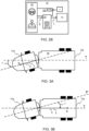
- the pull unit 10a and the trailing unit 10b are pivotably connected at an articulation joint 15.
- the articulation joint 15 allows pull unit 10a and the trailing unit 10b of the vehicle 10 to pivot relative to each other about a vertical axis when the ground surface is perfectly flat/horizontal.
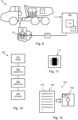
- the articulated vehicle 10 further comprises all vehicle units and associated functionality to operate as expected, such as a powertrain, chassis, and various control systems.
- the vehicle 10 comprises one or more propulsion sources 12.
- the propulsion source 12 may be any suitable propulsion source 12 exemplified by, but not limited to, one or more or a combination of an electrical motor, an internal combustion engine such as a diesel, gas or gasoline powered engine.
- the articulated vehicle 10 further comprises an energy source 14 suitable for providing energy for the propulsion source 12. That is to say, if the propulsion source 12 is an electrical motor, a suitable energy source 14 would be a battery or a fuel cell.
- the articulated vehicle 10 further comprises sensor circuitry 16 arranged to detect, measure, sense or otherwise obtain data relevant for operation of the articulated vehicle 10.
- the sensor circuitry 16 may comprise one or more of an accelerometer, a gyroscope, a wheel Speed Sensor, an ABS sensor, a throttle position sensor, a fuel level sensor, a temperature Sensor, a pressure sensor, a rain sensor, a light sensor, proximity sensor, a lane departure warning sensor, a blind spot detection sensor, a TPMS sensor etc.
- the data relevant for operation of the articulated vehicle 10 may include, but is not limited to, one or more of a speed of the articulated vehicle 10, a weight of the articulated vehicle 10, an inclination of the articulated vehicle 10, a status of the energy source 14 of the articulated vehicle 10 (state of charge, fuel level etc.), a presence of road users in a vicinity of the articulated vehicle 10, a current speed limit of a current road travelled by the articulated vehicle 10, an articulation angle of the articulated vehicle 10 etc.
- the communications interface may be a wireless communications interface exemplified by, but not limited to, Wi-Fi, Bluetooth, Zigbee, Z-Wave, LoRa, Sigfox, 2G (GSM, CDMA), 3G (UMTS, CDMA2000), 4G (LTE), 5G (NR) etc.
- the articulated vehicle 10 may further be operatively connected to a Global Navigation Satellite System (GNSS) 40 exemplified by, but not limited to, global positioning system (GPS), Globalnaya Navigatsionnaya Sputnikovayassela (GLONASS), Galileo, BeiDou Navigation Satellite System, Navigation with Indian Constellation (NavIC) etc.
- the vehicle 10 may be configured to utilize data obtain from the GNSS 40 to determine a geographical location of the vehicle 10.
- the articulated vehicle 10 further comprises a steering system 20 and a computer system 100.
- the computer system 100 comprises processing circuitry 110.
- the steering system 21 comprises processing circuitry 21.
- the processing circuitry 21 of the steering system 20 may be part of the processing circuitry 110 of the computer system 100.
- the computer system 100 may comprise the steering system 20.
- the steering system 20 is configured to control steering of the articulated vehicle 10, i.e. to control an articulation angle ⁇ of the articulation joint 15 based on a wanted (i.e. desired) articulation angle ⁇ .
- the wanted articulation angle ⁇ is provided by a steering input unit (SIU) 25 operatively connected to the steering system 20.
- SIU steering input unit
- the wanted/desired articulation angle ⁇ evolves proportionally with a position of the SIU 25, and more precisely to the deviation of the position of the SIU 25 relative to a neutral/straight position of the SIU 25.
- the wanted/desired articulation angle ⁇ corresponds to a maximum allowable articulation angle.
- the wanted articulation angle ⁇ is equal to half of the maximum allowable articulation angle (according to proportionality law).
- the SIU 25 may be a remotely located SIU 25 for remote control of the articulated vehicle 10. However, as seen in FIG.
- the SIU 25 may also be part of the articulated vehicle 10.
- the SIU 25 may any suitable device such as a steering wheel, a joystick, keyboard etc.
- no mechanical connection is provided between the SIU 25 and the articulation joint 15, this is generally known as a steer by wire (SbW) system. Due to the complexity of steering systems for articulated vehicles 10, the steering is generally provided by a SbW system.
- the steering system 20 may control the articulation angle ⁇ in one or more different ways.
- the articulation angle ⁇ may be controlled by a steering actuator 23 of the steering system 20.
- the steering actuator 23 may be a hydraulic steering actuator comprising a hydraulic system arranged to control movement of the articulation angle ⁇ .
- hydraulic cylinders are connected to the articulation joint 15 and provide required force to articulate the articulated vehicle 10. By controlling the flow of hydraulic fluid to the cylinders, the operator may adjust the articulation angle ⁇ .
- the steering actuator 23 may be a differential steering actuator configured to adjust a relative speed of wheels on a left and right sides of the articulation joint 15.
- the steering actuator 23 may be an electrical steering actuator comprising electric motors arranged to control movement of the articulation angle ⁇ .
- the examples of steering actuators 23 are given as way of example and should not be considered exhaustive.
- FIG. 3A is a top view of an articulated vehicle 10 moving in a (forward) direction d with a speed s.
- the speed s and the direction d are indicated by a velocity v.
- the velocity v is a vector having the direction d and having a magnitude describing the speed s.
- the velocity v need only contain a speed s (a magnitude of the velocity v ) and a direction indicator indicating a forward or a backwards direction of the articulated vehicle 10. That is to say, the direction d does not have to be a direction in a plane.
- FIG. 3A is a top view of an articulated vehicle 10 moving in a (forward) direction d with a speed s.
- the speed s and the direction d are indicated by a velocity v.
- the velocity v is a vector having the direction d and having a magnitude describing the speed s.
- the velocity v need only contain a speed s (a magnitude of the velocity v ) and
- the tractor unit 10a of the articulated vehicle 10 is the forward one (leading unit) of the tractor unit 10a and the trailing unit 10b.
- the forward one of the tractor unit 10a and the trailing unit 10b is oriented in the direction d of the velocity v.
- a tractor unit axis P coinciding with the direction d of the velocity v.
- the articulated vehicle 10 in FIG. 3A is turning to the left which is visualized by a trailing unit axis T being different from the tractor unit axis P.
- the articulation angle ⁇ is formed between the trailing unit axis T and the tractor unit axis P.
- FIG. 3B the same articulated vehicle 10 as in FIG. 3A is shown, but FIG. 3B , the articulated vehicle is reversing.
- the trailing unit 10b is the forward one (leading unit) of the tractor unit 10a and the trailing unit 10b.
- FIG. 3B This is indicated in FIG. 3B by the trailing unit axis T coinciding with the direction d of the velocity v.
- the articulation angle ⁇ is formed between the tractor unit axis P and the trailing unit axis T.
- the StC torque 231 is not changed. If the current angular speed ⁇ c is greater than the angular speed ⁇ determined by the angular speed determiner 220, i.e. the angular speed error ⁇ e is positive, the StC torque 231 is decreased. If the current angular speed ⁇ c is lower than the angular speed ⁇ determined by the angular speed determiner 220, i.e. the angular speed error ⁇ e is negative, the StC torque 231 is increased.
- the StC torque 231 may be limited to a maximum StC torque to ensure that it does not reach too high values.
- the steering centerer 200 further comprises a torque provider 240 configured to provide the StC torque 231 for control of the articulation angle ⁇ . Control of the articulation angle ⁇ may be performed in different ways and will be further explained in later sections.
- the torque provider 240 may provide the StC torque 231 to the steering system 20 of the articulated vehicle 10.
- the torque provider 240 may provide the StC torque 231 for further processing by e.g. the computer system 100 or other functions or features of the steering centerer 200.
- the steering centerer 200 may be configured to also consider the wanted articulation angle ⁇ .
- the data obtainer 210 may be configured to further obtain the wanted articulation angle ⁇ from the SIU 25.
- the steering centerer 200 may further comprise a wanted articulation angle determiner 250.
- the data obtainer 210 may be configured to further obtain a SIU angle or deviation from the SIU 25 and the wanted articulation angle determiner 250 may be configured to determine the wanted articulation angle ⁇ based on the SIU angle and a steering ratio associated with the SIU 25.
- the wanted articulation angle determiner 250 is configured to determine a wanted articulation torque 251 based on the wanted articulation angle ⁇ .
- the torque provider 240 may further be configured to provide the wanted articulation torque 251 to the steering system 20 of the articulated vehicle 10.
- the torque provider 240 may provide the wanted articulation torque 251 for further processing by e.g. the computer system 100 or other functions or features of the steering centerer 200.
- the steering centerer 200 further comprises a torque controller 260.
- the torque controller 260 is configured to control (or cause control of) a pivot joint torque 261 to control the articulation angle ⁇ of the articulated vehicle 10.
- the torque controller 260 is configured to control the pivot joint torque 261 based on the StC torque 231.
- the Pivot joint torque 261 is controlled based on the wanted articulation angle ⁇ , which may be provided by the SIU 25, and the StC torque 231 may be applied to the SIU 25.
- the torque controller 260 may be configured to control the pivot joint torque 261 also based on the wanted articulation torque 251.
- the wanted articulation torque 251 is a torque with an opposite direction than the StC torque 231.
- pivot joint torque 261 may be the wanted articulation torque 251, the StC torque 231 or a combination (e.g. sum or difference) of the wanted articulation torque 251 and the StC torque 231.
- the torque controller 260 may control the pivot joint torque 261 differently.
- the torque controller 260 may control the pivot joint torque 261 by controlling the steering actuator 23 to exert the pivot joint torque 261.
- the SIU 25 is a keyboard no SIU angle is indicated by a position of the SIU 25 and no feedback from the steering system 20 to the SIU 25 is required.
- the SIU 25 is a steering wheel, a joystick or any other device configurable to indicate a steering angle
- the steering angle of the SIU 25 may be updated to reflect the change in articulation angle ⁇ .
- the steering system 20 may detect a change in articulation angle ⁇ and control the SIU 25 to reflect this change, assuming that the SIU 25 is configurable to provide haptic feedback to the operator/driver.
- the torque controller 260 may control the pivot joint torque 261 by controlling a haptic feedback exerted by the SIU 25.
- the exerted haptic feedback causes the steering angle indicated by the SIU 25 to change.
- the steering system 20 may detect the change in steering angle indicated by the SIU 25 and control the steering actuator 23 to exert a torque corresponding to the torque indicated by the SIU 25.
- the torque controller 260 may control the pivot joint torque 261 by controlling a haptic feedback exerted by the SIU 25 to correspond to the pivot joint torque 261 and control the steering actuator 23 to exert the pivot joint torque 261.
- control of the pivot joint torque 261 based on the wanted articulation torque 251 may be provided either by the steering system 20 or the steering centerer 200.
- the skilled person appreciates that flexibility of implementing the steering centerer 200 and understands, after reading the present disclosure, how to control of the pivot joint torque 261 also based on the wanted articulation torque 251.
- the StC torque 231 determined as taught herein, i.e. based on the angular speed ⁇ , allows the articulated vehicle 10 to keep moving along the same axis P, T responsive to an operator not applying any torque, or otherwise providing input to, the SIU 25.
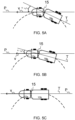
- the articulation angle ⁇ should be zero when the articulated vehicle 10 has moved sufficiently forward such that the wheels of the trailer unit 10b are at a position where the pivot joint 15 is located in FIG. 5A .
- FIG. 5b the articulated vehicle 10 has moved a distance forward and the articulation angle ⁇ is reduced compared to the articulation angle ⁇ of FIG. 5B .
- the direction d is unchanged and the articulated vehicle 10 is moving along the same tractor unit axis P as in FIG. 5A .
- the angular speed ⁇ will decrease as the articulation angle ⁇ approaches zero and, when the articulation angle ⁇ is zero, see FIG. 5C , the angular speed ⁇ will be zero.
- the tractor unit axis P and the trailing unit axis T coincide.
- FIG. 6A A corresponding example as the one presented with reference to FIG. 5A, FIG. 5B and FIG. 5C is shown in FIG. 6A, FIG. 6B and FIG. 6C , for a reversing articulated vehicle.
- an operator of the articulated vehicle 10 lets go of (releases) a SIU 25 controlling the steering system 20 of the articulated vehicle 10.
- the angular speed ⁇ is determined such that the direction d of the trailing unit 10b is maintained.
- the articulation angle ⁇ should be zero when the articulated vehicle 10 has moved sufficiently backwards such that the wheels of the tractor unit 10a are at a position where the pivot joint 15 is located in FIG. 6A .
- a distance d 10a (see FIG. 1 ) from a wheel axis of the tractor unit 10a to the pivot joint 15 is known
- the angular speed ⁇ may be determined as presented in reference to FIG. 5A, FIG. 5B and FIG. 5C .
- the angular speed ⁇ may be determined as presented above in the forward moving examples, e.g. in reference to FIG. 5A, FIG. 5B and FIG. 5C .
- the StC torque 231 may be determined as explained in reference to FIG. 4 and the pivot joint torque 261 may be controlled as explained in reference to FIG. 4 .
- time series plots of the speed s of the articulated vehicle 10 are shown along a common time axis t.
- the time series plots in FIG. 7 may be interpreted as describing the maneuvering of the articulated vehicles 10 in FIG. 5A, FIG. 5B and FIG. 5C or in FIG. 6A, FIG. 6B and FIG. 6C .
- the SIU 25 is released and the articulation angle ⁇ is negative.
- a positive angular speed ⁇ is determined that gradually decreases as the articulation angle ⁇ approaches zero.
- the speed s and the direction d of the articulated vehicle 10 are constant.
- FIG. 8 corresponding time series plots as those presented in FIG. 7 are shown along a common time axis t.
- an operator of the articulated vehicle 10 performs some more maneuvering than the operator in FIG. 7 .
- the articulated vehicle is moving forward with an articulation angle ⁇ being substantially zero.
- the articulation angle ⁇ increases. This may be due to the operator controlling the SIU 25 to provide a wanted articulation angle ⁇ changing the direction d positively. Responsive to the articulation angle ⁇ deviating from zero, a negative angular speed ⁇ is applied to the steering system 20. The angular speed ⁇ increases in magnitude with the articulation angle ⁇ . Assuming a steering wheel SIU 25 capable of providing haptic feedback to the operator, the operator will feel/experience the evolution of angular speed ⁇ by the SIU 25 as being heavier/harder to rotate. This is similar to the operation of Ackermann steering where steering will be heavier/harder the more the wheel is turned.
- the operator stops rotating the SIU 25 and keeps it at a constant steering angle, thereby providing a constant wanted articulation angle ⁇ .
- the articulation angle ⁇ is constant and so is the angular speed ⁇ .
- the direction d of the articulated vehicle 10 keeps changing at a constant pace.
- the operator accelerates the articulated vehicle 10 increasing the speed s of the articulated vehicle 10.
- the articulation angle ⁇ is kept constant, but due to the increase in speed, the angular speed ⁇ increases.
- an increased torque will be exerted on the SIU 25 making it heavier/harder for the operator to maintain the constant steering angle and thereby provide a constant wanted articulation angle ⁇ . This is similar to the operation of Ackermann steering where steering will be heavier at increased speeds.
- a fourth point in time T4 acceleration of the articulated vehicle 10 is stopped and the speed s is kept constant.
- the operator rotates the SIU 25 in an opposite direction to before, changing the steering angle and thereby the wanted articulation angle ⁇ .
- the articulation angle ⁇ changes from positive to negative and the direction d of the articulated vehicle 10 starts to decrease. That is to say, the articulated vehicle 10 is starting to turn back.
- the angular speed ⁇ tracks the articulation angle ⁇ and changes from negative to positive at a time the articulation angle ⁇ changes from positive to negative.
- the operator stops moving/rotating the SIU 25 and keeps the SIU 25 at a constant negative steering angle, thereby providing a constant negative wanted articulation angle ⁇ .
- the articulation angle ⁇ is constant and so is the angular speed ⁇ .
- the direction d of the articulated vehicle 10 keeps changing at a constant pace.
- the operator releases the SIU 25.
- the articulation angle ⁇ is controlled towards zero degrees at the angular speed ⁇ and the SIU 25 is rotated to provide a zero steering angle and zero wanted articulation angle ⁇ .
- the direction d of the articulated vehicle 10 is unchanged.
- the articulated vehicle 10 is controlled to continue at a constant direction d at a constant speed s.
- a computer system 100 comprising processing circuitry 110 is shown.
- the processing circuitry 110 is configured to obtain an articulation angle ⁇ of an articulated vehicle 10 and a velocity v of the articulated vehicle 10.
- the articulation angle ⁇ is controlled by a SIU 25 of a steering system 20 of the articulated vehicle 10.
- the processing circuitry 110 is further configured to, responsive to the articulation angle ⁇ deviating from 0°, determine an angular speed ⁇ for controlling the articulation angle ⁇ towards 0° based on the articulation angle ⁇ and a magnitude s of the velocity v such that a direction d of the velocity v is maintained.
- the processing circuitry 110 is further configured to determine the steer-to-center torque 231 for controlling the articulation angle ⁇ towards 0° based on the angular speed ⁇ , and to provide the steer-to-center torque 231 to the steering system 20 for control of the articulation angle ⁇ .
- the StC functionality presented in the presented disclosure may replace the selfcentering effect of for instance a car or any other vehicle with Ackermann steering. When a car is turning, and its steering wheel is released, it will continue travel in a straight line from where the steering wheel was released. The same effect is provided by examples of the present disclosure.
- Determining the angular velocity ⁇ as taught herein improves the steer-to-center functionality, making it easier to tune and to achieve the desired behavior of the articulated vehicle 10.
- the StC functionality further assists in keeping the articulated vehicle 10 stable when travelling straight (forward or backward).
- the teachings of the present disclosure are specifically effective when an articulated vehicle 10 is tele-operated from e.g. a rig station. Together with the camera feed from cameras mounted on the articulated vehicle 10, the StC torque 231 determined according to the present disclosure will assist the operator a lot, especially at low vehicle speeds s.
- the steering system 20 is a remote steering system 20, or at least the SIU 25 is a remote SIU.
- the steering system 20 and/or the SIU 25 may be comprised in the articulated vehicle 10.
- the articulated vehicle 10 may comprise the computer system 100 and/or the computer system 100 may comprise the steering system 20.
- the steering system 20 comprises the computer system 100.
- a method 300 is shown.
- the method 300 is for providing the StC torque 231 to the steering system 20 of an articulated vehicle 10.
- the method 300 may be a computer implemented method 300.
- the processing circuitry 110 of the computer system 100 may be configured to perform, or cause performance of, the method 300.
- the processing circuitry 21 of the steering system 20 may be configured to perform, or cause performance of, the method 300.
- the processing circuitry 110 of the computer system 100 and the processing circuitry 21 of the steering system 20 may be configured to co-operatively perform, or cause performance of, the method 300.
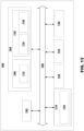
- the computer system 700 may comprise at least one computing device or electronic device capable of including firmware, hardware, and/or executing software instructions to implement the functionality described herein.
- the computer system 100 may be the computer system 100 introduced with reference to FIG. 1 .
- the computer system 700 may include processing circuitry 702 (e.g., processing circuitry including one or more processor devices or control units), a memory 704, and a system bus 706.
- the computer system 700 may include at least one computing device having the processing circuitry 702.
- the system bus 706 provides an interface for system components including, but not limited to, the memory 704 and the processing circuitry 702.
- the processing circuitry 702 may be or comprise the processing circuitry 110 of the computer system 100 introduced with reference to FIG. 1 , and/or the processing circuitry 21 of the steering system 20 introduced with reference to FIG.
- Example 20 The computer implemented method 300 of any one of examples 14 to 19, further comprising: controlling, by processing circuitry 110 of the computer system 100, the articulation angle ⁇ by controlling the steering system 20 to apply the wanted articulation torque 251 and the steer-to-center torque 231 to a steering actuator 23 of the steering system 20.
- Example 21 A computer program product 400 comprising program code 610 for performing, when executed by a processing circuitry 110, the method of any of examples 14 to 20.
- Example 22 A non-transitory computer-readable storage medium 500 comprising instructions, which when executed by a processing circuitry 110, cause the processing circuitry 110 to perform the method of any of examples 14 to 20.
- Example 23 A processing circuitry 110 configured to cause: obtaining of an articulation angle ⁇ of an articulated vehicle 10 and a velocity v of the articulated vehicle 10, wherein the articulation angle ⁇ is controlled by a steering input unit, SIU, 25 of a steering system 20 of the articulated vehicle 10, responsive to the articulation angle ⁇ deviating from 0°, causing: determining of an angular speed ⁇ for controlling the articulation angle ⁇ towards 0° based on the articulation angle ⁇ and a magnitude s of the velocity v such that a direction d of the velocity v is maintained, determining of a steer-to-center torque 231 for controlling the articulation angle ⁇ towards 0° based on the angular speed ⁇ , and provisioning of the steer-to-center torque 231 to the steering system 20 for control of the articulation angle ⁇ .
Landscapes
- Engineering & Computer Science (AREA)
- Chemical & Material Sciences (AREA)
- Combustion & Propulsion (AREA)
- Transportation (AREA)
- Mechanical Engineering (AREA)
- Physics & Mathematics (AREA)
- Mathematical Physics (AREA)
- Steering Control In Accordance With Driving Conditions (AREA)
Priority Applications (2)
| Application Number | Priority Date | Filing Date | Title |
|---|---|---|---|
| EP23193771.5A EP4516640B1 (de) | 2023-08-28 | 2023-08-28 | Steuerung eines gelenkfahrzeugs |
| US18/779,344 US20250074509A1 (en) | 2023-08-28 | 2024-07-22 | Control of articulated vehicle |
Applications Claiming Priority (1)
| Application Number | Priority Date | Filing Date | Title |
|---|---|---|---|
| EP23193771.5A EP4516640B1 (de) | 2023-08-28 | 2023-08-28 | Steuerung eines gelenkfahrzeugs |
Publications (2)
| Publication Number | Publication Date |
|---|---|
| EP4516640A1 true EP4516640A1 (de) | 2025-03-05 |
| EP4516640B1 EP4516640B1 (de) | 2026-04-22 |
Family
ID=87847757
Family Applications (1)
| Application Number | Title | Priority Date | Filing Date |
|---|---|---|---|
| EP23193771.5A Active EP4516640B1 (de) | 2023-08-28 | 2023-08-28 | Steuerung eines gelenkfahrzeugs |
Country Status (2)
| Country | Link |
|---|---|
| US (1) | US20250074509A1 (de) |
| EP (1) | EP4516640B1 (de) |
Citations (3)
| Publication number | Priority date | Publication date | Assignee | Title |
|---|---|---|---|---|
| US20160002885A1 (en) * | 2014-07-03 | 2016-01-07 | Caterpillar Inc. | Dynamic deadband for automatic articulation |
| US20160280260A1 (en) * | 2013-10-16 | 2016-09-29 | Aleees Eco Ark Co. Ltd. | Active steering system for articulated bus |
| US20200056348A1 (en) * | 2018-08-17 | 2020-02-20 | Deere & Company | Vehicle auto turning control system |
-
2023
- 2023-08-28 EP EP23193771.5A patent/EP4516640B1/de active Active
-
2024
- 2024-07-22 US US18/779,344 patent/US20250074509A1/en active Pending
Patent Citations (3)
| Publication number | Priority date | Publication date | Assignee | Title |
|---|---|---|---|---|
| US20160280260A1 (en) * | 2013-10-16 | 2016-09-29 | Aleees Eco Ark Co. Ltd. | Active steering system for articulated bus |
| US20160002885A1 (en) * | 2014-07-03 | 2016-01-07 | Caterpillar Inc. | Dynamic deadband for automatic articulation |
| US20200056348A1 (en) * | 2018-08-17 | 2020-02-20 | Deere & Company | Vehicle auto turning control system |
Also Published As
| Publication number | Publication date |
|---|---|
| EP4516640B1 (de) | 2026-04-22 |
| US20250074509A1 (en) | 2025-03-06 |
Similar Documents
| Publication | Publication Date | Title |
|---|---|---|
| JP7550281B2 (ja) | 自動走行システム及び自動走行方法 | |
| US20260077810A1 (en) | Steering Control System | |
| US9969428B2 (en) | Trailer backup assist system with waypoint selection | |
| US11937526B2 (en) | Control device for work vehicle configured to travel autonomously | |
| US12012143B2 (en) | Electrified trailer with reverse assist function | |
| CN113195327A (zh) | 确定自驾驶车辆上的车轮滑移 | |
| CN109154817A (zh) | 自动行驶作业车辆 | |
| US20220379956A1 (en) | System and Method for Controlling Steering Torque of a Steering System of a Vehicle | |
| JP6964735B2 (ja) | 自動操舵システム | |
| CN112389438A (zh) | 一种车辆转向系统传动比的确定方法及装置 | |
| EP4516640B1 (de) | Steuerung eines gelenkfahrzeugs | |
| EP4289696A1 (de) | Schwerpunktbestimmungsvorrichtung und -verfahren | |
| JP2020147175A (ja) | 作業車両 | |
| US12071124B2 (en) | Work vehicle | |
| US12246785B2 (en) | Automated steering system during loss of traction | |
| EP4200177B1 (de) | Vorrichtung und verfahren zur steuerung eines prozesses | |
| US20260048746A1 (en) | Longitudinal slip control for steered axles of a vehicle | |
| US20260048747A1 (en) | Rotational speed control for steered axles of a vehicle | |
| SK1022017U1 (sk) | Zariadenie na riadenie cúvania jazdnej súpravy s prívesom/návesom |
Legal Events
| Date | Code | Title | Description |
|---|---|---|---|
| PUAI | Public reference made under article 153(3) epc to a published international application that has entered the european phase |
Free format text: ORIGINAL CODE: 0009012 |
|
| STAA | Information on the status of an ep patent application or granted ep patent |
Free format text: STATUS: REQUEST FOR EXAMINATION WAS MADE |
|
| 17P | Request for examination filed |
Effective date: 20250121 |
|
| AK | Designated contracting states |
Kind code of ref document: A1 Designated state(s): AL AT BE BG CH CY CZ DE DK EE ES FI FR GB GR HR HU IE IS IT LI LT LU LV MC ME MK MT NL NO PL PT RO RS SE SI SK SM TR |
|
| GRAP | Despatch of communication of intention to grant a patent |
Free format text: ORIGINAL CODE: EPIDOSNIGR1 |
|
| STAA | Information on the status of an ep patent application or granted ep patent |
Free format text: STATUS: GRANT OF PATENT IS INTENDED |
|
| RIC1 | Information provided on ipc code assigned before grant |
Ipc: B62D 12/00 20060101AFI20251031BHEP Ipc: B62D 6/00 20060101ALN20251031BHEP |
|
| INTG | Intention to grant announced |
Effective date: 20251117 |
|
| RIC1 | Information provided on ipc code assigned before grant |
Ipc: B62D 12/00 20060101AFI20251108BHEP Ipc: B62D 6/00 20060101ALN20251108BHEP |
|
| GRAS | Grant fee paid |
Free format text: ORIGINAL CODE: EPIDOSNIGR3 |
|
| GRAA | (expected) grant |
Free format text: ORIGINAL CODE: 0009210 |
|
| STAA | Information on the status of an ep patent application or granted ep patent |
Free format text: STATUS: THE PATENT HAS BEEN GRANTED |
|
| AK | Designated contracting states |
Kind code of ref document: B1 Designated state(s): AL AT BE BG CH CY CZ DE DK EE ES FI FR GB GR HR HU IE IS IT LI LT LU LV MC ME MK MT NL NO PL PT RO RS SE SI SK SM TR |
|
| REG | Reference to a national code |
Ref country code: CH Ref legal event code: F10 Free format text: ST27 STATUS EVENT CODE: U-0-0-F10-F00 (AS PROVIDED BY THE NATIONAL OFFICE) Effective date: 20260422 Ref country code: GB Ref legal event code: FG4D |