EP4516588A1 - Lighting control device - Google Patents
Lighting control device Download PDFInfo
- Publication number
- EP4516588A1 EP4516588A1 EP23811871.5A EP23811871A EP4516588A1 EP 4516588 A1 EP4516588 A1 EP 4516588A1 EP 23811871 A EP23811871 A EP 23811871A EP 4516588 A1 EP4516588 A1 EP 4516588A1
- Authority
- EP
- European Patent Office
- Prior art keywords
- signal
- light emitting
- emitting elements
- lamp
- lighting
- Prior art date
- Legal status (The legal status is an assumption and is not a legal conclusion. Google has not performed a legal analysis and makes no representation as to the accuracy of the status listed.)
- Granted
Links
Images




Classifications
-
- B—PERFORMING OPERATIONS; TRANSPORTING
- B60—VEHICLES IN GENERAL
- B60Q—ARRANGEMENT OF SIGNALLING OR LIGHTING DEVICES, THE MOUNTING OR SUPPORTING THEREOF OR CIRCUITS THEREFOR, FOR VEHICLES IN GENERAL
- B60Q1/00—Arrangement of optical signalling or lighting devices, the mounting or supporting thereof or circuits therefor
- B60Q1/26—Arrangement of optical signalling or lighting devices, the mounting or supporting thereof or circuits therefor the devices being primarily intended to indicate the vehicle, or parts thereof, or to give signals, to other traffic
- B60Q1/2607—Arrangement of optical signalling or lighting devices, the mounting or supporting thereof or circuits therefor the devices being primarily intended to indicate the vehicle, or parts thereof, or to give signals, to other traffic comprising at least two indicating lamps
-
- B—PERFORMING OPERATIONS; TRANSPORTING
- B60—VEHICLES IN GENERAL
- B60Q—ARRANGEMENT OF SIGNALLING OR LIGHTING DEVICES, THE MOUNTING OR SUPPORTING THEREOF OR CIRCUITS THEREFOR, FOR VEHICLES IN GENERAL
- B60Q1/00—Arrangement of optical signalling or lighting devices, the mounting or supporting thereof or circuits therefor
- B60Q1/26—Arrangement of optical signalling or lighting devices, the mounting or supporting thereof or circuits therefor the devices being primarily intended to indicate the vehicle, or parts thereof, or to give signals, to other traffic
- B60Q1/34—Arrangement of optical signalling or lighting devices, the mounting or supporting thereof or circuits therefor the devices being primarily intended to indicate the vehicle, or parts thereof, or to give signals, to other traffic for indicating change of drive direction
- B60Q1/38—Arrangement of optical signalling or lighting devices, the mounting or supporting thereof or circuits therefor the devices being primarily intended to indicate the vehicle, or parts thereof, or to give signals, to other traffic for indicating change of drive direction using immovably-mounted light sources, e.g. fixed flashing lamps
- B60Q1/381—Arrangement of optical signalling or lighting devices, the mounting or supporting thereof or circuits therefor the devices being primarily intended to indicate the vehicle, or parts thereof, or to give signals, to other traffic for indicating change of drive direction using immovably-mounted light sources, e.g. fixed flashing lamps with several light sources activated in sequence, e.g. to create a sweep effect
-
- B—PERFORMING OPERATIONS; TRANSPORTING
- B60—VEHICLES IN GENERAL
- B60Q—ARRANGEMENT OF SIGNALLING OR LIGHTING DEVICES, THE MOUNTING OR SUPPORTING THEREOF OR CIRCUITS THEREFOR, FOR VEHICLES IN GENERAL
- B60Q1/00—Arrangement of optical signalling or lighting devices, the mounting or supporting thereof or circuits therefor
- B60Q1/26—Arrangement of optical signalling or lighting devices, the mounting or supporting thereof or circuits therefor the devices being primarily intended to indicate the vehicle, or parts thereof, or to give signals, to other traffic
- B60Q1/44—Arrangement of optical signalling or lighting devices, the mounting or supporting thereof or circuits therefor the devices being primarily intended to indicate the vehicle, or parts thereof, or to give signals, to other traffic for indicating braking action or preparation for braking, e.g. by detection of the foot approaching the brake pedal
-
- B—PERFORMING OPERATIONS; TRANSPORTING
- B60—VEHICLES IN GENERAL
- B60Q—ARRANGEMENT OF SIGNALLING OR LIGHTING DEVICES, THE MOUNTING OR SUPPORTING THEREOF OR CIRCUITS THEREFOR, FOR VEHICLES IN GENERAL
- B60Q1/00—Arrangement of optical signalling or lighting devices, the mounting or supporting thereof or circuits therefor
- B60Q1/26—Arrangement of optical signalling or lighting devices, the mounting or supporting thereof or circuits therefor the devices being primarily intended to indicate the vehicle, or parts thereof, or to give signals, to other traffic
- B60Q1/46—Arrangement of optical signalling or lighting devices, the mounting or supporting thereof or circuits therefor the devices being primarily intended to indicate the vehicle, or parts thereof, or to give signals, to other traffic for giving flashing caution signals during drive, other than signalling change of direction, e.g. flashing the headlights or hazard lights
-
- B—PERFORMING OPERATIONS; TRANSPORTING
- B60—VEHICLES IN GENERAL
- B60Q—ARRANGEMENT OF SIGNALLING OR LIGHTING DEVICES, THE MOUNTING OR SUPPORTING THEREOF OR CIRCUITS THEREFOR, FOR VEHICLES IN GENERAL
- B60Q1/00—Arrangement of optical signalling or lighting devices, the mounting or supporting thereof or circuits therefor
- B60Q1/26—Arrangement of optical signalling or lighting devices, the mounting or supporting thereof or circuits therefor the devices being primarily intended to indicate the vehicle, or parts thereof, or to give signals, to other traffic
- B60Q1/50—Arrangement of optical signalling or lighting devices, the mounting or supporting thereof or circuits therefor the devices being primarily intended to indicate the vehicle, or parts thereof, or to give signals, to other traffic for indicating other intentions or conditions, e.g. request for waiting or overtaking
- B60Q1/52—Arrangement of optical signalling or lighting devices, the mounting or supporting thereof or circuits therefor the devices being primarily intended to indicate the vehicle, or parts thereof, or to give signals, to other traffic for indicating other intentions or conditions, e.g. request for waiting or overtaking for indicating emergencies
-
- B—PERFORMING OPERATIONS; TRANSPORTING
- B60—VEHICLES IN GENERAL
- B60Q—ARRANGEMENT OF SIGNALLING OR LIGHTING DEVICES, THE MOUNTING OR SUPPORTING THEREOF OR CIRCUITS THEREFOR, FOR VEHICLES IN GENERAL
- B60Q1/00—Arrangement of optical signalling or lighting devices, the mounting or supporting thereof or circuits therefor
- B60Q1/26—Arrangement of optical signalling or lighting devices, the mounting or supporting thereof or circuits therefor the devices being primarily intended to indicate the vehicle, or parts thereof, or to give signals, to other traffic
- B60Q1/44—Arrangement of optical signalling or lighting devices, the mounting or supporting thereof or circuits therefor the devices being primarily intended to indicate the vehicle, or parts thereof, or to give signals, to other traffic for indicating braking action or preparation for braking, e.g. by detection of the foot approaching the brake pedal
- B60Q1/448—Arrangement of optical signalling or lighting devices, the mounting or supporting thereof or circuits therefor the devices being primarily intended to indicate the vehicle, or parts thereof, or to give signals, to other traffic for indicating braking action or preparation for braking, e.g. by detection of the foot approaching the brake pedal specially adapted for vehicles with ABS
Definitions
- the present embodiment relates to a lighting control device for a lap unit including multiple light emitting device.
- a vehicle is equipped with various lamps, such as a stop lamp (brake lamp) that lights up when braking, and a turning signal lamp that is used when turning left or right or changing course.
- a stop lamp brake lamp
- turning signal lamps are provided one on each of the left and right sides of the vehicle, and are also used as a hazard lamp when both are flashed at the same time.
- a chain lighting type so-called flowing blinker, sequential blinker
- multiple light emitting elements are sequentially lit so as to look like flowing from the inside to the outside has become popular.
- a first signal that instructs sequential lighting to sequentially light the multiple light emitting elements one after another is inputted into a lighting control device that controls a lamp unit of the chain lighting type.
- a second signal that instructs rapid flashing to rapidly flash all the multiple light emitting elements is inputted as well as the first signal.
- the lighting control device in which both the first signal and the second signal are inputted, discriminates the inputted signal and then controls the lamp unit according to the result of the discrimination.
- it is effective to first start lighting of the lamp unit even when either the first signal or the second signal is received.
- one of the conceivable controlling scheme may first start, when some signal is received, sequentially lighting of the lamp unit, and discriminate the inputted signal during this lighting.
- the sequential lighting is maintained when the first signal is received and switches the sequential lighting to the rapid flashing when the second signal is received.
- the lamp unit is suddenly switched from the sequential lighting to the rapid flashing when the second signal is received. Consequently, the multiple light emitting elements in the lamp unit will all simultaneously flash at a high speed after being sequentially lit one after another in the middle, there is a risk that the function as an emergency braking indicator lamp is not sufficiently ensured. Therefore, the conventional controlling scheme needs to be improved in order to rationalize the lighting status of the lamp unit both when the multiple light emitting elements are sequentially lit one after another and when all the multiple light emitting elements are flashed.
- one of the objects of the present embodiment is to rationalize the lighting status of the lamp unit both when the multiple light emitting elements are sequentially lit one after another and when all the multiple light emitting elements are flashed.
- the first signal may be a signal that activates the lamp unit as a turning signal lamp used when the vehicle is turning left or right or a hazard lamp used when the vehicle is stopping or parking; and the second signal may be a signal that activates the lamp unit as an emergency braking display light used when the vehicle is emergency braking.
- the first signal may be a signal that activates the lamp unit as at least one of a stop lump and a high mount stop lamp used when the vehicle is braking at deceleration less than a threshold; and the second signal may be a signal that activates the lamp unit as an emergency braking display light used when the vehicle is braking at deceleration equal to or more than a threshold.
- This configuration makes it possible to rationalize the lighting status of the lamp unit serving as at least one of the stop lamp and the high mount stop lamp along with the emergency braking indicator lamp. Accordingly, the reliability of at least one of stop lamp and high mount stop lamp along with the emergency braking indicator lamp can be enhanced.
- the receiver may receive the first signal and the second signal through a common signal line.
- the first signal and the second signal are received though a common signal line as the above, it is difficult to discriminate the first signal and the second signal from each other as compared with cases where the first signal and the second signal are received through respective different signal lines.
- the present application example since all light emitting elements are first lit when either the first signal or the second signal is received described above, it is possible to avoid the sequential lighting during discriminating of the signal. This makes it possible to rationalize the lighting status of the lamp unit for both the sequential lighting and the rapid flashing even if it is difficult to discriminate the signal.
- using a common signal line for the first signal and the second signal can reduce the number of signal lines and can simplify wiring routing as compared with cases where dedicated signal lines are provided one for each of the first signal and the second signal.
- the controller may light, when the receiver receives the first signal, lights all the plurality of light emitting elements for a first time correlated with a wavelength of the first signal and then sequentially lights the plurality of light emitting elements one at a time, and may light when the receiver receives the second signal, lights all the plurality of light emitting elements for a second time shorter than the first time and then flashes all the plurality of light emitting elements.
- the lighting status of the lamp unit can be rationalized for both when the multiple light emitting elements are sequentially lit one after another and when the multiple light emitting elements are all flashed.
- a lighting control device 1 according to the first embodiment is applied to a vehicle 10 provided with lamp units 3 each including multiple light emitting elements 2.
- the present embodiment illustrates a vehicle 10 being a truck.
- a reference number is attached to only one of the multiple light emitting elements 2 provided in the each lamp unit 3.
- a lamp unit 3 is a lighting device of the chained lighting type that sequentially lights the multiple light emitting element 2 one after another.
- the lamp unit 3 of the present embodiment functions as a turning signal lamp (so-called flowing blinker, sequential blinker) used when the vehicle 10 turns left and right.
- the lamp unit 3 functioning as a turning signal lamp is disposed on each of the left and right sides in the front and rear faces of the vehicle 10.
- the lamp unit 3 may function as a hazard lamp used when vehicle 10 is parked or stopped.
- the multiple light emitting elements 2 are arranged along vehicle width direction (left-right direction) in the each lamp unit 3, for example.
- the present embodiment illustrates a lamp unit 3 in which ten light emitting elements 2 configured the same as one another are arranged along the vehicle width direction.
- the number and arrangement of the light emitting elements 2 in each lamp unit 3 are not limited to the examples shown here.
- the lamp unit 3 of the present embodiment also functions as an emergency braking indicator lamp used during emergency braking of the vehicle 10.
- the emergency braking indicator lamp flashes at a high frequency (high speed) during sudden braking of the vehicle 10 to alert the surroundings of the vehicle 10.
- the emergency braking indicator lamp is used, for example, during emergency braking of the vehicle 10 at deceleration equal to or more than a threshold Th.
- the lamp unit 3 when functions as a turning signal lamp, takes a sequential lighting manner in which the multiple light emitting elements 2 are sequential lit one after another, and when functioning as an emergency braking indicator lamp, takes a rapid flashing manner in which the multiple light emitting elements 2 all simultaneously flash rapidly.
- the lighting status of each lamp unit 3 is controlled by the lighting control device 1.
- the vehicle 10 of the present embodiment is further provided with stop lamps 7 and a high mount stop lamp 8 that are used during braking of the vehicle 10.
- the stop lamps 7 are arranged on the right and left sides of the rear face of the vehicle 10. Further, the high mount stop lamp 8 is disposed at a higher position than the stop lamps 7 at the rear face of the vehicle 10.
- FIG. 1 illustrates two stop lamps 7 arranged under the left and right lamp units 3 in the rear face of the vehicle 10, and one high mount stop lamp 8 arranged on the center of the upper end of the rear face of the vehicle 10.
- the stop lamps 7 and the high mount stop lamp 8 are controlled so as to light in accordance with a depressing operation of a non-illustrated brake pedal equipped in the driver's seat of the vehicle 10.
- the stop lamps 7 and the high mount stop lamp 8 are used, for example, during braking of vehicle 10 at deceleration less than the threshold Th.
- the stop lamps 7 are also referred to as braking lamps (brake lamps), and the high mount stop lamp 8 is also referred to as an auxiliary braking lamp.
- the vehicle 10 is provided with a first sensor 4 that detects a trigger to sequentially light a lamp unit 3, and a second sensor 5 that detects a trigger to rapidly flash the lamp unit 3.
- the first sensor 4 is, for example, a sensor that detects the position of the non-illustrated blinker lever (turn signal lever) arranged at the driver's seat of the vehicle 10.
- the second sensor 5 is, for example, a sensor that detects sudden braking of the vehicle 10. More specifically, the second sensor 5 may be a brake sensor that detects a sudden depression of the brake pedal, a front sensor that detects the possibility of a front collision of the vehicle 10 to activate the automatic brake system, a deceleration sensor that detects sudden deceleration of the vehicle 10, or the like.
- the first sensor 4 and the second sensor 5 are connected to the lighting control device 1 through a common (same) signal line 6.
- a trigger of the sequential lighting e.g., operation of the blinker lever to a predetermined position
- the first sensor 4 transmits a first signal Sa to the lighting control device 1 through the signal line 6.
- a trigger of rapid flashing e.g., a sudden depression of the brake pedal
- the second sensor 5 transmits a second signal Sb to the lighting control device 1 through the signal line 6.
- the first signal Sa and the second signal Sb are inputted into the lighting control device 1 through the common (same) signal line 6.
- the lighting control device 1 is an electronic control unit (e.g., VCU; Vehicle Control Unit) that collectively controls various devices mounted on the vehicle 10.
- the lighting control device 1 is configured as, for example, an LSI device or a built-in electronic device in which a microprocessor, a ROM, a RAM, and the like are integrated, and is connected to the communication line of an on-board network provided in the vehicle 10.
- the first sensor 4 and the second sensor 5 are connected to its input side
- the lamp units 3 are connected to its output side.
- the lighting control device 1 performs sequential lighting control that sequentially lights the lamp unit 3 and rapid flashing control that rapidly flashes the lamp unit 3 in response to the first signal Sa and the second signal Sb inputted from the first sensor 4 and the second sensor 5, respectively.
- the lighting control device 1 includes a receiver 11 and a controller 12 as elements for implementing the sequential lighting control and the rapid flashing control.
- the receiver 11 and the controller 12 may be provided as software or hardware, or may be provided as a function of a computer program executable by the lighting control device 1.
- the receiver 11 receives the first signal Sa and the second signal Sb.
- the receiver 11 of the present embodiment receives the first signal Sa and the second signal Sb through the common signal line 6 from the first sensor 4 and the second sensor 5, respectively.
- the first signal Sa of the present embodiment is a signal that activates the lamp unit 3 as the turning signal lamp.
- the second signal Sb of the present embodiment is a signal that activates the lamp unit 3 as the emergency braking indicator lamp.
- the first signal Sa can be said to be a signal instructing the sequential lighting of the lamp unit 3
- the second signal Sb can be said to be a signal instructing the rapid flashing of the lamp unit 3.
- the first signal Sa may be a signal that activates the lamp units 3 as hazard lamps.
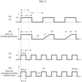
- FIG. 3 is a graph (timing chart) showing the waveforms of the first signal Sa and the second signal Sb, and the waveforms of the lighting status of the lamp unit 3 in accordance with these signals Sa and Sb.
- the first signal Sa and the second signal Sb of the present embodiment are both on-off signals. More specifically, the first signal Sa and the second signal Sb are pulse waves (rectangular waves) each having a duty ratio of 50% and have similar waveforms to each other. However, the first signal Sa and the second signal Sb have different wavelengths ⁇ a and ⁇ b, respectively, which also causes the respective pulse widths ⁇ a, ⁇ b to be different from each other.
- the graph (B) in FIG. 3 represents a lighting status of the lamp unit 3 which operates as a turning signal lamp in response to the first signal Sa. Further, the graph (D) in FIG. 3 represents a lighting status of the lamp unit 3 which operates as an emergency braking indicator lamp in response to the second signal Sb.
- the upward-sloping oblique line L1 represents a state in which the multiple light emitting elements 2 are sequentially lit.
- a horizontal line L2 having an amplitude A (A ⁇ 0) represents a state in which all the multiple light emitting elements 2 are lit
- the turning signal lamp flashes at a frequency of 1 to 2 Hz. Accordingly, the pulse width ⁇ a of the first signal Sa shown in the graph (A) is usually 250 to 333 ms. In relation to this, the lighting time Xa during which at least one light emitting element 2 is lit is normally 250 to 333 ms in each cycle of the sequential lighting of the lamp unit 3 shown in the graph (B).
- the emergency braking indicator lamp flashes at a frequency of 3 to 5 Hz. Accordingly, the pulse width ⁇ b of the second signal Sa shown in the graph (C) is usually 100 to 167 ms. In relation to this, the lighting time Xb during which all the light emitting elements 2 are simultaneously lit is normally 100 to 167 ms in each cycle of the rapid flashing of the lamp unit 3 shown in Graph (D).
- the wavelength lambda ⁇ b and the pulse width ⁇ b of the second signal Sb that instructs the rapid flashing are shorter than wavelength ⁇ a and the pulse width ⁇ a of the first signal Sa that instructs sequential lighting, respectively ( ⁇ b ⁇ a, ⁇ b ⁇ a). Further, consequently, the lighting time Xb of each cycle of the rapid flashing is shorter than the lighting time Xa of each cycle of the sequential lighting (Xb ⁇ Xa).
- the controller 12 controls the multiple light emitting elements 2 in accordance with the signal received by the receiver 11. Specifically, when some signal is received in the receiver 11, the receiver 12 discriminates whether the signal is the first signal Sa and the second signal Sb. Then, if the signal received by the receiver 11 is the first signal Sa, the controller 12 performs the sequential lighting control, and if the signal received by the receiver 11 is the second signal Sb, the controller 12 performs the rapid flashing control.
- the first signal Sa and the second signal Sb have respective different wavelength ⁇ a and ⁇ b and respective different pulse widths ⁇ a and ⁇ b, but have similar waveforms and are inputted into the receiver 11 through the common signal line 6, it is difficult to discriminate the first signal Sa and the second signal Sb from each other. That is, the first signal Sa and the second signal Sb inputted from the common signal line 6 cannot be discriminated on the basis of signal line 6 because there is no difference in signal line 6, and need to be discriminated on the basis of the differences of wavelengths ⁇ a and ⁇ b and pulse widths ⁇ a and ⁇ b.
- the first signal Sa and the second signal Sb have the same waveform as each other. Therefore, during at least this period P, it is difficult for the controller 12 to discriminate the first signal Sa and the second signal Sb from each other.
- the controller 12 lights all the multiple light emitting elements 2 first. In other words, even if the signal inputted into the receiver 11 is the first signal Sa, which instructs the sequential lighting, the controller 12 lights all the light emitting elements 2 first. This allows the controller 12 to reserve a time for discriminating the signal inputted into the receiver 11.
- the controller 12 determines that the signal is the first signal Sa, and if otherwise ( ⁇ Y), the controller 12 determines that the signal is the second signal Sb.
- the given value Y is preset as a value between the pulse width ⁇ a of the first signal Sa and the pulse width ⁇ b of the second signal Sb ( ⁇ b ⁇ Y ⁇ a).
- the discrimination may be based on the wavelengths or the frequencies correlated to pulse widths ⁇ .
- the controller 12 When the first signal Sa is received in the receiver 11, the controller 12 lights all the light emitting elements 2 as the above and after that sequentially lights the multiple light emitting elements 2 one after another. As shown in the graph (B) in FIG. 3 , when the first signal Sa is received in the receiver 11, the controller 12 of the present embodiment first lights all the multiple light emitting elements 2 for the first time Ta correlated with the wavelength ⁇ a (pulse width ⁇ a) of the first signal Sa, and after that, sequentially lights the multiple light emitting elements one after another.
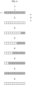
- FIG. 4 when the first signal Sa is inputted, all the light emitting elements 2 are simultaneously lit first for the first time Ta, then all the light emitting elements 2 are turned off, and after that the light emitting elements 2 are sequentially lit one after another.
- the sequentially lighting of the present embodiment begins with lighting all the light emitting elements 2, then turns off all the light emitting elements 2, and sequentially lights the light emitting elements 2 one after another.
- FIG. 4 and FIG. 5 to be described below represent a light emitting element 2 in the lighting status by halftone dots.
- FIG. 4 shows an example of the sequential lighting in which the multiple light emitting element 2 are sequentially lit so as to look like flowing from the right side (inside) toward the left side (outside) when the vehicle 10 is turning left.
- the controller 12 when the second signal Sb is received in the receiver 11, the controller 12 lights all the light emitting elements 2 as the above and after that flashes all the multiple light emitting elements 2.
- the controller 12 of the present embodiment first lights all the multiple light emitting elements 2 for the second time Tb correlated with the wavelength ⁇ b (pulse width ⁇ b) of the second signal Sb, and after that, flashes all the multiple light emitting elements 2. That is, when the second signal Sb is inputted, the controller 12 first lights all the light emitting elements 2 for the second time Tb shorter than the first time Ta.
- the controller 12 of this embodiment terminates the sequential lighting and the rapid flashing of the lamp unit 3 when a given termination condition is satisfied.
- the termination condition may be, for example, that first signal Sa or the second signal Sb are not received by the receiver 11 any longer.
- the termination condition for terminating the sequential lighting may be that the blinker lever has been returned to its normal position.
- the termination condition for terminating the rapid flashing may be that rapid flashing control has been performed for a predetermined time or longer.
- FIG. 6 is a flowchart illustrating an example of the procedure of the control implemented in the lighting control device 1. This flow is executed in the lighting control device 1 when the vehicle 10 is in a runnable condition (engine-on or power-on). It is assumed that, at the start of the flow, every light emitting element 2 of the lamp unit 3 is turned off.
- Step S1 first of all, whether or not the first signal Sa or the second signal Sb is received by the receiver 11 (Step S1). If neither the first signal Sa nor the second signal Sb is received (NO route in Step S1), the flow is returned. On the other hand, if the first signal Sa or the second signal Sb is received (YES route in Step S1), the multiple light emitting elements 2 is controlled, by the controller 12, so as to be all lit (Step S2). That is, even if the signal received by receiver 11 is either the first signal Sa or the second signal Sb, the controller 12 lights all the light emitting elements 2 of the lamp unit 3.
- Step S3 whether the signal received by the receiver 11 is the first signal Sa or the second signal Sb is determined in the controller 12 (Step S3).
- the sequential lighting control is performed by the controller 12 (Step S4). That is, in this case, the lamp unit 3 operates as a turning signal lamp.
- the sequential lighting control is terminated (Step S6), and the flow is returned.
- Step S7 the rapid flashing control is performed by the controller 12 (Step S7). That is, in this case, the lamp unit 3 operates as an emergency braking indicator lamp. After the predetermined termination condition is satisfied (YES route in Step S8), the rapid flashing control is terminated (Step S9), and the flow is returned.
- FIG. 8 is a graph (time chart) illustrating an example of waveforms according to a conventional controlling scheme.
- the graphs (A') and (C') of FIG. 8 represent the waveforms of the first signal Sa and the second signal Sb, respectively, and the same as the graphs (A) and (C) of FIG. 3 .
- the graph (B') of FIG. 8 represents the lighting status of the lamp unit 3 operating as a turning signal lamp in the conventional controlling scheme
- the graph (D') of FIG. 8 represents the lighting status of the lamp unit 3 operating as an emergency braking indicator lamp in the conventional controlling scheme.
- like reference signs designate the same or corresponding elements as those in FIG. 3 .
- the lamp unit 3 has been suddenly switched from the sequential lighting to the rapid flashing when the second signal Sb was received. For this reason, the multiple light emitting elements 2 have been all simultaneously flash at a high speed after being sequentially lit one after another in the middle. Accordingly, the conventional controlling scheme had a risk that the lamp unit 3 did not sufficiently exert the function as the emergency braking indicator lamp.
- the lighting control device 1 if the first signal Sa is received, the multiple light emitting elements 2 are all lit and then sequentially lit one after another, and if the second signal Sb is received, the multiple light emitting elements 2 are all lit and then are all flashed. Therefore, as shown in FIG. 4 , when the first signal Sa is received, the multiple light emitting elements 2 are all lit and then sequentially lit one after another. In other words, when the first signal Sa is received, after undergoing full-on and then full-off, the light emitting elements 2 are sequentially lit one after another. On the other hand, as shown in FIG. 5 , when the second signal Sb is received, after undergoing full-on, the light emitting elements 2 are flashed.
- the lighting control device 1 can rationalize the lighting status of the lamp unit 3 both when the sequentially lighting that sequentially lights the multiple light emitting elements 2 one after another and when the rapid flashing that flashes all the multiple light emitting elements 2.
- the lighting status of the lamp unit 3 serving as either the turning signal lamp or the emergency braking indicator lamp can be rationalized. Consequently, the reliability of the turning signal lamp and the emergency braking indicator lamp can be enhanced.
- the first signal Sa and the second signal Sb are signals to activate the lamp unit 3 to be the hazard lamp and the emergency braking indicator lamp, respectively, the lighting status of the lamp unit 3 as either the hazard lamp or the emergency braking indicator lamp can be rationalized. Thus, the reliability of the hazard lamp and the emergency braking indicator lamp can be enhanced.
- the lighting control device 1 since all light emitting elements 2 are first lit when either the first signal Sa or the second signal Sb is received as described above, it is possible to avoid the sequential lighting during the discrimination of the signal. This makes it possible to rationalize the lighting status of the lamp unit 3 for both the sequential lighting and the rapid flashing even if it is difficult to discriminate the signal during the period P shown in FIG. 3 .
- using the common signal line 6 for the first signal Sa and the second signal Sb can reduce the number of signal lines and can simplify wiring routing as compared with the case where dedicated signal lines are provided one for each of the first signal Sa and the second signal Sb.
- the lamp unit 3 is a lighting device (e.g., turning signal lamp or hazard lamps) provided on each of the front and rear faces of the vehicle 10, the sequential lighting and the rapid flashing can be performed to the forward side and the rear side of the vehicle 10. This makes it possible to notify the proceeding vehicle and the oncoming vehicles by the sequential lighting and the rapid flashing as well as the following vehicle, it is possible enhance the notification of both the sequential lighting and the rapid flashing to the surroundings.
- a lighting device e.g., turning signal lamp or hazard lamps
- a lighting control device 1' according to a second embodiment is different from the lighting control device 1 according to the first embodiment described above in the point that the lamp unit 3 to be controlled functions as at least one of a stop lamp, not a turning signal lamp, and a high mount stop lamp, but the remaining of the lighting control device 1' is the same as the lighting control device 1.
- like reference numbers designate the same or similar elements or parts described in the above embodiment and repetitious description is omitted here.
- the lamp unit 3 of the present embodiment is provided as the stop lamp and the high mount stop lamp described in the first embodiment.
- the vehicle 10 of the present embodiment is provided with two types of lamp units 3, i.e., a lamp unit 3A functioning as a stop lamp and a lamp unit 3B functioning as a high mount stop lamp.
- a lamp unit 3A functioning as a stop lamp and a lamp unit 3B functioning as a high mount stop lamp.
- these lamp units 3A and 3B collectively referred to as a "lamp unit 3".
- the lamp units 3A each functioning as the stop lamps are arranged on the right and left sides of the rear face of the vehicle 10. Further, the lamp unit 3B functioning as the high mount stop lamp is disposed at a higher position than the stop lamps 7 on the rear face of the vehicle 10.
- FIG. 7 illustrates the lamp units 3A and 3B arranged at the same positions as the stop lamps and the high mount stop lamp described in the first embodiment.
- the lamp unit 3 when functioning as at least one of the stop lamp and a high mount stop lamp, takes the sequential lighting manner, and when functioning as an emergency braking indicator lamp, takes the rapid flashing manner.
- the lighting status of each lamp unit 3 is controlled by the lighting control device 1'.
- the vehicle 10 of this embodiment is provided with turning signal lamps 9 used when the vehicle 10 turns left and right.
- the turning signal lamp 9 is disposed on each of the left and right sides of the front and rear faces of the vehicle 10.
- the lighting status of the turning signal lamps 9 is controlled, for example, in response to the operation of the blinker lever.
- the turning signal lamps 9 of the present embodiment do not have to be of a chain lighting type.
- the turning signal lamps 9 may also be used as a hazard lamp used when the vehicle 10 is parked or stopped.
- the control configuration of the lighting control device 1' is the same as that of the first embodiment described above. This means that, also in the lighting control device 1', the receiver 11 receives the first signal Sa and the second signal Sb. Further, when the first signal Sa is received in the receiver 11, the controller 12 lights all the light emitting elements 2 and after that, sequentially lights the multiple light emitting elements 2 one after another. On the other hand, when the second signal Sb is received in the receiver 11, the controller 12 lights all the light emitting elements 2 and after that, flashes all the multiple light emitting elements 2.
- the first signal Sa of the present embodiment is a signal that activates the lamp unit 3 as a stop lamp and a high mount stop lamp used when the vehicle is braking at deceleration less than the threshold Th.
- a second signal Sb of the present embodiment is a signal that activates the lamp unit 3 as an emergency braking indicator lamp used when the vehicle is emergency braking at deceleration equal to or more than the threshold Th.
- the first signal Sa can be said to be a signal instructing the sequential lighting of the lamp unit 3
- the second signal Sb can be said to be a signal instructing the rapid flashing of the lamp unit 3.
- the threshold Th is set in advance to be deceleration that can be regarded as sudden deceleration. In the case of emergency braking where the deceleration of the vehicle 10 is equal to or more than the threshold Th, the notification to the following vehicle becomes particularly critical to avoid bumping of the following vehicle.
- the first signal Sa is a signal that activates the lamp unit 3 as at least one of a stop lamp and a high mount stop lamp
- the second signal Sb is a signal that activates the lamp unit 3 as an emergency braking indicator lamp.
- the light emitting elements 2 are sequentially lit one after another after undergoing full-on and then full-off, the sequential lighting can be appropriately accomplished, and the light intensity at the start of the sequentially lighting is ensured by full-on, so that the clarity can be enhanced.
- the lighting control device 1' of the present embodiment also makes it possible to rationalize the lighting status of the lamp unit 3 when both the sequential lighting and the rapid flashing. That is, the lighting status of the lamp unit 3 can be rationalized when serving as at least one of the stop lamp and the high mount stop lamp along with the emergency braking indicator lamp. Accordingly, the reliability of at least one of stop lamp and high mount stop lamp along with the emergency braking indicator lamp can be enhanced.
- the same configuration of the lighting control device 1' of the present embodiment as the first embodiment obtains the same actions and effects as those of the first embodiment.
- the waveforms shown in FIG. 3 are exemplary. It is sufficient that the first signal Sa is any signal that instructs the sequential lighting of the lamp unit 3, and its application thereof is not limited to the turning signal lamp, the hazard lamps, the stop lamp, and the high mount stop lamp described the above. Similarly, it is sufficient that the second signal Sb is a signal that instructs flashing at a shorter wavelength (at a higher frequency, more rapidly) than the first signal Sa, and the application thereof is not limited to the above emergency braking indicator lamp.
- the receiver 11 may receive the first signal Sa and the second signal Sb from respective different signal lines.
- the senders of the first signal Sa and the second signal Sb may be devices except for the first sensor 11 and the second sensor 12.
- each of the various devices such as the lamp units 3, the stop lamps 7, the high mount stop lamp 8, and the turning signal lamp 9 provided in the vehicle 10 are not limited to those described in the above examples.
- the vehicle 10 is not limited to a truck, and may alternatively be exemplified by a bus, a passenger car, a motorbike, or the like.
- the lighting control device according to any one of appendices 1-3, wherein: the receiver receives the first signal and the second signal through a common signal line.
Landscapes
- Engineering & Computer Science (AREA)
- Mechanical Engineering (AREA)
- Lighting Device Outwards From Vehicle And Optical Signal (AREA)
Abstract
Description
- The present embodiment relates to a lighting control device for a lap unit including multiple light emitting device.
- A vehicle is equipped with various lamps, such as a stop lamp (brake lamp) that lights up when braking, and a turning signal lamp that is used when turning left or right or changing course. Generally, turning signal lamps are provided one on each of the left and right sides of the vehicle, and are also used as a hazard lamp when both are flashed at the same time. As a turning signal lamp, a chain lighting type (so-called flowing blinker, sequential blinker) in which multiple light emitting elements are sequentially lit so as to look like flowing from the inside to the outside has become popular.
- In recent years, a technique has been developed which uses, when the hard braking by harsh depressing operation of the braking pedal or by the automatic braking system, the stop lamp or the turning signal lamps (hazard lamps) also as emergency braking indicator lamps by flashing the stop lamps or the turning signal lamps at a high frequency (i.e., rapidly) (e.g., see
Patent Documents 1 and 2). Such emergency braking indicator lamps can notify a following vehicle of hard deceleration of the own vehicle, and therefore can prevent the following vehicle from bumping. -
- [Patent Document 1]
Japanese Laid-Open Patent Publication No. 2017-24487 - [Patent Document 2]
Japanese Laid-Open Patent Publication No. 2020-82942 - Incidentally, into a lighting control device that controls a lamp unit of the chain lighting type, a first signal that instructs sequential lighting to sequentially light the multiple light emitting elements one after another is inputted. On the other hand, into a lighting control device that controls a lamp unit of the chain lighting type also used for emergency braking indicator lamps, a second signal that instructs rapid flashing to rapidly flash all the multiple light emitting elements is inputted as well as the first signal.
- The lighting control device, in which both the first signal and the second signal are inputted, discriminates the inputted signal and then controls the lamp unit according to the result of the discrimination. However, in order to enhance the responsiveness to the inputted signal, it is effective to first start lighting of the lamp unit even when either the first signal or the second signal is received. For example, one of the conceivable controlling scheme may first start, when some signal is received, sequentially lighting of the lamp unit, and discriminate the inputted signal during this lighting. In such a controlling scheme, on the basis of the result of the discrimination, the sequential lighting is maintained when the first signal is received and switches the sequential lighting to the rapid flashing when the second signal is received.
- However, in the above-described controlling scheme, the lamp unit is suddenly switched from the sequential lighting to the rapid flashing when the second signal is received. Consequently, the multiple light emitting elements in the lamp unit will all simultaneously flash at a high speed after being sequentially lit one after another in the middle, there is a risk that the function as an emergency braking indicator lamp is not sufficiently ensured. Therefore, the conventional controlling scheme needs to be improved in order to rationalize the lighting status of the lamp unit both when the multiple light emitting elements are sequentially lit one after another and when all the multiple light emitting elements are flashed.
- With the foregoing problems in view, one of the objects of the present embodiment is to rationalize the lighting status of the lamp unit both when the multiple light emitting elements are sequentially lit one after another and when all the multiple light emitting elements are flashed.
- The present embodiments developed in order to solve at least part of the above problems, and the following embodiments can be achieved as application examples.
- (1) A lighting control device of the present application example controls a lamp unit including a plurality of light emitting elements in a vehicle, and includes a receiver that receives a first signal and a second signal having a wavelength shorter than a wavelength of the first signal; and a controller that, when the receiver receives the first signal, lights all the plurality of light emitting elements and then sequentially lights the plurality of light emitting elements one after another, and when the receiver receives the second signal, lights all the plurality of light emitting elements and then flashes all the plurality of light emitting elements.
- According to this application example, even when either the first signal or the second signal is received, lighting all the light emitting elements first makes it possible to prevent the sequential lighting from being suddenly switched to rapid flashing when the second signal is received. Therefore, it is possible to rationalize the lighting status of the lamp unit both when the sequentially lighting that sequentially lights the multiple light emitting elements one after another and when the rapid flashing that flashes all the multiple light emitting elements.
- (2) In the lighting control device of the present application example, the first signal may be a signal that activates the lamp unit as a turning signal lamp used when the vehicle is turning left or right or a hazard lamp used when the vehicle is stopping or parking; and the second signal may be a signal that activates the lamp unit as an emergency braking display light used when the vehicle is emergency braking.
- According to this configuration, it is possible to rationalize the lighting status of a lamp unit serving as either the turning signal lamp or the hazard lamp along with the emergency braking indicator lamp. Thus, the reliability of r the turning signal lamp or the hazard lamp along with the emergency braking indicator lamp can be enhanced.
- (3) In the lighting control device of the present application example, the first signal may be a signal that activates the lamp unit as at least one of a stop lump and a high mount stop lamp used when the vehicle is braking at deceleration less than a threshold; and the second signal may be a signal that activates the lamp unit as an emergency braking display light used when the vehicle is braking at deceleration equal to or more than a threshold.
- This configuration makes it possible to rationalize the lighting status of the lamp unit serving as at least one of the stop lamp and the high mount stop lamp along with the emergency braking indicator lamp. Accordingly, the reliability of at least one of stop lamp and high mount stop lamp along with the emergency braking indicator lamp can be enhanced.
- (4) In the lighting control device of the present application example, the receiver may receive the first signal and the second signal through a common signal line.
- When the first signal and the second signal are received though a common signal line as the above, it is difficult to discriminate the first signal and the second signal from each other as compared with cases where the first signal and the second signal are received through respective different signal lines. In contrast, in the present application example, since all light emitting elements are first lit when either the first signal or the second signal is received described above, it is possible to avoid the sequential lighting during discriminating of the signal. This makes it possible to rationalize the lighting status of the lamp unit for both the sequential lighting and the rapid flashing even if it is difficult to discriminate the signal. In addition, using a common signal line for the first signal and the second signal can reduce the number of signal lines and can simplify wiring routing as compared with cases where dedicated signal lines are provided one for each of the first signal and the second signal.
- (5) In the lighting control device of the present application example, the controller may light, when the receiver receives the first signal, lights all the plurality of light emitting elements for a first time correlated with a wavelength of the first signal and then sequentially lights the plurality of light emitting elements one at a time, and may light when the receiver receives the second signal, lights all the plurality of light emitting elements for a second time shorter than the first time and then flashes all the plurality of light emitting elements.
- According to this configuration, it is possible to perform the full-on of the light emitting elements when the rapid flashing shorter than when the sequential lighting. Therefore, the lighting status of the lamp unit in the rapid flashing can be rationalized.
- According to the present embodiment, the lighting status of the lamp unit can be rationalized for both when the multiple light emitting elements are sequentially lit one after another and when the multiple light emitting elements are all flashed.
-
- [
FIG. 1] FIG. 1 is a diagram showing a rear face applied with a lighting control device according to a first embodiment; - [
FIG. 2] FIG. 2 is a block diagram showing the lighting control device ofFIG. 1 ; - [
FIG. 3] FIG. 3 is a graph (time chart) showing a lighting status of a lamp unit controlled with a first signal and a second signal by the lighting control device ofFIG. 1 ; - [
FIG. 4] FIG. 4 is a schematic diagram showing an example of sequential lighting of the lamp unit by the lighting control device ofFIG. 1 ; - [
FIG. 5] FIG. 5 is a schematic diagram showing an example of rapid flashing of the lamp unit by the lighting control device ofFIG. 1 ; - [
FIG. 6] FIG. 6 is a flow diagram illustrating an example of a procedure of control executed by the lighting control device ofFIG. 1 ; - [
FIG. 7] FIG. 7 is a diagram showing a rear face applied with a lighting control device according to a second embodiment; - [
FIG. 8] FIG. 8 is a graph (time chart) showing a lighting status of a lamp unit controlled with a first signal and a second signal in a traditional control manner; - An embodiment of the present disclosure will now be described with reference to the accompanying drawings. The following example is merely and there is no intention to exclude various modification and application of techniques not explicitly described in the embodiment. Each structure of the following embodiment can be variously modified without departing from the scope thereof, and can be selected or omitted according to requirement, or combined in an appropriate combination.
- As shown in
FIG. 1 , alighting control device 1 according to the first embodiment is applied to avehicle 10 provided withlamp units 3 each including multiplelight emitting elements 2. The present embodiment illustrates avehicle 10 being a truck. In the drawings, a reference number is attached to only one of the multiplelight emitting elements 2 provided in the eachlamp unit 3. - A
lamp unit 3 is a lighting device of the chained lighting type that sequentially lights the multiplelight emitting element 2 one after another. Thelamp unit 3 of the present embodiment functions as a turning signal lamp (so-called flowing blinker, sequential blinker) used when thevehicle 10 turns left and right. Thelamp unit 3 functioning as a turning signal lamp is disposed on each of the left and right sides in the front and rear faces of thevehicle 10. In addition to (or instead of) the turning signal lamp, thelamp unit 3 may function as a hazard lamp used whenvehicle 10 is parked or stopped. - The multiple
light emitting elements 2 are arranged along vehicle width direction (left-right direction) in the eachlamp unit 3, for example. The present embodiment illustrates alamp unit 3 in which tenlight emitting elements 2 configured the same as one another are arranged along the vehicle width direction. However, the number and arrangement of thelight emitting elements 2 in eachlamp unit 3 are not limited to the examples shown here. - The
lamp unit 3 of the present embodiment also functions as an emergency braking indicator lamp used during emergency braking of thevehicle 10. The emergency braking indicator lamp flashes at a high frequency (high speed) during sudden braking of thevehicle 10 to alert the surroundings of thevehicle 10. The emergency braking indicator lamp is used, for example, during emergency braking of thevehicle 10 at deceleration equal to or more than a threshold Th. - The
lamp unit 3, when functions as a turning signal lamp, takes a sequential lighting manner in which the multiplelight emitting elements 2 are sequential lit one after another, and when functioning as an emergency braking indicator lamp, takes a rapid flashing manner in which the multiplelight emitting elements 2 all simultaneously flash rapidly. The lighting status of eachlamp unit 3 is controlled by thelighting control device 1. - The
vehicle 10 of the present embodiment is further provided withstop lamps 7 and a highmount stop lamp 8 that are used during braking of thevehicle 10. Thestop lamps 7 are arranged on the right and left sides of the rear face of thevehicle 10. Further, the highmount stop lamp 8 is disposed at a higher position than thestop lamps 7 at the rear face of thevehicle 10.FIG. 1 illustrates twostop lamps 7 arranged under the left andright lamp units 3 in the rear face of thevehicle 10, and one highmount stop lamp 8 arranged on the center of the upper end of the rear face of thevehicle 10. - The
stop lamps 7 and the highmount stop lamp 8 are controlled so as to light in accordance with a depressing operation of a non-illustrated brake pedal equipped in the driver's seat of thevehicle 10. Thestop lamps 7 and the highmount stop lamp 8 are used, for example, during braking ofvehicle 10 at deceleration less than the threshold Th. Incidentally, thestop lamps 7 are also referred to as braking lamps (brake lamps), and the highmount stop lamp 8 is also referred to as an auxiliary braking lamp. - The
vehicle 10 is provided with afirst sensor 4 that detects a trigger to sequentially light alamp unit 3, and asecond sensor 5 that detects a trigger to rapidly flash thelamp unit 3. Thefirst sensor 4 is, for example, a sensor that detects the position of the non-illustrated blinker lever (turn signal lever) arranged at the driver's seat of thevehicle 10. Thesecond sensor 5 is, for example, a sensor that detects sudden braking of thevehicle 10. More specifically, thesecond sensor 5 may be a brake sensor that detects a sudden depression of the brake pedal, a front sensor that detects the possibility of a front collision of thevehicle 10 to activate the automatic brake system, a deceleration sensor that detects sudden deceleration of thevehicle 10, or the like. - The
first sensor 4 and thesecond sensor 5 are connected to thelighting control device 1 through a common (same)signal line 6. When detecting a trigger of the sequential lighting (e.g., operation of the blinker lever to a predetermined position), thefirst sensor 4 transmits a first signal Sa to thelighting control device 1 through thesignal line 6. Similarly, when detecting a trigger of rapid flashing (e.g., a sudden depression of the brake pedal), thesecond sensor 5 transmits a second signal Sb to thelighting control device 1 through thesignal line 6. Thus, the first signal Sa and the second signal Sb are inputted into thelighting control device 1 through the common (same)signal line 6. - The
lighting control device 1 is an electronic control unit (e.g., VCU; Vehicle Control Unit) that collectively controls various devices mounted on thevehicle 10. Thelighting control device 1 is configured as, for example, an LSI device or a built-in electronic device in which a microprocessor, a ROM, a RAM, and the like are integrated, and is connected to the communication line of an on-board network provided in thevehicle 10. - As shown in
FIG. 2 , in thelighting control device 1 of the present embodiment, thefirst sensor 4 and thesecond sensor 5 are connected to its input side, thelamp units 3 are connected to its output side. Thelighting control device 1 performs sequential lighting control that sequentially lights thelamp unit 3 and rapid flashing control that rapidly flashes thelamp unit 3 in response to the first signal Sa and the second signal Sb inputted from thefirst sensor 4 and thesecond sensor 5, respectively. - The
lighting control device 1 includes areceiver 11 and acontroller 12 as elements for implementing the sequential lighting control and the rapid flashing control. Thereceiver 11 and thecontroller 12 may be provided as software or hardware, or may be provided as a function of a computer program executable by thelighting control device 1. - The
receiver 11 receives the first signal Sa and the second signal Sb. Thereceiver 11 of the present embodiment receives the first signal Sa and the second signal Sb through thecommon signal line 6 from thefirst sensor 4 and thesecond sensor 5, respectively. The first signal Sa of the present embodiment is a signal that activates thelamp unit 3 as the turning signal lamp. Further, the second signal Sb of the present embodiment is a signal that activates thelamp unit 3 as the emergency braking indicator lamp. The first signal Sa can be said to be a signal instructing the sequential lighting of thelamp unit 3, and the second signal Sb can be said to be a signal instructing the rapid flashing of thelamp unit 3. When thelamp units 3 function as hazard lamps, the first signal Sa may be a signal that activates thelamp units 3 as hazard lamps. -
FIG. 3 is a graph (timing chart) showing the waveforms of the first signal Sa and the second signal Sb, and the waveforms of the lighting status of thelamp unit 3 in accordance with these signals Sa and Sb. As illustrated by graphs (A) and (C) inFIG. 3 , the first signal Sa and the second signal Sb of the present embodiment are both on-off signals. More specifically, the first signal Sa and the second signal Sb are pulse waves (rectangular waves) each having a duty ratio of 50% and have similar waveforms to each other. However, the first signal Sa and the second signal Sb have different wavelengths λa and λb, respectively, which also causes the respective pulse widths τa, τb to be different from each other. - The graph (B) in
FIG. 3 represents a lighting status of thelamp unit 3 which operates as a turning signal lamp in response to the first signal Sa. Further, the graph (D) inFIG. 3 represents a lighting status of thelamp unit 3 which operates as an emergency braking indicator lamp in response to the second signal Sb. In the graph (B), the upward-sloping oblique line L1 represents a state in which the multiplelight emitting elements 2 are sequentially lit. Further, the graphs (B) and (D), a horizontal line L2 having an amplitude A (A≠0) represents a state in which all the multiplelight emitting elements 2 are lit, and a horizontal line L3 having no amplitude A (A=0) represents a state in which all the multiplelight emitting elements 2 are unlit. - Generally, the turning signal lamp flashes at a frequency of 1 to 2 Hz. Accordingly, the pulse width τa of the first signal Sa shown in the graph (A) is usually 250 to 333 ms. In relation to this, the lighting time Xa during which at least one
light emitting element 2 is lit is normally 250 to 333 ms in each cycle of the sequential lighting of thelamp unit 3 shown in the graph (B). - On the other hand, the emergency braking indicator lamp flashes at a frequency of 3 to 5 Hz. Accordingly, the pulse width τb of the second signal Sa shown in the graph (C) is usually 100 to 167 ms. In relation to this, the lighting time Xb during which all the
light emitting elements 2 are simultaneously lit is normally 100 to 167 ms in each cycle of the rapid flashing of thelamp unit 3 shown in Graph (D). - As the above, the wavelength lambda λb and the pulse width τb of the second signal Sb that instructs the rapid flashing are shorter than wavelength λa and the pulse width τa of the first signal Sa that instructs sequential lighting, respectively (λb<λa, τb<τa). Further, consequently, the lighting time Xb of each cycle of the rapid flashing is shorter than the lighting time Xa of each cycle of the sequential lighting (Xb<Xa).
- The
controller 12 controls the multiplelight emitting elements 2 in accordance with the signal received by thereceiver 11. Specifically, when some signal is received in thereceiver 11, thereceiver 12 discriminates whether the signal is the first signal Sa and the second signal Sb. Then, if the signal received by thereceiver 11 is the first signal Sa, thecontroller 12 performs the sequential lighting control, and if the signal received by thereceiver 11 is the second signal Sb, thecontroller 12 performs the rapid flashing control. - However, as described above, since the first signal Sa and the second signal Sb have respective different wavelength λa and λb and respective different pulse widths τa and τb, but have similar waveforms and are inputted into the
receiver 11 through thecommon signal line 6, it is difficult to discriminate the first signal Sa and the second signal Sb from each other. That is, the first signal Sa and the second signal Sb inputted from thecommon signal line 6 cannot be discriminated on the basis ofsignal line 6 because there is no difference insignal line 6, and need to be discriminated on the basis of the differences of wavelengths λa and λb and pulse widths τa and τb. - However, as shown in
FIG. 3 , during the period P between the first time point t1 at which thereceiver 11 receives the first signal Sa or the second signal Sb and the second time point t2 at which time corresponding to the pulse width τb of the second signal Sb elapses from the first time point, the first signal Sa and the second signal Sb have the same waveform as each other. Therefore, during at least this period P, it is difficult for thecontroller 12 to discriminate the first signal Sa and the second signal Sb from each other. - As a solution to this, even when either the first signal Sa or the second signal Sb is received in
receiver 11, thecontroller 12 lights all the multiplelight emitting elements 2 first. In other words, even if the signal inputted into thereceiver 11 is the first signal Sa, which instructs the sequential lighting, thecontroller 12 lights all thelight emitting elements 2 first. This allows thecontroller 12 to reserve a time for discriminating the signal inputted into thereceiver 11. - Then, for example, when the pulse width τ of the received signal is equal to or more than a given value Y (τ≥Y), the
controller 12 determines that the signal is the first signal Sa, and if otherwise (τ<Y), thecontroller 12 determines that the signal is the second signal Sb. Here, the given value Y is preset as a value between the pulse width τa of the first signal Sa and the pulse width τb of the second signal Sb (τb<Y<τa). Instead of such discrimination based on the pulse widths τ, the discrimination may be based on the wavelengths or the frequencies correlated to pulse widths τ. - When the first signal Sa is received in the
receiver 11, thecontroller 12 lights all thelight emitting elements 2 as the above and after that sequentially lights the multiplelight emitting elements 2 one after another. As shown in the graph (B) inFIG. 3 , when the first signal Sa is received in thereceiver 11, thecontroller 12 of the present embodiment first lights all the multiplelight emitting elements 2 for the first time Ta correlated with the wavelength λa (pulse width τa) of the first signal Sa, and after that, sequentially lights the multiple light emitting elements one after another. - Accordingly, as shown in
FIG. 4 , when the first signal Sa is inputted, all thelight emitting elements 2 are simultaneously lit first for the first time Ta, then all thelight emitting elements 2 are turned off, and after that thelight emitting elements 2 are sequentially lit one after another. In contrast to a typical sequential lighting, which sequentially lights thelight emitting elements 2 from full-off to full-on, the sequentially lighting of the present embodiment begins with lighting all thelight emitting elements 2, then turns off all thelight emitting elements 2, and sequentially lights thelight emitting elements 2 one after another. Incidentally, inFIG. 4 andFIG. 5 to be described below represent alight emitting element 2 in the lighting status by halftone dots.FIG. 4 shows an example of the sequential lighting in which the multiplelight emitting element 2 are sequentially lit so as to look like flowing from the right side (inside) toward the left side (outside) when thevehicle 10 is turning left. - On the other hand, when the second signal Sb is received in the
receiver 11, thecontroller 12 lights all thelight emitting elements 2 as the above and after that flashes all the multiplelight emitting elements 2. As shown in the graph (D) inFIG. 3 , when the second signal Sb is received in thereceiver 11, thecontroller 12 of the present embodiment first lights all the multiplelight emitting elements 2 for the second time Tb correlated with the wavelength λb (pulse width τb) of the second signal Sb, and after that, flashes all the multiplelight emitting elements 2. That is, when the second signal Sb is inputted, thecontroller 12 first lights all thelight emitting elements 2 for the second time Tb shorter than the first time Ta. - Accordingly, as shown in
FIG. 5 , when the second signal Sb is inputted, all thelight emitting elements 2 are first lit in the same manner as performed when the first signal Sa is inputted. However, when the second signal Sb is inputted, full-on is executed only for a shorter time (second time Tb) less than the time when the first signal Sa is inputted, and then all thelight emitting element 2 flashes simultaneously (full-on and full-off are repeated). - The
controller 12 of this embodiment terminates the sequential lighting and the rapid flashing of thelamp unit 3 when a given termination condition is satisfied. The termination condition may be, for example, that first signal Sa or the second signal Sb are not received by thereceiver 11 any longer. Alternatively, the termination condition for terminating the sequential lighting may be that the blinker lever has been returned to its normal position. Further alternatively, the termination condition for terminating the rapid flashing may be that rapid flashing control has been performed for a predetermined time or longer. -
FIG. 6 is a flowchart illustrating an example of the procedure of the control implemented in thelighting control device 1. This flow is executed in thelighting control device 1 when thevehicle 10 is in a runnable condition (engine-on or power-on). It is assumed that, at the start of the flow, everylight emitting element 2 of thelamp unit 3 is turned off. - As shown in
FIG. 6 , first of all, whether or not the first signal Sa or the second signal Sb is received by the receiver 11 (Step S1). If neither the first signal Sa nor the second signal Sb is received (NO route in Step S1), the flow is returned. On the other hand, if the first signal Sa or the second signal Sb is received (YES route in Step S1), the multiplelight emitting elements 2 is controlled, by thecontroller 12, so as to be all lit (Step S2). That is, even if the signal received byreceiver 11 is either the first signal Sa or the second signal Sb, thecontroller 12 lights all thelight emitting elements 2 of thelamp unit 3. - Then, whether the signal received by the
receiver 11 is the first signal Sa or the second signal Sb is determined in the controller 12 (Step S3). Here, if the received signal is determined to be the first signal Sa (YES route in Step S3), the sequential lighting control is performed by the controller 12 (Step S4). That is, in this case, thelamp unit 3 operates as a turning signal lamp. After the predetermined termination condition is satisfied (YES route in Step S5), the sequential lighting control is terminated (Step S6), and the flow is returned. - On the other hand, if the received signal is determined to be the second signal Sb (NO route in Step S3), the rapid flashing control is performed by the controller 12 (Step S7). That is, in this case, the
lamp unit 3 operates as an emergency braking indicator lamp. After the predetermined termination condition is satisfied (YES route in Step S8), the rapid flashing control is terminated (Step S9), and the flow is returned. -
FIG. 8 is a graph (time chart) illustrating an example of waveforms according to a conventional controlling scheme. The graphs (A') and (C') ofFIG. 8 represent the waveforms of the first signal Sa and the second signal Sb, respectively, and the same as the graphs (A) and (C) ofFIG. 3 . In addition, the graph (B') ofFIG. 8 represents the lighting status of thelamp unit 3 operating as a turning signal lamp in the conventional controlling scheme, and the graph (D') ofFIG. 8 represents the lighting status of thelamp unit 3 operating as an emergency braking indicator lamp in the conventional controlling scheme. InFIG. 8 , like reference signs designate the same or corresponding elements as those inFIG. 3 . - As shown in
FIG. 8 , the conventional controlling scheme has first started, even when either the first signal Sa or the second signal Sb was inputted, the sequential lighting of thelamp unit 3 and discriminated the signal during the sequential lighting. That is, conventionally, even when either the first signal Sa or the second signal Sb was inputted, the sequential lighting of thelamp unit 3 has been started at the time point t1. Then, if the signal was continuously received after the above second time point t2, the input signal has been determined to be the first signal Sa and the sequential lighting has been maintained, but if the signal was interrupted after the above second time point t2, the input signal has been determined to be the second signal Sb and the sequential lighting has been switched to the rapid flashing. - Therefore, as shown in the graph (D'), in the conventional controlling scheme, the
lamp unit 3 has been suddenly switched from the sequential lighting to the rapid flashing when the second signal Sb was received. For this reason, the multiplelight emitting elements 2 have been all simultaneously flash at a high speed after being sequentially lit one after another in the middle. Accordingly, the conventional controlling scheme had a risk that thelamp unit 3 did not sufficiently exert the function as the emergency braking indicator lamp. - In contrast, in the
lighting control device 1, if the first signal Sa is received, the multiplelight emitting elements 2 are all lit and then sequentially lit one after another, and if the second signal Sb is received, the multiplelight emitting elements 2 are all lit and then are all flashed. Therefore, as shown inFIG. 4 , when the first signal Sa is received, the multiplelight emitting elements 2 are all lit and then sequentially lit one after another. In other words, when the first signal Sa is received, after undergoing full-on and then full-off, thelight emitting elements 2 are sequentially lit one after another. On the other hand, as shown inFIG. 5 , when the second signal Sb is received, after undergoing full-on, thelight emitting elements 2 are flashed. - As the above, even when either the first signal or the second signal is received, lighting all the
light emitting elements 2 first makes it possible to prevent the sequential lighting from being suddenly switched to the rapid flashing when the second signal Sb is received. In addition, since, when the first signal Sa is received, thelight emitting elements 2 are sequentially lit one after another after undergoing full-on and then full-off, the sequential lighting can be appropriately accomplished, and the light intensity at the start of the sequentially lighting is ensured by full-on, so that the clarity can be enhanced. Accordingly, thelighting control device 1 can rationalize the lighting status of thelamp unit 3 both when the sequentially lighting that sequentially lights the multiplelight emitting elements 2 one after another and when the rapid flashing that flashes all the multiplelight emitting elements 2. - If the first signal Sa and the second signal Sb are signals to activate the
lamp unit 3 to be the turning signal lamp and the emergency braking indicator lamp, respectively, the lighting status of thelamp unit 3 serving as either the turning signal lamp or the emergency braking indicator lamp can be rationalized. Consequently, the reliability of the turning signal lamp and the emergency braking indicator lamp can be enhanced. - In addition, if the first signal Sa and the second signal Sb are signals to activate the
lamp unit 3 to be the hazard lamp and the emergency braking indicator lamp, respectively, the lighting status of thelamp unit 3 as either the hazard lamp or the emergency braking indicator lamp can be rationalized. Thus, the reliability of the hazard lamp and the emergency braking indicator lamp can be enhanced. - When the first signal Sa and the second signal Sb are received through a common signal line, it is difficult to discriminate the first signal Sa and the second signal Sb from each other as compared with cases where the first signal Sa and the second signal Sb are received from respective different signal lines. Since the conventional controlling scheme has executed the sequential lighting when receiving some signal, the sequential lighting has been performed while the signal was being discriminated even when the second signal Sb was received, so that there has been a risk that the rapid flashing has not appropriately executed.
- In contrast, in the
lighting control device 1, since alllight emitting elements 2 are first lit when either the first signal Sa or the second signal Sb is received as described above, it is possible to avoid the sequential lighting during the discrimination of the signal. This makes it possible to rationalize the lighting status of thelamp unit 3 for both the sequential lighting and the rapid flashing even if it is difficult to discriminate the signal during the period P shown inFIG. 3 . In addition, using thecommon signal line 6 for the first signal Sa and the second signal Sb can reduce the number of signal lines and can simplify wiring routing as compared with the case where dedicated signal lines are provided one for each of the first signal Sa and the second signal Sb. - By lighting all the multiple
light emitting elements 2 for the first time Ta when the first signal Sa is received and by lighting all the multiplelight emitting elements 2 for the second time Tb shorter than the first time Ta when the second signal Sb is received, full-on of thelight emitting elements 2 when the rapid flashing can be accomplished for a shorter time than that performed when the sequentially lighting. Therefore, the lighting status of thelamp unit 3 in the rapid flashing can be further rationalized. - If the
lamp unit 3 is a lighting device (e.g., turning signal lamp or hazard lamps) provided on each of the front and rear faces of thevehicle 10, the sequential lighting and the rapid flashing can be performed to the forward side and the rear side of thevehicle 10. This makes it possible to notify the proceeding vehicle and the oncoming vehicles by the sequential lighting and the rapid flashing as well as the following vehicle, it is possible enhance the notification of both the sequential lighting and the rapid flashing to the surroundings. - As shown in
FIG. 7 , a lighting control device 1' according to a second embodiment is different from thelighting control device 1 according to the first embodiment described above in the point that thelamp unit 3 to be controlled functions as at least one of a stop lamp, not a turning signal lamp, and a high mount stop lamp, but the remaining of the lighting control device 1' is the same as thelighting control device 1. In the present embodiment, like reference numbers designate the same or similar elements or parts described in the above embodiment and repetitious description is omitted here. - The
lamp unit 3 of the present embodiment is provided as the stop lamp and the high mount stop lamp described in the first embodiment. Specifically, thevehicle 10 of the present embodiment is provided with two types oflamp units 3, i.e., alamp unit 3A functioning as a stop lamp and alamp unit 3B functioning as a high mount stop lamp. Hereinafter, when not distinguishing from each other, theselamp units lamp unit 3". - The
lamp units 3A each functioning as the stop lamps are arranged on the right and left sides of the rear face of thevehicle 10. Further, thelamp unit 3B functioning as the high mount stop lamp is disposed at a higher position than thestop lamps 7 on the rear face of thevehicle 10.FIG. 7 illustrates thelamp units - The
lamp unit 3, when functioning as at least one of the stop lamp and a high mount stop lamp, takes the sequential lighting manner, and when functioning as an emergency braking indicator lamp, takes the rapid flashing manner. The lighting status of eachlamp unit 3 is controlled by the lighting control device 1'. - The
vehicle 10 of this embodiment is provided with turningsignal lamps 9 used when thevehicle 10 turns left and right.
As described in the above first embodiment, the turningsignal lamp 9 is disposed on each of the left and right sides of the front and rear faces of thevehicle 10. The lighting status of the turningsignal lamps 9 is controlled, for example, in response to the operation of the blinker lever. The turningsignal lamps 9 of the present embodiment do not have to be of a chain lighting type. The turningsignal lamps 9 may also be used as a hazard lamp used when thevehicle 10 is parked or stopped. - The control configuration of the lighting control device 1' is the same as that of the first embodiment described above. This means that, also in the lighting control device 1', the
receiver 11 receives the first signal Sa and the second signal Sb. Further, when the first signal Sa is received in thereceiver 11, thecontroller 12 lights all thelight emitting elements 2 and after that, sequentially lights the multiplelight emitting elements 2 one after another. On the other hand, when the second signal Sb is received in thereceiver 11, thecontroller 12 lights all thelight emitting elements 2 and after that, flashes all the multiplelight emitting elements 2. - The first signal Sa of the present embodiment is a signal that activates the
lamp unit 3 as a stop lamp and a high mount stop lamp used when the vehicle is braking at deceleration less than the threshold Th. Further, a second signal Sb of the present embodiment is a signal that activates thelamp unit 3 as an emergency braking indicator lamp used when the vehicle is emergency braking at deceleration equal to or more than the threshold Th. Also in this embodiment, the first signal Sa can be said to be a signal instructing the sequential lighting of thelamp unit 3, and the second signal Sb can be said to be a signal instructing the rapid flashing of thelamp unit 3. The threshold Th is set in advance to be deceleration that can be regarded as sudden deceleration. In the case of emergency braking where the deceleration of thevehicle 10 is equal to or more than the threshold Th, the notification to the following vehicle becomes particularly critical to avoid bumping of the following vehicle. - As described above, in the present embodiment, the first signal Sa is a signal that activates the
lamp unit 3 as at least one of a stop lamp and a high mount stop lamp, and the second signal Sb is a signal that activates thelamp unit 3 as an emergency braking indicator lamp. With this configuration, like the first embodiment, even when either the first signal Sa or the second signal Sb is received, first lighting all thelight emitting elements 2 makes it possible to prevent the sequential lighting from being suddenly switched to the rapid flashing when the second signal Sb is received. In addition, since, when the first signal Sa is received, thelight emitting elements 2 are sequentially lit one after another after undergoing full-on and then full-off, the sequential lighting can be appropriately accomplished, and the light intensity at the start of the sequentially lighting is ensured by full-on, so that the clarity can be enhanced. - Accordingly, the lighting control device 1' of the present embodiment also makes it possible to rationalize the lighting status of the
lamp unit 3 when both the sequential lighting and the rapid flashing. That is, the lighting status of thelamp unit 3 can be rationalized when serving as at least one of the stop lamp and the high mount stop lamp along with the emergency braking indicator lamp. Accordingly, the reliability of at least one of stop lamp and high mount stop lamp along with the emergency braking indicator lamp can be enhanced. - In addition, the same configuration of the lighting control device 1' of the present embodiment as the first embodiment obtains the same actions and effects as those of the first embodiment.
- All of the waveforms shown in
FIG. 3 are exemplary. It is sufficient that the first signal Sa is any signal that instructs the sequential lighting of thelamp unit 3, and its application thereof is not limited to the turning signal lamp, the hazard lamps, the stop lamp, and the high mount stop lamp described the above. Similarly, it is sufficient that the second signal Sb is a signal that instructs flashing at a shorter wavelength (at a higher frequency, more rapidly) than the first signal Sa, and the application thereof is not limited to the above emergency braking indicator lamp. - The
receiver 11 may receive the first signal Sa and the second signal Sb from respective different signal lines. The senders of the first signal Sa and the second signal Sb may be devices except for thefirst sensor 11 and thesecond sensor 12. - The number and arrangement of each of the various devices, such as the
lamp units 3, thestop lamps 7, the highmount stop lamp 8, and the turningsignal lamp 9 provided in thevehicle 10 are not limited to those described in the above examples. Further, thevehicle 10 is not limited to a truck, and may alternatively be exemplified by a bus, a passenger car, a motorbike, or the like. - In relation to the above embodiment, the following appendices are further disclosed.
- A lighting control device that controls a lamp unit including a plurality of light emitting elements in a vehicle, the lighting control device comprising:
- a receiver that receives a first signal and a second signal having a wavelength shorter than a wavelength of the first signal; and
- a controller that, when the receiver receives the first signal, lights all the plurality of light emitting elements and then sequentially lights the plurality of light emitting elements one after another, and when the receiver receives the second signal, lights all the plurality of light emitting elements and then flashes all the plurality of light emitting elements.
- The lighting control device according to
appendix 1, wherein: - the first signal is a signal that activates the lamp unit as a turning signal lamp used when the vehicle is turning left or right or a hazard lamp used when the vehicle is stopping or parking; and
- the second signal is a signal that activates the lamp unit as an emergency braking display light used when the vehicle is emergency braking.
- The lighting control device according to
appendix 1, wherein: - the first signal is a signal that activates the lamp unit as at least one of a stop lump and a high mount stop lamp used when the vehicle is braking at deceleration less than a threshold; and
- the second signal is a signal that activates the lamp unit as an emergency braking display light used when the vehicle is braking at deceleration equal to or more than a threshold.
- The lighting control device according to any one of appendices 1-3, wherein:
the receiver receives the first signal and the second signal through a common signal line. - The lighting control device according to any one of appendices 1-4, wherein:
- the controller
- when the receiver receives the first signal, lights all the plurality of light emitting elements for a first time correlated with a wavelength of the first signal and then sequentially lights the plurality of light emitting elements one at a time, and
- when the receiver receives the second signal, lights all the plurality of light emitting elements for a second time shorter than the first time and then flashes all the plurality of light emitting elements.
-
- 1,1'
- lighting control device
- 2
- light emitting element
- 3,3A,3B
- lamp unit
- 4
- first sensor
- 5
- second sensor
- 6
- signal line
- 7
- stop lamp
- 8
- high mount stop lamp
- 9
- turning signal lamp
- 10
- vehicle
- 11
- receiver
- 12
- controller
- A
- amplitude
- L1
- oblique line
- L2
- horizontal line
- L3
- horizontal line
- P
- period
- Sa
- first signal
- Sb
- second signal
- t1
- first time point
- t2
- second time point
- Ta
- first time
- Tb
- second time
- Xa
- lighting time
- Xb
- lighting time
- Y
- given value
- λa
- wavelength
- λb
- wavelength
- τa
- pulse width
- τb
- pulse width
Claims (5)
- A lighting control device that controls a lamp unit including a plurality of light emitting elements in a vehicle, the lighting control device comprising:a receiver that receives a first signal and a second signal having a wavelength shorter than a wavelength of the first signal; anda controller that, when the receiver receives the first signal, lights all the plurality of light emitting elements and then sequentially lights the plurality of light emitting elements one after another, and when the receiver receives the second signal, lights all the plurality of light emitting elements and then flashes all the plurality of light emitting elements.
- The lighting control device according to claim 1, wherein:the first signal is a signal that activates the lamp unit as a turning signal lamp used when the vehicle is turning left or right or a hazard lamp used when the vehicle is stopping or parking; andthe second signal is a signal that activates the lamp unit as an emergency braking display light used when the vehicle is emergency braking.
- The lighting control device according to claim 1, wherein:the first signal is a signal that activates the lamp unit as at least one of a stop lump and a high mount stop lamp used when the vehicle is braking at deceleration less than a threshold; andthe second signal is a signal that activates the lamp unit as an emergency braking display light used when the vehicle is braking at deceleration equal to or more than a threshold.
- The lighting control device according to claim 1, wherein:
the receiver receives the first signal and the second signal through a common signal line. - The lighting control device according to claim 1, wherein:the controllerwhen the receiver receives the first signal, lights all the plurality of light emitting elements for a first time correlated with a wavelength of the first signal and then sequentially lights the plurality of light emitting elements one at a time, andwhen the receiver receives the second signal, lights all the plurality of light emitting elements for a second time shorter than the first time and then flashes all the plurality of light emitting elements.
Applications Claiming Priority (2)
| Application Number | Priority Date | Filing Date | Title |
|---|---|---|---|
| JP2022087079A JP7607005B2 (en) | 2022-05-27 | 2022-05-27 | Lighting control device |
| PCT/JP2023/019457 WO2023228999A1 (en) | 2022-05-27 | 2023-05-25 | Lighting control device |
Publications (3)
| Publication Number | Publication Date |
|---|---|
| EP4516588A1 true EP4516588A1 (en) | 2025-03-05 |
| EP4516588A4 EP4516588A4 (en) | 2025-05-07 |
| EP4516588B1 EP4516588B1 (en) | 2026-04-15 |
Family
ID=88919420
Family Applications (1)
| Application Number | Title | Priority Date | Filing Date |
|---|---|---|---|
| EP23811871.5A Active EP4516588B1 (en) | 2022-05-27 | 2023-05-25 | Lighting control device |
Country Status (4)
| Country | Link |
|---|---|
| EP (1) | EP4516588B1 (en) |
| JP (1) | JP7607005B2 (en) |
| CN (1) | CN119255935A (en) |
| WO (1) | WO2023228999A1 (en) |
Family Cites Families (8)
| Publication number | Priority date | Publication date | Assignee | Title |
|---|---|---|---|---|
| JP2009012554A (en) * | 2007-07-03 | 2009-01-22 | Koito Mfg Co Ltd | Lighting unit system for vehicle |
| KR102360132B1 (en) * | 2015-01-13 | 2022-02-07 | 주식회사 엘엑스세미콘 | Apparatus for rear combination lamp and method for controlling thereof |
| JP2017024487A (en) | 2015-07-17 | 2017-02-02 | いすゞ自動車株式会社 | Emergency braking indicator light control device |
| JP2017094757A (en) | 2015-11-18 | 2017-06-01 | 株式会社オートフレンド | Vehicular lighting fixture |
| KR20170082670A (en) * | 2016-01-06 | 2017-07-17 | 엘지전자 주식회사 | Lamp for vehicle and Vehicle including the same |
| KR20190063673A (en) * | 2017-11-30 | 2019-06-10 | 르노삼성자동차 주식회사 | Method for lighting turn signal lamps dynamically depending on traffic situations |
| JP7002320B2 (en) | 2017-12-21 | 2022-02-04 | 株式会社小糸製作所 | Vehicle lamp |
| JP2020082942A (en) | 2018-11-21 | 2020-06-04 | スタンレー電気株式会社 | Control device of light source, control method of light source, and vehicular lighting fixture |
-
2022
- 2022-05-27 JP JP2022087079A patent/JP7607005B2/en active Active
-
2023
- 2023-05-25 EP EP23811871.5A patent/EP4516588B1/en active Active
- 2023-05-25 CN CN202380042563.4A patent/CN119255935A/en active Pending
- 2023-05-25 WO PCT/JP2023/019457 patent/WO2023228999A1/en not_active Ceased
Also Published As
| Publication number | Publication date |
|---|---|
| JP7607005B2 (en) | 2024-12-26 |
| EP4516588A4 (en) | 2025-05-07 |
| WO2023228999A1 (en) | 2023-11-30 |
| EP4516588B1 (en) | 2026-04-15 |
| CN119255935A (en) | 2025-01-03 |
| JP2023174306A (en) | 2023-12-07 |
Similar Documents
| Publication | Publication Date | Title |
|---|---|---|
| US4127844A (en) | Vehicle strobe warning light system | |
| US8310357B2 (en) | After market sequential turn signal | |
| US10773640B2 (en) | Method and apparatus for automatically adjusting luminance of vehicle tail light | |
| EP3519246B1 (en) | Enhanced communication system for vehicle hazard lights | |
| JP2008143499A (en) | Rear lamp control method to prevent rear-end collision | |
| JP2009012554A (en) | Lighting unit system for vehicle | |
| US7808376B2 (en) | Continuous enhanced vehicle hazard warning lights | |
| EP4516588A1 (en) | Lighting control device | |
| JP4485901B2 (en) | Vehicle lamp | |
| KR101656685B1 (en) | Apparatus and method for controlling of automotive lamp | |
| JP2006069245A (en) | Warning light device for vehicles | |
| JP2008296743A (en) | Automatic braking system | |
| KR101536677B1 (en) | Vehicle Collision Prevention Apparatus | |
| KR102079237B1 (en) | Device and method for controlling vehicle light lamp | |
| CN110901522A (en) | Brake display device and method and vehicle | |
| JPH10315844A (en) | Light control device for vehicle | |
| JP7327267B2 (en) | Pedal mistake acceleration control device | |
| JPH0986274A (en) | Lighting failure backup device | |
| JP5598904B2 (en) | Brake light control device | |
| JP3224121U (en) | Vehicle thanks display device | |
| KR20240108635A (en) | A device of u-turn signal for a vehicle | |
| JP3224312U (en) | Vehicle thanks display device | |
| KR102949251B1 (en) | Apparatus and method for controlling automotive lamp | |
| JP2014015102A (en) | Safety lamp | |
| KR200431152Y1 (en) | Vehicle deceleration display device |
Legal Events
| Date | Code | Title | Description |
|---|---|---|---|
| STAA | Information on the status of an ep patent application or granted ep patent |
Free format text: STATUS: THE INTERNATIONAL PUBLICATION HAS BEEN MADE |
|
| PUAI | Public reference made under article 153(3) epc to a published international application that has entered the european phase |
Free format text: ORIGINAL CODE: 0009012 |
|
| STAA | Information on the status of an ep patent application or granted ep patent |
Free format text: STATUS: REQUEST FOR EXAMINATION WAS MADE |
|
| 17P | Request for examination filed |
Effective date: 20241126 |
|
| AK | Designated contracting states |
Kind code of ref document: A1 Designated state(s): AL AT BE BG CH CY CZ DE DK EE ES FI FR GB GR HR HU IE IS IT LI LT LU LV MC ME MK MT NL NO PL PT RO RS SE SI SK SM TR |
|
| REG | Reference to a national code |
Ref country code: DE Ref legal event code: R079 Free format text: PREVIOUS MAIN CLASS: B60Q0001460000 Ipc: B60Q0001260000 Ref country code: DE Ref legal event code: R079 Ref document number: 602023015466 Country of ref document: DE Free format text: PREVIOUS MAIN CLASS: B60Q0001460000 Ipc: B60Q0001260000 |
|
| A4 | Supplementary search report drawn up and despatched |
Effective date: 20250408 |
|
| RIC1 | Information provided on ipc code assigned before grant |
Ipc: B60Q 1/52 20060101ALI20250402BHEP Ipc: B60Q 1/44 20060101ALI20250402BHEP Ipc: B60Q 1/38 20060101ALI20250402BHEP Ipc: B60Q 1/46 20060101ALI20250402BHEP Ipc: B60Q 1/26 20060101AFI20250402BHEP |
|
| DAV | Request for validation of the european patent (deleted) | ||
| DAX | Request for extension of the european patent (deleted) | ||
| GRAP | Despatch of communication of intention to grant a patent |
Free format text: ORIGINAL CODE: EPIDOSNIGR1 |
|
| STAA | Information on the status of an ep patent application or granted ep patent |
Free format text: STATUS: GRANT OF PATENT IS INTENDED |
|
| INTG | Intention to grant announced |
Effective date: 20251114 |
|
| GRAS | Grant fee paid |
Free format text: ORIGINAL CODE: EPIDOSNIGR3 |
|
| GRAA | (expected) grant |
Free format text: ORIGINAL CODE: 0009210 |
|
| STAA | Information on the status of an ep patent application or granted ep patent |
Free format text: STATUS: THE PATENT HAS BEEN GRANTED |
|
| AK | Designated contracting states |
Kind code of ref document: B1 Designated state(s): AL AT BE BG CH CY CZ DE DK EE ES FI FR GB GR HR HU IE IS IT LI LT LU LV MC ME MK MT NL NO PL PT RO RS SE SI SK SM TR |
|
| P01 | Opt-out of the competence of the unified patent court (upc) registered |
Free format text: CASE NUMBER: UPC_APP_0008744_4516588/2026 Effective date: 20260305 |
|
| REG | Reference to a national code |
Ref country code: CH Ref legal event code: F10 Free format text: ST27 STATUS EVENT CODE: U-0-0-F10-F00 (AS PROVIDED BY THE NATIONAL OFFICE) Effective date: 20260415 |