EP4516547A1 - Support device for drive battery - Google Patents
Support device for drive battery Download PDFInfo
- Publication number
- EP4516547A1 EP4516547A1 EP23811534.9A EP23811534A EP4516547A1 EP 4516547 A1 EP4516547 A1 EP 4516547A1 EP 23811534 A EP23811534 A EP 23811534A EP 4516547 A1 EP4516547 A1 EP 4516547A1
- Authority
- EP
- European Patent Office
- Prior art keywords
- face
- battery
- projecting
- drive battery
- face part
- Prior art date
- Legal status (The legal status is an assumption and is not a legal conclusion. Google has not performed a legal analysis and makes no representation as to the accuracy of the status listed.)
- Pending
Links
Images




Classifications
-
- B—PERFORMING OPERATIONS; TRANSPORTING
- B60—VEHICLES IN GENERAL
- B60L—PROPULSION OF ELECTRICALLY-PROPELLED VEHICLES; SUPPLYING ELECTRIC POWER FOR AUXILIARY EQUIPMENT OF ELECTRICALLY-PROPELLED VEHICLES; ELECTRODYNAMIC BRAKE SYSTEMS FOR VEHICLES IN GENERAL; MAGNETIC SUSPENSION OR LEVITATION FOR VEHICLES; MONITORING OPERATING VARIABLES OF ELECTRICALLY-PROPELLED VEHICLES; ELECTRIC SAFETY DEVICES FOR ELECTRICALLY-PROPELLED VEHICLES
- B60L50/00—Electric propulsion with power supplied within the vehicle
- B60L50/50—Electric propulsion with power supplied within the vehicle using propulsion power supplied by batteries or fuel cells
- B60L50/60—Electric propulsion with power supplied within the vehicle using propulsion power supplied by batteries or fuel cells using power supplied by batteries
- B60L50/66—Arrangements of batteries
-
- B—PERFORMING OPERATIONS; TRANSPORTING
- B60—VEHICLES IN GENERAL
- B60K—ARRANGEMENT OR MOUNTING OF PROPULSION UNITS OR OF TRANSMISSIONS IN VEHICLES; ARRANGEMENT OR MOUNTING OF PLURAL DIVERSE PRIME-MOVERS IN VEHICLES; AUXILIARY DRIVES FOR VEHICLES; INSTRUMENTATION OR DASHBOARDS FOR VEHICLES; ARRANGEMENTS IN CONNECTION WITH COOLING, AIR INTAKE, GAS EXHAUST OR FUEL SUPPLY OF PROPULSION UNITS IN VEHICLES
- B60K1/00—Arrangement or mounting of electrical propulsion units
- B60K1/04—Arrangement or mounting of electrical propulsion units of the electric storage means for propulsion
-
- H—ELECTRICITY
- H01—ELECTRIC ELEMENTS
- H01M—PROCESSES OR MEANS, e.g. BATTERIES, FOR THE DIRECT CONVERSION OF CHEMICAL ENERGY INTO ELECTRICAL ENERGY
- H01M50/00—Constructional details or processes of manufacture of the non-active parts of electrochemical cells other than fuel cells, e.g. hybrid cells
- H01M50/20—Mountings; Secondary casings or frames; Racks, modules or packs; Suspension devices; Shock absorbers; Transport or carrying devices; Holders
- H01M50/233—Mountings; Secondary casings or frames; Racks, modules or packs; Suspension devices; Shock absorbers; Transport or carrying devices; Holders characterised by physical properties of casings or racks, e.g. dimensions
- H01M50/242—Mountings; Secondary casings or frames; Racks, modules or packs; Suspension devices; Shock absorbers; Transport or carrying devices; Holders characterised by physical properties of casings or racks, e.g. dimensions adapted for protecting batteries against vibrations, collision impact or swelling
-
- H—ELECTRICITY
- H01—ELECTRIC ELEMENTS
- H01M—PROCESSES OR MEANS, e.g. BATTERIES, FOR THE DIRECT CONVERSION OF CHEMICAL ENERGY INTO ELECTRICAL ENERGY
- H01M50/00—Constructional details or processes of manufacture of the non-active parts of electrochemical cells other than fuel cells, e.g. hybrid cells
- H01M50/20—Mountings; Secondary casings or frames; Racks, modules or packs; Suspension devices; Shock absorbers; Transport or carrying devices; Holders
- H01M50/249—Mountings; Secondary casings or frames; Racks, modules or packs; Suspension devices; Shock absorbers; Transport or carrying devices; Holders specially adapted for aircraft or vehicles, e.g. cars or trains
-
- H—ELECTRICITY
- H01—ELECTRIC ELEMENTS
- H01M—PROCESSES OR MEANS, e.g. BATTERIES, FOR THE DIRECT CONVERSION OF CHEMICAL ENERGY INTO ELECTRICAL ENERGY
- H01M50/00—Constructional details or processes of manufacture of the non-active parts of electrochemical cells other than fuel cells, e.g. hybrid cells
- H01M50/20—Mountings; Secondary casings or frames; Racks, modules or packs; Suspension devices; Shock absorbers; Transport or carrying devices; Holders
- H01M50/262—Mountings; Secondary casings or frames; Racks, modules or packs; Suspension devices; Shock absorbers; Transport or carrying devices; Holders with fastening means, e.g. locks
-
- B—PERFORMING OPERATIONS; TRANSPORTING
- B60—VEHICLES IN GENERAL
- B60Y—INDEXING SCHEME RELATING TO ASPECTS CROSS-CUTTING VEHICLE TECHNOLOGY
- B60Y2306/00—Other features of vehicle sub-units
- B60Y2306/01—Reducing damages in case of crash, e.g. by improving battery protection
-
- B—PERFORMING OPERATIONS; TRANSPORTING
- B62—LAND VEHICLES FOR TRAVELLING OTHERWISE THAN ON RAILS
- B62D—MOTOR VEHICLES; TRAILERS
- B62D21/00—Understructures, i.e. chassis frame on which a vehicle body may be mounted
- B62D21/02—Understructures, i.e. chassis frame on which a vehicle body may be mounted comprising longitudinally or transversely arranged frame members
-
- H—ELECTRICITY
- H01—ELECTRIC ELEMENTS
- H01M—PROCESSES OR MEANS, e.g. BATTERIES, FOR THE DIRECT CONVERSION OF CHEMICAL ENERGY INTO ELECTRICAL ENERGY
- H01M2220/00—Batteries for particular applications
- H01M2220/20—Batteries in motive systems, e.g. vehicle, ship, plane
-
- Y—GENERAL TAGGING OF NEW TECHNOLOGICAL DEVELOPMENTS; GENERAL TAGGING OF CROSS-SECTIONAL TECHNOLOGIES SPANNING OVER SEVERAL SECTIONS OF THE IPC; TECHNICAL SUBJECTS COVERED BY FORMER USPC CROSS-REFERENCE ART COLLECTIONS [XRACs] AND DIGESTS
- Y02—TECHNOLOGIES OR APPLICATIONS FOR MITIGATION OR ADAPTATION AGAINST CLIMATE CHANGE
- Y02E—REDUCTION OF GREENHOUSE GAS [GHG] EMISSIONS, RELATED TO ENERGY GENERATION, TRANSMISSION OR DISTRIBUTION
- Y02E60/00—Enabling technologies; Technologies with a potential or indirect contribution to GHG emissions mitigation
- Y02E60/10—Energy storage using batteries
Definitions
- the present invention is related to a support device for a drive battery preferably used for a large-size electric vehicle such as a truck.
- Patent Document1 Japanese Laid-open Patent Application No. 2016-113063
- the drive battery is mounted on the vehicle with a supporting member, which is sometimes attached with components such as a fuse box of the motor disposed in the vicinity of the drive battery, for example.
- a fastening member such as a bolt is used for this attachment, and is provided on the side face (including the front face and the rear face) because it is difficult to arrange the fastening member on the upper face or the lower face of the supporting member due to the restriction of the clearance between the drive battery and the supporting member.
- a fastening member such as a bolt comes to be a protrusion by its head projecting inside the supporting member toward the drive battery.
- one of the objects of the present invention is to provide a support device for a drive battery which support device is provided with an installing member to install a component of an electric vehicle and that is able to inhibit the drive battery from being damaged by impact when a vehicle collision, for example.
- the vehicle collides (a front collision or a rear collision)
- the projecting face part may preferably be arranged at a position facing a portion of the housing, the portion having high strength.
- Arranging the projecting face part at a position facing a portion of the housing which portion having high strength as the above makes it possible to less easily damaging the housing when the projecting face part collides with the housing in the event of a collision of a vehicle, and consequently suppress generation of damaging of the housing.
- the projecting face part and the depressed face part linearly may preferably extend; and a plurality of the projecting face parts may preferably be provided so as to sandwich the depressed face part.
- the projecting face part may preferably extend around a circumference of the depressed face part.
- the projecting face part may preferably be arranged such that the apex face is in contact with a face of the housing.
- the component is a fuse box of a driving motor of the electric vehicle.
- This configuration makes it possible to spatial-efficiently arrange the fuse box.
- the present embodiment it is possible to inhibit the drive battery from being damaged by impact when a vehicle collision, for example.
- a support device 1 (simply referred to as the support device 1) for a battery pack for a vehicle according to the present embodiment is mounted on an electric truck 3 having ladder frame 2 forming the skeleton of the vehicle body.
- the electric truck 3 is an electric vehicle that travels by supplying electric power of a drive battery pack (also referred to as “drive battery” and simply “battery pack") 4 to a non-illustrated electric motor.
- drive battery pack also referred to as "drive battery” and simply “battery pack”
- electric vehicles also include hybrid vehicles and fuel cell vehicles equipped with driving sources or internal combustion engines for power generation. Further, the electric truck 3 is also referred to as "electric vehicle 3" or “vehicle 3".
- FIG. 4 shows the lower structure of the electric truck 3 and omits the upper structure (body) disposed on the ladder frame 2.
- the ladder frame 2 is a member forming a skeleton of the electric truck 3, and has high rigidity and high strength.
- the ladder frame 2 includes a pair of side rails 21 extending in the vehicle length direction D1, and multiple cross members 22 extending in the vehicle width direction D2 to connect the side rails 21 to each other.
- a pair of side rails 21 are spaced apart from each other in the vehicle width direction D2.
- Each side rail 21 is formed into a channel shape (U-shaped cross section) including a plate-shaped web part 21a along the vehicle length direction D1 and vehicle height direction D3 and a pair of plate-shaped flange parts 21b, 21c extending toward the inside of the vehicle width direction D2 respectively from the upper and lower edges of the web part 21a.
- the multiple cross members 22 are spaced apart from one another other in the vehicle length direction D1. Here, two cross members 22 are illustrated, one at an overlapping position with the battery pack 4 and the other at a position rear to the battery pack 4.
- Some battery pack 4 may include a predetermined component provided in the battery housing (housing) 4A.
- a general-purpose high-voltage battery pack used in a passenger car is applied.
- the battery pack 4 is mounted under the pair of side rails 21 and protrudes outward in the vehicle width direction D2 from the respective side rails 21.
- a box-shaped battery pack 4 is illustrated which has a dimension of the vehicle height direction D3 is smaller (thinner) than the respective dimensions of the vehicle length direction D1 and the vehicle width direction D2.
- the shape of battery pack 4 is not particularly limited.
- the battery pack 4 has a pair of battery side faces 41, 42, each facing outward of the vehicle width direction D2.
- the pair of battery side faces 41, 42 are respectively located on the outside in the vehicle width direction D2 of the pair of side rails 21. More specifically, the right battery side face 41 is located to the right side of the right side rail 21, and the left battery side 42 is located to the left side of the left side rail 21.
- the battery pack 4 reserves the dimension of the vehicle width direction D2 larger than the distance between the web parts 21a of the side rails 21. This structure allows the battery pack 4 to have an increased capacity.
- the battery pack 4 is preferably disposed over a wide range between the front wheel axle and the rear wheel axle in order to ensure the cruising range of the electric truck 3. In an electric truck 3 having a relatively small size (relatively short wheelbase), a single battery pack 4 may be disposed over almost the entire wheelbase. In this case, the front wheels are located close to the front of the battery pack 4, and the rear wheels are located close to the rear of the battery pack 4.
- the size of the electric truck 3 and the number of the battery packs 4 are not limited to those of the embodiment.
- multiple battery packs 4 may be provided side by side in the vehicle length direction D1. Also in this case, by arranging multiple battery packs 4 over a wide range of the wheel base, the capacity of the overall entire battery packs 4 is increased, and thereby the cruising range can be ensured.
- the support device 1 couples the battery pack 4 to the side rails 21 and supports the battery pack 4.
- the battery pack 4 is supported by the side rails 21 via the support device 1.
- the present embodiment illustrates a support apparatus formed to be symmetric (symmetric about a plane) about a vertical plane passing through the center of the vehicle width direction D2 and extending in the vehicle length direction D1.
- side bracket 5 that accommodates the battery pack 4 and frame-side brackets (coupler bracket) 6 that couples the battery-side bracket 5 and the side rails 21 (see FIGS. 3 and 4 ).
- the battery-side bracket 5 is an outer wall body disposed on the outer circumference of the battery pack 4, and has a function of protecting the battery pack 4 from collision load.
- the frame-side brackets 6 extend outward in the vehicle width direction D2 and downward from the side rails 21, and have a function of suspending the battery pack 4 accommodated in the battery-side bracket 5 from the side rails 21.
- the battery-side bracket 5 of the present embodiment has a main bracket (front bracket) 7F disposed so as to cover the front edge part of the battery pack 4, a main bracket (rear bracket) 7R disposed so as to cover the rear edge part of the battery pack 4, an end cross member (right bracket) 8R covering the right edge part 40RH of the battery pack 4, and an end cross member (left bracket) 8L covering the left edge part 40LH of the battery pack 4.
- the pair of main brackets 7R, 7L have the same shapes as each other, and when they are not distinguished from each other, they are simply referred to the main bracket 7 or a bracket 7.
- the pair of end cross members 8R,8L have the same shapes as each other, and when they are not distinguished from each other, they are simply referred to as an end cross member 8, a side edge part bracket 8, or a bracket 8.
- a pair of main brackets 7F, 7R are formed symmetrically to each other with respect to a vertical plane passing through the center of the vehicle width direction D2 and extending in the vehicle length direction D1 as a plane of symmetry.
- the main brackets 7F, 7R are also formed symmetrically to each other with respect to a plane.
- the pair of end cross members 8r, 8L are also formed in longitudinal symmetric to each other with respect to a vertical plane passing through the center of the vehicle length direction D1 and extending in the vehicle width direction D2 as a plane of symmetry.
- the end cross members 8R, 8L are also formed symmetrically to each other with respect to a plane.
- Each of the main brackets 7F, 7R and the end cross members 8R, 8L of the present embodiment is formed of a steel plate, and is formed into a channel-shape.
- the battery-side bracket 5 is arranged, with these main brackets 7F, 7R and the end cross members 8F, 8R, so as to surround the four sides of the battery pack 4.
- high-tensile steel is used as the material of the main brackets 7F, 7R and the end cross members 8R, 8L (i.e., battery-side bracket 5).
- High tensile strength steel sheet is, for example, a steel material defined to have a tensile strength of 490 MPa or more and less than 1000 MPa, and has advantages of capability of being thinned and having corrosion resistance.
- the battery-side bracket 5 and ultimately the support device 1 can be lighting while increasing the withstand load strength.
- the withstand load strength required for the support device 1 is strength not damaging the case of the battery pack 4 even if the support device 1 is subjected to certain collision load when the vehicle collides a collision side collision, a front collision, or a rear collision).
- the material of the battery-side bracket 5 is not limited to this, and other steel materials or materials except for steel materials may be used. Since further lighting can be achieved if using ultra-high tensile strength steel is defined to have a tensile strength of 1000 MPa or more as steel material having higher tensile strength, but at present, ultra-high tensile strength steel, as compared with the high-tensile strength steel, is difficult to be processed and leads to cost increase, the present embodiment uses high-tensile steel.
- high-tensile steel and ultra-high-tensile steel may be different with manufactures, for example. Therefore, the above 490 MPa and 1000 Mpa are exemplarily described as reference values.
- Each of the main brackets 7F, 7R and the end cross members 8R, 8L is channel-shaped, the main brackets 7 each have a web part (side face part) 71, an upper flange part (upper face part) 72, and a lower flange part (lower face part) 73, and the end cross members 8 each have a web part (side face part) 81, a upper flange part (upper face part) 82, and a lower flange part (lower face part) 83.
- the main brackets 7F are arranged so as to cover the front edge part 40FR of the battery pack 4. That is, the main bracket 7F is arranged in such a posture that the web part 71 is disposed along the front face 43 of the battery pack 4, the upper flange part 72 is disposed along the front side portion of the upper face 45 of the battery pack 4, and the lower flange part 73 is disposed along the front side portion of the lower face 46 of the battery pack 4.
- the main bracket 7R is positioned so as to cover the rear edge part 40RR of the battery pack 4. That is, the main bracket 7R is arranged in such a posture that the web part 71 is disposed along the rear face 44 of the battery pack 4, the upper flange part 72 is disposed along the rear side portion of the upper face 45 of the battery pack 4, and the lower flange part 73 is disposed along the rear side portion of the lower face 46 of the battery pack 4.
- the right end-cross member 8R is arranged so as to cover the right edge part 40RH of the battery pack 4. That is, the end cross member 8R is arranged in such a posture that the web part 81 is disposed along the right side surface 41 of the battery pack 4, the upper flange part 82 is disposed along the right side portion of the upper face45 of the battery pack 4, the lower flange part 83 is disposed along the right side portion of the lower face 46 of the battery pack 4.
- the left end cross member 8L is positioned so as to cover the left edge part 40LH of the battery pack 4. That is, the end cross member 8L is arranged in such a posture that the web part 81 is disposed along the left side face 42 of the battery pack 4, the upper flange part 82 is along the left side portion of the upper face 45 of battery pack 4, and the lower flange part 83 is disposed along the left side portion of the lower face 46 of the battery pack 4.
- the end cross members 8 are disposed in the right edge part 40RH and the left edge part 40LH of the battery pack 4, so that the main brackets 7 and the end cross member 8 are coupled to the battery pack 4. Accordingly, the flange parts 72 and 73 of each bracket 7 are disposed on the battery pack 4 (inside the vehicle height direction D3) closer than the flange parts 82 and 83 of the end cross members 8.
- the both ends of the flange parts 72 and 73 of each main bracket 7 overlap the both ends of the flange parts 82 and 83 of the corresponding end cross members 8.
- the main brackets 7 and the end cross members 8 are coupled to each other.
- one of the overlapping parts 51 is segmented by dot-dot-dashed line.
- the main brackets 7 and the end cross member brackets 8 are coupled by using fasteners such as non-illustrated bolts and multiple fastening holes 90 shown in FIG. 1 .
- three fastening holes 90 arranged in a triangular shape serve as a set, but the number of holes is not limited to this.
- the coupling means is not limited to this, and may be coupled by using any fixing device or any bonding means (e.g., welding or gluing).
- the end cross member 8 is arranged such that the web part 81 is spaced apart from with respect to the side faces 41 and 42 of the battery pack 4, and consequently the deformation allowance (absorb allowance of the collision load) in the event of a collision is reserved.
- this deformation allowance is reserved according to the deformation amount to be assumed, if the deformation allowance is not required, each end cross member 8 can be arranged such that the web part 81 of end cross member 8 are in contact with the side faces 41, 42 of the battery pack 4.
- the frame-side brackets 6 are fixed at the lower portions thereof to the upper portion of the overlapping part 51 in which the upper flanges 72 and 82 of the main bracket 7 and the end cross member 8 overlap and are coupled to each other. Further, each frame-side bracket 6 is, as shown in FIG. 3 fixed to the web part 21a of side rail 21. Therefore, the frame-side brackets 6 are provided two for each of the left and right of the electric track 3 (outside the vehicle width direction D2 of the respective side rails 21) (four in total).
- the portion where the upper flange part 72 of the main bracket 7, the upper flange part 82 of the end cross member 8, and the lower part of the frame-side bracket 6 are coupled is referred to as a coupling part 50 (see FIG. 1 ).
- the coupling part 50 is an contact face of the lower portion of the frame-side bracket 6 with the upper flange part 82 of the end cross member 8, is the entire lower face of the frame-side bracket 6 or the main part of the lower face of the frame-side bracket 6, and is a region located inside of the overlapping part 51.
- one of the coupling parts is segmented by dot-dot-dashed line.
- the main bracket 7 and the end cross member 8 are provided with the upper flange parts 72,82 and the lower flange parts 73,83 protruding from the web parts 71,81.
- the upper flange parts 72, 82 which requires larger withstand load strength than the lower flange parts 73, 83, are set to have relatively large projecting amount P.
- both ends of the main bracket 7 and the end cross member 8 having coupling parts 50 and overlapping parts 51 require relatively large withstand load strength, both ends of the upper flange part 72 and 82 are set to have larger large projecting amount P than the intermediate part.
- lightening holes 84 are formed at the region A in the intermediate part of the upper flange part 82 of the end cross member 8, which region requires relatively small withstand load strength.
- the lightening holes 84 are formed by a large number of small holes 84a.
- the small holes 84a are formed to have the same arrangement and hole diameter as holes 21d for mounting vehicle component provided regularly arranged vertically and horizontally in web parts 21a of the side rails 21 so that various vehicle components such as on-board devices and tubes, harnesses can be mounted to the holes 84a.
- an opening 86 for operation, and lightening holes 89 are formed on the intermediate part of the web part 81 of the end cross member 8, which part requires relatively small withstand load strength.
- a cover 87 is mounted over the opening 86.
- the lightening holes 89 are formed of a large number of small holes 89a, so that vehicle components 93, 94 and the like can be attached to the lightening holes 89.
- FIG. 4 shows an example in which three battery packs 4 are provided side by side in the vehicle length direction D1.
- the main brackets 7 are disposed on the front and the rear of each battery pack 4.
- the respective gaps (clearances) between the main bracket 7 and the battery housing 4A and between neighboring main brackets 7 need to be set as small as possible, and the main brackets 7 are disposed from such a viewpoint.
- a vehicle component which is a component of the electric vehicle 3, is adapted to be mounted on the main brackets 7 as well as the web part 21a of the side rail 21 and the end cross members 8.
- a fuse box (component) 11 of an electric motor (driving motor) 10 that drives the electric vehicle 3 is attached to the main bracket 7.
- the fuse box 11 is mounted on the main bracket 7 the closest to the electric motor 10, that is, the main bracket 7 mounted on the rear edge part 40RR of the rearmost battery pack 4.
- the fuse box 11 is sufficiently attached to the main bracket 7 mounted on the front edge part 40FR of the main bracket 7closest to the electric motor 10.
- the main bracket 7, as described above, includes a web part 71, the upper flange part 72, the upper flange part 73. Since it is however difficult to secure an installation space above and under the upper flange part 72 and the lower flange part 73, the fuse box 11 is installed on the web part 71. For this installation, welding bolts 12 (see FIG. 7 ) serving as installing member are fixed to the web part 71.
- communicating holes are formed on the web part 71, the shafts of the welding bolts 12 are inserted into the communicating holes from the inside of the web part 71 (on the side that comes closer to the battery pack 4 when being installed), and then the heads 12a of the welding bolts 12 are welded to the web part 71.
- the web part 71 of the main bracket 7 usually has a flat plate shape, and therefore, in this case, the heads 12a of the welding bolts 12 protrude from the inner surface of the web part 71.
- the battery pack 4 and the weld bolt 12 come close relatively to each other and, as shown in FIG. 8(b) , the heads 12a of the welding bolts 12 may plunge into the battery housing 4A, resulting in damages such as perforations in the battery housing 4A. Since occurrence such damage to the battery hosing 4A may be a risk, it is desirable to avoid such damage to the battery housing 4A as much as possible.
- the heads 12a of the welding bolts 12 is accommodated in the depressing face parts 13 by forming depressed face parts 13 which are depressed with respect to the battery pack 4 (battery housing4A) and projecting face parts 14 which are projecting toward the battery pack 4 (the battery housing 4A) on the web part 71, forming communicating holes 15 on the projecting face parts 14, and inserting the shafts of the weld bolts 12 from the inner side of the web part 71 (the side closer to the battery pack 4).
- the projecting face parts 14 and the depressed face part 13 extend linearly (along a straight line), and multiple projecting face parts 14 are provided so as to sandwich the one or more depressed face parts 13.
- three projecting face part 14 and two depressed face parts 13 extend horizontally in straight lines.
- projecting face parts 114 and depressed face parts 113 with the communicating holes 115 may linearly extent in the vertical direction.
- the directions in which the projecting face parts 14, 114 and the depressed face part 13, 113 extend are not particularly limited. If the projecting face parts 14, 114 and the depressed face parts 13, 113 are linearly extended, the "linear" is not limited to a straight line.
- depressing face parts 213 having communicating holes 215 and projecting face part 214 may be formed. That is, the depressed face parts 213 are dispersed in an island-like manner on the projecting face part 214.
- the projecting face part 214 are preferably positioned so as to surround the circumferences of the depressed face parts 213.
- the tip part 12b of the head 12a of the welding bolt 12 accommodated in the in depressed face parts 13, 113, 213 and protruding from the depressed face parts 13, 113, 213 toward the battery housing 4A are arranged at positions further to the sides of the depressed face parts 13,113, 213 than the apex faces 14a of the projecting face parts 14 or the apex faces (not illustrated) of the projecting face parts 114 , 214 from the outer face of the battery housing 4A or at positions flush with the apex faces.
- the apex faces of projecting face parts 14,114,214 are preferably planes parallel to the outer surface of the battery housing 4A facing these apex faces.
- the apex faces of the respective projecting face parts 14, 114 have the same height.
- the apex faces of the projecting face parts 14, 114, 214 have an area as large as possible.
- the peripheries of projecting face parts 14,114,214 e.g., the boundary portions between depressed face parts 13,113,213 are not edged.
- the battery housing 4A is formed by aluminum die casting, which is relatively light in weight, and as indicated by a shadow pattern in shown in FIG. 7 , has skeleton portions having higher stiffness and strength than the remaining portions.
- the skeleton portions are provided horizontally along the upper part, the lower part, and the intermediate part therebetween of the battery housing 4A.
- the skeleton portions can be configured by providing reinforcing members or reinforcing structures for enhancing rigidity and strength.
- the projecting face parts 14, 114, 214 are disposed at positions facing the skeleton portions.
- the tip parts 12b of the heads 12a of the welding bolts 12 are preferably disposed at positions further to the sides of the depressed face parts 13, 113, 213 than the apex faces of the projecting face parts 14, 114, 214, but the tip parts 12b of the heads 12a of the welding bolts 12 may alternatively be disposed at the positions flush with the apex faces of the projecting face parts 14, 114, 214 with respect to the outer face of the battery housing 4A.
- the overall length of the battery housing 4A, including the fuse box 11 can be made compact.
- the apex faces of projecting face parts 14,114,214 are disposed at positions apart from the outer face of the battery housing 4A, but may alternatively be disposed, as shown in FIG, 12(b) , such that the tip parts 12b of the heads 12a of the welding bolt 12 are in contact with the outer face of the battery housing 4A from the beginning. Also in this alternative, the overall length of the battery housing 4A, including the fuse box 11, can be made compact.
- the support device 1 for the drive battery according to the present embodiment which is configured as described above, can obtain the following functions and effects.
- the support device for a drive battery is applied to a truck
- the support device for a drive battery of the present embodiment may be applied to a vehicle except for a truck.
- the support device for a drive battery is coupled to the side rails 21 and is supported on the side rails 21, the support device may be supported by being coupled to the structural elements of the vehicle except for the side rails 21.
- the shapes of the depressed face parts 13, 113, 213 and the projecting face parts 14, 114, 214 are not limited to those of the above embodiment, and may be set to various shapes.
- the above embodiment assumes the fuse box 11 as a component of the electric vehicle, but the configuration of the main bracket 7 of the present support device 1 is also applicable to the mounting of other various components.
- the weld bolt 12 is exemplified as the installing member, but the installing member is not limited to this. Alternatively, a welding nut or the like may be applied to the installing member.
- the drive battery 4 and the support device 1 of the drive battery are arranged to the outer side of the vehicle width direction D2 with respect to side rails 21, but the drive battery and the support device of the drive battery of the present embodiment may be settled between the left and right side rails 21.
- the size and the shape of the drive battery or its mounting on the side rails or the like can be modified according to the requirement.
- a support device for a drive battery mounted on an electric vehicle includes:
- the support device for a drive battery according to any one of appendices 1 to 4, wherein the projecting face part is arranged such that the apex face is in contact with a face of the housing.
- the support device for a drive battery according to any one of appendices 1 to 5, wherein the component is a fuse box of a driving motor of the electric vehicle.
Landscapes
- Engineering & Computer Science (AREA)
- Chemical & Material Sciences (AREA)
- Chemical Kinetics & Catalysis (AREA)
- General Chemical & Material Sciences (AREA)
- Electrochemistry (AREA)
- Transportation (AREA)
- Mechanical Engineering (AREA)
- Combustion & Propulsion (AREA)
- Aviation & Aerospace Engineering (AREA)
- Life Sciences & Earth Sciences (AREA)
- Sustainable Development (AREA)
- Sustainable Energy (AREA)
- Power Engineering (AREA)
- Arrangement Or Mounting Of Propulsion Units For Vehicles (AREA)
- Body Structure For Vehicles (AREA)
Abstract
Description
- The present invention is related to a support device for a drive battery preferably used for a large-size electric vehicle such as a truck.
- Conventionally, from the viewpoint of reducing the load on the environment, the development of an electric vehicle such as an electric vehicle, a hybrid vehicle, or a fuel cell vehicle that travels by supplying power of a drive battery to the motor has been progressing in a small vehicle such as a passenger car. Furthermore, in recent years, in the field of heavy-duty vehicles such as trucks, the development of electric vehicles has been performed (e.g., see Patent Document 1).
- [Patent Document1]
Japanese Laid-open Patent Application No. 2016-113063 - Incidentally, the drive battery is mounted on the vehicle with a supporting member, which is sometimes attached with components such as a fuse box of the motor disposed in the vicinity of the drive battery, for example.
- A fastening member such as a bolt is used for this attachment, and is provided on the side face (including the front face and the rear face) because it is difficult to arrange the fastening member on the upper face or the lower face of the supporting member due to the restriction of the clearance between the drive battery and the supporting member.
- However, a fastening member such as a bolt comes to be a protrusion by its head projecting inside the supporting member toward the drive battery.
- If the drive battery moves toward the supporting member due to the impact of a collision of the vehicle, there is a possibility that the drive battery is pressed to come into contact with this protrusion and the impact load is concentrated on the contact portion to damage the drive battery.
- With the foregoing problems in view, one of the objects of the present invention is to provide a support device for a drive battery which support device is provided with an installing member to install a component of an electric vehicle and that is able to inhibit the drive battery from being damaged by impact when a vehicle collision, for example.
- The present embodiment developed in order to solve at least part of the above problems, and the following embodiments can be achieved as application examples.
- (1) The support device for a drive battery mounted on an electric vehicle of the present application example includes: a bracket that covers a front side or a rear side of the drive battery and that has a squared C-shaped cross section including a side face part having a depressed face part depressed against the drive battery and a projecting face part projecting toward the drive battery, an upper face part, and a lower face part; and an installing member that installs a component of the electric vehicle, wherein the installing member is attached to the depressed face part, and a tip part of the installing member projecting from the depressed face part to the drive battery is arranged at a position departing from an outer face of a housing of the drive battery further to the depressed face part than an apex face of the projecting face part or at a position flush with the apex face.
- According to this application example, when the vehicle collides (a front collision or a rear collision), firstly, only the apex face of the projecting face part collides with the housing of the drive battery, or the apex face of the projecting face part and the tip portion of the installing member collides with the housing of the drive battery at the same time. Accordingly, the tip portion of the installing member can be avoided from locally colliding with the housing of the drive battery, so that it is possible to inhibit the housing of the drive battery from being damaged. Therefore, the safety is enhanced.
- (2) In the present application example, the projecting face part may preferably be arranged at a position facing a portion of the housing, the portion having high strength.
- Arranging the projecting face part at a position facing a portion of the housing which portion having high strength as the above makes it possible to less easily damaging the housing when the projecting face part collides with the housing in the event of a collision of a vehicle, and consequently suppress generation of damaging of the housing.
- (3) In the present application example, the projecting face part and the depressed face part linearly may preferably extend; and a plurality of the projecting face parts may preferably be provided so as to sandwich the depressed face part.
- With such a configuration, it is possible to surely prevent the tip portion of the installing member from locally colliding with the housing of the drive battery so that generation of damaging of the housing of the drive battery can be suppressed.
- (4) In the present application example, the projecting face part may preferably extend around a circumference of the depressed face part.
- With such a configuration, it is possible to surely prevent the tip portion of the installing member from locally colliding with the housing of the drive battery so that generation of damaging of the housing of the drive battery can be suppressed.
- (5) In the present application example, the projecting face part may preferably be arranged such that the apex face is in contact with a face of the housing.
- With such a configuration, it is possible to prevent the apex face of the projecting face part from locally colliding with the housing so that generation of damaging of the housing can be suppressed.
- (6) In the present application example, the component is a fuse box of a driving motor of the electric vehicle.
- This configuration makes it possible to spatial-efficiently arrange the fuse box.
- According to the present embodiment, it is possible to inhibit the drive battery from being damaged by impact when a vehicle collision, for example.
-
- [
FIG. 1] FIG. 1 is a perspective view showing an exploded bracket to describe a structure of a support device for a drive battery according to an embodiment; - [
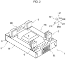
FIG. 2] FIG. 2 is a perspective view showing the support device for a drive battery ofFIG. 1 ; - [
FIG. 3] FIG. 3 is a perspective view showing a state where a drive battery ofFIG. 1 is mounted to a vehicle body; - [
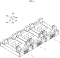
FIG. 4] FIG. 4 is a perspective view showing an example of arrangement when multiple driving batteries according to an embodiment are mounted to the vehicle body; - [
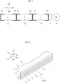
FIG.5] FIG. 5 is a side view schematically showing an example of arrangement of multiple driving batteries and a component when multiple driving batteries are attached to the vehicle body; - [
FIG. 6] FIG. 6 is a perspective view showing a bracket provided to the support device for a drive battery according to the embodiment; - [
FIG. 7] FIG. 7 is a cross-sectional view of the bracket of FIG. 6, (a) showing a normal state (not colliding), (b) showing a state after a collision; - [
FIG. 8] FIG. 8 is a cross-sectional view of a comparative example of the bracket of FIG. 6, (a) showing a normal state (not colliding), (b) showing a state after a collision; - [
FIG. 9] FIG. 9 is a side view schematically showing a modification of arrangement of multiple driving batteries and components when multiple driving batteries are attached to the vehicle body; - [
FIG. 10] FIG. 10 is a perspective vie showing a first modification of the bracket ofFIG. 6 ; - [
FIG. 11] FIG. 11 is a perspective vie showing a second modification of the bracket ofFIG. 6 ; and - [
FIG. 12 ]FIG. 6 is a cross-sectional view showing modifications of the bracket of FIG. 6, (a) showing a third modification, (b) showing the fourth modification. - An embodiment of the present disclosure will now be described with reference to the accompanying drawings. The following example is merely and there is no intention to exclude various modification and application of techniques not explicitly described in the embodiment. Each structure of the following embodiment can be variously modified without departing from the scope thereof, and can be selected or omitted according to requirement, or combined in an appropriate combination.
- As shown in
FIGS. 1-3 , a support device 1 (simply referred to as the support device 1) for a battery pack for a vehicle according to the present embodiment is mounted on anelectric truck 3 havingladder frame 2 forming the skeleton of the vehicle body. Theelectric truck 3 is an electric vehicle that travels by supplying electric power of a drive battery pack (also referred to as "drive battery" and simply "battery pack") 4 to a non-illustrated electric motor. In addition to pure electric vehicles not equipped with an internal combustion engines, electric vehicles also include hybrid vehicles and fuel cell vehicles equipped with driving sources or internal combustion engines for power generation. Further, theelectric truck 3 is also referred to as "electric vehicle 3" or "vehicle 3". - Hereinafter, the front-rear direction of the
electric truck 3 is also referred to as vehicle length direction D1, and the left-right direction of theelectric track 3 is also referred to as vehicle width direction D2. An up-down direction orthogonal to both the front-rear direction and the left-right direction is also referred to as a vehicle height direction D3. In the drawings: front is denoted by "FR"; rear is denoted by "RR"; left hand is denoted by "LH"; right hand is denoted by "RH"; upside is denoted by "UP"; and downside is denoted by "DW". Incidentally,FIG. 4 shows the lower structure of theelectric truck 3 and omits the upper structure (body) disposed on theladder frame 2. - The
ladder frame 2 is a member forming a skeleton of theelectric truck 3, and has high rigidity and high strength. Theladder frame 2 includes a pair ofside rails 21 extending in the vehicle length direction D1, andmultiple cross members 22 extending in the vehicle width direction D2 to connect theside rails 21 to each other. - A pair of
side rails 21 are spaced apart from each other in the vehicle width direction D2. Eachside rail 21 is formed into a channel shape (U-shaped cross section) including a plate-shaped web part 21a along the vehicle length direction D1 and vehicle height direction D3 and a pair of plate-shaped flange parts web part 21a. - The
multiple cross members 22 are spaced apart from one another other in the vehicle length direction D1. Here, twocross members 22 are illustrated, one at an overlapping position with thebattery pack 4 and the other at a position rear to thebattery pack 4. Somebattery pack 4 may include a predetermined component provided in the battery housing (housing) 4A. - To the
battery pack 4, for example, a general-purpose high-voltage battery pack used in a passenger car is applied. In theelectric truck 3, thebattery pack 4 is mounted under the pair of side rails 21 and protrudes outward in the vehicle width direction D2 from the respective side rails 21. Here, a box-shapedbattery pack 4 is illustrated which has a dimension of the vehicle height direction D3 is smaller (thinner) than the respective dimensions of the vehicle length direction D1 and the vehicle width direction D2. However, the shape ofbattery pack 4 is not particularly limited. - The
battery pack 4 has a pair of battery side faces 41, 42, each facing outward of the vehicle width direction D2. The pair of battery side faces 41, 42 are respectively located on the outside in the vehicle width direction D2 of the pair of side rails 21. More specifically, the right battery side face 41 is located to the right side of theright side rail 21, and theleft battery side 42 is located to the left side of theleft side rail 21. - Since the battery side faces 41, 42 of the
battery pack 4 are disposed outside in the vehicle width direction D2 of the side rails 21 as described above, the battery pack reserves the dimension of the vehicle width direction D2 larger than the distance between theweb parts 21a of the side rails 21. This structure allows thebattery pack 4 to have an increased capacity. Thebattery pack 4 is preferably disposed over a wide range between the front wheel axle and the rear wheel axle in order to ensure the cruising range of theelectric truck 3. In anelectric truck 3 having a relatively small size (relatively short wheelbase), asingle battery pack 4 may be disposed over almost the entire wheelbase. In this case, the front wheels are located close to the front of thebattery pack 4, and the rear wheels are located close to the rear of thebattery pack 4. - The size of the
electric truck 3 and the number of the battery packs 4 are not limited to those of the embodiment. In anelectric truck 3 having a relatively large size (relatively long wheelbase),multiple battery packs 4 may be provided side by side in the vehicle length direction D1. Also in this case, by arrangingmultiple battery packs 4 over a wide range of the wheel base, the capacity of the overall entire battery packs 4 is increased, and thereby the cruising range can be ensured. - The
support device 1 couples thebattery pack 4 to the side rails 21 and supports thebattery pack 4. In other words, thebattery pack 4 is supported by the side rails 21 via thesupport device 1. The present embodiment illustrates a support apparatus formed to be symmetric (symmetric about a plane) about a vertical plane passing through the center of the vehicle width direction D2 and extending in the vehicle length direction D1. - As shown in
FIG. 3 side bracket 5 that accommodates thebattery pack 4 and frame-side brackets (coupler bracket) 6 that couples the battery-side bracket 5 and the side rails 21 (seeFIGS. 3 and4 ). The battery-side bracket 5 is an outer wall body disposed on the outer circumference of thebattery pack 4, and has a function of protecting thebattery pack 4 from collision load. On the other hand, the frame-side brackets 6 extend outward in the vehicle width direction D2 and downward from the side rails 21, and have a function of suspending thebattery pack 4 accommodated in the battery-side bracket 5 from the side rails 21. - The battery-
side bracket 5 of the present embodiment has a main bracket (front bracket) 7F disposed so as to cover the front edge part of thebattery pack 4, a main bracket (rear bracket) 7R disposed so as to cover the rear edge part of thebattery pack 4, an end cross member (right bracket) 8R covering the right edge part 40RH of thebattery pack 4, and an end cross member (left bracket) 8L covering the left edge part 40LH of thebattery pack 4. - The pair of
main brackets 7R, 7L have the same shapes as each other, and when they are not distinguished from each other, they are simply referred to themain bracket 7 or abracket 7. The pair ofend cross members - A pair of
main brackets main brackets - The pair of
end cross members 8r, 8L are also formed in longitudinal symmetric to each other with respect to a vertical plane passing through the center of the vehicle length direction D1 and extending in the vehicle width direction D2 as a plane of symmetry. Theend cross members - Each of the
main brackets end cross members side bracket 5 is arranged, with thesemain brackets end cross members 8F, 8R, so as to surround the four sides of thebattery pack 4. - Further, in the present embodiment, as the material of the
main brackets end cross members side bracket 5 and ultimately thesupport device 1 can be lighting while increasing the withstand load strength. Incidentally, the withstand load strength required for thesupport device 1 is strength not damaging the case of thebattery pack 4 even if thesupport device 1 is subjected to certain collision load when the vehicle collides a collision side collision, a front collision, or a rear collision). - However, the material of the battery-
side bracket 5 is not limited to this, and other steel materials or materials except for steel materials may be used. Since further lighting can be achieved if using ultra-high tensile strength steel is defined to have a tensile strength of 1000 MPa or more as steel material having higher tensile strength, but at present, ultra-high tensile strength steel, as compared with the high-tensile strength steel, is difficult to be processed and leads to cost increase, the present embodiment uses high-tensile steel. - Note that definition of high-tensile steel and ultra-high-tensile steel may be different with manufactures, for example. Therefore, the above 490 MPa and 1000 Mpa are exemplarily described as reference values.
- Each of the
main brackets end cross members main brackets 7 each have a web part (side face part) 71, an upper flange part (upper face part) 72, and a lower flange part (lower face part) 73, and the end cross members 8 each have a web part (side face part) 81, a upper flange part (upper face part) 82, and a lower flange part (lower face part) 83. - The
main brackets 7F are arranged so as to cover the front edge part 40FR of thebattery pack 4. That is, themain bracket 7F is arranged in such a posture that theweb part 71 is disposed along thefront face 43 of thebattery pack 4, theupper flange part 72 is disposed along the front side portion of theupper face 45 of thebattery pack 4, and thelower flange part 73 is disposed along the front side portion of thelower face 46 of thebattery pack 4. - The
main bracket 7R is positioned so as to cover the rear edge part 40RR of thebattery pack 4. That is, themain bracket 7R is arranged in such a posture that theweb part 71 is disposed along therear face 44 of thebattery pack 4, theupper flange part 72 is disposed along the rear side portion of theupper face 45 of thebattery pack 4, and thelower flange part 73 is disposed along the rear side portion of thelower face 46 of thebattery pack 4. - The right end-
cross member 8R is arranged so as to cover the right edge part 40RH of thebattery pack 4. That is, theend cross member 8R is arranged in such a posture that theweb part 81 is disposed along theright side surface 41 of thebattery pack 4, theupper flange part 82 is disposed along the right side portion of the upper face45 of thebattery pack 4, thelower flange part 83 is disposed along the right side portion of thelower face 46 of thebattery pack 4. - The left
end cross member 8L is positioned so as to cover the left edge part 40LH of thebattery pack 4. That is, theend cross member 8L is arranged in such a posture that theweb part 81 is disposed along theleft side face 42 of thebattery pack 4, theupper flange part 82 is along the left side portion of theupper face 45 ofbattery pack 4, and thelower flange part 83 is disposed along the left side portion of thelower face 46 of thebattery pack 4. - Further, under a state where the
main brackets 7 are disposed in advance in the front edge part 40FR and the rear edge part 40RR of thebattery pack 4, the end cross members 8 are disposed in the right edge part 40RH and the left edge part 40LH of thebattery pack 4, so that themain brackets 7 and the end cross member 8 are coupled to thebattery pack 4. Accordingly, theflange parts bracket 7 are disposed on the battery pack 4 (inside the vehicle height direction D3) closer than theflange parts - With this configuration, the both ends of the
flange parts main bracket 7 overlap the both ends of theflange parts FIG. 1 ), themain brackets 7 and the end cross members 8 are coupled to each other. InFIG. 1 , one of the overlappingparts 51 is segmented by dot-dot-dashed line. In the present embodiment, themain brackets 7 and the end cross member brackets 8 are coupled by using fasteners such as non-illustrated bolts and multiple fastening holes 90 shown inFIG. 1 . Here, threefastening holes 90 arranged in a triangular shape serve as a set, but the number of holes is not limited to this. Also, the coupling means is not limited to this, and may be coupled by using any fixing device or any bonding means (e.g., welding or gluing). - Further, the end cross member 8 is arranged such that the
web part 81 is spaced apart from with respect to the side faces 41 and 42 of thebattery pack 4, and consequently the deformation allowance (absorb allowance of the collision load) in the event of a collision is reserved. Although this deformation allowance is reserved according to the deformation amount to be assumed, if the deformation allowance is not required, each end cross member 8 can be arranged such that theweb part 81 of end cross member 8 are in contact with the side faces 41, 42 of thebattery pack 4. - As shown in
FIG. 2 , the frame-side brackets 6 are fixed at the lower portions thereof to the upper portion of the overlappingpart 51 in which theupper flanges main bracket 7 and the end cross member 8 overlap and are coupled to each other. Further, each frame-side bracket 6 is, as shown inFIG. 3 fixed to theweb part 21a ofside rail 21. Therefore, the frame-side brackets 6 are provided two for each of the left and right of the electric track 3 (outside the vehicle width direction D2 of the respective side rails 21) (four in total). The portion where theupper flange part 72 of themain bracket 7, theupper flange part 82 of the end cross member 8, and the lower part of the frame-side bracket 6 are coupled is referred to as a coupling part 50 (seeFIG. 1 ). Incidentally, thecoupling part 50 is an contact face of the lower portion of the frame-side bracket 6 with theupper flange part 82 of the end cross member 8, is the entire lower face of the frame-side bracket 6 or the main part of the lower face of the frame-side bracket 6, and is a region located inside of the overlappingpart 51. InFIG. 1 , one of the coupling parts is segmented by dot-dot-dashed line. - Further, as shown in
FIG. 1 , themain bracket 7 and the end cross member 8 are provided with theupper flange parts lower flange parts web parts upper flange parts lower flange parts - Since both ends of the
main bracket 7 and the end cross member 8 havingcoupling parts 50 and overlappingparts 51 require relatively large withstand load strength, both ends of theupper flange part - Furthermore, lightening
holes 84 are formed at the region A in the intermediate part of theupper flange part 82 of the end cross member 8, which region requires relatively small withstand load strength. In this example, the lightening holes 84 are formed by a large number ofsmall holes 84a. Thesmall holes 84a are formed to have the same arrangement and hole diameter asholes 21d for mounting vehicle component provided regularly arranged vertically and horizontally inweb parts 21a of the side rails 21 so that various vehicle components such as on-board devices and tubes, harnesses can be mounted to theholes 84a. - Further, on the intermediate part of the
web part 81 of the end cross member 8, which part requires relatively small withstand load strength, anopening 86 for operation, and lighteningholes 89 are formed. Acover 87 is mounted over theopening 86. Like the holds 21for mounting vehicle components, the lightening holes 89 are formed of a large number ofsmall holes 89a, so thatvehicle components - As described above, the overall capacity of the
battery pack 4 can be increased by arranging the respective units of thebattery pack 4 along the vehicle width direction D1, and consequently, the cruising range can be reserved. For example,FIG. 4 shows an example in which threebattery packs 4 are provided side by side in the vehicle length direction D1.
In this case, as shown inFIG. 5 , themain brackets 7 are disposed on the front and the rear of eachbattery pack 4. - When an attempt is made to efficiently mount the battery packs 4 in a limited space, the respective gaps (clearances) between the
main bracket 7 and thebattery housing 4A and between neighboringmain brackets 7 need to be set as small as possible, and themain brackets 7 are disposed from such a viewpoint. - A vehicle component, which is a component of the
electric vehicle 3, is adapted to be mounted on themain brackets 7 as well as theweb part 21a of theside rail 21 and the end cross members 8. - In the present embodiment, as shown in
FIG. 5 , a fuse box (component) 11 of an electric motor (driving motor) 10 that drives theelectric vehicle 3 is attached to themain bracket 7. - In this example, since the
electric motor 10 is mounted on the rear side of the battery pack 4 (here, rear of a group of the multiple battery packs 4), thefuse box 11 is mounted on themain bracket 7 the closest to theelectric motor 10, that is, themain bracket 7 mounted on the rear edge part 40RR of therearmost battery pack 4. In contrast, as shown inFIG. 9 , when theelectric motor 10 is mounted on the front side of thebattery pack 4, thefuse box 11 is sufficiently attached to themain bracket 7 mounted on the front edge part 40FR of the main bracket 7closest to theelectric motor 10. - The
main bracket 7, as described above, includes aweb part 71, theupper flange part 72, theupper flange part 73. Since it is however difficult to secure an installation space above and under theupper flange part 72 and thelower flange part 73, thefuse box 11 is installed on theweb part 71. For this installation, welding bolts 12 (seeFIG. 7 ) serving as installing member are fixed to theweb part 71. - In order to fix the
welding bolts 12 to theweb part 71, communicating holes are formed on theweb part 71, the shafts of thewelding bolts 12 are inserted into the communicating holes from the inside of the web part 71 (on the side that comes closer to thebattery pack 4 when being installed), and then theheads 12a of thewelding bolts 12 are welded to theweb part 71. - As shown in
FIG. 8(a) , theweb part 71 of themain bracket 7 usually has a flat plate shape, and therefore, in this case, theheads 12a of thewelding bolts 12 protrude from the inner surface of theweb part 71. - When the vehicle undergoes, for example, a front collision or a rear collision, the
battery pack 4 and theweld bolt 12 come close relatively to each other and, as shown inFIG. 8(b) , theheads 12a of thewelding bolts 12 may plunge into thebattery housing 4A, resulting in damages such as perforations in thebattery housing 4A. Since occurrence such damage to thebattery hosing 4A may be a risk, it is desirable to avoid such damage to thebattery housing 4A as much as possible. - Therefore, in the
main bracket 7 of thepresent support device 1, as shown inFIGS. 6 and7(a) , theheads 12a of thewelding bolts 12 is accommodated in thedepressing face parts 13 by formingdepressed face parts 13 which are depressed with respect to the battery pack 4 (battery housing4A) and projectingface parts 14 which are projecting toward the battery pack 4 (thebattery housing 4A) on theweb part 71, forming communicatingholes 15 on the projectingface parts 14, and inserting the shafts of theweld bolts 12 from the inner side of the web part 71 (the side closer to the battery pack 4). - In the present embodiment, the projecting
face parts 14 and thedepressed face part 13 extend linearly (along a straight line), and multiple projectingface parts 14 are provided so as to sandwich the one or moredepressed face parts 13. In the present embodiment, three projectingface part 14 and twodepressed face parts 13 extend horizontally in straight lines. Alternatively, as shown inFIG. 10 , projectingface parts 114 anddepressed face parts 113 with the communicatingholes 115 may linearly extent in the vertical direction. The directions in which the projectingface parts depressed face part face parts depressed face parts - Further, as shown in
FIG. 11 , depressingface parts 213 having communicatingholes 215 and projectingface part 214 may be formed. That is, thedepressed face parts 213 are dispersed in an island-like manner on the projectingface part 214. In this case, the projectingface part 214 are preferably positioned so as to surround the circumferences of thedepressed face parts 213. - In any case, the
tip part 12b of thehead 12a of thewelding bolt 12 accommodated in the indepressed face parts depressed face parts battery housing 4A are arranged at positions further to the sides of the depressed face parts 13,113, 213 than the apex faces 14a of the projectingface parts 14 or the apex faces (not illustrated) of the projectingface parts battery housing 4A or at positions flush with the apex faces. - Further, in any case, in the event of a collision of the
vehicle 3, the apex faces of projecting face parts 14,114,214 are preferably planes parallel to the outer surface of thebattery housing 4A facing these apex faces. With this configuration, if coming close to and colliding with the outer face of the battery hosing 4A, the apex faces 14, 114, 214 are brought into face-to-face contact with thebattery housing 4A. - Further, when multiple projecting
face parts face parts battery housing 4A when the above vehicle collision occurs, it is preferable that the apex faces of the projectingface parts battery housing 4A when the above vehicle collision occurs, it is preferable that the peripheries of projecting face parts 14,114,214 (e.g., the boundary portions between depressed face parts 13,113,213) are not edged. - In the present embodiment, the
battery housing 4A is formed by aluminum die casting, which is relatively light in weight, and as indicated by a shadow pattern in shown inFIG. 7 , has skeleton portions having higher stiffness and strength than the remaining portions. In the present embodiment, the skeleton portions are provided horizontally along the upper part, the lower part, and the intermediate part therebetween of thebattery housing 4A. The skeleton portions can be configured by providing reinforcing members or reinforcing structures for enhancing rigidity and strength. - In the present embodiment, the projecting
face parts - In the present embodiment, the
tip parts 12b of theheads 12a of thewelding bolts 12 are preferably disposed at positions further to the sides of thedepressed face parts face parts tip parts 12b of theheads 12a of thewelding bolts 12 may alternatively be disposed at the positions flush with the apex faces of the projectingface parts battery housing 4A. In this alternative, the overall length of thebattery housing 4A, including thefuse box 11, can be made compact. - Furthermore, in the present embodiment, the apex faces of projecting face parts 14,114,214 are disposed at positions apart from the outer face of the
battery housing 4A, but may alternatively be disposed, as shown inFIG, 12(b) , such that thetip parts 12b of theheads 12a of thewelding bolt 12 are in contact with the outer face of thebattery housing 4A from the beginning.
Also in this alternative, the overall length of thebattery housing 4A, including thefuse box 11, can be made compact. - The
support device 1 for the drive battery according to the present embodiment, which is configured as described above, can obtain the following functions and effects. -
- (1) When the
vehicle 3 collides (a front collision or a rear collision), only theapex face parts battery housing 4A as shown inFIG. 7(b) , or theapex facing parts tip parts 12b of theheads 12a of thewelding bots 12 concurrently collide with thebattery housing 4A. Consequently, it is possible to avoid local collision of the heads of thewelding bolt 12 with thebattery hosing 4A, so that it is possible to inhibit the housing of the battery hosing4A from being damaged. Therefore, the safety is enhanced. - (2) Since the projecting
face parts battery housing 4A has high strength, thebattery housing 4A is less easily damaged even if the projecting face parts 14,114,214 collide with thebattery hosing 4A, so that it is possible to inhibit thebattery housing 4A of the drive battery from being damaged. - (3) Since the projecting
face parts 14 and thedepressed face parts 13 linearly extend and multiple projectingface parts 14 are provided so as to sandwich thedepressed face parts 13, it is possible to surely avoid, when thevehicle 3 collides, a local collision of the heads of thewelding bolt 12 with thebattery housing 4A, so that it is possible to inhibit thebattery housing 4A from being damaged. - (4) By dispersing the
depressed face parts 213 in an island-like manner on the projectingface part 14 and arranging thedepressed face parts 213 so as to surround the circumferences of thedepressed face parts 213, it is possible to surely avoid, when thevehicle 3 collides, a local collision of the heads of thewelding bolt 12 with thebattery housing 4A, so that it is possible to inhibit thebattery housing 4A from being damaged. Be in - (5) By forming the apex faces of the projecting face parts 14,114,214 into flat faces parallel to the outer face of the
battery housing 4A and arranging the projectingface parts battery housing 4A when the projectingface parts battery housing 4A, it is possible to avoid the apex faces of the projectingface parts battery housing 4A, so that it is possible to inhibit the housing of the battery hosing4A from being damaged. - (6)Since the fuse box (component) 11 of the
electric motor 10 that drives theelectric vehicle 3 is attached to themain bracket 7 positioned closer to theelectric motor 10, it is possible to spatial-efficiently arrange thefuse box 11. - The configuration of the above embodiment is exemplary, and can be appropriately changed and implemented without departing from the scope of the present invention.
- For example, in the above embodiment, an example has been described in which the support device for a drive battery is applied to a truck, but the support device for a drive battery of the present embodiment may be applied to a vehicle except for a truck.
- Further, in the above embodiment, the support device for a drive battery is coupled to the side rails 21 and is supported on the side rails 21, the support device may be supported by being coupled to the structural elements of the vehicle except for the side rails 21.
- The shapes of the
depressed face parts face parts - Further, the above embodiment assumes the
fuse box 11 as a component of the electric vehicle, but the configuration of themain bracket 7 of thepresent support device 1 is also applicable to the mounting of other various components. - In the above embodiment, the
weld bolt 12 is exemplified as the installing member, but the installing member is not limited to this. Alternatively, a welding nut or the like may be applied to the installing member. - Further, in the above embodiment, as shown in
FIG. 3 , thedrive battery 4 and thesupport device 1 of the drive battery are arranged to the outer side of the vehicle width direction D2 with respect to side rails 21, but the drive battery and the support device of the drive battery of the present embodiment may be settled between the left and right side rails 21. The size and the shape of the drive battery or its mounting on the side rails or the like can be modified according to the requirement. - In relation to the above embodiment, the following appendices are further disclosed.
- A support device for a drive battery mounted on an electric vehicle, the support device includes:
- a bracket that covers a front side or a rear side of the drive battery and that has a squared C-shaped cross section including a side face part having a depressed face part depressed against the drive battery and a projecting face part projecting toward the drive battery, an upper face part, and a lower face part; and
- an installing member that installs a component of the electric vehicle, wherein
- the installing member is attached to the depressed face part, and
- a tip part of the installing member projecting from the depressed face part to the drive battery is arranged at a position departing from an outer face of a housing of the drive battery further to the depressed face part than an apex face of the projecting face part or at a position flush with the apex face.
- The support device for a drive battery according to
appendix 1, wherein
the projecting face part is arranged at a position facing a portion of the housing, the portion having high strength. - The support device for a drive battery according to
appendix - the projecting face part and the depressed face part linearly extend; and
- a plurality of the projecting face parts are provided so as to sandwich the depressed face part.
- The support device for a drive battery according to
appendix
the projecting face part extends around a circumference of the depressed face part. - The support device for a drive battery according to any one of
appendices 1 to 4, wherein
the projecting face part is arranged such that the apex face is in contact with a face of the housing. - The support device for a drive battery according to any one of
appendices 1 to 5, wherein
the component is a fuse box of a driving motor of the electric vehicle. -
- 1
- support device (support device for drive battery)
- 2
- ladder frame
- 3
- electric truck (electric vehicle, vehicle)
- 4
- battery pack for driving (drive battery, battery pack)
- 4A
- battery housing
- 5
- battery-side bracket
- 6
- frame-side bracket (coupler bracket)
- 7F, 7
- main bracket (front bracket)
- 7R, 7
- main bracket (rear bracket)
- 8R, 8
- end cross member (right bracket)
- 8L, 8
- end cross member (left bracket)
- 10
- electric motor (driving motor)
- 11
- fuse box (component)
- 12
- welding bot (installing member)
- 12a
- head of
welding bolt 12 - 12b
- tip part of
head 12a ofwelding bolt 12 - 13, 113, 213
- depressed face part
- 14, 114, 214
- projecting face part
- 14a
- apex face of projecting
face part 14 - 15, 115, 215
- communicating hole
- 21
- side rail
- 21a
- web part of
side rail 21 - 21b, 21c
- flange part of
side rail 21 - 21d
- hole for mounting vehicle component
- 22
- cross member
- 40FR
- front edge part of
battery pack 4 - 40RR
- rear edge part of
battery pack 4 - 40RH
- right edge part of
battery pack 4 - 40LH
- left edge part of
battery pack 4 - 41
- right side face of
battery 4 - 42
- left side face of
battery 4 - 43
- front face of
battery pack 4 - 44
- rear face of
battery pack 4 - 45
- upper face of
battery pack 4 - 46
- lower face of
battery pack 4 - 50
- coupling part
- 51
- overlapping part
- 71
- web part (side face part) of
main bracket 7 - 72
- upper flange part (upper face part) of
main bracket 7 - 73
- lower flange part (lower face part) of
main bracket 7 - 81
- web part (side face part) of end cross member 8
- 82
- upper flange part (upper face part)
- 83
- lower flange part (lower face part)
- 84
- lightening hole
- 84a
- small hole as lightening
hole 84 - 85
- lightening hole
- 86
- opening
- 87
- cover
- 89
- lightening hole
- 89a
- small hole as lightening
hole 89 - 90
- fastening hole
- 91
- communicating hole
- 92, 93, 94
- vehicle component
- D1
- vehicle length direction D1
- D2
- vehicle width direction D2
- D3
- vehicle height direction D3
- L1, L2
- boundary line
- FR
- front
- RR
- rear
- LH
- left hand
- RH
- right hand
- UP
- upside
- DW
- downside
- P
- protruding amount from
web part flange part
Claims (6)
- A support device for a drive battery mounted on an electric vehicle, the support device comprising:a bracket that covers a front side or a rear side of the drive battery and that has a squared C-shaped cross section comprising a side face part having a depressed face part depressed against the drive battery and a projecting face part projecting toward the drive battery, an upper face part, and a lower face part; andan installing member that installs a component of the electric vehicle, whereinthe installing member is attached to the depressed face part, anda tip part of the installing member projecting from the depressed face part to the drive battery is arranged at a position departing from an outer face of a housing of the drive battery further to the depressed face part than an apex face of the projecting face part or at a position flush with the apex face.
- The support device for a drive battery according to claim 1, wherein
the projecting face part is arranged at a position facing a portion of the housing, the portion having high strength. - The support device for a drive battery according to claim 1, whereinthe projecting face part and the depressed face part linearly extend; anda plurality of the projecting face parts are provided so as to sandwich the depressed face part.
- The support device for a drive battery according to claim 1, wherein
the projecting face part extends around a circumference of the depressed face part. - The support device for a drive battery according to claim 1, wherein the projecting face part is arranged such that the apex face is in contact with a face of the housing.
- The support device for a drive battery according to any one of claims 1-5, wherein
the component is a fuse box of a driving motor of the electric vehicle.
Applications Claiming Priority (2)
| Application Number | Priority Date | Filing Date | Title |
|---|---|---|---|
| JP2022085909A JP7804534B2 (en) | 2022-05-26 | 2022-05-26 | Drive battery support device |
| PCT/JP2023/015953 WO2023228656A1 (en) | 2022-05-26 | 2023-04-21 | Support device for drive battery |
Publications (2)
| Publication Number | Publication Date |
|---|---|
| EP4516547A1 true EP4516547A1 (en) | 2025-03-05 |
| EP4516547A4 EP4516547A4 (en) | 2025-07-16 |
Family
ID=88918947
Family Applications (1)
| Application Number | Title | Priority Date | Filing Date |
|---|---|---|---|
| EP23811534.9A Pending EP4516547A4 (en) | 2022-05-26 | 2023-04-21 | Support device for a drive battery |
Country Status (5)
| Country | Link |
|---|---|
| US (1) | US20250360808A1 (en) |
| EP (1) | EP4516547A4 (en) |
| JP (1) | JP7804534B2 (en) |
| CN (1) | CN119278138A (en) |
| WO (1) | WO2023228656A1 (en) |
Family Cites Families (8)
| Publication number | Priority date | Publication date | Assignee | Title |
|---|---|---|---|---|
| JPH07108886A (en) * | 1993-10-13 | 1995-04-25 | Toyota Motor Corp | Car bumper cover |
| JP6367066B2 (en) * | 2014-06-10 | 2018-08-01 | 立川ブラインド工業株式会社 | Guide rail |
| JP2016113063A (en) | 2014-12-16 | 2016-06-23 | ダイムラー・アクチェンゲゼルシャフトDaimler AG | Battery box-holding structure |
| CA3110459C (en) * | 2018-08-24 | 2024-06-18 | Hexagon Purus North America Holdings Inc. | Battery system for heavy duty vehicles |
| JP7413739B2 (en) * | 2019-11-29 | 2024-01-16 | メルセデス・ベンツ グループ アクチェンゲゼルシャフト | Vehicle battery pack support device |
| DE102019133496B3 (en) * | 2019-12-09 | 2020-12-17 | Dr. Ing. H.C. F. Porsche Aktiengesellschaft | Partial body for an at least partially electrically operated motor vehicle and motor vehicle |
| JP7205778B2 (en) * | 2020-09-30 | 2023-01-17 | いすゞ自動車株式会社 | Vehicle battery support structure |
| JP7525365B2 (en) * | 2020-10-09 | 2024-07-30 | ダイムラー トラック エージー | Battery pack support device and electric truck |
-
2022
- 2022-05-26 JP JP2022085909A patent/JP7804534B2/en active Active
-
2023
- 2023-04-21 EP EP23811534.9A patent/EP4516547A4/en active Pending
- 2023-04-21 WO PCT/JP2023/015953 patent/WO2023228656A1/en not_active Ceased
- 2023-04-21 US US18/868,041 patent/US20250360808A1/en active Pending
- 2023-04-21 CN CN202380042589.9A patent/CN119278138A/en active Pending
Also Published As
| Publication number | Publication date |
|---|---|
| US20250360808A1 (en) | 2025-11-27 |
| JP7804534B2 (en) | 2026-01-22 |
| CN119278138A (en) | 2025-01-07 |
| WO2023228656A1 (en) | 2023-11-30 |
| EP4516547A4 (en) | 2025-07-16 |
| JP2023173571A (en) | 2023-12-07 |
Similar Documents
| Publication | Publication Date | Title |
|---|---|---|
| CN114206685B (en) | Bumper beam for a vehicle | |
| US12337673B2 (en) | Support apparatus for battery pack and electric truck | |
| EP4344982A1 (en) | Support device for vehicular battery pack and electric truck | |
| EP4056456A1 (en) | Support device for vehicle battery pack and electric vehicle | |
| US20140014794A1 (en) | Onboard equipment fixing structure | |
| US20180229772A1 (en) | Vehicle | |
| JP7769512B2 (en) | Battery module protection structure | |
| CN117429515A (en) | Protective structures for underfloor components | |
| EP4516547A1 (en) | Support device for drive battery | |
| JP7714389B2 (en) | Support device for vehicle battery pack | |
| JP2024007745A (en) | fuel cell car | |
| CN119840402A (en) | Battery pack and vehicle body sealing structure, vehicle body and vehicle | |
| EP4516546A1 (en) | Supporting device for driving battery | |
| JP7322914B2 (en) | In-vehicle equipment mounting device | |
| CN116507517A (en) | electric truck | |
| JP2025037535A (en) | Support device for drive battery | |
| CN113246711B (en) | Battery package mounting structure and back floor assembly | |
| JP2024165517A (en) | Device for preventing drive battery from falling off | |
| CN220298283U (en) | vehicle | |
| JP2023006070A (en) | Support device for vehicle battery pack | |
| JP2025021687A (en) | Drive battery mounting structure | |
| JP2022085063A (en) | Battery pack support device | |
| JP2024030194A (en) | battery support device | |
| KR20250051849A (en) | Battery protection structure of the car body | |
| JP2023006071A (en) | Support device for vehicle battery pack |
Legal Events
| Date | Code | Title | Description |
|---|---|---|---|
| STAA | Information on the status of an ep patent application or granted ep patent |
Free format text: STATUS: THE INTERNATIONAL PUBLICATION HAS BEEN MADE |
|
| PUAI | Public reference made under article 153(3) epc to a published international application that has entered the european phase |
Free format text: ORIGINAL CODE: 0009012 |
|
| STAA | Information on the status of an ep patent application or granted ep patent |
Free format text: STATUS: REQUEST FOR EXAMINATION WAS MADE |
|
| 17P | Request for examination filed |
Effective date: 20241126 |
|
| AK | Designated contracting states |
Kind code of ref document: A1 Designated state(s): AL AT BE BG CH CY CZ DE DK EE ES FI FR GB GR HR HU IE IS IT LI LT LU LV MC ME MK MT NL NO PL PT RO RS SE SI SK SM TR |
|
| A4 | Supplementary search report drawn up and despatched |
Effective date: 20250613 |
|
| RIC1 | Information provided on ipc code assigned before grant |
Ipc: B60K 1/04 20190101AFI20250606BHEP Ipc: B62D 21/02 20060101ALI20250606BHEP |
|
| DAV | Request for validation of the european patent (deleted) | ||
| DAX | Request for extension of the european patent (deleted) |