EP4516532A2 - Two piece wheel - Google Patents
Two piece wheel Download PDFInfo
- Publication number
- EP4516532A2 EP4516532A2 EP25151579.7A EP25151579A EP4516532A2 EP 4516532 A2 EP4516532 A2 EP 4516532A2 EP 25151579 A EP25151579 A EP 25151579A EP 4516532 A2 EP4516532 A2 EP 4516532A2
- Authority
- EP
- European Patent Office
- Prior art keywords
- wheel
- section
- spoke
- barrel section
- mating surface
- Prior art date
- Legal status (The legal status is an assumption and is not a legal conclusion. Google has not performed a legal analysis and makes no representation as to the accuracy of the status listed.)
- Pending
Links
Images



Classifications
-
- B—PERFORMING OPERATIONS; TRANSPORTING
- B60—VEHICLES IN GENERAL
- B60B—VEHICLE WHEELS; CASTORS; AXLES FOR WHEELS OR CASTORS; INCREASING WHEEL ADHESION
- B60B25/00—Rims built-up of several main parts ; Locking means for the rim parts
- B60B25/04—Rims with dismountable flange rings, seat rings, or lock rings
- B60B25/10—Seat rings for the tyre bead part, e.g. split
- B60B25/12—Seat rings for the tyre bead part, e.g. split with integral flange part
-
- B—PERFORMING OPERATIONS; TRANSPORTING
- B60—VEHICLES IN GENERAL
- B60B—VEHICLE WHEELS; CASTORS; AXLES FOR WHEELS OR CASTORS; INCREASING WHEEL ADHESION
- B60B25/00—Rims built-up of several main parts ; Locking means for the rim parts
- B60B25/002—Rims split in circumferential direction
- B60B25/004—Rims split in circumferential direction one rim part comprising the wheel disc
-
- B—PERFORMING OPERATIONS; TRANSPORTING
- B60—VEHICLES IN GENERAL
- B60B—VEHICLE WHEELS; CASTORS; AXLES FOR WHEELS OR CASTORS; INCREASING WHEEL ADHESION
- B60B25/00—Rims built-up of several main parts ; Locking means for the rim parts
- B60B25/22—Other apurtenances, e.g. for sealing the component parts enabling the use of tubeless tyres
-
- B—PERFORMING OPERATIONS; TRANSPORTING
- B60—VEHICLES IN GENERAL
- B60B—VEHICLE WHEELS; CASTORS; AXLES FOR WHEELS OR CASTORS; INCREASING WHEEL ADHESION
- B60B3/00—Disc wheels, i.e. wheels with load-supporting disc body
- B60B3/04—Disc wheels, i.e. wheels with load-supporting disc body with a single disc body not integral with rim, i.e. disc body and rim being manufactured independently and then permanently attached to each other in a second step, e.g. by welding
- B60B3/041—Disc wheels, i.e. wheels with load-supporting disc body with a single disc body not integral with rim, i.e. disc body and rim being manufactured independently and then permanently attached to each other in a second step, e.g. by welding characterised by the attachment of rim to wheel disc
-
- B—PERFORMING OPERATIONS; TRANSPORTING
- B60—VEHICLES IN GENERAL
- B60B—VEHICLE WHEELS; CASTORS; AXLES FOR WHEELS OR CASTORS; INCREASING WHEEL ADHESION
- B60B5/00—Wheels, spokes, disc bodies, rims, hubs, wholly or predominantly made of non-metallic material
- B60B5/02—Wheels, spokes, disc bodies, rims, hubs, wholly or predominantly made of non-metallic material made of synthetic material
-
- B—PERFORMING OPERATIONS; TRANSPORTING
- B60—VEHICLES IN GENERAL
- B60B—VEHICLE WHEELS; CASTORS; AXLES FOR WHEELS OR CASTORS; INCREASING WHEEL ADHESION
- B60B2310/00—Manufacturing methods
- B60B2310/30—Manufacturing methods joining
- B60B2310/318—Manufacturing methods joining by adhesive bonding, e.g. glueing
-
- B—PERFORMING OPERATIONS; TRANSPORTING
- B60—VEHICLES IN GENERAL
- B60B—VEHICLE WHEELS; CASTORS; AXLES FOR WHEELS OR CASTORS; INCREASING WHEEL ADHESION
- B60B2360/00—Materials; Physical forms thereof
- B60B2360/10—Metallic materials
-
- B—PERFORMING OPERATIONS; TRANSPORTING
- B60—VEHICLES IN GENERAL
- B60B—VEHICLE WHEELS; CASTORS; AXLES FOR WHEELS OR CASTORS; INCREASING WHEEL ADHESION
- B60B2360/00—Materials; Physical forms thereof
- B60B2360/10—Metallic materials
- B60B2360/102—Steel
-
- B—PERFORMING OPERATIONS; TRANSPORTING
- B60—VEHICLES IN GENERAL
- B60B—VEHICLE WHEELS; CASTORS; AXLES FOR WHEELS OR CASTORS; INCREASING WHEEL ADHESION
- B60B2360/00—Materials; Physical forms thereof
- B60B2360/10—Metallic materials
- B60B2360/104—Aluminum
-
- B—PERFORMING OPERATIONS; TRANSPORTING
- B60—VEHICLES IN GENERAL
- B60B—VEHICLE WHEELS; CASTORS; AXLES FOR WHEELS OR CASTORS; INCREASING WHEEL ADHESION
- B60B2360/00—Materials; Physical forms thereof
- B60B2360/30—Synthetic materials
- B60B2360/34—Reinforced plastics
-
- B—PERFORMING OPERATIONS; TRANSPORTING
- B60—VEHICLES IN GENERAL
- B60B—VEHICLE WHEELS; CASTORS; AXLES FOR WHEELS OR CASTORS; INCREASING WHEEL ADHESION
- B60B2360/00—Materials; Physical forms thereof
- B60B2360/30—Synthetic materials
- B60B2360/34—Reinforced plastics
- B60B2360/341—Reinforced plastics with fibres
- B60B2360/3412—Glass fibres
-
- B—PERFORMING OPERATIONS; TRANSPORTING
- B60—VEHICLES IN GENERAL
- B60B—VEHICLE WHEELS; CASTORS; AXLES FOR WHEELS OR CASTORS; INCREASING WHEEL ADHESION
- B60B2360/00—Materials; Physical forms thereof
- B60B2360/30—Synthetic materials
- B60B2360/34—Reinforced plastics
- B60B2360/341—Reinforced plastics with fibres
- B60B2360/3416—Carbone fibres
-
- B—PERFORMING OPERATIONS; TRANSPORTING
- B60—VEHICLES IN GENERAL
- B60B—VEHICLE WHEELS; CASTORS; AXLES FOR WHEELS OR CASTORS; INCREASING WHEEL ADHESION
- B60B2360/00—Materials; Physical forms thereof
- B60B2360/30—Synthetic materials
- B60B2360/34—Reinforced plastics
- B60B2360/348—Resins
-
- B—PERFORMING OPERATIONS; TRANSPORTING
- B60—VEHICLES IN GENERAL
- B60B—VEHICLE WHEELS; CASTORS; AXLES FOR WHEELS OR CASTORS; INCREASING WHEEL ADHESION
- B60B3/00—Disc wheels, i.e. wheels with load-supporting disc body
- B60B3/06—Disc wheels, i.e. wheels with load-supporting disc body formed by casting
-
- Y—GENERAL TAGGING OF NEW TECHNOLOGICAL DEVELOPMENTS; GENERAL TAGGING OF CROSS-SECTIONAL TECHNOLOGIES SPANNING OVER SEVERAL SECTIONS OF THE IPC; TECHNICAL SUBJECTS COVERED BY FORMER USPC CROSS-REFERENCE ART COLLECTIONS [XRACs] AND DIGESTS
- Y02—TECHNOLOGIES OR APPLICATIONS FOR MITIGATION OR ADAPTATION AGAINST CLIMATE CHANGE
- Y02T—CLIMATE CHANGE MITIGATION TECHNOLOGIES RELATED TO TRANSPORTATION
- Y02T10/00—Road transport of goods or passengers
- Y02T10/80—Technologies aiming to reduce greenhouse gasses emissions common to all road transportation technologies
- Y02T10/86—Optimisation of rolling resistance, e.g. weight reduction
Definitions
- the present disclosure relates to wheels for automobiles and other wheeled vehicles.
- the present disclosure relates to a two (2) piece wheel.
- the present disclosure provides a novel and unique two (2) piece molded wheel that offers many benefits including reduced weight, varied appearance, reduced cost and increased fuel economy. More specifically, the present disclosure provides a wheel that minimizes the weight thereof but retains the necessary strength.
- the composite wheels in the prior art are often extremely expensive due to the costs of materials involved in the manufacture thereof and the time involved to manufacture each wheel.
- the present disclosure provides a strong, attractive and light weight two (2) piece wheel that is cheaper and easy to manufacture.
- the present disclosure provides a two (2) piece molded wheel comprising a spoke section and a barrel section, wherein the spoke section and barrel sections are joined at the drop center of the wheel.
- the present disclosure provides a two (2) piece wheel comprising a first section and a second section wherein the wheel comprises areas of varying diameter across its width and the first section and second section are joined at the area of the wheel with the smallest diameter.
- the present application provides an improved, two (2) piece wheel 10 which may be used on various automobiles, including but not limited to passenger cars and trucks.
- the wheel 10 disclosed herein offers many advantageous features not found in prior art wheels such as a lighter weight and stronger construction.
- Fig. 1 shows a front view of the wheel 10 fully assembled.
- the wheel comprises a spoke section 20 (which is furthest away from the automobile on which the wheel 10 is installed) and a barrel section 30 (which is closer to the automobile on which the wheel is installed).
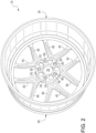
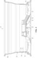
- Fig. 2 shows a rear view of the wheel fully assembled while Fig. 3 shows a top sectional view of the fully assembled wheel 10.
- the spoke section 20 includes one or more spokes 40 that both serve to add strength to the wheel 10 and also provide a pleasing decorative appearance.
- spokes 40 that both serve to add strength to the wheel 10 and also provide a pleasing decorative appearance.
- the spokes section 20 and spokes 40 may also include one or more fiber composite strips 25.
- the fiber composite strips 25 can be either co-molded between fiber layers as the spoke section 20/spokes 40 are molded or they may be bonded to the spoke section 20/spokes 40 after those features are molded.
- the fiber composite strips 25, as shown in Fig. 3 may be placed along the exterior surface of one or more spokes 40 or alternatively, they may be located where the spokes 40 meet the hub or center of the spoke section, along the lip or outer edge of the spoke section or where the spokes 40 meet the barrel.
- the spoke section 20 also includes a plurality of apertures near its center, including one or more wheel stud apertures 50 and a hub aperture 70.
- the wheel stud apertures 50 are configured to receive the threaded wheel studs (or sometimes called wheel bolts) present on the hub of the vehicle on which the wheel 10 will be installed. Accordingly, as shown in the attached figures, there may be five (5) wheel stud apertures (which is the common number on most passenger cars) but there could be more or less wheel stud apertures if needed for installation on a particular vehicle or vehicle type. For example, there could be as few as four (4) wheel stud apertures or as many as twelve (12).
- the spoke section 20 may include one or more inserts 55 that can be generally complimentary to the shape and size of the wheel stud apertures 50.
- These inserts 55 may be molded integrally near the region of the spoke section 20 proximate to the wheel stud apertures 50.
- These inserts 55 can be of various shapes and composition.
- the insert 55 may complement the shape and size of the wheel stud aperture 50 and form a concentric circle therewith, as shown in Fig. 2 and be placed around one or more of the wheel stud apertures 50.
- the insert 55 could be rectangular and placed proximate to the wheel stud aperture, but not of a circular shape.
- the insert 55 may be metal or other suitable materials to help distribute the forces imparted on the wheel 10 when the lug nuts are tightened onto the wheel studs.
- the hub aperture 70 is provided such that the hub of a vehicle may pass through the spoke section 20.
- the dimensions of the hub aperture 70 will often vary due to the make and model of vehicle on which the wheel 10 is to be installed - i.e., a wheel designed to be installed on a Ford ® may have a different dimensioned hub aperture 70 than a wheel designed to fit on a Subaru ® .
- the spoke section 20 also includes a valve stem aperture 60 which receives a valve stem which is used to add air (or other suitable gasses such as nitrogen) to the tire seated on the wheel 10.
- the spoke section 20 also includes a beadhump 100 on its interior facing surface that secures the bead of the tire to the wheel 10.
- the spoke section 20 also has a mating surface 80 which is in contact with the barrel surface's mating surface 110 when the wheel 10 is assembled (as discussed in more detail below).
- the barrel section 30 is the portion of the wheel 10 closest to the automobile.
- the barrel section 30 reduces in diameter across its width, or put another way, the inner most portion of the barrel section 30 may have a larger diameter than the outermost portion.
- the barrel section 30 has a mating surface 110 that may be complementary to the spoke section's mating surface 80.
- different areas of the wheel 10 have different diameters.
- the area of the wheel with the bead hump 100 has a different diameter than the central area of the wheel 10.
- the mating surface 110 is generally located at the drop center (also known as the tire well) of the wheel 10, or the area of the wheel where it is the narrowest, and thus the opposing mating surface 80 of the spoke section 20 where the sections are joined is also located at the drop center, and the drop center of a wheel 10 makes mounting a tire easier in that it allows the tire's bead wires to retain their natural shape/length/diameter during the mounting process.
- the bead hump 100 may be molded or formed integrally with the spoke section 20 and barrel section 30, as shown in Fig. 5 or it may be manufactured separately and affixed or attached to the spoke section 20 and barrel section 30 as shown in Fig. 6 .
- the mating surface 110 of the barrel section 30 includes one or more spacers 120 which serve to provide a gap between the spoke sections 20 mating surface 80 and the barrel section's mating surface 110 after the wheel is assembled. This gap allows space for the adhesive used to join the spoke section 20 and the barrel section 30 to be applied evenly and to properly harden and attach the two sections thus creating a strong, reliable wheel 10.
- the adhesive can be selected from the group consisting of urethane and epoxy based adhesives.
- the spacers 130 have a height of between 5 and 60 one-thousandth's of an inch.
- the mating surface 80 of the spoke section may comprise the one or more spacers rather than the barrel section 30.
- the mating surface 110 of the barrel section 30 may have a lip or stop 130 that the leading edge of the spoke section's mating surface 80 rests against once the two sections are fitted properly during assembly.
- This lip or stop 130 serves to provide that adequate overlap is created by the two opposing mating surfaces 80, 110 to provide for a secure assembly.
- the amount of overlap may vary depending upon the desired use of the wheel. In some embodiments, the amount of overlap is between 0.10 and 6.00 inches, 0.50 and 5.00 inches, 1.00 and 4.0 inches and 1.50 and 3.0 inches. In one preferred embodiment, the amount of overlap is between 1.50 and 2.00 inches.
- the overlap region could feature a tongue-and-groove construction or threads to assist in securing the spoke section 20 to the barrel section 30.
- mechanical securement devices such as rivets, bolts or a tape may be used.
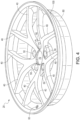
- Figs. 4 and 5 show perspective views of the spoke section 20 and the barrel section 30 respectively.
- Fig. 6 shows a side view/cut away view of the overlap of the opposing mating surfaces 80, 110.
- the wheel 10 may be made of many different materials, including composite materials such as carbon fiber.
- carbon fiber as used herein includes all fibers which consist essentially of carbon, ranging from graphite fibers to amorphous carbon fibers.
- Graphite fibers are fibers which consist essentially of carbon and have a predominant X-ray diffraction pattern characteristic of graphite.
- Amorphous carbon fibers are fibers which consist essentially of carbon and have an essentially amorphous X-ray diffraction pattern.
- the term also includes other high strength, low density materials such as boron, fiber glass or the like or any of the forgoing in a mixture, such as 1-99 % carbon fiber mixed with 99-1% fiber glass.
- the wheel 10 may comprise one or more of the following composite materials a carbon fiber/fiber mixture, carbon fiber or fiber glass. Additionally, additives such as nanoparticles may be added to the composite materials before molding. Additionally, the wheel 10 disclosed herein may not be manufactured from a composite material but rather a metallic material such as aluminum, steel or other alloy. In an embodiment where the wheel 10 is manufactured from a metallic material, the components of the wheel may be forged, cast or machined.
- a resin is used to bind the composite materials during molding.
- the resin is selected from the group consisting of epoxies, polyurethane, rubber and polyester resins.
- the resin is a vinyl ester/polyurethane resin or any other thermoset or thermoplastic polymeric resin or a metallic matrix.
- the resin may be selected from the group consisting of butadiene rubber, ethylene-propylene-diene rubber, melamine formaldehyde, natural rubber, phenolformaldehyde, polyamide, polycarbonate, polypropylene and polytetrafluoroethylene.
- the wheel 10 may be constructed using various methods of manufacture including compression molding.
- the wheel 10 is constructed using a sheet molding compound (SMC) process or a bulk molding compound (BMC) process.
- SMC sheet molding compound
- BMC bulk molding compound
Landscapes
- Engineering & Computer Science (AREA)
- Mechanical Engineering (AREA)
- Chemical & Material Sciences (AREA)
- Materials Engineering (AREA)
- Connection Of Plates (AREA)
- Braking Arrangements (AREA)
- Pens And Brushes (AREA)
- Looms (AREA)
- Tires In General (AREA)
- Vehicle Step Arrangements And Article Storage (AREA)
- Arrangements For Transmission Of Measured Signals (AREA)
- Spectrometry And Color Measurement (AREA)
- Molds, Cores, And Manufacturing Methods Thereof (AREA)
- Body Structure For Vehicles (AREA)
Abstract
Description
- This application claims priority to, and the benefit of, pending
U.S. Provisional Patent Application No. 62/542,520 filed on August 8, 2017 - The present disclosure relates to wheels for automobiles and other wheeled vehicles. In particular, the present disclosure relates to a two (2) piece wheel.
- As is well known, consumers often want multiple choices and options when purchasing an automobile to allow them options based on look, price or some other trait (such as fuel economy). With this in mind, the present disclosure provides a novel and unique two (2) piece molded wheel that offers many benefits including reduced weight, varied appearance, reduced cost and increased fuel economy. More specifically, the present disclosure provides a wheel that minimizes the weight thereof but retains the necessary strength.
- The composite wheels in the prior art are often extremely expensive due to the costs of materials involved in the manufacture thereof and the time involved to manufacture each wheel. The present disclosure provides a strong, attractive and light weight two (2) piece wheel that is cheaper and easy to manufacture.
- In one aspect, the present disclosure provides a two (2) piece molded wheel comprising a spoke section and a barrel section, wherein the spoke section and barrel sections are joined at the drop center of the wheel.
- In another aspect, the present disclosure provides a two (2) piece wheel comprising a first section and a second section wherein the wheel comprises areas of varying diameter across its width and the first section and second section are joined at the area of the wheel with the smallest diameter.
- To further illustrate the advantages and features of the present disclosure, a more particular description of the invention will be rendered by reference to specific embodiments thereof which are illustrated in the attached drawings. It is appreciated that these drawings are not to be considered limiting in scope. The invention will be described and explained with additional specificity and detail through the use of the drawings in which:
-
Fig. 1 shows a front view of one embodiment of the wheel of the present disclosure. -
Fig. 2 shows a rear view of one embodiment of the wheel of the present disclosure. -
Fig. 3 shows a top sectional view of one embodiment of the wheel of the present disclosure. -
Fig. 4 shows a perspective view of one embodiment of the spoke section of the present disclosure. -
Fig. 5 shows a perspective view of one embodiment of the barrel section of the present disclosure. -
Fig. 6 shows a side view of the joining of the barrel section and spoke section. - As shown in
Figs. 1-6 , the present application provides an improved, two (2)piece wheel 10 which may be used on various automobiles, including but not limited to passenger cars and trucks. Thewheel 10 disclosed herein offers many advantageous features not found in prior art wheels such as a lighter weight and stronger construction. -
Fig. 1 shows a front view of thewheel 10 fully assembled. The wheel comprises a spoke section 20 (which is furthest away from the automobile on which thewheel 10 is installed) and a barrel section 30 (which is closer to the automobile on which the wheel is installed).Fig. 2 shows a rear view of the wheel fully assembled whileFig. 3 shows a top sectional view of the fully assembledwheel 10. - The
spoke section 20 includes one ormore spokes 40 that both serve to add strength to thewheel 10 and also provide a pleasing decorative appearance. As such, one of ordinary skill in the art can appreciate that although one design is shown in the figures included herewith, many different spoke designs and arrangements are possible based on consumer preference and the scope of the present invention should not be limited by the design shown in the figures. Additionally, the shape, design, number and length of thespokes 40 can be varied to increase the strength of thewheel 10. Thespokes section 20 andspokes 40 may also include one or morefiber composite strips 25. Thefiber composite strips 25 can be either co-molded between fiber layers as thespoke section 20/spokes 40 are molded or they may be bonded to thespoke section 20/spokes 40 after those features are molded. Thefiber composite strips 25, as shown inFig. 3 , may be placed along the exterior surface of one ormore spokes 40 or alternatively, they may be located where thespokes 40 meet the hub or center of the spoke section, along the lip or outer edge of the spoke section or where thespokes 40 meet the barrel. - The
spoke section 20 also includes a plurality of apertures near its center, including one or morewheel stud apertures 50 and ahub aperture 70. Thewheel stud apertures 50 are configured to receive the threaded wheel studs (or sometimes called wheel bolts) present on the hub of the vehicle on which thewheel 10 will be installed. Accordingly, as shown in the attached figures, there may be five (5) wheel stud apertures (which is the common number on most passenger cars) but there could be more or less wheel stud apertures if needed for installation on a particular vehicle or vehicle type. For example, there could be as few as four (4) wheel stud apertures or as many as twelve (12). As shown in the attached figures, there may be a recess on the exterior of thespoke section 20 in which the lug nuts fit during installation, though this is not required. Alternatively, there may only be a single aperture on the wheel wherein the hub passes through the aperture and a nut is threaded onto the hub to secure to the wheel. - Optionally, the
spoke section 20 may include one ormore inserts 55 that can be generally complimentary to the shape and size of thewheel stud apertures 50. Theseinserts 55 may be molded integrally near the region of thespoke section 20 proximate to thewheel stud apertures 50. Theseinserts 55 can be of various shapes and composition. For example, theinsert 55 may complement the shape and size of thewheel stud aperture 50 and form a concentric circle therewith, as shown inFig. 2 and be placed around one or more of thewheel stud apertures 50. Alternatively, theinsert 55 could be rectangular and placed proximate to the wheel stud aperture, but not of a circular shape. Theinsert 55 may be metal or other suitable materials to help distribute the forces imparted on thewheel 10 when the lug nuts are tightened onto the wheel studs. After the wheel studs are passed through thewheel stud apertures 50, generally one or more lug nuts or other securement device will be screwed onto the threaded wheel studs to attach thewheel 10 securely to the vehicle. Thehub aperture 70 is provided such that the hub of a vehicle may pass through thespoke section 20. As one of ordinary skill in the art can appreciate, the dimensions of thehub aperture 70 will often vary due to the make and model of vehicle on which thewheel 10 is to be installed - i.e., a wheel designed to be installed on a Ford® may have a differentdimensioned hub aperture 70 than a wheel designed to fit on a Subaru®. - The
spoke section 20 also includes avalve stem aperture 60 which receives a valve stem which is used to add air (or other suitable gasses such as nitrogen) to the tire seated on thewheel 10. - The
spoke section 20 also includes abeadhump 100 on its interior facing surface that secures the bead of the tire to thewheel 10. - The
spoke section 20 also has amating surface 80 which is in contact with the barrel surface'smating surface 110 when thewheel 10 is assembled (as discussed in more detail below). - The
barrel section 30 is the portion of thewheel 10 closest to the automobile. Thebarrel section 30, like thespoke section 20, includes abeadhump 100 on its exterior facing surface that secures the bead of the tire to thewheel 10. In one embodiment, as shown inFig. 5 for example, thebarrel section 30 reduces in diameter across its width, or put another way, the inner most portion of thebarrel section 30 may have a larger diameter than the outermost portion. - Further, the
barrel section 30 has amating surface 110 that may be complementary to the spoke section'smating surface 80. As can be appreciated from the attached drawings, different areas of thewheel 10 have different diameters. For example, the area of the wheel with thebead hump 100 has a different diameter than the central area of thewheel 10. In one embodiment themating surface 110 is generally located at the drop center (also known as the tire well) of thewheel 10, or the area of the wheel where it is the narrowest, and thus theopposing mating surface 80 of thespoke section 20 where the sections are joined is also located at the drop center, and the drop center of awheel 10 makes mounting a tire easier in that it allows the tire's bead wires to retain their natural shape/length/diameter during the mounting process. Thebead hump 100 may be molded or formed integrally with thespoke section 20 andbarrel section 30, as shown inFig. 5 or it may be manufactured separately and affixed or attached to thespoke section 20 andbarrel section 30 as shown inFig. 6 . - The
mating surface 110 of thebarrel section 30 includes one ormore spacers 120 which serve to provide a gap between thespoke sections 20mating surface 80 and the barrel section'smating surface 110 after the wheel is assembled. This gap allows space for the adhesive used to join thespoke section 20 and thebarrel section 30 to be applied evenly and to properly harden and attach the two sections thus creating a strong,reliable wheel 10. In one embodiment, the adhesive can be selected from the group consisting of urethane and epoxy based adhesives. In one embodiment, thespacers 130 have a height of between 5 and 60 one-thousandth's of an inch. Alternatively, themating surface 80 of the spoke section may comprise the one or more spacers rather than thebarrel section 30. - The
mating surface 110 of thebarrel section 30 may have a lip or stop 130 that the leading edge of the spoke section'smating surface 80 rests against once the two sections are fitted properly during assembly. This lip or stop 130 serves to provide that adequate overlap is created by the two opposing mating surfaces 80, 110 to provide for a secure assembly. The amount of overlap may vary depending upon the desired use of the wheel. In some embodiments, the amount of overlap is between 0.10 and 6.00 inches, 0.50 and 5.00 inches, 1.00 and 4.0 inches and 1.50 and 3.0 inches. In one preferred embodiment, the amount of overlap is between 1.50 and 2.00 inches. - In addition to the lap joint shown in the attached figures, the overlap region could feature a tongue-and-groove construction or threads to assist in securing the
spoke section 20 to thebarrel section 30. Optionally, in addition to the adhesive used to secure thespoke section 20 to thebarrel section 30, mechanical securement devices such as rivets, bolts or a tape may be used. -
Figs. 4 and5 show perspective views of thespoke section 20 and thebarrel section 30 respectively.Fig. 6 shows a side view/cut away view of the overlap of the opposing mating surfaces 80, 110. - The
wheel 10 may be made of many different materials, including composite materials such as carbon fiber. The term "carbon fiber" as used herein includes all fibers which consist essentially of carbon, ranging from graphite fibers to amorphous carbon fibers. Graphite fibers are fibers which consist essentially of carbon and have a predominant X-ray diffraction pattern characteristic of graphite. Amorphous carbon fibers are fibers which consist essentially of carbon and have an essentially amorphous X-ray diffraction pattern. Additionally, the term also includes other high strength, low density materials such as boron, fiber glass or the like or any of the forgoing in a mixture, such as 1-99 % carbon fiber mixed with 99-1% fiber glass. For example, thewheel 10 may comprise one or more of the following composite materials a carbon fiber/fiber mixture, carbon fiber or fiber glass. Additionally, additives such as nanoparticles may be added to the composite materials before molding. Additionally, thewheel 10 disclosed herein may not be manufactured from a composite material but rather a metallic material such as aluminum, steel or other alloy. In an embodiment where thewheel 10 is manufactured from a metallic material, the components of the wheel may be forged, cast or machined. - In addition to the composite materials and optionally the nanoparticles, a resin is used to bind the composite materials during molding. In one embodiment, the resin is selected from the group consisting of epoxies, polyurethane, rubber and polyester resins. In a further embodiment the resin is a vinyl ester/polyurethane resin or any other thermoset or thermoplastic polymeric resin or a metallic matrix. In other alternate embodiments, the resin may be selected from the group consisting of butadiene rubber, ethylene-propylene-diene rubber, melamine formaldehyde, natural rubber, phenolformaldehyde, polyamide, polycarbonate, polypropylene and polytetrafluoroethylene.
- The
wheel 10 may be constructed using various methods of manufacture including compression molding. In one embodiment, thewheel 10 is constructed using a sheet molding compound (SMC) process or a bulk molding compound (BMC) process. - Although particular embodiments of the present disclosure have been described, it is not intended that such references be construed as limitations upon the scope of this disclosure except as set forth in the claims.
- Before going on to set out the claims however, we first provide the following list of clauses, which point out some features of some embodiments of the invention:
- 1. A two (2) piece molded wheel comprising a spoke section and a barrel section, wherein the spoke section and barrel sections are joined at the drop center of the wheel.
- 2. The wheel of clause 1 wherein the spoke section and barrel sections have complementary mating sections.
- 3. The wheel of clause 2 further wherein either the spoke section or the barrel section's mating surface comprises a plurality of spacers extending therefrom.
- 4. The wheel of clause 3 wherein the spacers have a height of between 5 and 60 one-thousandth's of an inch.
- 5. The wheel of clause 3 wherein the barrel section comprises a plurality of spacers extending therefrom.
- 6. The wheel of clause 3 wherein the spacers have a height of between 5 and 60 one-thousandth's of an inch.
- 7. The wheel of clause 1 wherein the spoke section and the barrel section are joined via a lap joint.
- 8. The wheel of clause 5 wherein the spoke section and barrel section are joined via a lap joint.
- 9. The wheel of clause 1 wherein the wheel comprises a composite material.
- 10. The wheel of clause 8 wherein the wheel comprises a composite material.
- 11. A two (2) piece wheel comprising a first section and a second section wherein the wheel comprises areas of varying diameter across its width and the first section and second section are joined at the area of the wheel with the smallest diameter.
- 12. The wheel of clause 11 wherein the spoke section and barrel sections have complementary mating sections.
- 13. The wheel of clause 12 wherein the barrel section comprises a plurality of spacers extending therefrom.
- 14. The wheel of clause 13 wherein the spacers have a height of between 5 and 60 one-thousandth's of an inch.
- 15. The wheel of clause 11 wherein the spoke section and the barrel section are joined via a lap joint.
- 16. The wheel of clause 14 wherein the spoke section and barrel section are joined via a lap joint.
- 17. The wheel of clause 11 wherein the wheel comprises a composite material.
- 18.The wheel of clause 14 wherein the wheel comprises a composite material.
- 19. The wheel of clause 18 further comprising one or more wheel stud apertures and wherein one or more inserts are proximate to the one or more wheel stud apertures.
- 20. The wheel of clause 11 comprising an integral bead hump.
Claims (12)
- A two-piece molded wheel comprising a spoke section and a barrel section, wherein the spoke section and the barrel section have complementary mating surfaces joined at a drop center of the wheel, wherein a thickness of the mating surface of the barrel section is less than a thickness of a portion of the barrel section adjacent to the mating surface.
- The wheel of claim 1, wherein the barrel section includes a lip in contact with a distal surface of a leading edge of the mating surface of the spoke section, and wherein the lip is positioned on an interior side of the mating surface of the barrel section.
- The wheel of claim 2, wherein the thickness of the barrel section on a first side of the lip is less than the thickness of the barrel section on a second side of the lip.
- The wheel of any preceding claim, wherein the mating surface of the barrel section is positioned on an interior surface of the barrel section.
- The wheel of any preceding claim, wherein the mating surface of the spoke section is positioned on an exterior surface of the spoke section.
- The wheel of any preceding claim, wherein the mating surface of either the spoke section or the barrel section comprises a plurality of spacers extending therefrom.
- The wheel of any one of claims 1 to 5, wherein the mating surface of the barrel section comprises a plurality of spacers extending therefrom.
- The wheel of claim 6 or 7, wherein the spacers have a height of between 5 and 60 one-thousandth's of an inch.
- The wheel of any preceding claim, wherein the spoke section and the barrel section are joined via a lap joint.
- The wheel of any preceding claim, wherein the wheel comprises a composite material.
- The wheel of any preceding claim, wherein a thickness of the mating surface of the spoke section is tapered towards a distal surface of a leading edge of the mating surface of the spoke section.
- The wheel of any preceding claim, further comprising an integral bead hump defined on one or more of the spoke section or the barrel section.
Applications Claiming Priority (3)
| Application Number | Priority Date | Filing Date | Title |
|---|---|---|---|
| US201762542520P | 2017-08-08 | 2017-08-08 | |
| PCT/US2018/045744 WO2019032664A1 (en) | 2017-08-08 | 2018-08-08 | Two piece wheel |
| EP18843936.8A EP3665018B1 (en) | 2017-08-08 | 2018-08-08 | Two piece wheel |
Related Parent Applications (1)
| Application Number | Title | Priority Date | Filing Date |
|---|---|---|---|
| EP18843936.8A Division EP3665018B1 (en) | 2017-08-08 | 2018-08-08 | Two piece wheel |
Publications (2)
| Publication Number | Publication Date |
|---|---|
| EP4516532A2 true EP4516532A2 (en) | 2025-03-05 |
| EP4516532A3 EP4516532A3 (en) | 2025-06-11 |
Family
ID=65271410
Family Applications (2)
| Application Number | Title | Priority Date | Filing Date |
|---|---|---|---|
| EP18843936.8A Active EP3665018B1 (en) | 2017-08-08 | 2018-08-08 | Two piece wheel |
| EP25151579.7A Pending EP4516532A3 (en) | 2017-08-08 | 2018-08-08 | Two piece wheel |
Family Applications Before (1)
| Application Number | Title | Priority Date | Filing Date |
|---|---|---|---|
| EP18843936.8A Active EP3665018B1 (en) | 2017-08-08 | 2018-08-08 | Two piece wheel |
Country Status (9)
| Country | Link |
|---|---|
| US (3) | US11975566B2 (en) |
| EP (2) | EP3665018B1 (en) |
| JP (3) | JP2020530418A (en) |
| CN (1) | CN110997346A (en) |
| AU (4) | AU2018313812B2 (en) |
| BR (1) | BR112020002385B1 (en) |
| CA (1) | CA3068480A1 (en) |
| MX (2) | MX2020000217A (en) |
| WO (1) | WO2019032664A1 (en) |
Families Citing this family (5)
| Publication number | Priority date | Publication date | Assignee | Title |
|---|---|---|---|---|
| CA3068480A1 (en) | 2017-08-08 | 2019-02-14 | Vision Composite Products, Llc | Two piece wheel |
| CA3140214C (en) | 2019-04-05 | 2022-10-11 | Otr Wheel Engineering, Inc. | Bolt together wheel with deflation system |
| US20240066917A1 (en) * | 2022-08-23 | 2024-02-29 | Vision Composite Products Llc | Composite wheel with bead hump having tire lock geometry |
| US20240157726A1 (en) * | 2022-10-31 | 2024-05-16 | Dupont Polymers, Inc. | Polymer-Based Wheel Assembly For Non-Pneumatic Tire |
| SE547889C2 (en) * | 2024-03-20 | 2025-12-16 | Eovidar Ab | A composite material multi-part vehicle wheel |
Family Cites Families (83)
| Publication number | Priority date | Publication date | Assignee | Title |
|---|---|---|---|---|
| USRE17589E (en) * | 1930-02-11 | of akron | ||
| US1481579A (en) * | 1923-02-16 | 1924-01-22 | Hall Wheel Corp | Vehicle wheel |
| US1821663A (en) * | 1924-09-17 | 1931-09-01 | Murray Jr | Production of vehicle wheels |
| US1959754A (en) * | 1928-11-13 | 1934-05-22 | Zipper Emil | Vehicle wheel |
| US1952404A (en) * | 1930-05-31 | 1934-03-27 | Wingfoot Corp | Method of making vehicle wheels |
| US1924970A (en) * | 1930-12-29 | 1933-08-29 | Kelsey Hayes Wheel Corp | Wheel |
| US2105317A (en) * | 1934-11-19 | 1938-01-11 | Bendix Prod Corp | Wheel |
| US2145377A (en) * | 1936-06-15 | 1939-01-31 | Kelsey Hayes Wheel Co | Vehicle wheel |
| US2379277A (en) | 1942-12-19 | 1945-06-26 | Clark Equipment Co | Wheel |
| US2566663A (en) * | 1947-12-11 | 1951-09-04 | Goodrich Co B F | Forged wheel |
| US2805894A (en) * | 1952-12-09 | 1957-09-10 | Philo G Gilbert | Wheel with spokes in radial tension |
| US2992857A (en) * | 1957-12-20 | 1961-07-18 | Lemmerz Werke Gmbh | Rivetless fastening between rim and body of a vehicle wheel |
| US3117369A (en) * | 1959-06-06 | 1964-01-14 | Kronprinz Ag | Vehicle wheel |
| US3369843A (en) | 1965-07-16 | 1968-02-20 | Philip E. Prew | Laminated wheel and method of manufacture |
| US4072358A (en) | 1976-04-28 | 1978-02-07 | The Firestone Tire & Rubber Company | Compression molded cut-fiber reinforced plastic wheels |
| US4294490A (en) | 1980-02-06 | 1981-10-13 | Motor Wheel Corporation | Fiber-reinforced composite wheel construction |
| US4583933A (en) | 1979-02-22 | 1986-04-22 | Motor Wheel Corporation | Mold for forming a fiber reinforced composite wheel construction |
| US4514013A (en) | 1979-02-22 | 1985-04-30 | Motor Wheel Corporation | Fiber-reinforced composite wheel construction |
| US4294639A (en) | 1979-02-22 | 1981-10-13 | Motor Wheel Corporation | Fiber-reinforced composite wheel construction |
| AT365127B (en) * | 1979-09-03 | 1981-12-10 | Bbs Kraftfahrzeugtechnik | RIM FOR A MOTORCYCLE WHEEL |
| US4376749A (en) | 1980-02-06 | 1983-03-15 | Motor Wheel Corporation | Fiber-reinforced composite wheel construction |
| US4532097A (en) | 1981-12-28 | 1985-07-30 | Ford Motor Company | Method of forming fiber reinforced synthetic material wheel |
| US4721342A (en) | 1981-12-28 | 1988-01-26 | Ford Motor Company | Fiber reinforced synthetic material wheel |
| US4636344A (en) | 1984-11-21 | 1987-01-13 | The Budd Company | Method of molding fiber reinforced composite wheel |
| US4749235A (en) | 1984-11-21 | 1988-06-07 | The Budd Company | Composite wheel construction |
| FR2580550A1 (en) | 1985-04-19 | 1986-10-24 | Bonafous Jean | Wheel with a composite structure |
| US5045261A (en) | 1987-10-01 | 1991-09-03 | Motor Wheel Corporation | Method of making fiber-reinforced resin wheel |
| US4927347A (en) | 1988-10-11 | 1990-05-22 | Motor Wheel Corporation | Compression mold for fiber-reinforced composite wheels |
| US5234259A (en) | 1990-09-07 | 1993-08-10 | Bridgestone Corporation | Resin wheel with more than two independently molded parts |
| US5104199A (en) | 1990-10-26 | 1992-04-14 | Raphael Schlanger | Vehicle wheel |
| JP3134361B2 (en) | 1991-07-16 | 2001-02-13 | 株式会社ブリヂストン | Composite resin wheel |
| GB2260734A (en) | 1991-10-24 | 1993-04-28 | Csir | Wheel frame |
| US5540485A (en) | 1994-11-10 | 1996-07-30 | Enders; Mark L. | Composite bicycle wheel |
| TW317541B (en) | 1995-10-13 | 1997-10-11 | Chrysler Corp | |
| NO954273D0 (en) | 1995-10-26 | 1995-10-26 | Norsk Hydro As | Wheels Wheel |
| DE19543771A1 (en) * | 1995-11-24 | 1997-05-28 | Bbs Kraftfahrzeugtechnik | Vehicle wheel |
| WO1998023455A1 (en) | 1996-11-26 | 1998-06-04 | Hayes Wheels International, Inc. | Universal vehicle wheel |
| JP4012279B2 (en) * | 1997-03-18 | 2007-11-21 | 中央精機株式会社 | Disc wheel manufacturing method |
| US6033612A (en) | 1997-06-27 | 2000-03-07 | Tiodize Company, Inc. | Method for making a non-metallic, fiber reinforced wheel |
| US6045196A (en) | 1998-10-29 | 2000-04-04 | Hayes Lemmerz International, Inc. | Bimetal vehicle wheel with bimetal transition insert |
| DE19860732A1 (en) | 1998-12-30 | 2000-07-06 | Wf Maschinenbau Blechformtech | Process for manufacturing a pneumatic tire rim |
| US6726292B1 (en) * | 2000-07-27 | 2004-04-27 | Daimlerchrysler Corporation | Full off-set two-piece fiber reinforced composite wheel using spoke or web area box sections |
| US6547341B1 (en) * | 2000-12-07 | 2003-04-15 | Hayes Lemmerz International, Inc. | Full face wheel with chemical bond between disc and rim |
| US20030080609A1 (en) | 2001-10-29 | 2003-05-01 | Hiper Technology, Inc. | Energy-absorbing flexible polymer vehicle wheel |
| EP1487623A1 (en) | 2002-01-25 | 2004-12-22 | Highflyer Investments 5 (Proprietary) Limited | Motor vehicle wheel frame |
| US7040714B2 (en) | 2002-08-21 | 2006-05-09 | Daimlerchrysler Corporation | Composite wheel and method for manufacturing the same |
| US20050023883A1 (en) * | 2003-08-01 | 2005-02-03 | Shimano Inc. | Bicycle rim |
| US20050104441A1 (en) | 2003-11-19 | 2005-05-19 | Bertelson Peter C. | Fiber reinforced composite wheels |
| EP1582377A1 (en) * | 2004-03-29 | 2005-10-05 | Boahsin Industrial Co., Ltd. | Split wheel rim for an all terrain vehicle |
| US20050269866A1 (en) | 2004-06-03 | 2005-12-08 | Mcgoon Doug Iv | Multi-piece wheel assembly with transparent components |
| JP2006123699A (en) * | 2004-10-28 | 2006-05-18 | Miyata Ind Co Ltd | Bicycle frame made of resin or its part and manufacturing method for those |
| DE202005004399U1 (en) | 2005-03-16 | 2005-06-09 | Dymag Racing Uk Ltd. | Wheel for vehicles, in particular, for automobiles and motorcycles comprises at least one connector element which joins the spoke assembly or the wheel disk to the wheel rim, and is fully screened from the view |
| FR2888776B1 (en) * | 2005-07-19 | 2007-09-14 | Michelin Soc Tech | VEHICLE WHEEL WITH INEGAL DIAMETER SEATS AND ASSEMBLY OF A WHEEL AND SUPPORT SUPPORT |
| US7537034B2 (en) * | 2006-06-19 | 2009-05-26 | Zabaleta Daniel A | Automotive wheel with continuous barrel surface |
| DE102006051867A1 (en) | 2006-10-31 | 2008-05-08 | Theuer, Arwed, Dr.-Ing. | Fiber-reinforced plastic wound wheel and process for its manufacture |
| BRPI0902289B1 (en) * | 2009-07-02 | 2020-09-08 | Plascar Indústria De Componentes Plásticos Ltda | POLYMERIC MATERIAL WHEEL |
| US8919890B2 (en) * | 2009-11-02 | 2014-12-30 | Segiu Anca | Wheel with increased interior lip depth |
| JP5495808B2 (en) | 2010-01-18 | 2014-05-21 | トピー工業株式会社 | Wheel disc for automobile |
| US8585155B2 (en) | 2010-04-16 | 2013-11-19 | Edison2 Llc | Method and system for forming a wheel structure |
| KR101198625B1 (en) | 2010-08-18 | 2012-11-07 | 중앙대학교 산학협력단 | Manufacturing method of the metal composite hybrid wheel for vehicles |
| US20130221731A1 (en) | 2011-08-25 | 2013-08-29 | Hummel-Formen Gmbh | Wheel for a motor vehicle |
| US20130049443A1 (en) | 2011-08-26 | 2013-02-28 | Basf Se | Wheel for a motor vehicle |
| US20130221555A1 (en) | 2011-08-26 | 2013-08-29 | Basf Se | Process for producing moldings |
| DE102011087921B4 (en) | 2011-12-07 | 2024-07-18 | Action Composites GmbH | Process for producing a one-piece rim base made of fiber composite material with flange |
| DE102011120361B4 (en) | 2011-12-07 | 2022-09-29 | ThyssenKrupp Carbon Components GmbH | Wheel rims with a fiber composite rim well and method of manufacture |
| WO2013160997A1 (en) | 2012-04-24 | 2013-10-31 | 中央精機株式会社 | Automobile wheel |
| WO2013187418A1 (en) | 2012-06-12 | 2013-12-19 | 三菱レイヨン株式会社 | Molding method for fiber-reinforced plastic structure, and vehicle wheel |
| EP2877350A1 (en) | 2012-07-25 | 2015-06-03 | Bayerische Motorenwerke Aktiengesellschaft | Vehicle wheel made from composite fibre material |
| DE102012022148B4 (en) | 2012-11-06 | 2024-02-08 | ThyssenKrupp Carbon Components GmbH | Two-part wheel star with profile spokes |
| AU2012261712B1 (en) | 2012-12-10 | 2013-09-12 | Carbon Revolution Pty Ltd | Face to hub connection for a composite wheel |
| DE102013201842B4 (en) | 2013-02-05 | 2024-07-18 | Action Composites GmbH | Wheel made of fibre composite material and manufacturing process |
| CN105452012B (en) | 2013-08-30 | 2018-11-23 | 慕贝尔碳纤维技术有限公司 | Combined wheels and insertion piece |
| US20150130261A1 (en) | 2013-11-08 | 2015-05-14 | Patrick Warren | Method of Designing and Producing Carbon Fiber Wheels |
| DE102013114343A1 (en) | 2013-12-18 | 2015-07-16 | ThyssenKrupp Carbon Components GmbH | Method for producing a wheel rim with a rim made of fiber composite material |
| CN105916700B (en) * | 2014-01-15 | 2020-02-14 | 蒂森克虏伯碳零部件有限公司 | Wheel incorporating a rim with a fibre composite rim and a disc |
| MX380227B (en) | 2014-03-14 | 2025-03-04 | Nippon Steel Corp | WHEEL RIM PRODUCTION METHOD AND VEHICLE WHEEL RIM PRODUCTION METHOD. |
| US9545820B2 (en) * | 2014-10-31 | 2017-01-17 | GM Global Technology Operations LLC | Wheel with aluminum foam for tire cavity noise suppression |
| DE202015009949U1 (en) * | 2014-10-31 | 2021-12-08 | Mubea Carbo Tech Gmbh | wheel for a vehicle |
| FR3030370B1 (en) * | 2014-12-17 | 2018-04-20 | Saint Jean Industries | METHOD FOR MANUFACTURING A HYBRID WHEEL IN TWO LIGHT ALLOY PARTS ESPECIALLY ALUMINUM INCLUDING EVIDENCE IN ONE OF THE PNEUMATIC HEEL SEATS |
| US9821600B2 (en) | 2015-04-14 | 2017-11-21 | Goodrich Corporation | Safety deflation wheel seal design |
| US9789729B2 (en) * | 2016-03-17 | 2017-10-17 | Swift Engineering, Inc. | Wheels having multiple-piece composite structures |
| CN110461581A (en) | 2017-03-07 | 2019-11-15 | 瑞巴复合材料有限公司 | Method for providing a wheel for a motor vehicle and associated wheel |
| CA3068480A1 (en) | 2017-08-08 | 2019-02-14 | Vision Composite Products, Llc | Two piece wheel |
-
2018
- 2018-08-08 CA CA3068480A patent/CA3068480A1/en active Pending
- 2018-08-08 JP JP2020507037A patent/JP2020530418A/en active Pending
- 2018-08-08 EP EP18843936.8A patent/EP3665018B1/en active Active
- 2018-08-08 EP EP25151579.7A patent/EP4516532A3/en active Pending
- 2018-08-08 AU AU2018313812A patent/AU2018313812B2/en active Active
- 2018-08-08 WO PCT/US2018/045744 patent/WO2019032664A1/en not_active Ceased
- 2018-08-08 BR BR112020002385-0A patent/BR112020002385B1/en active IP Right Grant
- 2018-08-08 CN CN201880051682.5A patent/CN110997346A/en active Pending
- 2018-08-08 MX MX2020000217A patent/MX2020000217A/en unknown
- 2018-08-08 US US16/637,103 patent/US11975566B2/en active Active
-
2020
- 2020-01-08 MX MX2025002137A patent/MX2025002137A/en unknown
- 2020-02-20 AU AU2020100248A patent/AU2020100248A6/en active Active
-
2022
- 2022-02-08 AU AU2022100029A patent/AU2022100029B4/en active Active
-
2023
- 2023-03-15 AU AU2023100027A patent/AU2023100027B4/en active Active
- 2023-12-01 JP JP2023203581A patent/JP2024012712A/en active Pending
-
2024
- 2024-04-09 US US18/630,631 patent/US12502910B2/en active Active
-
2025
- 2025-01-16 JP JP2025005850A patent/JP2025039860A/en active Pending
- 2025-12-22 US US19/428,794 patent/US20260109175A1/en active Pending
Also Published As
| Publication number | Publication date |
|---|---|
| US20260109175A1 (en) | 2026-04-23 |
| AU2023100027B4 (en) | 2023-09-28 |
| EP4516532A3 (en) | 2025-06-11 |
| MX2025002137A (en) | 2025-04-02 |
| BR112020002385B1 (en) | 2023-01-24 |
| CN110997346A (en) | 2020-04-10 |
| US11975566B2 (en) | 2024-05-07 |
| AU2022100029A4 (en) | 2022-03-03 |
| US20200247182A1 (en) | 2020-08-06 |
| JP2024012712A (en) | 2024-01-30 |
| CA3068480A1 (en) | 2019-02-14 |
| EP3665018A4 (en) | 2021-05-05 |
| AU2023100027A4 (en) | 2023-04-13 |
| AU2018313812A1 (en) | 2020-01-30 |
| US12502910B2 (en) | 2025-12-23 |
| JP2025039860A (en) | 2025-03-21 |
| AU2022100029B4 (en) | 2023-02-16 |
| EP3665018A1 (en) | 2020-06-17 |
| JP2020530418A (en) | 2020-10-22 |
| AU2020100248A4 (en) | 2020-03-26 |
| WO2019032664A1 (en) | 2019-02-14 |
| EP3665018B1 (en) | 2025-01-15 |
| AU2020100248A6 (en) | 2020-05-14 |
| MX2020000217A (en) | 2020-08-17 |
| BR112020002385A2 (en) | 2020-09-01 |
| EP3665018C0 (en) | 2025-01-15 |
| US20240270016A1 (en) | 2024-08-15 |
| AU2018313812B2 (en) | 2021-11-11 |
Similar Documents
| Publication | Publication Date | Title |
|---|---|---|
| US12502910B2 (en) | Two piece wheel | |
| EP2448769B1 (en) | Wheel of polymeric material | |
| US10086647B2 (en) | Wheels having multiple-piece composite structures | |
| US6726292B1 (en) | Full off-set two-piece fiber reinforced composite wheel using spoke or web area box sections | |
| US9499008B2 (en) | Vehicle wheel | |
| KR101087148B1 (en) | Composite car wheel and its manufacturing method | |
| JPH07228101A (en) | Resin wheel and manufacture thereof | |
| US20180281511A1 (en) | Wheel assembly | |
| US20050269866A1 (en) | Multi-piece wheel assembly with transparent components | |
| US12479234B2 (en) | Vehicle wheels and methods of making vehicle wheels | |
| DE102015203900A1 (en) | Fastening element for a motor vehicle rim | |
| US8147003B2 (en) | Wheel ornamentation for use with a vehicle wheel | |
| HK40026594A (en) | Two piece wheel | |
| US8585155B2 (en) | Method and system for forming a wheel structure | |
| KR101547607B1 (en) | Composite wheel for Motor Vehicle | |
| US20240066917A1 (en) | Composite wheel with bead hump having tire lock geometry | |
| US20120280561A1 (en) | Wire Wheel Assembly | |
| US10240624B2 (en) | Assembly and method for minimizing an overlap of a composite member riveted to another member |
Legal Events
| Date | Code | Title | Description |
|---|---|---|---|
| PUAI | Public reference made under article 153(3) epc to a published international application that has entered the european phase |
Free format text: ORIGINAL CODE: 0009012 |
|
| STAA | Information on the status of an ep patent application or granted ep patent |
Free format text: STATUS: THE APPLICATION HAS BEEN PUBLISHED |
|
| AC | Divisional application: reference to earlier application |
Ref document number: 3665018 Country of ref document: EP Kind code of ref document: P |
|
| AK | Designated contracting states |
Kind code of ref document: A2 Designated state(s): AL AT BE BG CH CY CZ DE DK EE ES FI FR GB GR HR HU IE IS IT LI LT LU LV MC MK MT NL NO PL PT RO RS SE SI SK SM TR |
|
| REG | Reference to a national code |
Ref country code: DE Ref legal event code: R079 Free format text: PREVIOUS MAIN CLASS: B60B0003060000 Ipc: B60B0025000000 |
|
| PUAL | Search report despatched |
Free format text: ORIGINAL CODE: 0009013 |
|
| AK | Designated contracting states |
Kind code of ref document: A3 Designated state(s): AL AT BE BG CH CY CZ DE DK EE ES FI FR GB GR HR HU IE IS IT LI LT LU LV MC MK MT NL NO PL PT RO RS SE SI SK SM TR |
|
| RIC1 | Information provided on ipc code assigned before grant |
Ipc: B60B 5/02 20060101ALI20250502BHEP Ipc: B60B 3/06 20060101ALI20250502BHEP Ipc: B60C 29/06 20060101ALI20250502BHEP Ipc: B60B 25/22 20060101ALI20250502BHEP Ipc: B60B 25/12 20060101ALI20250502BHEP Ipc: B60B 25/00 20060101AFI20250502BHEP |
|
| REG | Reference to a national code |
Ref country code: HK Ref legal event code: DE Ref document number: 40124311 Country of ref document: HK |
|
| STAA | Information on the status of an ep patent application or granted ep patent |
Free format text: STATUS: REQUEST FOR EXAMINATION WAS MADE |
|
| 17P | Request for examination filed |
Effective date: 20251211 |