EP4516518A1 - Verfahren zur bildung von flüssigkeitsverwaltungsmustern auf einer oberfläche einer struktur eines fahrzeugs - Google Patents
Verfahren zur bildung von flüssigkeitsverwaltungsmustern auf einer oberfläche einer struktur eines fahrzeugs Download PDFInfo
- Publication number
- EP4516518A1 EP4516518A1 EP24192035.4A EP24192035A EP4516518A1 EP 4516518 A1 EP4516518 A1 EP 4516518A1 EP 24192035 A EP24192035 A EP 24192035A EP 4516518 A1 EP4516518 A1 EP 4516518A1
- Authority
- EP
- European Patent Office
- Prior art keywords
- features
- liquid
- flow
- print head
- speed
- Prior art date
- Legal status (The legal status is an assumption and is not a legal conclusion. Google has not performed a legal analysis and makes no representation as to the accuracy of the status listed.)
- Pending
Links
Images


Classifications
-
- B—PERFORMING OPERATIONS; TRANSPORTING
- B41—PRINTING; LINING MACHINES; TYPEWRITERS; STAMPS
- B41J—TYPEWRITERS; SELECTIVE PRINTING MECHANISMS, i.e. MECHANISMS PRINTING OTHERWISE THAN FROM A FORME; CORRECTION OF TYPOGRAPHICAL ERRORS
- B41J3/00—Typewriters or selective printing or marking mechanisms characterised by the purpose for which they are constructed
- B41J3/407—Typewriters or selective printing or marking mechanisms characterised by the purpose for which they are constructed for marking on special material
- B41J3/4073—Printing on three-dimensional objects not being in sheet or web form, e.g. spherical or cubic objects
-
- B—PERFORMING OPERATIONS; TRANSPORTING
- B64—AIRCRAFT; AVIATION; COSMONAUTICS
- B64C—AEROPLANES; HELICOPTERS
- B64C1/00—Fuselages; Constructional features common to fuselages, wings, stabilising surfaces or the like
- B64C1/06—Frames; Stringers; Longerons ; Fuselage sections
- B64C1/066—Interior liners
-
- F—MECHANICAL ENGINEERING; LIGHTING; HEATING; WEAPONS; BLASTING
- F15—FLUID-PRESSURE ACTUATORS; HYDRAULICS OR PNEUMATICS IN GENERAL
- F15D—FLUID DYNAMICS, i.e. METHODS OR MEANS FOR INFLUENCING THE FLOW OF GASES OR LIQUIDS
- F15D1/00—Influencing flow of fluids
- F15D1/002—Influencing flow of fluids by influencing the boundary layer
- F15D1/0085—Methods of making characteristic surfaces for influencing the boundary layer
Definitions
- Examples of the present disclosure generally relate to liquid management methods, and more particularly, to methods for forming liquid management patterns on a surface of a structure, such as on or within an aircraft.
- condensation may occur during various phases of flight.
- special consideration is given with respect to the potential of moisture within the airplane, so as to ensure that corrosion of various internal structures, short-circuiting, arcing, and/or degradation of electrical components, and the like, does not occur.
- condensation is directly related to environmental conditions within an internal cabin of the airplane, and indirectly related to ambient conditions outside of the airplane when grounded. Passengers, crew, onboard meals, and onboard beverages may contribute to condensation within an airplane.
- Many airplanes include various moisture management devices to minimize or otherwise reduce moisture within an internal cabin.
- drains moisture impermeable insulation blankets, zonal air dryers (such as dehumidifiers), humidity control systems, and other such moisture management devices are used to capture and/or direct moisture away from an internal cabin interior and divert the moisture to a bilge, through which the moisture drains overboard via pressure valves.
- the various moisture management devices add weight and cost to an airplane. Further, installing the various moisture management devices increases manufacturing time.
- certain examples of the present disclosure provide a method including printing one or more features on a surface of a structure of an aircraft; and providing, by the one or more features, one or more liquid management patterns.
- the method also includes curing the one or more features with ultraviolet (UV) light.
- UV ultraviolet
- the structure can be within an internal cabin of the aircraft.
- the printing includes controlling, by a control unit, a printer to form the one or more features on the surface of the structure.
- Said controlling can include varying a speed of a print head of the printer to vary one or more attributes of the one or more features.
- Said varying the speed can include varying the speed of the print head of the printer during a single pass of the print head in relation to the surface of the structure.
- Said varying the speed can include reducing the speed of the print head to form the one or more features having an increased height.
- Said varying the speed can include increasing the speed of the print head to form the one or more features having an increased width.
- the method can also include creating, by the control unit, a desired output display that includes the one or more features through unit vector mapping.
- Said controlling can also include jetting ink from one or more nozzles of the print head at a constant print frequency.
- the method can also include one or more of in-mold texturing, bonding, cutting, chemical etching, or superficial foaming at least a portion of the one or more features.
- examples of the present disclosure provide systems and methods for printing textured features on a component, such as may have a complex curvature, in a single pass of a print head.
- the component is a structure within an internal cabin of a vehicle, such as a commercial aircraft.
- the textured features include liquid management patterns, such as liquid flow paths, liquid retaining patterns, and/or the like.
- the printing can include multiple passes to form the textured features.
- Examples of the present disclosure provide a method for providing moisture control in an interior of an aircraft.
- the method includes creating surface features to retain or divert moisture in the aircraft interior.
- the method uses digital inkjet texture printing with ultraviolet (UV) curable inks to create protruded features on the surface of a decorative laminate (such as on a backside of a ceiling or sidewall panel) or other type of substrate to control liquid diverting or wicking.
- UV ultraviolet
- condensed moisture is retained on the surfaces to evaporate, be removed later, and/or be diverted to designated locations (as opposed to dripping on individuals).
- a liquid diverting pattern is printed on a surface, such as a decorative surface within an internal cabin of an aircraft.
- a printed liquid diverting pattern is applied onto the surface.
- Examples of the present disclosure provide methods of forming liquid management patterns on a surface of a structure.
- liquid flow paths divert liquid to designated locations, such as a drain, bilge, or the like.
- the structure having the liquid flow paths can be used in various settings, such as within a vehicle (such as an aircraft, automobile, train car, watercraft, or the like), a building (such as a residential or commercial property), and/or various articles of manufacture.
- Certain examples of the present disclosure provide a method including providing a structure having an outer surface, and printing one or more liquid management patterns on the outer surface.
- the printed liquid management patterns have a first wettability (or first surface flow resistance) that differs from other portions of the structure.
- liquid flow paths are between banks having a second wettability (or second flow resistance) that differs from the first wettability.
- the first wettability provides increased liquid flow in comparison to the second wettability. Accordingly, liquid flows over the liquid flow paths.
- Examples of the present disclosure provide structures that are configured to control condensation, such as within an aircraft, vehicle, building, or the like. Further, certain examples of the present disclosure provide structures that route liquid to desired locations without increasing weight and cost (in contrast to separate and distinct moisture control devices) to a system.
- Certain examples of the present disclosure provide a panel assembly, such as may be used within an aircraft.
- the panel assembly includes areas of different surface energy, which are configured to control moisture. Areas of first (or second) surface energy (associated with a first (or second) wettability) are hydrophobic and discourage moisture flow. Areas of second (or first) surface energy (associated with a second (or first) wettability) are non-hydrophobic and encourage moisture flow.
- an outer surface of the panel assembly includes a liquid flow path including a flow-directing network having a plurality of interconnected flow director elements that collect and route moisture via gravitational force.
- Certain examples of the present disclosure provide a panel assembly that includes a pattern of different surface energies over a surface. Such integral surface features route moisture from across an entire area of the surface of the panel assembly to designated drainage paths. The drainage paths may connect with other moisture routing features, or allow the moisture to freely flow into a bilge area, for example.
- Certain examples of the present disclosure provide a panel assembly that includes an inner ply, a core, and an outer ply.
- the outer ply includes a surface treatment.
- the surface treatment includes at least one liquid flow path for diverting moisture.
- the outer ply may include an insulation layer for resisting sound and/or heat.
- the surface treatment includes a liquid flow path formed by branches and stems.
- the branches and stems are configured to channel liquid towards a union of the branches and stems.
- the flow direction is substantially aligned with a direction of gravitational or inertial force.
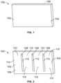
- Figure 1 illustrates a perspective front view of a structure 100, according to an example of the present disclosure.
- the structure 100 is a panel, sheet, or the like.
- the structure 100 is a block, sphere, pyramid, irregularly-shaped structure, or the like.
- the structure 100 can be a flat sheet of material.
- the structure 100 can include one or more curved surfaces.
- the structure 100 includes a first face 102 having an exposed surface 104.
- the first face 102 is coupled to a second face 106 opposite from the first face 102.
- the first face 102 can be a front, rear, top, bottom, lateral, or other such face.
- the surface 104 is an outer surface of the structure 100.
- the structure 100 is formed of a material, such as a plastic, metal, composite, and/or the like.
- the structure 100 can be formed of a thermoplastic, such as nylon, polycarbonate (PC), polypheylsulfone (PPSU), polyetherimide (PEI), or the like.
- the structure 100 can be formed of epoxy, phenolic materials, and/or the like.
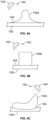
- FIG. 2 illustrates a perspective front view of the structure 100 having liquid flow paths 108 formed through surface treatment, according to an example of the present disclosure.
- the liquid flow paths 108 are examples of liquid management patterns.
- the liquid flow paths 108 are formed on a main body 109, such as between banks 110.
- the liquid flow paths 108 have a first wettability 112 that differs from a second wettability 114 of the remainder of the main body 109, such as the banks 110.
- the first wettability 112 provides increased liquid flow rate as compared to the second wettability 114.
- the first wettability 112 of the liquid flow paths 108 allows for liquid to flow with increased ease as compared to the banks 110.
- the liquid flow paths 108 are configured to divert liquid, such as water, to a desired location, such as a bilge, drain, or the like, such as via gravity.
- Liquid can flow on the banks 110. However, the banks 110 resist liquid flow greater than the liquid flow paths 108.
- structures within an aircraft may vibrate. Due to gravity and vibration during a flight, liquid gathers and flows along the liquid flow paths 108. In at least one example, boundaries between treated and untreated areas provide the banks 110.
- first and second in relation to wettability are merely terms used to differentiate. That is, the first wettability differs from the second wettability.
- the liquid flow paths 108 have increased wettability in comparison to the remainder of the main body 109 of the structure 100, such as that of the banks 110. It is to be understood that the first wettability is not necessarily one of increased wettability.
- the liquid flow paths 108 may have a second wettability that is increased in relation to a first wettability of the banks 110.
- the structure 100 can include more or less liquid flow paths 108 than shown. Further, the liquid flow paths 108 can be sized and shaped differently than shown. For example, the liquid flow paths 108 can be horizontally or diagonally oriented, instead of vertically oriented. As another example, the liquid flow paths 108 can include one or more curved portions, instead of being linear.
- the wettability of a surface relates to surface tension or surface energy of a liquid, such as water. Wettability relates to surface flow resistance.
- increasing wettability of a surface increases a likelihood that the liquid flows over the surface, in contrast to beading up on the surface.
- decreasing wettability of a surface increases a likelihood that the liquid will bead on the surface, as opposed to flowing over the surface.
- increasing the surface flow resistance of a surface decreases a likelihood that liquid flows over the surface, in contrast to beading up on the surface.
- decreasing the surface flow resistance of a surface decreases a likelihood that the liquid will bead on the surface, as opposed to flow over the surface.
- a bank 110 has a higher surface flow resistance than a liquid flow path 108.
- Figure 3A illustrates a flow chart of a method of forming one or more liquid flow paths on a surface of a structure, according to an example of the present disclosure.
- the structure 100 having the surface 104 is provided.
- the surface 104 is treated to provide at least one area having a different wettability than at least one area that is adjacent to the at least one area.
- the surface 104 is treated by printing.
- one or more liquid flow paths 108 are printed on the surface 104.
- the printing provides the liquid flow path(s) 108, while the at least one area that is adjacent to the at least one area can be or include one or more banks 110.
- the one or more liquid flow paths 108 are defined by the treatment of the surface 104, such as via printing.
- the structure 100 can be formed of a thermoplastic or thermoset, such as an epoxy or phenolic material.
- the treatment includes printing.
- the treatment can also include in-mold texturing, bonding, cutting, chemical etching, painting using a blocking layer, and/or the like.
- the structure 100 can be nylon, PC, PPSU, PEI, or the like, and the treatment can also include superficial foaming, bonding, texturing, chemical etching, or the like.
- the treatment, such as printing modifies at least a portion of the surface 104 to define one or more liquid flow paths 108 having a different wettability than a remainder of the main body 109, such as the banks 110.
- treating a portion of the surface 104 of the structure 100 to form one or more liquid flow paths 108 includes printing on the portion, such through three-dimensional printing, ink printing, laser printing, and/or the like, to modify a wettability of the portion.
- the treating can also include one or more of chemically etching the portion to modify a wettability of the portion, and/or superficial foaming the portion to modify a wettability of the portion.
- the treating includes printing on the portion, texturing the portion to modify a wettability of the portion, chemically etching the portion to modify a wettability of the portion, and superficial foaming the portion to modify a wettability of the portion.
- the treatment of the surface 104 also includes superficial foaming.
- a physical foaming agent such as high pressure carbon dioxide gas or supercritical carbon dioxide
- the physical foaming agent can be allowed to remain on the surface 104 for a predetermined period of time to diffuse into the area for a certain depth, such as ten minutes (optionally, the time period can be more or less than ten minutes, such as twenty minutes, or five minutes).
- the physical foaming agent is then removed, and the structure 100 can then be heated leading to superficial foaming, which thereby modifies the areas to a certain depth.
- superficial foaming modifies a wettability of areas of the structure.
- an area to be treated may be sealed locally to maintain a high pressure gas state or supercritical state for the physical foaming agent.
- Figure 3B illustrates a flow chart of a method of forming one or more liquid flow paths on a surface of a structure, according to an example of the present disclosure.
- the structure 100 having the surface 104 with a first wettability is provided.
- the first wettability can be one in which water beads on the surface.
- the first wettability can be a relatively low wettability in that water beads thereon, instead of flowing over the surface 104.
- one or more areas are treated on the surface to alter the first wettability to a second wettability.
- the treatment includes printing.
- the treatment can also include superficial foaming, chemical etching, painting, and/or or the like.
- the one or more areas are desired locations for the liquid flow paths 108.
- the second wettability is greater than the first wettability. That is, the second wettability allows for increased liquid flow, and decreased liquid beading.
- the first wettability can be one in which water tends to flow over, as opposed to bead.
- the first wettability can be a relatively high wettability.
- areas on the surface 104 are treated to alter the first wettability to a second wettability that is less than the first wettability.
- the areas that are formed through surface treatment can be those that are desired to be the banks 110.
- the liquid flow paths 108 are formed between the banks 110.
- Figure 3C illustrates a flow chart of a method of forming one or more liquid management patterns on a surface of a structure, according to an example of the present disclosure.
- the liquid management patterns include one or more liquid retaining patterns.
- the liquid management patterns include one or more liquid flow paths.
- the liquid management patterns include one or more liquid retaining patterns and one or more liquid flow paths.
- the structure 100 having the surface 104 is provided.
- one or more features are printed on the surface 104.
- the one or more features are cured with ultraviolet (UV) light, such as emitted by a UV light emitting device.
- UV ultraviolet
- one or more liquid management patterns such as liquid retaining patterns and/or liquid flow paths 108, are provided via the one or more features, which were cured with by the UV light.
- the method may not include 214. Instead, the feature(s) can be printed on the surface 104 and not cured with UV light.
- the liquid management patterns provide moisture control, such as within an internal cabin of an aircraft.
- the features printed on the surface 104 are configured to retain and/or divert moisture.
- a digital inkjet printer provides the printing, such as via texture printing with UV curable inks, to create protruded features on the surface 104 of the structure 100, which can be a decorative laminate or other substrate to control liquid diverting or wicking.
- condensed moisture is retained on the surfaces to evaporate, be removed later, or be diverted to designated locations, as opposed to dripping on the passengers.
- the features are formed through a printer applying UV curable ink to the surface 104.
- the printer can print banks and valleys for various surface areas, such as within an internal cabin of a vehicle.
- a liquid retaining pattern or liquid flow path(s) 108 is printed directly on a decorative laminate, which can be applied on interior commodities, such as a front face of a stowage bin.
- the decorative laminate is applied on the interior commodities, and the liquid retaining pattern or flow path(s) is printed directly on the decorative laminate.
- the liquid retaining pattern can be configured to retain excess liquid or moisture on the surface, such that it may evaporate, or be removed by crew members.
- the liquid diverting pattern diverts excess liquid or moisture to designated locations to prevent accumulation or dripping into undesired areas.
- the printer can operate to provide a liquid management pattern that is configured to provide wicking via capillary phenomenon.
- the printer may be configured to deposit ink over multiple passes.
- the printer can operate to provide a liquid management pattern that is configured to provide liquid flow paths to divert and guide liquid to desired locations.
- the liquid flow paths can be formed by the printer depositing ink over a single pass.
- a method includes printing one or more features on the surface 104 of the structure 100 of an internal cabin of an aircraft, and providing, by the one or more printed features, one or more liquid management patterns.
- the one or more liquid management patterns include one or more liquid retaining patterns, and/or one or more liquid flow paths.
- the method also includes curing the one or more features with ultraviolet (UV) light.
- UV ultraviolet
- Figure 4A illustrates a transverse cross-sectional view of a feature 130a printed on a surface 104 of a structure 100, according to an example of the present disclosure.
- Figure 4B illustrates a transverse cross-sectional view of a feature 130b printed on a surface 104 of a structure 100, according to an example of the present disclosure.
- Figure 4C illustrates a transverse cross-sectional view of a feature 130c printed on a surface 104 of a structure 100, according to an example of the present disclosure.
- Figures 4A-C show examples of the feature 130a, 130b, and 130c.
- a feature may be sized and shaped differently than shown in Figures 4A-C .
- the features 130a, 130b, and 130c can be formed by a printer depositing ink (such as UV curable ink) onto the surface 104 over one or more passes.
- An emitting device 140 (such as a UV lamp) can then be operated to emit UV light 142 to cure the ink to form a liquid management pattern, such as a liquid retaining pattern, a liquid flow path, and/or the like.
- the feature(s) may not be cured with UV light.
- the features shown in Figures 4A-C are simplified, general shapes. It is to be understood that the features can include different profiles, shapes, rounded portions, and/or the like.
- the feature(s) can be formed to provide liquid wicking via capillary phenomenon.
- the printed features can be 20 um in width and 20 um in height of the print, with a spacing of 20 um.
- Such features can be formed using digitally printed texture for high definition, such as via multiple passes.
- the feature(s) can be formed to provide general liquid diverting/guiding channels.
- the printed features can be 0.5 mm in width and 0.5 mm in height, with a spacing of 0.5 mm.
- Such features can be formed using printing with multi-pass inkjet systems, single pass inkjet systems, and/or coating/varnishing equipment.
- examples of the present disclosure provide methods of forming one or more liquid management patterns, such as liquid retaining patterns(s) and/or liquid flow path(s), on a surface of a structure.
- the method includes providing the structure, and printing one or more features on the surface of the structure to provide the liquid management patterns, which can alter or otherwise modify a wettability thereof.
- a first wettability of the portion of the surface differs from a second wettability of a remainder of the surface.
- the first wettability allows for increased flow of liquid in comparison to the second wettability.
- the first wettability allows for decreased flow of liquid as compared to the second wettability.
- the printing increases the wettability, thereby providing the liquid management patterns at the locations of printed material (for example, at the portion(s) where treated). In at least one other example, the printing decreases the wettability.
- FIG. 5 illustrates a perspective front view of an aircraft 300, according to an example of the present disclosure.
- the aircraft 300 includes a propulsion system 312 that may include two turbofan engines 314, for example.
- the propulsion system 312 may include more engines 314 than shown.
- the engines 314 are carried by wings 316 of the aircraft 300.
- the engines 314 may be carried by a fuselage 318 and/or an empennage 320.
- the empennage 320 may also support horizontal stabilizers 322 and a vertical stabilizer 324.
- the fuselage 318 of the aircraft 300 defines an internal cabin, which may be defined by interior sidewall panels that connect to a ceiling and a floor.
- the internal cabin may include a cockpit, one or more work sections (for example, galleys, personnel carry-on baggage areas, and the like), one or more passenger sections (for example, first class, business class, and coach sections), and an aft section.
- work sections for example, galleys, personnel carry-on baggage areas, and the like
- passenger sections for example, first class, business class, and coach sections
- an aft section Portions of the aircraft 300, such as panels within the internal cabin, can be formed by methods to form liquid management patterns (such as liquid flow paths and/or liquid retaining patterns), as described herein.
- examples of the present disclosure may be used with various other vehicles, such as automobiles, buses, locomotives and train cars, watercraft, spacecraft, and the like.
- methods as described herein can be used to form structures having liquid management patterns for structures within buildings, articles of manufacture, or the like.
- Figure 6 illustrates a perspective view of a panel assembly 400 that forms a portion of wall 402 within an internal cabin of an aircraft, according to an example of the present disclosure.
- the panel assembly 400 includes a plurality of window openings 404.
- the panel assembly 400 may not include window openings.
- the panel assembly 400 includes a first or inner ply 406, which faces the internal cabin.
- An outer surface 408 of the inner ply 406 facing away from the internal cabin may include a lining.
- the lining may be secured to the outer surface 408.
- the panel assembly 400 also includes a second or outer ply 410.
- insulation 412 is secured to an inner surface 414 of the outer ply 410 facing toward the internal cabin.
- the panel assembly 400 may not include the insulation 412.
- An outer surface 416 of the outer ply 410 is opposite from the inner surface 414.
- An air gap 418 may be formed between the inner ply 406 and the outer ply 410.
- the air gap 418 separates the inner ply 406 from the outer ply 410.
- the panel assembly 400 may not include the air gap. Instead, the inner ply 406 may be directly coupled to the outer ply 410.
- one or more surfaces of the panel assembly 400 include liquid management patterns, as described herein.
- the outer surface 408 of the inner ply 406 may include liquid management patterns, as described herein.
- the inner surface 414 of the outer ply 410 may include liquid management patterns.
- both the outer surface 408 of the inner ply 406 and the inner surface 414 of the outer ply 410 may include liquid management patterns.
- inner and outer surfaces of the inner ply 406 and inner and outer surfaces of the outer ply 410 may include liquid management patterns.
- a wall of an internal cabin of an aircraft may include one or more panel assemblies 400.
- various other portions of the aircraft may be formed by one or more panel assemblies 400.
- interior monuments such as lavatories, closets, cabinets, section dividers, and the like may include one or more panel assemblies 400.
- portions of stowage bin assemblies may include one or more panel assemblies 400.
- the panel assemblies 400 may be sized and shaped as desired.
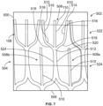
- Figure 7 illustrates a front view of a surface 500 of a panel assembly 502, according to an example of the present disclosure.
- the panel assembly 400 shown in Figure 6 is an example of the panel assembly 502.
- the surface 500 has been treated (such as via printing) to provide a liquid flow path 108, as described herein.
- the surface 500 may be an outer and/or inner surface of an outer ply (such as the outer ply 410 shown in Figure 6 ), an outer and/or inner surface of an inner ply (such as the inner ply 406 shown in Figure 6 ), and/or the like.
- the liquid flow path 108 includes a flow-directing network 504 that is configured to divert liquid to a desired location, such as toward a bottom 506 of the panel assembly 502, via gravity or inertial force.
- the flow-directing network 504 includes a plurality of interconnected flow director elements 508 formed between banks 110.
- the banks 110 provide barriers surrounding the flow-directing network 504.
- the flow-director elements 508 have a first wettability that is configured to allow for fluid flow, while the banks 110 have a second wettability that resists fluid flow.
- the first wettability is associated with a first surface energy.
- the second wettability is associated with a second surface energy, which is lower than the first surface energy (conversely, the first surface energy is higher than the second surface energy).
- the first surface energy provides a smooth surface that allows for fluid flow.
- the second surface energy provides a rough surface (that is, rougher than the smooth surface provided by the first surface energy) that resists fluid flow.
- liquid tends to bead on the banks 110.
- the liquid beads on the banks 110, and moves to the liquid flow paths 108, via gravity, where the liquid then freely flows downwardly, via gravity, towards a desired location, such as towards the bottom 506.
- one or more of the flow director elements 508 includes a central stem 510 connected to a first lateral branch 512 and a second lateral branch 514.
- the central stem 510 provides a longitudinal channel that extends towards the bottom 506.
- the central stem 510 may be a linear channel, formed as described herein.
- the first lateral branch 512 may be a mirror image of the second lateral branch 514.
- the first lateral branch 512 and the second lateral branch 514 include an upper channel 516 that downwardly angles towards the central stem 510.
- the upper channels 516 connect to an inwardly-curved channel 518 (which inwardly curves towards the central stem 510).
- the inwardly-curved channel 518 connects to an outwardly-curved channel 518 that connects to a lower portion of the central stem 510, thereby providing a union 520 between the central stem 510, the first lateral branch 512, and the second lateral branch 514.
- the flow director elements 508 may be sized and shaped differently than shown. In at least one embodiment, the flow director elements 508 include more or less branches. For example, the flow director elements 508 may include two lateral branches on either side of the central stem 510. As another example, the flow director elements 508 may not include the central stem. As another example, the branches 512 and 514 may not be symmetrical about the central stem 510.
- the flow-directing network 504 includes a first row 522 of flow director elements 508 above a second row 524 of flow director elements 508.
- the second row 524 may be above a third row of flow director elements, and so on.
- the flow-directing network 504 may include only a single row of flow director elements 508.
- the panel assembly 502 may include a single flow director element 508.
- the union 520 of a flow director element 508 within the first row 522 connects to (for example, is in fluid communication with) a first lateral branch 512 of a first flow director element 508a of the second row 524 and a second lateral branch 514 of a second flow director element 508b of the second row 524.
- the first lateral branch 512 of the first flow director element 508a is integrally formed and connected with the second lateral branch 514 of the second flow director element 508b.
- flow director elements 508 within the first row 522 may interconnect and cascade with flow director elements 508 of the second row 524 (which may similarly interconnect and cascade with flow director elements 508 of a third row, and so on).
- the flow director elements 508 within the first row 522 may be sized and shaped the same as the flow director elements 508 within the second row 524.
- the flow director elements 508 within the first row 522 may be sized and shaped differently than the flow director elements 508 within the second row 524.
- the central stems 510 and/or the first and second lateral branches 512 and 514 of the flow director elements 508 within the second row 524 may be larger (for example, have increased height and/or area) than those within first row 522, or vice versa.
- the flow director elements 508 within each row may be sized and shaped the same or differently.
- the flow director elements 508 provide a pattern formed by surface treatment, as described herein, that is configured to divert liquid toward a desired location, such as the bottom 506 of the panel assembly 502.
- the sizes and shapes of the flow director elements 508 may vary depending on setting, application, part geometry, part orientation, and/or the like.
- moisture that condenses on the rougher areas, defined by the banks 110 forms beads.
- the external flow of liquid on the banks 110 flows in an uncontrolled manner until it intersects a portion of a flow director element 508, which provides a relatively smooth area that promotes controlled flow of liquid.
- the liquid flows in a controlled manner within the flow director element 508, via gravity, due to the relatively high surface energy of the flow director element 508.
- Adhesion of the liquid to the higher surface energy of the flow director element 508 prevents, minimizes, or otherwise reduces the potential of the liquid flowing onto the banks 110.
- the panel assembly 502 facilitates liquid flow by destabilizing droplet shapes on the roughened areas of the banks 110, allowing inertial forces to dominate surface tension, and promote flow into and through the liquid flow path 108, defined by the one or more flow director elements 508.
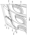
- Figure 8 illustrates a perspective front view of a panel assembly 600, according to an example of the present disclosure.
- the panel assembly 400 shown in Figure 6 and the panel assembly 502 shown in Figure 5 are examples of and/or provide portions of the panel assembly 600 shown in Figure 8 , or vice versa.
- the panel assembly 600 includes a liquid management pattern, such as a liquid flow path 108 formed on a surface 602 thereof.
- the liquid flow path 108 includes a flow-directing network 504 of interconnected and cascading flow director elements 508.
- the flow-directing network 504 includes ten or more rows of interconnected flow director elements 508.
- the flow-directing network 504 may include less than ten rows of interconnected flow director elements 508.
- Liquid on the surface 602 beads on the banks 110 and moves, via gravity or inertial force, into the flow director elements 508.
- the liquid flows downwardly in the direction of arrow A towards a lower drain channel 606 of the flow-directing network 504.
- the lower drain channel 606 is formed in the same manner as the liquid flow directors 508. That is, the lower drain channel 606 has a wettability that promotes liquid flow, in contrast to the banks 110.
- Lower drain channel 606 may include downwardly angled segments 608 that connect to the lowest row 610 of flow director elements 508.
- the segments 608 may, in turn, connect to drain outlets 612.
- the height or area of the flow director elements 508 within higher rows may be less than the height or area of the flow director elements 508 within lower rows. That is, a height of flow director elements in lower rows is greater than a height of flow director elements in upper rows.
- the height of flow director elements may progressively increase as rows descend. For example, the height 620 of the flow director elements 508 within the highest row 622 may be less than the height 624 of the flow director elements 508 within the lowest row 610.
- the increasing height progression from upper to lower rows accommodates and promotes increased flow rates.
- the flow-directing network 504 is circuitous and tortuous, with numerous interconnected and cascading flow director elements 508.
- the multiple potential paths for liquid flow defined by the numerous interconnected flow director elements 508 accommodate an increased volume of flow. That is, flow volume increases with the number of flow director elements 508.
- the interconnected flow director elements 508 define multiple directions for liquid flow, which ensures flow of liquid towards the bottom in the direction of arrow 604, even during orientational changes (such as when an aircraft changes altitude or attitude).
- the various directional changes defined by the numerous flow direction elements 508 within the flow-directing network 504 limit flow inertial velocity, which reduces a potential of a surge flow and/or liquid overflowing the banks 110.
- the panel assembly 600 may be formed of a composite thermoplastic or thermoset, for example.
- the pattern of flow director elements 508 within the flow-directing network 504 may be formed by surface treatment, as described herein.
- the flow director elements 508 may be formed by texture pattern on a forming die, chemical etching on a metallic surface, and/or the like.
- Figure 9 illustrates a perspective internal view of an internal cabin 700 of a vehicle, (such as the aircraft 300 shown in Figure 5 ) according to an example of the present disclosure.
- the internal cabin 700 includes numerous components that may be formed from and/or otherwise include structures, such as the structure 100 shown and described with respect to Figures 2 and 4A-C , panel assemblies, such as the panel assembly 400 (shown in Figure 6 ), the panel assembly 502 (shown in Figure 7 ), and the panel assembly 600 (shown in Figure 8 ), and/or the like.
- ceiling panels 702, stowage bin assemblies 704, sidewall panels 706, ceiling coves 708, doorway arch panels 710, doorway side panels 712, partitions, closets, lavatory walls, light valences, and/or the like may include structure and/or panel assemblies, as described herein.
- FIG 10 illustrates a liquid flow system 800, according to an example of the present disclosure.
- the liquid flow system 800 includes a first panel assembly 802 coupled to a second panel assembly 804, which, in turn, is coupled to a bilge 806, such as a bilge within an aircraft.
- the panel assemblies 802 and 804 are connected in series, with the first panel assembly 802 secured above the second panel assembly 804.
- the first panel assembly 802 includes a flow channel 808 (for example, a liquid flow path) that leads into a flow channel 810 (for example, a liquid flow path) of the second panel assembly 804.
- the flow channel 810 leads into the bilge 806.
- the flow channels 808 and 810 are formed through surface treatment, as described herein.
- the flow channels 808 and 810 may be sized and shaped differently than shown. Further, the liquid flow system 800 may include more or less panel assemblies than shown.
- the liquid flow system 800 such as a flow directing network, may include at least one flow transmission orifice 809 on the boundary of the outer surface of the first panel assembly 802.
- the area may be located and oriented such that liquid from the flow directing network is channeled to the orifice 809 and thus to adjacent aircraft components, such as to the second panel assembly 804.
- the adjacent components may also include flow direction features.
- the flow direction features of the adjacent component may couple to a flow directing network of the first component (for example, the first panel assembly 802).
- the flow directing network on the adjacent component may include a greater capacity such that liquid diverted by the at least one flow transmission orifice of the first component is accommodated along with moisture deposited on the outer surface of the second component from other sources.
- At least two adjacent components with surfaces that include flow directing networks are present such that liquid flows continuously across the outer surfaces of the at least two components.
- the surface of the at least two components may include a moisture control network that directs moisture towards a designated aircraft bilge zone, such as the bilge 806.
- examples of the present disclosure provide structures, panel assemblies, and methods of forming structures that are configured to efficiently manage moisture, such as within an aircraft, for example.
- the structures include liquid management patterns, such as liquid retaining patterns and/or liquid flow paths, that are formed through surface treatment, such as printing.
- Examples of the present disclosure provide lightweight and cost-effective structures that are integrally formed with liquid management patterns. As such, weight for a system can be reduced as there is a reduced need for separate and distinct moisture management devices. Instead, the structures that form portions of a system, such as an aircraft, are integrally formed with their own liquid management patterns.
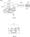
- Figure 11 illustrates a simplified block diagram of a system 900, according to an example of the present disclosure.
- the system 900 is configured to print one or more tactile features 902 on a surface 904 of a component 906.
- the features 902 can provide liquid management patterns, as described herein.
- the surface 904 is an example of the surface 104 shown in Figures 1, 2 , and 4A-C .
- the component 906 is an example of the structure 100 shown in Figures 1, 2 , and 4A-C.
- Figures 4A-C shows examples of the features 902 (such as features 130a, 130b, and 130c).
- Figures 7-10 also show and describe surfaces and features that can be provided by the system 900.
- the component 906 is a portion of a vehicle, such as an outer surface of a fuselage, a wing, or the like.
- the component 906 is within an internal cabin of the vehicle, such as a wall, ceiling, floor, or the like within the vehicle.
- the component 906 can be a structure on or within a fixed structure.
- the component 906 can be a substrate, such as paper, a panel, or the like.
- the surface 904 of the component 906 can be flat and planar.
- the surface 904 can include one more curves, such as can have a regular or irregular curvature.
- the system 900 includes a printer 908 having a print head 910, which includes one or more nozzles 912 configured to deposit ink 914 onto the surface 904.
- the print head 910 includes a single nozzle 912.
- the print head 910 includes two, three, four, five, or more nozzles 912.
- a swath 916 of the print head 910 is a width across the one or more nozzles 912.
- the printer 908 is coupled to an actuator 918, which is configured to move the print head 910.
- the print head 910 includes a single axis servo motor having a linear actuator.
- the actuator 918 is configured to move the print head 910 over a pass in relation to the surface 904 of the component 906.
- the actuator 918 can be separate and distinct from the printer 908.
- the printer 908 includes the actuator 918.
- a control unit 920 is in communication with the printer 908 and the actuator 918, such as through one or more wired or wireless connections.
- the control unit 920 is configured to operate the actuator 918 and the printer 908 to form the tactile features 902 on the surface 904 of the component 906 based on data 922 stored within a memory 924 that is communication with the control unit 920, such as through one or more wired or wireless connections.
- the data 922 can be a bit map of the tactile features 902 to be formed on the surface 904 of the component 906.
- the memory 924 can be separate and distinct from the control unit 920.
- the control unit 920 includes the memory 924.
- the printer 908 In operation, in order to form the tactile features 902, the printer 908 is moved in a single pass in the direction of arrow A (such as from left to right, right to left, top to bottom, or bottom to top) in relation to the surface 904.
- the control unit 920 operates the printer 908 to deposit the ink 914 onto the surface 904 to form the tactile features 902 during the single pass of the printer 908.
- the control unit 920 varies the speed of the printer 908 in the direction of arrow A during the single pass, instead of operating the printer over multiple passes.
- the printing can include multiple passes to form the textured features.
- the printing can include a constant speed, or a variable speed.
- control unit 920 can operate the printer 908 to form various features on structures.
- the control unit 920 can operate the printer 908 to form various liquid management patterns (such as liquid retaining patterns, liquid flow paths, and/or the like) as shown and described with respect to Figures 2-4C , 7 , 8 , and 10 .
- Figure 12 illustrates a simplified lateral view of the component 906, according to an example of the present disclosure.
- the control unit 920 operates the printer 908 to form the tactile features 902a and 902b during a single pass of the print head 910 in the direction of arrow A.
- the tactile feature 902a has a first width W1 along a portion of the surface 904, and a first height H1 above the surface 104.
- the tactile feature 902a has a second width W2 along a portion of the surface 904, and a second height H2 above the surface 904.
- the first width W1 differs from the second width W2.
- the first width W1 is greater than the second width W2.
- the first height H1 differs from the second height H2.
- the first height H1 is less than the second height H2.
- the control unit 920 decreases the speed of the print head 910 during the single pass in the direction of arrow A, thereby concentrating more ink droplets at a tighter location. Consequently, the ink droplets form the higher, thinner tactile feature 902b.
- the control unit 920 increases the speed of the print head 910 during the single pass in the direction of arrow A, thereby spreading the ink droplets over a wider area, and which reduces the build-up in height.
- control unit 920 operates the printer 908 to form tactile features 902 having different attributes (such as different heights and/or widths) on the surface 904 of the component 906 by varying the speed of the print head 910, as controlled by the actuator 918, during the single pass in the direction of arrow A.
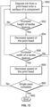
- Figure 13 illustrates a flow chart of a method, according to an example of the present disclosure.
- the control unit 920 operates the printer 908 to deposit the ink 914 from the print head 910 onto the surface 904 of the component 906.
- the control unit 920 determines, such as via the data 922 in the memory 924, if a height of a tactile feature 902 to be printed on the surface 904 is to be increased. If not, the method returns to 950 (or proceeds to 956).
- the control unit 920 decreases the speed of the print head 910 (via operation of the actuator 918) during the single pass in the direction of arrow A, thereby building up an increased amount of ink at a particular location (defined by the data 922) to form the tactile feature 902.
- Such a feature can have a reduced width.
- control unit 920 determines, such as via the data 922 in the memory, if a width of a tactile feature 902 to be printed on the surface 904 is to be increased. Step 956 can occur before 952. The method can include step 956 and not step 952, or vice versa.
- the method can return to 950, or optionally proceed to 960. If, however, the width of the tactile feature 902 is to be increased (and the height reduced), the method proceeds from 956 to 958, at which the control unit 920 increases the speed of the print head 910 (via operation of the actuator 918) during the single pass in the direction of arrow A to form the tactile feature 902. Such a feature can have a reduced height.
- the control unit 920 determines if the single pass is complete. If not, the method returns to 950. If, however, the control unit 920 determines that the single pass is complete, the method proceeds from 960 to 962, at which the method ends.
- control unit 920 is configured to vary a speed of the print head 910 of the printer 908 during a single pass in the direction of arrow A to form tactile features 902 having different attributes, such as different heights and/or different widths.
- control unit 920 can form such tactile features 902 by varying the speed of the print head 910 using additional passes in the direction of arrow A, the opposite of arrow A, and/or the like.
- control unit 920 is configured to operate the printer to build tactile textured features 902 in a single pass of the print head 910 in the direction of arrow A.
- the control unit 920 instead of using an established print clock from an encoder pulse train, the control unit 920 maintains the print clock at a frequency that optimizes head acoustics.
- the control unit 920 can then operate the printer 908 to form the tactile features 902 through the data 922 and varying the speed of the print head 910. Faster print speeds create a shorter texture (that is, a reduced height) while slower print speeds create a taller texture (that is, an increased height).
- the data 922 such as bit map data, accounts for any complex curvature of the surface 904 to achieve a desired printed output.
- the desired output display to be formed on the surface 904 (such as printed text, images, graphics, and/or the like) is stored as the data 922 within the memory 924.
- the output display can be created through one or more steps, which can be conducted by the control unit 920.
- the output display can be created through unit vector mesh unwrapping and image texturing in conjunction with pixel clustering in relation to print speed.
- the control unit 920 sets the print clock set to a specific frequency that optimizes acoustics of the print head 910, such as 30k Hz.
- the control unit 920 constantly sends a 30kHz print clock to the print head 910. Consequently, when printing at different speeds, tactile features 902 having different attributes are formed.
- the tactile features 902 are created in a single pass when jetting at a constant print frequency using an ultraviolet curable translucent ink.
- the speed of the print head 910 dictates the height of the tactile features 902.
- control unit 920 operates the printer 908 to constantly jet the ink 914 from the nozzle(s) 912 during the single pass in the direction of arrow A.
- control unit 920 synchronizes the speed of the print head 910 with the data 922, such as the bit map data, to enable single pass complex curvature textured printing.
- the control unit 920 operates to vary the attributes (for example, heights and/or widths) of the tactile features 902 by controlling the speed of the print head 910 in the direction of arrow A in accordance with the data 922.
- the speed of the print head 910 is varied during the single pass in the direction of arrow A to vary attributes of the tactile features 902.
- the systems and methods described here can be used to print tactile features 902 on complex curved surfaces, such as within an internal cabin of a commercial aircraft.
- the systems and methods described herein can be used in place of traditional embossing processes.
- control unit 920 is configured to operate the printer 908 to form the tactile features 902 on a curved surface.
- the control unit analyzes the shape of the curved surface, and provides a unit vector map of the curved surface, such as in a two dimensional plane. By unit vector mapping the curved surface, the control unit 920 ensures that the formed tactile features 902 on the curved surface are accurate and undistorted.
- examples of the present disclosure provide a method including controlling, by the control unit 920, the printer 908 to form one or more tactile features 902 on the surface 904 of the component 906.
- the tactile features 902 provide liquid management patterns (such as liquid retaining patterns and/or liquid flow paths) on a surface of a structure of a vehicle, such as an aircraft.
- Said controlling includes varying a speed of the print head 910 of the printer 908 to vary one or more attributes of the one or more tactile features 902.
- said varying the speed includes varying the speed of the print head 910 of the printer 908 during a single pass of the print head 910 in relation to the surface 904 of the component 906.
- the one or more tactile features 902 include a plurality of tactile features 902. At least two of the plurality of tactile features 902 differ in relation to the one or more attributes. For example, the two different tactile features 902 can have different heights, and/or different widths.
- the attributes include one or both of height or width.
- said varying the speed includes reducing the speed of the print head 910 to form the one or more tactile features 902 having an increased height.
- the one or more tactile features 902 can also have a reduced width.
- said varying the speed includes increasing the speed of the print head 910 to form the one or more tactile features 902 having an increased width.
- the one or more tactile features 902 can also have a reduced height.
- control unit central processing unit
- CPU central processing unit
- computer computer
- RISC reduced instruction set computers
- ASICs application specific integrated circuits
- the control unit 920 may be or include one or more processors that are configured to control operation, as described herein.
- the control unit 920 is configured to execute a set of instructions that are stored in one or more data storage units or elements (such as one or more memories), in order to process data.
- the control unit 920 may include or be coupled to one or more memories.
- the data storage units may also store data or other information as desired or needed.
- the data storage units may be in the form of an information source or a physical memory element within a processing machine.
- the set of instructions may include various commands that instruct the control unit 920 as a processing machine to perform specific operations such as the methods and processes of the various examples of the subject matter described herein.
- the set of instructions may be in the form of a software program.
- the software may be in various forms such as system software or application software. Further, the software may be in the form of a collection of separate programs, a program subset within a larger program, or a portion of a program.
- the software may also include modular programming in the form of object-oriented programming.
- the processing of input data by the processing machine may be in response to user commands, or in response to results of previous processing, or in response to a request made by another processing machine.
- the diagrams of examples herein may illustrate one or more control or processing units, such as the control unit 920.
- the processing or control units may represent circuits, circuitry, or portions thereof that may be implemented as hardware with associated instructions (e.g., software stored on a tangible and non-transitory computer readable storage medium, such as a computer hard drive, ROM, RAM, or the like) that perform the operations described herein.
- the hardware may include state machine circuitry hardwired to perform the functions described herein.
- the hardware may include electronic circuits that include and/or are connected to one or more logic-based devices, such as microprocessors, processors, controllers, or the like.
- control unit 920 may represent processing circuitry such as one or more of a field programmable gate array (FPGA), application specific integrated circuit (ASIC), microprocessor(s), and/or the like.
- FPGA field programmable gate array
- ASIC application specific integrated circuit
- microprocessor(s) and/or the like.
- the circuits in various examples may be configured to execute one or more algorithms to perform functions described herein.
- the one or more algorithms may include aspects of examples disclosed herein, whether or not expressly identified in a flowchart or a method.
- the terms "software” and “firmware” are interchangeable, and include any computer program stored in a data storage unit (for example, one or more memories) for execution by a computer, including RAM memory, ROM memory, EPROM memory, EEPROM memory, and non-volatile RAM (NVRAM) memory.
- a data storage unit for example, one or more memories
- NVRAM non-volatile RAM
- the above data storage unit types are exemplary only, and are thus not limiting as to the types of memory usable for storage of a computer program.
- examples of the present disclosure provide efficient moisture management within an aircraft. Further, examples of the present disclosure provide efficient methods of forming structures that are configured to manage moisture. Also, examples of the present disclosure provide systems and methods for efficiently and effectively printing features on a surface of component. Additionally, examples of the present disclosure provide methods of printing features that are faster than conventional methods of using multiple passes of a print head.
- a structure, limitation, or element that is "configured to” perform a task or operation is particularly structurally formed, constructed, or adapted in a manner corresponding to the task or operation.
- an object that is merely capable of being modified to perform the task or operation is not “configured to” perform the task or operation as used herein.
Landscapes
- Engineering & Computer Science (AREA)
- Mechanical Engineering (AREA)
- Aviation & Aerospace Engineering (AREA)
- Physics & Mathematics (AREA)
- Fluid Mechanics (AREA)
- General Engineering & Computer Science (AREA)
- Manufacturing & Machinery (AREA)
Applications Claiming Priority (1)
| Application Number | Priority Date | Filing Date | Title |
|---|---|---|---|
| US18/458,245 US20230398568A1 (en) | 2020-02-11 | 2023-08-30 | Methods for forming liquid management patterns on a surface of a structure of a vehicle |
Publications (1)
| Publication Number | Publication Date |
|---|---|
| EP4516518A1 true EP4516518A1 (de) | 2025-03-05 |
Family
ID=92172176
Family Applications (1)
| Application Number | Title | Priority Date | Filing Date |
|---|---|---|---|
| EP24192035.4A Pending EP4516518A1 (de) | 2023-08-30 | 2024-07-31 | Verfahren zur bildung von flüssigkeitsverwaltungsmustern auf einer oberfläche einer struktur eines fahrzeugs |
Country Status (1)
| Country | Link |
|---|---|
| EP (1) | EP4516518A1 (de) |
Citations (5)
| Publication number | Priority date | Publication date | Assignee | Title |
|---|---|---|---|---|
| US20060068109A1 (en) * | 2004-09-15 | 2006-03-30 | Airbus Deutschland Gmbh | Painting device, painting arrangement, method for painting a curved surface of an object, and use of an inkjet device for painting an aircraft |
| EP2982599A1 (de) * | 2014-08-01 | 2016-02-10 | The Boeing Company | In eine lackschicht integrierte widerstandsreduzierungsriblets |
| EP3693270A1 (de) * | 2019-02-08 | 2020-08-12 | The Boeing Company | Verfahren zur oberflächenmikrotexturierung mit einem ablationsmittel |
| US20210245859A1 (en) * | 2020-02-11 | 2021-08-12 | The Boeing Company | Liquid-diverting panel assemblies and methods |
| US11155035B2 (en) * | 2016-05-31 | 2021-10-26 | Nike, Inc. | Method of printing a contoured object using color and structural layers |
-
2024
- 2024-07-31 EP EP24192035.4A patent/EP4516518A1/de active Pending
Patent Citations (5)
| Publication number | Priority date | Publication date | Assignee | Title |
|---|---|---|---|---|
| US20060068109A1 (en) * | 2004-09-15 | 2006-03-30 | Airbus Deutschland Gmbh | Painting device, painting arrangement, method for painting a curved surface of an object, and use of an inkjet device for painting an aircraft |
| EP2982599A1 (de) * | 2014-08-01 | 2016-02-10 | The Boeing Company | In eine lackschicht integrierte widerstandsreduzierungsriblets |
| US11155035B2 (en) * | 2016-05-31 | 2021-10-26 | Nike, Inc. | Method of printing a contoured object using color and structural layers |
| EP3693270A1 (de) * | 2019-02-08 | 2020-08-12 | The Boeing Company | Verfahren zur oberflächenmikrotexturierung mit einem ablationsmittel |
| US20210245859A1 (en) * | 2020-02-11 | 2021-08-12 | The Boeing Company | Liquid-diverting panel assemblies and methods |
Similar Documents
| Publication | Publication Date | Title |
|---|---|---|
| EP3865397B1 (de) | Flüssigkeitsableitende paneelanordnungen und verfahren | |
| EP2891606B1 (de) | Strömungskörper, Verfahren zur Herstellung eines Strömungskörpers und Flugzeug mit solch einem Strömungskörper | |
| EP2511175B1 (de) | Vorrichtung und Verfahren zur Lärm- und Wirbelminderung von Flugzeugen | |
| US9511848B2 (en) | Profile plate portion for use as an outer wall of a flow body, method for manufacturing a profile plate portion and flow body component comprising a suction-extraction device for fluid | |
| JP6951108B2 (ja) | 多層リブレットアップリケおよびその作製方法 | |
| US8336828B2 (en) | Traversing jet actuator | |
| CA2883992C (en) | Structure and method for reducing air flow in a wall volume of an aircraft | |
| WO2009023354A2 (en) | Passive removal of suction air for laminar flow control, and associated systems and methods | |
| US8220741B2 (en) | Synthetic aisle configuration for an aircraft | |
| US20190193829A1 (en) | Aircraft and method for producing an aircraft | |
| US20170326837A1 (en) | Methods and apparatus to vent gas and vapor from a panel via venting channels for a decorative layer | |
| EP4516518A1 (de) | Verfahren zur bildung von flüssigkeitsverwaltungsmustern auf einer oberfläche einer struktur eines fahrzeugs | |
| US20230398568A1 (en) | Methods for forming liquid management patterns on a surface of a structure of a vehicle | |
| US6817571B2 (en) | Integrated aircraft windshields and associated methods | |
| Howe | Blended wing body airframe mass prediction | |
| US12187440B2 (en) | Air curtain systems and methods for internal cabins of vehicles | |
| US12269574B2 (en) | Methods for forming liquid flow paths on a surface of a structure | |
| Shmilovich et al. | Strategies for practical implementations of low-input thermal flow control | |
| Nagel et al. | Conceptual aerodynamic evaluation of MINI/MICRO UAV | |
| US20250303632A1 (en) | Systems and methods for applying a tactile textured substrate to a surface of a structure | |
| US20240308203A1 (en) | Systems and methods for printing a tactile textured surface on a surface of a component | |
| EP3730284B1 (de) | Verbundtafelsysteme und -verfahren | |
| EP4541599A1 (de) | Systeme und verfahren zum drucken auf einem substrat | |
| US10850829B2 (en) | Aerodynamic flap support structure | |
| Saeed et al. | Conceptual design for a laminar flying wing aircraft |
Legal Events
| Date | Code | Title | Description |
|---|---|---|---|
| PUAI | Public reference made under article 153(3) epc to a published international application that has entered the european phase |
Free format text: ORIGINAL CODE: 0009012 |
|
| STAA | Information on the status of an ep patent application or granted ep patent |
Free format text: STATUS: THE APPLICATION HAS BEEN PUBLISHED |
|
| AK | Designated contracting states |
Kind code of ref document: A1 Designated state(s): AL AT BE BG CH CY CZ DE DK EE ES FI FR GB GR HR HU IE IS IT LI LT LU LV MC ME MK MT NL NO PL PT RO RS SE SI SK SM TR |
|
| STAA | Information on the status of an ep patent application or granted ep patent |
Free format text: STATUS: REQUEST FOR EXAMINATION WAS MADE |
|
| 17P | Request for examination filed |
Effective date: 20250806 |