EP4516517A1 - Printing device and printing method - Google Patents
Printing device and printing method Download PDFInfo
- Publication number
- EP4516517A1 EP4516517A1 EP23796364.0A EP23796364A EP4516517A1 EP 4516517 A1 EP4516517 A1 EP 4516517A1 EP 23796364 A EP23796364 A EP 23796364A EP 4516517 A1 EP4516517 A1 EP 4516517A1
- Authority
- EP
- European Patent Office
- Prior art keywords
- ink
- energy
- ink ribbon
- heating
- layer
- Prior art date
- Legal status (The legal status is an assumption and is not a legal conclusion. Google has not performed a legal analysis and makes no representation as to the accuracy of the status listed.)
- Pending
Links
Images



Classifications
-
- B—PERFORMING OPERATIONS; TRANSPORTING
- B41—PRINTING; LINING MACHINES; TYPEWRITERS; STAMPS
- B41J—TYPEWRITERS; SELECTIVE PRINTING MECHANISMS, i.e. MECHANISMS PRINTING OTHERWISE THAN FROM A FORME; CORRECTION OF TYPOGRAPHICAL ERRORS
- B41J2/00—Typewriters or selective printing mechanisms characterised by the printing or marking process for which they are designed
- B41J2/315—Typewriters or selective printing mechanisms characterised by the printing or marking process for which they are designed characterised by selective application of heat to a heat sensitive printing or impression-transfer material
- B41J2/32—Typewriters or selective printing mechanisms characterised by the printing or marking process for which they are designed characterised by selective application of heat to a heat sensitive printing or impression-transfer material using thermal heads
- B41J2/325—Typewriters or selective printing mechanisms characterised by the printing or marking process for which they are designed characterised by selective application of heat to a heat sensitive printing or impression-transfer material using thermal heads by selective transfer of ink from ink carrier, e.g. from ink ribbon or sheet
-
- B—PERFORMING OPERATIONS; TRANSPORTING
- B41—PRINTING; LINING MACHINES; TYPEWRITERS; STAMPS
- B41J—TYPEWRITERS; SELECTIVE PRINTING MECHANISMS, i.e. MECHANISMS PRINTING OTHERWISE THAN FROM A FORME; CORRECTION OF TYPOGRAPHICAL ERRORS
- B41J2/00—Typewriters or selective printing mechanisms characterised by the printing or marking process for which they are designed
- B41J2/315—Typewriters or selective printing mechanisms characterised by the printing or marking process for which they are designed characterised by selective application of heat to a heat sensitive printing or impression-transfer material
- B41J2/32—Typewriters or selective printing mechanisms characterised by the printing or marking process for which they are designed characterised by selective application of heat to a heat sensitive printing or impression-transfer material using thermal heads
- B41J2/35—Typewriters or selective printing mechanisms characterised by the printing or marking process for which they are designed characterised by selective application of heat to a heat sensitive printing or impression-transfer material using thermal heads providing current or voltage to the thermal head
- B41J2/355—Control circuits for heating-element selection
- B41J2/3551—Block driving
-
- B—PERFORMING OPERATIONS; TRANSPORTING
- B41—PRINTING; LINING MACHINES; TYPEWRITERS; STAMPS
- B41J—TYPEWRITERS; SELECTIVE PRINTING MECHANISMS, i.e. MECHANISMS PRINTING OTHERWISE THAN FROM A FORME; CORRECTION OF TYPOGRAPHICAL ERRORS
- B41J2/00—Typewriters or selective printing mechanisms characterised by the printing or marking process for which they are designed
- B41J2/315—Typewriters or selective printing mechanisms characterised by the printing or marking process for which they are designed characterised by selective application of heat to a heat sensitive printing or impression-transfer material
- B41J2/32—Typewriters or selective printing mechanisms characterised by the printing or marking process for which they are designed characterised by selective application of heat to a heat sensitive printing or impression-transfer material using thermal heads
- B41J2/35—Typewriters or selective printing mechanisms characterised by the printing or marking process for which they are designed characterised by selective application of heat to a heat sensitive printing or impression-transfer material using thermal heads providing current or voltage to the thermal head
- B41J2/355—Control circuits for heating-element selection
- B41J2/3558—Voltage control or determination
-
- B—PERFORMING OPERATIONS; TRANSPORTING
- B41—PRINTING; LINING MACHINES; TYPEWRITERS; STAMPS
- B41J—TYPEWRITERS; SELECTIVE PRINTING MECHANISMS, i.e. MECHANISMS PRINTING OTHERWISE THAN FROM A FORME; CORRECTION OF TYPOGRAPHICAL ERRORS
- B41J31/00—Ink ribbons; Renovating or testing ink ribbons
-
- B—PERFORMING OPERATIONS; TRANSPORTING
- B41—PRINTING; LINING MACHINES; TYPEWRITERS; STAMPS
- B41J—TYPEWRITERS; SELECTIVE PRINTING MECHANISMS, i.e. MECHANISMS PRINTING OTHERWISE THAN FROM A FORME; CORRECTION OF TYPOGRAPHICAL ERRORS
- B41J33/00—Apparatus or arrangements for feeding ink ribbons or like character-size impression-transfer material
- B41J33/14—Ribbon-feed devices or mechanisms
Definitions
- the present invention relates to a printing device and a printing method.
- Patent Document 1 discloses a thermal transfer color printer that prints on paper using a plurality of ink ribbons of different colors.
- This thermal transfer color printer has a plurality of thermal heads that have a one-on-one correspondence to the plurality of ink ribbons.
- the thermal heads heat the corresponding ink ribbons to transfer ink onto paper.
- Multicolor printing is performed by sequentially transferring ink in different colors onto the paper from the plurality of ink ribbons.
- the thermal transfer color printer described above requires a plurality of ink ribbons and a plurality of thermal heads to achieve multicolor printing. This is problematic in that the configuration of the color printer is complex. Moreover, the printer body must be large to accommodate the plurality of ink ribbons and the plurality of thermal heads. Additionally, maintenance such as the replacement of ink ribbons and thermal heads is time-consuming.
- An object of the present invention is to provide a printing device capable of performing multicolor printing and having a simplified configuration that enables the device to be more compact and easier to maintain, and a method of printing with the printing device.
- the present disclosure provides a printing device.
- the printing device includes a first conveying member, a second conveying member, a line thermal head, a transfer member, and a processor.
- the first conveying member is configured to convey an ink ribbon in a sub-scanning direction.
- the ink ribbon includes a base layer, a first ink layer having a first ink, and a second ink layer having a second ink different from the first ink.
- the base layer, the first ink layer, and the second ink layer are overlaid in this order.
- the second conveying member is configured to convey, in the sub-scanning direction, a printing medium that is overlaid on the ink ribbon and faces the second ink layer.
- the line thermal head has a plurality of heating elements arranged in a main scanning direction orthogonal to the sub-scanning direction.
- the plurality of heating elements is configured to be in contact with the ink ribbon from the base layer side to heat the ink ribbon while the ink ribbon is conveyed by the first conveying member.
- the transfer member is positioned downstream of the line thermal head in the sub-scanning direction. The transfer member is configured to transfer both the first ink and the second ink from the ink ribbon onto the printing medium or transfer the second ink from the ink ribbon heated by the line thermal head onto the printing medium, by separating the ink ribbon conveyed by the first conveying member from the printing medium.
- the processor is configured to control the first conveying member, the second conveying member, the line thermal head, and the transfer member.
- the processor is configured to perform: a first heating operation supplying a first energy to a first heating element to heat the ink ribbon, the first heating element being one of the plurality of heating elements; and a second heating operation supplying a second energy to a second heating element to heat the ink ribbon, the second energy being different from the first energy, the second heating element being one of the plurality of heating elements and different from the first heating element.
- the transfer member transfers both the first ink and the second ink onto the printing medium from the ink ribbon heated through the first heating operation.
- the transfer member transfers the second ink onto the printing medium from the ink ribbon heated through the second heating operation.
- the printing device can transfer both the first ink and second ink to the printing medium and transfer the second ink to the printing medium. Accordingly, the printing device can perform multicolor printing using one ink ribbon and one line thermal head, thereby simplifying the device configuration.
- the printing device can print a pattern using the first ink and a pattern using the second ink within a single line extending in the main scanning direction at a time. Accordingly, the printing device can achieve multicolor printing through a simplified configuration. Hence, it is possible to provide a printing device that is compact and easy to maintain.
- the second energy is greater than the first energy.
- the printing device can perform multicolor printing in a case where the necessary energy to transfer the second ink to the printing medium (the second energy) is greater than the necessary energy to transfer both the first ink and the second ink to the printing medium (the first energy).
- the first heating operation supplies the first energy to the first heating element by supplying a first power for a first time
- the second heating operation supplies the second energy to the second heating element by supplying the first power for a second time longer than the first time.
- the printing device can produce the second energy higher than the first energy without modifying the power supplied to the plurality of heating elements.
- the first heating operation supplies the first energy to the first heating element by supplying a first power for a first time
- the second heating operation supplies the second energy to the second heating element by supplying a second power for the first time, the second power being greater than the first power.
- the printing device can produce the second energy higher than the first energy without modifying the time for which the power is supplied to the plurality of heating elements.
- the first heating operation supplies the first energy to the first heating element by supplying a first power for a first time
- the second heating operation supplies the second energy to the second heating element by supplying the first power for a second time shorter than the first time.
- the printing device can produce the second energy lower than the first energy without modifying the power supplied to the plurality of heating elements.
- the first heating operation supplies the first energy to the first heating element by supplying a first power for a first time
- the second heating operation supplies the second energy to the second heating element by supplying a second power for the first time, the second power being smaller than the first power.
- the printing device can produce the second energy lower than the first energy without modifying the time for which the power is supplied to the plurality of heating elements.
- the printing device of the first aspect that in a case where the first heating operation heats the ink ribbon, a bond strength between the base layer and the first ink layer becomes smaller than both a bond strength between the first ink layer and the second ink layer and a bond strength between the second ink layer and the printing medium, and in a case where the second heating operation heats the ink ribbon, the bond strength between the first ink layer and the second ink layer becomes smaller than both the bond strength between the base layer and the first ink layer and the bond strength between the second ink layer and the printing medium.
- a printing device 1 according to an embodiment of the present invention will be described while referring to the accompanied drawings.
- the accompanied drawings are just an example for illustrating technical features that may be employed in the present invention, but the present invention should not be limited only to the configuration illustrated in the drawings.
- the roll support 21 rotatably supports the core of the roll MR.
- the platen 22 rotates when driven by a motor 44 described later (see Fig. 6 ) while in contact with the printing medium M. As a result, the platen 22 draws the printing medium M off the roll MR and conveys the printing medium M toward a discharge unit 10 provided in a housing 11 of the printing device 1.
- the conveying direction of the printing medium M corresponds to a sub-scanning direction.
- the base layer 70 contains a base material 70A made of PET.
- the first ink layer 71 contains a first ink 71A.
- the second ink layer 72 contains a second ink 72A that is different from the first ink 71A.
- the intermediate layer 73 is interposed between the first ink layer 71 and second ink layer 72.
- the printing medium M is overlaid on the ink ribbon R and faces the second ink layer 72, as illustrated in Fig. 4A .
- the plurality of heating elements 5A in the thermal head 5 are arranged at positions where the plurality of heating elements 5A faces the base layer 70 of the ink ribbon R and is in contact with the base layer 70.
- the printing device 1 changes whether both the first ink 71A of the first ink layer 71 and the second ink 72A of the second ink layer 72 are transferred onto the printing medium M from the ink ribbon R (see Fig. 4B ) or the second ink 72A of the second ink layer 72 is transferred onto the printing medium M from the ink ribbon R (see Fig. 4C ).
- the ink ribbon peeling member 33 peels the ink ribbon R off the printing medium M
- the ink ribbon R breaks apart between the base layer 70 and first ink layer 71 where the bond strength is relatively low.
- the first ink 71A of the first ink layer 71, the intermediate layer 73, and the second ink 72A of the second ink layer 72 are transferred to the printing medium M from the ink ribbon R, which has been heated by the first heating elements.
- the first ink 71A is exposed, producing a printing pattern on the printing medium M in the color of the first ink 71A.
- the printing device 1 heats the ink ribbon R by supplying a second energy E2 different from the first energy E1 to some of the plurality of heating elements 5A in the thermal head 5 different from the first heating elements (hereinafter called the "second heating elements").
- the bond strength C2 between the first ink layer 71 and second ink layer 72 becomes lower than the bond strength C1 between the base layer 70 and first ink layer 71 and the bond strength C3 between the second ink layer 72 and printing medium M, as illustrated in Fig. 4C .
- the ink ribbon peeling member 33 peels the ink ribbon R off the printing medium M
- the ink ribbon R breaks apart at the intermediate layer 73, i.e., between the first ink layer 71 and second ink layer 72 where the bond strength is relatively low.
- a portion of the intermediate layer 73 and the second ink 72A of the second ink layer 72 are transferred to the printing medium M from the ink ribbon R, which has been heated by the second heating elements.
- the second ink 72A is exposed through the intermediate layer 73, producing a printed pattern on the printing medium M in the color of the second ink 72A.
- the printing device 1 supplies the first energy E1 to first heating elements 51 and supplies the second energy E2 to second heating elements 52 among the plurality of heating elements 5A in the thermal head 5, as shown in Fig. 2B .
- the "AB" portion of the printing pattern "ABCD” aligned in the main scanning direction appears in the color of the first ink 71A while the "CD” portion appears in the color of the second ink 72A.
- the printing device 1 supplies the first energy E1 to first heating elements 51A and 51B and supplies the second energy E2 to second heating elements 52A and 52B among the plurality of heating elements 5A in the thermal head 5, as illustrated in Fig. 2C .
- the "A" and “C” portions of the printing pattern "ABCD" aligned in the main scanning direction appear in the color of the first ink 71A, while the “B” and “D” portions appear in the color of the second ink 72A.
- the printing device 1 can quickly print a printing pattern using inks of different types along the main scanning direction.
- the printing device 1 changes the respective supply conditions for the first energy E1 supplied to the first heating elements of the thermal head 5 and the second energy E2 supplied to the second heating elements according to the type of ink ribbon R being used. Below, first through fourth supply conditions will be described with reference to Fig. 5 .
- the second energy E2 is greater than the first energy E1 (E1 ⁇ E2), as with the first supply condition. Further, the printing device 1 supplies the first energy E1 to each of the first heating elements by supplying a first power P1 for a first time T1. On the other hand, the printing device 1 supplies the second energy E2 to each of the second heating elements by supplying a second power P2 greater than the first power P1 (P1 ⁇ P2) for the first time T1.
- the second energy E2 is smaller than the first energy E1 (E1>E2). Further, the printing device 1 supplies the first energy E1 to each of the first heating elements by supplying a first power P1 for a first time T1. On the other hand, the printing device 1 supplies the second energy E2 to each of the second heating elements by supplying the first power P1 for a second time T2 shorter than the first time T1 (T1>T2).
- the second energy E2 is smaller than the first energy E1 (E1>E2), as with the third supply condition. Further, the printing device 1 supplies the first energy E1 to each of the first heating elements by supplying a first power P1 for a first time T1. On the other hand, the printing device 1 supplies the second energy E2 to each of the second heating elements by supplying a second power P2 smaller than the first power P1 (P1>P2) for the first time T1.
- the printing device 1 has a CPU 41, a storage 42, an input unit 43, motors 44 and 45, and a driver 46.
- the CPU 41 manages overall control of the printing device 1.
- the storage 42 stores programs to be executed by the CPU 41, print data, and the like.
- the input unit 43 includes switches for configuring various settings on the printing device 1.
- the motor 44 is driven to rotate the platen 22, whereby the platen 22 conveys the printing medium M in the conveying direction.
- the motor 45 is driven to rotate the ribbon take-up spool 32 so that the ribbon take-up spool 32 conveys the portion of the ink ribbon R that is in contact with the printing medium M, i.e., the portion of the ink ribbon R between the ribbon supply spool 31 and the ink ribbon peeling member 33, in the conveying direction.
- the driver 46 drives the thermal head 5 to selectively heat each of the plurality of heating elements 5A.
- the printing device 1 can transfer both the first ink 71A and second ink 72A to the printing medium M and transfer the second ink 72A to the printing medium M. Accordingly, the printing device 1 can perform multicolor printing using one ink ribbon R and one thermal head 5, thereby simplifying the device configuration.
- the printing device 1 can print one line extending in the main scanning direction at a time. Accordingly, the printing device 1 can print a pattern using the first ink and a pattern using the second ink within a single line.
- the printing device 1 can achieve multicolor printing through a simplified configuration, making it possible to provide a printing device 1 that is compact and easy to maintain.
- the ink ribbon R need not possess the intermediate layer 73.
- the first ink layer 71 and second ink layer 72 may be in contact with each other.
- a welding layer including a welding material may be interposed between the base layer 70 and the first ink layer 71.
- the bond strength between the base layer 70 and the first ink layer 71 may be adjusted by the welding layer.
- a backing layer may be provided on the opposite side surface of the base layer 70 from the first ink layer 71.
- an adhesive layer may be provided on the second ink layer 72 on at least one of the first ink layer 71 side and the opposite side.
- Energy may be supplied to the plurality of heating elements 5A by continuously supplying a prescribed power P (the first power P1 or second power P2) for the prescribed time T (the first time T1 or second time T2) or may be supplied according to a different method.
- the prescribed power P may be supplied intermittently to the plurality of heating elements 5A.
- the prescribed time T is the total supply time of the intermittent power supply. The period for these intermittent supply of power P may be constant or not constant.
- Each of the plurality of heating elements 5A may be configured with variable resistance.
- the printing device 1 may adjust the power supplied to the plurality of heating elements 5A by individually adjusting the resistance value of each of the plurality of heating elements 5A.
- the ribbon take-up spool 32 is an example of the first conveying member of the present invention.
- the platen 22 is an example of the second conveying member of the present invention.
- the thermal head 5 is an example of the line thermal head of the present invention.
- the ink ribbon peeling member 33 is an example of the transfer member of the present invention.
- the CPU 41 is an example of the processor of the present invention.
- the CPU 41 performing the process of S27 is an example of the processor performing the first heating operation of the present invention and an example of the processor performing the second heating operation of the present invention.
- the process of S15 is an example the first conveying step of the present invention.
- the process of S17 is an example of the second conveying step of the present invention.
- the process of S27 is an example of the heating step, the first heating step, the second heating step of the present invention.
- the process of S29 is an example of the transferring step of the present invention.
Landscapes
- Electronic Switches (AREA)
- Impression-Transfer Materials And Handling Thereof (AREA)
Abstract
Description
- The present invention relates to a printing device and a printing method.
- Thermal transfer printing devices capable of multicolor printing have been proposed.
Patent Document 1 discloses a thermal transfer color printer that prints on paper using a plurality of ink ribbons of different colors. This thermal transfer color printer has a plurality of thermal heads that have a one-on-one correspondence to the plurality of ink ribbons. The thermal heads heat the corresponding ink ribbons to transfer ink onto paper. Multicolor printing is performed by sequentially transferring ink in different colors onto the paper from the plurality of ink ribbons. - [PTL 1]
Japanese Patent Application Publication No. 2012-200874 - The thermal transfer color printer described above requires a plurality of ink ribbons and a plurality of thermal heads to achieve multicolor printing. This is problematic in that the configuration of the color printer is complex. Moreover, the printer body must be large to accommodate the plurality of ink ribbons and the plurality of thermal heads. Additionally, maintenance such as the replacement of ink ribbons and thermal heads is time-consuming.
- An object of the present invention is to provide a printing device capable of performing multicolor printing and having a simplified configuration that enables the device to be more compact and easier to maintain, and a method of printing with the printing device.
- In order to attain the above and other object, according to first aspect, the present disclosure provides a printing device. The printing device includes a first conveying member, a second conveying member, a line thermal head, a transfer member, and a processor. The first conveying member is configured to convey an ink ribbon in a sub-scanning direction. The ink ribbon includes a base layer, a first ink layer having a first ink, and a second ink layer having a second ink different from the first ink. The base layer, the first ink layer, and the second ink layer are overlaid in this order. The second conveying member is configured to convey, in the sub-scanning direction, a printing medium that is overlaid on the ink ribbon and faces the second ink layer. The line thermal head has a plurality of heating elements arranged in a main scanning direction orthogonal to the sub-scanning direction. The plurality of heating elements is configured to be in contact with the ink ribbon from the base layer side to heat the ink ribbon while the ink ribbon is conveyed by the first conveying member. The transfer member is positioned downstream of the line thermal head in the sub-scanning direction. The transfer member is configured to transfer both the first ink and the second ink from the ink ribbon onto the printing medium or transfer the second ink from the ink ribbon heated by the line thermal head onto the printing medium, by separating the ink ribbon conveyed by the first conveying member from the printing medium. The processor is configured to control the first conveying member, the second conveying member, the line thermal head, and the transfer member. The processor is configured to perform: a first heating operation supplying a first energy to a first heating element to heat the ink ribbon, the first heating element being one of the plurality of heating elements; and a second heating operation supplying a second energy to a second heating element to heat the ink ribbon, the second energy being different from the first energy, the second heating element being one of the plurality of heating elements and different from the first heating element. The transfer member transfers both the first ink and the second ink onto the printing medium from the ink ribbon heated through the first heating operation. The transfer member transfers the second ink onto the printing medium from the ink ribbon heated through the second heating operation.
- In the above configuration, by using the line thermal head to heat the ink ribbon, which includes the first ink layer and the second ink layer, the printing device can transfer both the first ink and second ink to the printing medium and transfer the second ink to the printing medium. Accordingly, the printing device can perform multicolor printing using one ink ribbon and one line thermal head, thereby simplifying the device configuration. Moreover, by using the line thermal head, the printing device can print a pattern using the first ink and a pattern using the second ink within a single line extending in the main scanning direction at a time. Accordingly, the printing device can achieve multicolor printing through a simplified configuration. Hence, it is possible to provide a printing device that is compact and easy to maintain.
- It is preferable in the printing device of the first aspect: that the second energy is greater than the first energy. Thus, the printing device can perform multicolor printing in a case where the necessary energy to transfer the second ink to the printing medium (the second energy) is greater than the necessary energy to transfer both the first ink and the second ink to the printing medium (the first energy).
- It is preferable in the printing device of the first aspect: that the first heating operation supplies the first energy to the first heating element by supplying a first power for a first time, and the second heating operation supplies the second energy to the second heating element by supplying the first power for a second time longer than the first time. Thus, the printing device can produce the second energy higher than the first energy without modifying the power supplied to the plurality of heating elements.
- It is preferable in the printing device of the first aspect: that the first heating operation supplies the first energy to the first heating element by supplying a first power for a first time, and the second heating operation supplies the second energy to the second heating element by supplying a second power for the first time, the second power being greater than the first power. Thus, the printing device can produce the second energy higher than the first energy without modifying the time for which the power is supplied to the plurality of heating elements.
- It is preferable in the printing device of the first aspect: that the second energy is smaller than the first energy. Thus, the printing device can perform multicolor printing in a case where the necessary energy to transfer the second ink to the printing medium (the second energy) is smaller than the necessary energy to transfer both the first ink and the second ink to the printing medium (the first energy).
- It is preferable in the printing device of the first aspect: that the first heating operation supplies the first energy to the first heating element by supplying a first power for a first time, and the second heating operation supplies the second energy to the second heating element by supplying the first power for a second time shorter than the first time. Thus, the printing device can produce the second energy lower than the first energy without modifying the power supplied to the plurality of heating elements.
- It is preferable in the printing device of the first aspect: that the first heating operation supplies the first energy to the first heating element by supplying a first power for a first time, and the second heating operation supplies the second energy to the second heating element by supplying a second power for the first time, the second power being smaller than the first power. Thus, the printing device can produce the second energy lower than the first energy without modifying the time for which the power is supplied to the plurality of heating elements.
- It is preferable in the printing device of the first aspect: that in a case where the first heating operation heats the ink ribbon, a bond strength between the base layer and the first ink layer becomes smaller than both a bond strength between the first ink layer and the second ink layer and a bond strength between the second ink layer and the printing medium, and in a case where the second heating operation heats the ink ribbon, the bond strength between the first ink layer and the second ink layer becomes smaller than both the bond strength between the base layer and the first ink layer and the bond strength between the second ink layer and the printing medium. By supplying the first energy to the first heating element, the printing device can make the bond strength between the base layer and first ink layer the weakest so that the ink ribbon breaks apart between the base layer and the first ink layer, allowing the first ink and second ink to be transferred onto the printing medium. Further, by supplying the second energy to the second heating element, the printing device make the bond strength between the first ink layer and second ink layer the weakest so that the second ink layer separates from the first ink layer, enabling the second ink layer to be transferred onto the printing medium.
- According to second aspect, the present invention also provides a printing method. The printing method includes: a first conveying step of conveying an ink ribbon in a sub-scanning direction, the ink ribbon including a base layer, a first ink layer having a first ink, and a second ink layer having a second ink different from the first ink, wherein the base layer, the first ink layer, and the second ink layer are overlaid in this order; a second conveying step of conveying, in the sub-scanning direction, a printing medium that is overlaid on the ink ribbon and faces the second ink layer; a heating step of heating the ink ribbon with a plurality of heating elements in contact with the ink ribbon from the base layer side while the ink ribbon is conveyed in the first conveying step, the plurality of heating elements being included in a line thermal head and being arranged in a main scanning direction orthogonal to the sub-scanning direction; a transferring step of transferring at least one of the first ink and the second ink from the ink ribbon heated by the line thermal head onto the printing medium by separating, from the printing medium, the ink ribbon that is conveyed to a position downstream of the line thermal head in the sub-scanning direction in the first conveying step. The heating step includes: a first heating step of supplying a first energy to a first heating element to heat the ink ribbon, the first heating element being one of the plurality of heating elements; and a second heating step of supplying a second energy to a second heating element to heat the ink ribbon, the second energy being different from the first energy, the second heating element being one of the plurality of heating elements and different from the first heating element. The transferring step transfers both the first ink and the second ink onto the printing medium from the ink ribbon heated through the first heating step. The transferring step transfers the second ink onto the printing medium from the ink ribbon heated through the second heating step. Thus, the second aspect obtains the same effect as the first aspect.
-
- [
Fig. 1] Fig. 1 is a schematic diagram illustrating aprinting device 1. - [
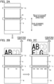
Figs. 2A-2C] Figs. 2A-2C are explanatory diagrams illustrating a manner that a printing pattern is printed on a printing medium using athermal head 5. - [
Fig. 3] Fig. 3 is a cross section of an ink ribbon R. - [
Figs. 4A-4C] Figs. 4A-4C are explanatory diagrams illustrating manners that afirst ink 71 and asecond ink 72 A are transferred to the printing medium M. - [
Fig. 5] Fig. 5 is a table illustrating a relationship between a first energy E1 and a second energy E2. - [
Fig. 6] Fig. 6 is a block diagram illustrating an electrical configuration of theprinting device 1. - [
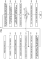
Fig. 7] Fig. 7 is a flowchart illustrating the printing process. - A
printing device 1 according to an embodiment of the present invention will be described while referring to the accompanied drawings. The accompanied drawings are just an example for illustrating technical features that may be employed in the present invention, but the present invention should not be limited only to the configuration illustrated in the drawings. - An overview of a
printing device 1 will be described with reference toFig. 1 . Theprinting device 1 is a thermal transfer printer that prints by heating an ink ribbon R to transfer ink onto a printing medium M. A roll MR of wound printing medium M is removably accommodated in theprinting device 1. Theprinting device 1 is provided with aroll support 21, aplaten 22, aribbon supply spool 31, a ribbon take-upspool 32, an inkribbon peeling member 33, athermal head 5, and the like. - The
roll support 21 rotatably supports the core of the roll MR. Theplaten 22 rotates when driven by amotor 44 described later (seeFig. 6 ) while in contact with the printing medium M. As a result, theplaten 22 draws the printing medium M off the roll MR and conveys the printing medium M toward adischarge unit 10 provided in a housing 11 of theprinting device 1. The conveying direction of the printing medium M corresponds to a sub-scanning direction. - The ink ribbon R is wound around the
ribbon supply spool 31. The ribbon take-upspool 32 draws unused ink ribbon R off theribbon supply spool 31 and takes up ink ribbon R that has been used for printing. The ink ribbon R runs from theribbon supply spool 31 along a conveying path. The conveying path along which the ink ribbon R is conveyed runs parallel to the conveying path of the printing medium M from theribbon supply spool 31 so that the ink ribbon R is in contact with the surface of the printing medium M on the side opposite theplaten 22 between theribbon supply spool 31 and the inkribbon peeling member 33, bends away from the printing medium M at the inkribbon peeling member 33 so that the ink ribbon R is in contact with the inkribbon peeling member 33, and extends to the ribbon take-upspool 32. The conveying direction of the ink ribbon R in the portion of the conveying path that runs parallel to the conveying path of the printing medium M is identical to the conveying direction of the printing medium M (i.e., the sub-scanning direction). Hereinafter, the conveying direction of the ink ribbon R in this portion of the conveying path that runs parallel to the printing medium M will be called the "conveying direction of the ink ribbon R." - The
thermal head 5 contacts the ink ribbon R drawn off theribbon supply spool 31 on the opposite side surface of the ink ribbon R from the printing medium M. The ink ribbon R and printing medium M are interposed between thethermal head 5 and theplaten 22. As illustrated inFig. 2A , thethermal head 5 is a line thermal head. Thethermal head 5 has a plurality ofheating elements 5A aligned in a main scanning direction, which is orthogonal to the sub-scanning direction. The gap between the twoheating elements 5A located on opposite ends of the plurality ofheating elements 5A in the main scanning direction is approximately the same as the length of the printing medium M in the main scanning direction. Thethermal head 5 heats the ink ribbon R by selectively heating the plurality ofheating elements 5A in contact with the ink ribbon R. - The
printing device 1 heats a plurality of theheating elements 5A in thethermal head 5 while conveying the printing medium M and ink ribbon R in the conveying direction. As a result, ink in the ink ribbon R melts and adheres to the printing medium M. After being heated by thethermal head 5, the ink ribbon R is peeled off the printing medium M at the inkribbon peeling member 33 positioned downstream of thethermal head 5 in the conveying direction, as illustrated inFigs. 2B and 2C . At this time, the ink adhered to the printing medium M is separated from the ink ribbon R and transferred to the printing medium M. Through this process, patterns are printed on the printing medium M. - The ink ribbon R will be described with reference to
Fig. 3 . The ink ribbon R has abase layer 70, afirst ink layer 71, anintermediate layer 73, and asecond ink layer 72. Thebase layer 70,first ink layer 71,intermediate layer 73, andsecond ink layer 72 are overlaid in this order. - The
base layer 70 contains abase material 70A made of PET. Thefirst ink layer 71 contains afirst ink 71A. Thesecond ink layer 72 contains asecond ink 72A that is different from thefirst ink 71A. Theintermediate layer 73 is interposed between thefirst ink layer 71 andsecond ink layer 72. - In the printing process performed by the
printing device 1, the printing medium M is overlaid on the ink ribbon R and faces thesecond ink layer 72, as illustrated inFig. 4A . Further, the plurality ofheating elements 5A in thethermal head 5 are arranged at positions where the plurality ofheating elements 5A faces thebase layer 70 of the ink ribbon R and is in contact with thebase layer 70. By selectively controlling the energy supplied to the plurality ofheating elements 5A in thethermal head 5, theprinting device 1 changes whether both thefirst ink 71A of thefirst ink layer 71 and thesecond ink 72A of thesecond ink layer 72 are transferred onto the printing medium M from the ink ribbon R (seeFig. 4B ) or thesecond ink 72A of thesecond ink layer 72 is transferred onto the printing medium M from the ink ribbon R (seeFig. 4C ). - For example, the
printing device 1 heats the ink ribbon R by supplying a first energy E1 to some of the plurality ofheating elements 5A in the thermal head 5 (hereinafter called the "first heating elements"). In this case, a bond strength C1 between thebase layer 70 andfirst ink layer 71 becomes lower than a bond strength C2 between thefirst ink layer 71 andsecond ink layer 72 and a bond strength C3 between thesecond ink layer 72 and printing medium M, as illustrated inFig. 4B . - When the ink
ribbon peeling member 33 peels the ink ribbon R off the printing medium M, the ink ribbon R breaks apart between thebase layer 70 andfirst ink layer 71 where the bond strength is relatively low. As a result, thefirst ink 71A of thefirst ink layer 71, theintermediate layer 73, and thesecond ink 72A of thesecond ink layer 72 are transferred to the printing medium M from the ink ribbon R, which has been heated by the first heating elements. In this case, thefirst ink 71A is exposed, producing a printing pattern on the printing medium M in the color of thefirst ink 71A. - As another example, the
printing device 1 heats the ink ribbon R by supplying a second energy E2 different from the first energy E1 to some of the plurality ofheating elements 5A in thethermal head 5 different from the first heating elements (hereinafter called the "second heating elements"). In this case, the bond strength C2 between thefirst ink layer 71 andsecond ink layer 72 becomes lower than the bond strength C1 between thebase layer 70 andfirst ink layer 71 and the bond strength C3 between thesecond ink layer 72 and printing medium M, as illustrated inFig. 4C . - As the ink
ribbon peeling member 33 peels the ink ribbon R off the printing medium M, the ink ribbon R breaks apart at theintermediate layer 73, i.e., between thefirst ink layer 71 andsecond ink layer 72 where the bond strength is relatively low. As a result, a portion of theintermediate layer 73 and thesecond ink 72A of thesecond ink layer 72 are transferred to the printing medium M from the ink ribbon R, which has been heated by the second heating elements. In this case, thesecond ink 72A is exposed through theintermediate layer 73, producing a printed pattern on the printing medium M in the color of thesecond ink 72A. - For example, the
printing device 1 supplies the first energy E1 tofirst heating elements 51 and supplies the second energy E2 tosecond heating elements 52 among the plurality ofheating elements 5A in thethermal head 5, as shown inFig. 2B . Through this process, the "AB" portion of the printing pattern "ABCD" aligned in the main scanning direction appears in the color of thefirst ink 71A while the "CD" portion appears in the color of thesecond ink 72A. As another example, theprinting device 1 supplies the first energy E1 tofirst heating elements second heating elements heating elements 5A in thethermal head 5, as illustrated inFig. 2C . Through this process, the "A" and "C" portions of the printing pattern "ABCD" aligned in the main scanning direction appear in the color of thefirst ink 71A, while the "B" and "D" portions appear in the color of thesecond ink 72A. By controlling the energy supplied to each of the plurality ofheating elements 5A in this way, theprinting device 1 can quickly print a printing pattern using inks of different types along the main scanning direction. - The
printing device 1 changes the respective supply conditions for the first energy E1 supplied to the first heating elements of thethermal head 5 and the second energy E2 supplied to the second heating elements according to the type of ink ribbon R being used. Below, first through fourth supply conditions will be described with reference toFig. 5 . - Under the first supply condition, the second energy E2 is greater than the first energy E1 (E1<E2). Further, the
printing device 1 supplies the first energy E1 to each of the first heating elements by supplying a first power P1 for a first time T1. The first energy E1, first power P1, and first time T1 satisfy the relationship "E1 = P1 × T1". On the other hand, theprinting device 1 supplies the second energy E2 to each of the second heating elements by supplying the first power P1 for a second time T2 longer than the first time T1 (T1<T2). The second energy E2, first power P1, and second time T2 satisfy the relationship "E2 = P1 × T2". - Under the second supply condition, the second energy E2 is greater than the first energy E1 (E1<E2), as with the first supply condition. Further, the
printing device 1 supplies the first energy E1 to each of the first heating elements by supplying a first power P1 for a first time T1. On the other hand, theprinting device 1 supplies the second energy E2 to each of the second heating elements by supplying a second power P2 greater than the first power P1 (P1<P2) for the first time T1. The second energy E2, second power P2, and first time T1 satisfy the relationship "E2 = P2 × T1". - Under the third supply conditions, the second energy E2 is smaller than the first energy E1 (E1>E2). Further, the
printing device 1 supplies the first energy E1 to each of the first heating elements by supplying a first power P1 for a first time T1. On the other hand, theprinting device 1 supplies the second energy E2 to each of the second heating elements by supplying the first power P1 for a second time T2 shorter than the first time T1 (T1>T2). - Under the fourth supply condition, the second energy E2 is smaller than the first energy E1 (E1>E2), as with the third supply condition. Further, the
printing device 1 supplies the first energy E1 to each of the first heating elements by supplying a first power P1 for a first time T1. On the other hand, theprinting device 1 supplies the second energy E2 to each of the second heating elements by supplying a second power P2 smaller than the first power P1 (P1>P2) for the first time T1. - As shown in
Fig. 6 , theprinting device 1 has aCPU 41, astorage 42, aninput unit 43,motors driver 46. - The
CPU 41 manages overall control of theprinting device 1. Thestorage 42 stores programs to be executed by theCPU 41, print data, and the like. Theinput unit 43 includes switches for configuring various settings on theprinting device 1. Themotor 44 is driven to rotate theplaten 22, whereby theplaten 22 conveys the printing medium M in the conveying direction. Themotor 45 is driven to rotate the ribbon take-upspool 32 so that the ribbon take-upspool 32 conveys the portion of the ink ribbon R that is in contact with the printing medium M, i.e., the portion of the ink ribbon R between theribbon supply spool 31 and the inkribbon peeling member 33, in the conveying direction. Thedriver 46 drives thethermal head 5 to selectively heat each of the plurality ofheating elements 5A. - A printing process will be described with reference to
Fig. 7 . When theinput unit 43 detects an instruction to begin printing a pattern, theCPU 41 starts the printing process by reading and executing a program stored in thestorage 42. - First, in S11 the
CPU 41 acquires the type of ink ribbon R to be used. Based on the acquired type of ink ribbon R, in S13 theCPU 41 sets one of the first through fourth supply conditions (seeFig. 5 ) as the condition for supplying energy to each of the plurality ofheating elements 5A in thethermal head 5. - In S15 the
CPU 41 begins conveying the ink ribbon R by driving themotor 45 to rotate the ribbon take-upspool 32. Next, in S17 theCPU 41 begins conveying the printing medium M by driving themotor 44 to rotate theplaten 22. - In S19 the
CPU 41 acquires, from thestorage 42, one line worth of print data that can be printed at one time by heat generated from the plurality ofheating elements 5A of thethermal head 5. In S21 theCPU 41 selects the heating elements to be used for printing the printing pattern in the color of thefirst ink 71A from among the plurality ofheating elements 5A based on the acquired line worth of print data. Subsequently, in S21 theCPU 41 sets the selected heating elements as the first heating elements. In S23 theCPU 41 also selects heating elements to be used for printing the printing pattern in the color of thesecond ink 72A from among the plurality ofheating elements 5A based on the acquired line worth of print data. Subsequently, in S23 theCPU 41 sets the selected heating elements as the second heating elements. In S25 theCPU 41 sets thoseheating elements 5A that have not been set as either the first heating elements or the second heating elements as third heating elements, which are not to generate heat. - In S27, based on the supply conditions set in the process of S13, the
CPU 41 determines conditions for the power P and time T when supplying one of the first energy E1 and second energy E2 to each of the plurality ofheating elements 5A. Subsequently, in S27 theCPU 41 supplies the first energy E1 to the first heating elements set in S21 and supplies the second energy E2 to the second heating elements set in S23. - In S29 the
CPU 41 then continues to convey the ink ribbon R with the ribbon take-upspool 32 and to convey the printing medium M with theplaten 22. As a result, the portion of the ink ribbon R heated by theheating elements 5A of thethermal head 5 is peeled off the printing medium M by the inkribbon peeling member 33. At this time, in S29 both thefirst ink 71A andsecond ink 72A are transferred to the printing medium M from the areas of the ink ribbon R heated by the first heating elements while only thesecond ink 72A is transferred to the printing medium M from areas of the ink ribbon R heated by the second heating elements. - In S31 the
CPU 41 determines whether all lines in the printing pattern have been printed. In a case where there remain unprinted lines among the lines configuring the printing pattern (S31: NO), theCPU 41 returns to S19. In S19 theCPU 41 acquires one line worth of print data for one of the unprinted lines from thestorage 42 and repeats the above process in S21-S29. However, in a case where theCPU 41 determines that all lines of the printing pattern have been printed (S31: YES), theCPU 41 advances to S33. - In S33 the
CPU 41 stops conveying the printing medium M by terminating the drive of themotor 44 to halt the rotation of theplaten 22. In S35 theCPU 41 stops conveying the ink ribbon R by terminating the drive of themotor 45 to halt the rotation of the ribbon take-upspool 32. TheCPU 41 then ends the printing process. - By using the
thermal head 5 to heat the ink ribbon R, which includes thefirst ink layer 71 and thesecond ink layer 72, theprinting device 1 can transfer both thefirst ink 71A andsecond ink 72A to the printing medium M and transfer thesecond ink 72A to the printing medium M. Accordingly, theprinting device 1 can perform multicolor printing using one ink ribbon R and onethermal head 5, thereby simplifying the device configuration. Moreover, by using a line thermal head as thethermal head 5, theprinting device 1 can print one line extending in the main scanning direction at a time. Accordingly, theprinting device 1 can print a pattern using the first ink and a pattern using the second ink within a single line. Hence, theprinting device 1 can achieve multicolor printing through a simplified configuration, making it possible to provide aprinting device 1 that is compact and easy to maintain. - Under the first and second supply conditions, the second energy E2 required for transferring the
second ink 72A to the printing medium M is higher than the first energy E1 required for transferring thefirst ink 71A andsecond ink 72A to the printing medium M (E1<E2). Thus, theprinting device 1 can perform multicolor printing by supplying energy to the plurality ofheating elements 5A in thethermal head 5 under these supply conditions. - Under the first supply condition, the
printing device 1 supplies the first energy E1 to the first heating elements by supplying a first power P1 for a first time T1 and supplies the second energy E2 to second heating elements by supplying the first power P1 for a second time T2, which is longer than the first time T1 (T1<T2). In this case, theprinting device 1 can produce the second energy E2 that is higher than the first energy E1 without modifying the power supplied to the plurality ofheating elements 5A. - Under the second supply conditions, the
printing device 1 supplies the first energy E1 to the first heating elements by supplying a first power P1 for a first time T1 and supplies the second energy E2 to the second heating elements by supplying a second power P2, which is greater than the first power P1 (P1<P2), for the first time T1. In this case, theprinting device 1 can produce a second energy E2 that is higher than the first energy E1 without modifying the time for which power is supplied to the plurality ofheating elements 5A. - Under the third and fourth supply conditions, the second energy E2 required for transferring the
second ink 72A to the printing medium M is lower than the first energy E1 required for transferring both thefirst ink 71A andsecond ink 72A to the printing medium M (E1>E2). Thus, theprinting device 1 can perform multicolor printing by supplying energy to the plurality ofheating elements 5A in thethermal head 5 under these supply conditions. - Under the third supply conditions, the
printing device 1 supplies the first energy E1 to the first heating elements by supplying a first power P1 for a first time T1 and supplies the second energy E2 to the second heating elements by supplying the first power P1 for a second time T2, which is shorter than the first time T1 (T1>T2). In this case, theprinting device 1 can produce the second energy E2 that is lower than the first energy E1 without modifying the power supplied to the plurality ofheating elements 5A. - Under the fourth supply conditions, the
printing device 1 supplies the first energy E1 to the first heating elements by supplying a first power P1 for a first time T1 and supplies the second energy E2 to the second heating elements by supplying a second power P2, which is smaller than the first power P1 (P1>P2), for the first time T1. In this case, theprinting device 1 can produce a second energy E2 that is lower than the first energy E1 without modifying the time for which power is supplied to the plurality ofheating elements 5A. - By supplying the first energy E1 to the first heating elements, the
printing device 1 can make the bond strength C1 between thebase layer 70 andfirst ink layer 71 the weakest so that the ink ribbon R breaks apart between thebase layer 70 and thefirst ink layer 71, allowing thefirst ink 71A andsecond ink 72A to be transferred onto the printing medium M. Further, by supplying the second energy E2 to the second heating elements, theprinting device 1 can make the bond strength C2 between thefirst ink layer 71 andsecond ink layer 72 the weakest so that theintermediate layer 73 therebetween breaks apart, enabling thesecond ink layer 72 to be transferred onto the printing medium M alone. - The present invention may be modified in various ways and is not limited to the embodiment described above. A cartridge accommodating the ink ribbon R and printing medium M may be detachably mounted in the
printing device 1. The ink ribbon R and printing medium M may be conveyed by a common conveying mechanism. Theprinting device 1 may move thethermal head 5 in the sub-scanning direction relative to the printing medium M and ink ribbon R. The user may set the energy supply condition through theinput unit 43. Alternatively, theprinting device 1 may select one of the first through fourth supply conditions according to the ambient temperature, type of printing medium M, and the like. - The ink ribbon R need not possess the
intermediate layer 73. In this case, thefirst ink layer 71 andsecond ink layer 72 may be in contact with each other. A welding layer including a welding material may be interposed between thebase layer 70 and thefirst ink layer 71. The bond strength between thebase layer 70 and thefirst ink layer 71 may be adjusted by the welding layer. A backing layer may be provided on the opposite side surface of thebase layer 70 from thefirst ink layer 71. Further, an adhesive layer may be provided on thesecond ink layer 72 on at least one of thefirst ink layer 71 side and the opposite side. - Energy may be supplied to the plurality of
heating elements 5A by continuously supplying a prescribed power P (the first power P1 or second power P2) for the prescribed time T (the first time T1 or second time T2) or may be supplied according to a different method. For example, the prescribed power P may be supplied intermittently to the plurality ofheating elements 5A. In this case, the prescribed time T is the total supply time of the intermittent power supply. The period for these intermittent supply of power P may be constant or not constant. - Each of the plurality of
heating elements 5A may be configured with variable resistance. Theprinting device 1 may adjust the power supplied to the plurality ofheating elements 5A by individually adjusting the resistance value of each of the plurality ofheating elements 5A. - The ribbon take-up
spool 32 is an example of the first conveying member of the present invention. Theplaten 22 is an example of the second conveying member of the present invention. Thethermal head 5 is an example of the line thermal head of the present invention. The inkribbon peeling member 33 is an example of the transfer member of the present invention. TheCPU 41 is an example of the processor of the present invention. TheCPU 41 performing the process of S27 is an example of the processor performing the first heating operation of the present invention and an example of the processor performing the second heating operation of the present invention. The process of S15 is an example the first conveying step of the present invention. The process of S17 is an example of the second conveying step of the present invention. The process of S27 is an example of the heating step, the first heating step, the second heating step of the present invention. The process of S29 is an example of the transferring step of the present invention. -
- 1: printing device
- 5: thermal head
- 5A:
heating element 5A - 22: platen
- 32: ribbon take-up
spool 32 - 33: ink ribbon peeling member
- 41: CPU
- 70: base layer
- 70A:
base material 70A - 71: first ink layer
- 71A: first ink
- 72: second ink layer
- 72A: second ink
- M: printing medium
Claims (9)
- A printing device comprising:a first conveying member configured to convey an ink ribbon in a sub-scanning direction, the ink ribbon including a base layer, a first ink layer having a first ink, and a second ink layer having a second ink different from the first ink, wherein the base layer, the first ink layer, and the second ink layer are overlaid in this order;a second conveying member configured to convey, in the sub-scanning direction, a printing medium that is overlaid on the ink ribbon and faces the second ink layer;a line thermal head having a plurality of heating elements arranged in a main scanning direction orthogonal to the sub-scanning direction, wherein the plurality of heating elements is configured to be in contact with the ink ribbon from the base layer side to heat the ink ribbon while the ink ribbon is conveyed by the first conveying member;a transfer member positioned downstream of the line thermal head in the sub-scanning direction, the transfer member being configured to transfer both the first ink and the second ink from the ink ribbon onto the printing medium or transfer the second ink from the ink ribbon heated by the line thermal head onto the printing medium, by separating the ink ribbon conveyed by the first conveying member from the printing medium; anda processor configured to control the first conveying member, the second conveying member, the line thermal head, and the transfer member,wherein the processor is configured to perform:a first heating operation supplying a first energy to a first heating element to heat the ink ribbon, the first heating element being one of the plurality of heating elements; anda second heating operation supplying a second energy to a second heating element to heat the ink ribbon, the second energy being different from the first energy, the second heating element being one of the plurality of heating elements and different from the first heating element,wherein the transfer member transfers both the first ink and the second ink onto the printing medium from the ink ribbon heated through the first heating operation,wherein the transfer member transfers the second ink onto the printing medium from the ink ribbon heated through the second heating operation.
- The printing device according to claim 1, wherein the second energy is greater than the first energy.
- The printing device according to claim 2, wherein the first heating operation supplies the first energy to the first heating element by supplying a first power for a first time,
wherein the second heating operation supplies the second energy to the second heating element by supplying the first power for a second time longer than the first time. - The printing device according to claim 2, wherein the first heating operation supplies the first energy to the first heating element by supplying a first power for a first time,
wherein the second heating operation supplies the second energy to the second heating element by supplying a second power for the first time, the second power being greater than the first power. - The printing device according to claim 1, wherein the second energy is smaller than the first energy.
- The printing device according to claim 5, wherein the first heating operation supplies the first energy to the first heating element by supplying a first power for a first time,
wherein the second heating operation supplies the second energy to the second heating element by supplying the first power for a second time shorter than the first time. - The printing device according to claim 5, wherein the first heating operation supplies the first energy to the first heating element by supplying a first power for a first time,
wherein the second heating operation supplies the second energy to the second heating element by supplying a second power for the first time, the second power being smaller than the first power. - The printing device according to claim 1, wherein in a case where the first heating operation heats the ink ribbon, a bond strength between the base layer and the first ink layer becomes smaller than both a bond strength between the first ink layer and the second ink layer and a bond strength between the second ink layer and the printing medium,
wherein in a case where the second heating operation heats the ink ribbon, the bond strength between the first ink layer and the second ink layer becomes smaller than both the bond strength between the base layer and the first ink layer and the bond strength between the second ink layer and the printing medium. - A printing method comprising:a first conveying step of conveying an ink ribbon in a sub-scanning direction, the ink ribbon including a base layer, a first ink layer having a first ink, and a second ink layer having a second ink different from the first ink, wherein the base layer, the first ink layer, and the second ink layer are overlaid in this order;a second conveying step of conveying, in the sub-scanning direction, a printing medium that is overlaid on the ink ribbon and faces the second ink layer;a heating step of heating the ink ribbon with a plurality of heating elements in contact with the ink ribbon from the base layer side while the ink ribbon is conveyed in the first conveying step, the plurality of heating elements being included in a line thermal head and being arranged in a main scanning direction orthogonal to the sub-scanning direction; anda transferring step of transferring at least one of the first ink and the second ink from the ink ribbon heated by the line thermal head onto the printing medium by separating, from the printing medium, the ink ribbon that is conveyed to a position downstream of the line thermal head in the sub-scanning direction in the first conveying step,wherein the heating step includes:a first heating step of supplying a first energy to a first heating element to heat the ink ribbon, the first heating element being one of the plurality of heating elements; anda second heating step of supplying a second energy to a second heating element to heat the ink ribbon, the second energy being different from the first energy, the second heating element being one of the plurality of heating elements and different from the first heating element,wherein the transferring step transfers both the first ink and the second ink onto the printing medium from the ink ribbon heated through the first heating step,wherein the transferring step transfers the second ink onto the printing medium from the ink ribbon heated through the second heating step.
Applications Claiming Priority (2)
| Application Number | Priority Date | Filing Date | Title |
|---|---|---|---|
| JP2022073977A JP2023163219A (en) | 2022-04-28 | 2022-04-28 | Printing device and printing method |
| PCT/JP2023/016246 WO2023210624A1 (en) | 2022-04-28 | 2023-04-25 | Printing device and printing method |
Publications (2)
| Publication Number | Publication Date |
|---|---|
| EP4516517A1 true EP4516517A1 (en) | 2025-03-05 |
| EP4516517A4 EP4516517A4 (en) | 2026-05-13 |
Family
ID=88518963
Family Applications (1)
| Application Number | Title | Priority Date | Filing Date |
|---|---|---|---|
| EP23796364.0A Pending EP4516517A4 (en) | 2022-04-28 | 2023-04-25 | PRINTING DEVICE AND PRINTING PROCESS |
Country Status (5)
| Country | Link |
|---|---|
| US (1) | US20250042177A1 (en) |
| EP (1) | EP4516517A4 (en) |
| JP (1) | JP2023163219A (en) |
| CN (1) | CN119095728A (en) |
| WO (1) | WO2023210624A1 (en) |
Family Cites Families (23)
| Publication number | Priority date | Publication date | Assignee | Title |
|---|---|---|---|---|
| JPS59190867A (en) * | 1983-04-15 | 1984-10-29 | Toshiba Corp | Printer |
| JPS6144661A (en) * | 1984-08-09 | 1986-03-04 | Canon Inc | Thermal transfer recording device |
| JPS6262791A (en) * | 1985-09-14 | 1987-03-19 | Canon Inc | Thermal sensitive transfer material |
| US5175563A (en) * | 1986-02-03 | 1992-12-29 | Canon Kabushiki Kaisha | Image recording apparatus and ink sheet cassette usable in the image recording apparatus |
| JPS62178392A (en) * | 1986-02-03 | 1987-08-05 | Canon Inc | Method and device for thermal transfer recording |
| JP2556472B2 (en) * | 1986-03-24 | 1996-11-20 | キヤノン株式会社 | Recording device |
| JPS62181188A (en) * | 1986-02-06 | 1987-08-08 | Canon Inc | Thermal transfer recording method and heat generating member used therein |
| JPS62227788A (en) * | 1986-03-31 | 1987-10-06 | Alps Electric Co Ltd | Two-color recording method and thermal transfer medium |
| JPS63214481A (en) * | 1987-03-02 | 1988-09-07 | Canon Inc | Thermal transfer material |
| JPS6424769A (en) * | 1987-07-22 | 1989-01-26 | Canon Kk | Thermal recorder |
| JPH01275071A (en) * | 1988-04-28 | 1989-11-02 | Canon Inc | Thermal transfer recording method |
| JPH0222087A (en) * | 1988-07-11 | 1990-01-24 | Canon Inc | Thermal transfer recording apparatus |
| JPH02117847A (en) * | 1988-10-28 | 1990-05-02 | Seiko Epson Corp | thermal transfer printer |
| JPH07117251A (en) * | 1993-10-26 | 1995-05-09 | Nec Corp | Multicolor thermal recording device |
| JPH0811335A (en) * | 1994-06-30 | 1996-01-16 | Casio Comput Co Ltd | Printer |
| JPH08281995A (en) * | 1995-04-17 | 1996-10-29 | Fuji Xerox Co Ltd | Ink sheet, thermal transfer recording device, and halftone recording method |
| JP2000094843A (en) * | 1998-09-18 | 2000-04-04 | Dainippon Printing Co Ltd | Thermal transfer sheet, integrated thermal transfer sheet and recording method |
| JP2001047654A (en) * | 1999-08-09 | 2001-02-20 | Alps Electric Co Ltd | Thermal transfer recording method |
| JP2008213236A (en) * | 2007-03-01 | 2008-09-18 | Toshiba Tec Corp | Thermal transfer printer |
| JP5827479B2 (en) | 2011-03-23 | 2015-12-02 | サトーホールディングス株式会社 | Thermal transfer color printer |
| JP2013022797A (en) * | 2011-07-20 | 2013-02-04 | Sinfonia Technology Co Ltd | Thermal transfer printer |
| JP6045414B2 (en) * | 2013-03-22 | 2016-12-14 | 三菱電機株式会社 | Thermal printer |
| JP6387731B2 (en) * | 2014-08-01 | 2018-09-12 | セイコーエプソン株式会社 | Print medium unit and printing apparatus |
-
2022
- 2022-04-28 JP JP2022073977A patent/JP2023163219A/en active Pending
-
2023
- 2023-04-25 CN CN202380036544.0A patent/CN119095728A/en active Pending
- 2023-04-25 EP EP23796364.0A patent/EP4516517A4/en active Pending
- 2023-04-25 WO PCT/JP2023/016246 patent/WO2023210624A1/en not_active Ceased
-
2024
- 2024-10-25 US US18/926,887 patent/US20250042177A1/en active Pending
Also Published As
| Publication number | Publication date |
|---|---|
| JP2023163219A (en) | 2023-11-10 |
| CN119095728A (en) | 2024-12-06 |
| WO2023210624A1 (en) | 2023-11-02 |
| EP4516517A4 (en) | 2026-05-13 |
| US20250042177A1 (en) | 2025-02-06 |
Similar Documents
| Publication | Publication Date | Title |
|---|---|---|
| JP2023137427A (en) | Transfer medium manufacturing device and transfer medium | |
| JP5574116B2 (en) | Printing device | |
| US20250042177A1 (en) | Printing device including heating elements heating ink ribbon selectively using first energy and second energy | |
| JP5034179B2 (en) | Mountless label printer and cutting method of mountless label paper | |
| JP5526606B2 (en) | Printing device | |
| JP5743088B2 (en) | PRINT LABEL CREATION DEVICE, PRINT LABEL CREATION PROGRAM, AND PRINT LABEL CREATION METHOD | |
| JP2012200874A (en) | Thermal transfer type color printer | |
| JP2696998B2 (en) | Thermal transfer recording device | |
| JP6029849B2 (en) | Printer | |
| JP2013136189A (en) | Printer | |
| JP2011213014A (en) | Thermal printer | |
| JP6071204B2 (en) | Printer | |
| JP7261638B2 (en) | Printer, printer control method, and program | |
| JP2004017995A (en) | Label printer and printing paper | |
| JP2025001188A (en) | Printer, printing method, and printing system | |
| JP5749035B2 (en) | Sorting ink application unit and printer | |
| JP2002283477A (en) | Label printer | |
| JP6764307B2 (en) | Printer | |
| JP2002079700A (en) | Printer | |
| JP2002154249A (en) | Thermal transfer line printer | |
| JP2013159067A (en) | Medium supply device and printer | |
| JP2013132754A (en) | Thermal transfer color printer | |
| JP2001253103A (en) | Printer and printing method thereof | |
| JP2013154578A (en) | Printer | |
| JP2002283600A (en) | Printing device and printing system |
Legal Events
| Date | Code | Title | Description |
|---|---|---|---|
| STAA | Information on the status of an ep patent application or granted ep patent |
Free format text: STATUS: THE INTERNATIONAL PUBLICATION HAS BEEN MADE |
|
| PUAI | Public reference made under article 153(3) epc to a published international application that has entered the european phase |
Free format text: ORIGINAL CODE: 0009012 |
|
| STAA | Information on the status of an ep patent application or granted ep patent |
Free format text: STATUS: REQUEST FOR EXAMINATION WAS MADE |
|
| 17P | Request for examination filed |
Effective date: 20241114 |
|
| AK | Designated contracting states |
Kind code of ref document: A1 Designated state(s): AL AT BE BG CH CY CZ DE DK EE ES FI FR GB GR HR HU IE IS IT LI LT LU LV MC ME MK MT NL NO PL PT RO RS SE SI SK SM TR |
|
| P01 | Opt-out of the competence of the unified patent court (upc) registered |
Free format text: CASE NUMBER: APP_11581/2025 Effective date: 20250310 |
|
| DAV | Request for validation of the european patent (deleted) | ||
| DAX | Request for extension of the european patent (deleted) | ||
| A4 | Supplementary search report drawn up and despatched |
Effective date: 20260413 |
|
| RIC1 | Information provided on ipc code assigned before grant |
Ipc: B41J 2/325 20060101AFI20260407BHEP Ipc: B41J 31/00 20060101ALI20260407BHEP Ipc: B41J 2/355 20060101ALI20260407BHEP Ipc: B41J 33/14 20060101ALI20260407BHEP |