EP4516424A1 - Gas blowing-up nozzle and continuous casting method - Google Patents
Gas blowing-up nozzle and continuous casting method Download PDFInfo
- Publication number
- EP4516424A1 EP4516424A1 EP23811737.8A EP23811737A EP4516424A1 EP 4516424 A1 EP4516424 A1 EP 4516424A1 EP 23811737 A EP23811737 A EP 23811737A EP 4516424 A1 EP4516424 A1 EP 4516424A1
- Authority
- EP
- European Patent Office
- Prior art keywords
- gas
- metal case
- refractory
- blowing
- nozzle
- Prior art date
- Legal status (The legal status is an assumption and is not a legal conclusion. Google has not performed a legal analysis and makes no representation as to the accuracy of the status listed.)
- Pending
Links
Images



Classifications
-
- B—PERFORMING OPERATIONS; TRANSPORTING
- B22—CASTING; POWDER METALLURGY
- B22D—CASTING OF METALS; CASTING OF OTHER SUBSTANCES BY THE SAME PROCESSES OR DEVICES
- B22D11/00—Continuous casting of metals, i.e. casting in indefinite lengths
- B22D11/10—Supplying or treating molten metal
-
- B—PERFORMING OPERATIONS; TRANSPORTING
- B22—CASTING; POWDER METALLURGY
- B22D—CASTING OF METALS; CASTING OF OTHER SUBSTANCES BY THE SAME PROCESSES OR DEVICES
- B22D41/00—Casting melt-holding vessels, e.g. ladles, tundishes, cups or the like
- B22D41/50—Pouring-nozzles
- B22D41/58—Pouring-nozzles with gas injecting means
-
- B—PERFORMING OPERATIONS; TRANSPORTING
- B22—CASTING; POWDER METALLURGY
- B22D—CASTING OF METALS; CASTING OF OTHER SUBSTANCES BY THE SAME PROCESSES OR DEVICES
- B22D41/00—Casting melt-holding vessels, e.g. ladles, tundishes, cups or the like
- B22D41/50—Pouring-nozzles
- B22D41/502—Connection arrangements; Sealing means therefor
-
- B—PERFORMING OPERATIONS; TRANSPORTING
- B22—CASTING; POWDER METALLURGY
- B22D—CASTING OF METALS; CASTING OF OTHER SUBSTANCES BY THE SAME PROCESSES OR DEVICES
- B22D41/00—Casting melt-holding vessels, e.g. ladles, tundishes, cups or the like
- B22D41/50—Pouring-nozzles
- B22D41/52—Manufacturing or repairing thereof
- B22D41/54—Manufacturing or repairing thereof characterised by the materials used therefor
Definitions
- the present invention relates to a gas-blowing upper nozzle that is provided at the bottom of a tundish and used in hot working, and to a continuous casting method using this nozzle.
- One measure to prevent nozzle clogging is to blow in an inert gas through the nozzle and make the inclusions float and separate so as to prevent the inclusions from adhering to and clogging the nozzle.
- Gas blowing in continuous casting nozzles is usually performed in an upper nozzle installed in a tundish, a sliding plate, and an immersion nozzle connected under the sliding plate, or the like.
- a porous gas-permeable material or a ventilation hole penetrating a refractory is sometimes used.
- the nozzle is often composed of a refractory 1 combining a non-gas-permeable material 1A and a gas-permeable material 1B as shown in Fig. 4 (a) .
- An outer circumference of a gas-blowing upper nozzle 100 is kept gastight by a metal case 2.
- the inert gas is introduced through an inert-gas introduction pipe 6 installed at a lateral lower part of the gas-blowing upper nozzle 100.
- this inert gas is introduced to the part of an upper gas-permeable material 1B through a gas flow passage, i.e., a gas pool 5 provided between a refractory outer circumference of the non-gas-permeable material 1A and the metal case 2. Then, this inert gas is blown into a flow of molten steel flowing down a through-hole 11 of the gas-blowing upper nozzle 100. The rest of the inert gas is blown into the flow of molten steel flowing down the through-hole 11 of the gas-blowing upper nozzle 100 through a lower gas-permeable material 1B.
- a gas flow passage i.e., a gas pool 5 provided between a refractory outer circumference of the non-gas-permeable material 1A and the metal case 2.
- sealability between the refractory 1 and the metal case 2 provided on the outer circumference has been a conventional problem.
- the inert gas leaks through the outer circumference of the refractory 1 and leaks out into the molten steel from a bed part of the tundish.
- a sufficient amount of inert gas to be blown into the molten steel passing through the through-hole 11 of the gas-blowing upper nozzle 100 cannot be secured.
- a cast slab that has been cast in such a state falls outside the specifications.
- Fig. 4 (b) is an enlarged schematic view of part B indicated by the dash-double-dot line in Fig. 4 (a) , i.e., the periphery of an upper end part of the gas-blowing upper nozzle 100.
- Fig. 4 (b) shows a state where the upper end of the metal case 2 has opened due to thermal deformation (indicated by the arrow). As continuous casting is repeated, the metal case 2 of the upper nozzle reaches a high temperature and thermally expands due to heat transfer from the molten steel. In the process, the upper end of the metal case 2 opens away from the refractory 1 as indicated by the arrow by pushing an upper-nozzle setting mortar 10.
- Patent Literatures 1 and 2 use a thermally expandable mortar that fills the gap left between the metal case and the gas-permeable material due to thermal expansion of the metal case.
- the coefficient of thermal expansion is generally high in the metal case and low in the refractory. Due to heating during the use of the nozzle, expansion of the metal case becomes large compared with the outer circumference of the nozzle refractory, thus leaving a gap between the outer circumference of the nozzle refractory and the metal case, through which the gas leaks.
- these technologies use the expandable mortar to prevent a gas leak.
- Patent Literatures 3 and 4 inhibit thermal expansion of the metal case by increasing a restraining force.
- a flexible refractory sealing material is disposed on an outer circumferential part of the metal case to restrain the metal case from deforming due to thermal expansion by the refractory sealing material and thereby inhibit thermal deformation.
- spiral fins are attached to an outer circumferential part of the metal case to thereby enhance the restraining force on the metal case.
- Patent Literatures 1 and 2 even when the thermal expansion rate of the mortar between the metal case and the gas-permeable material is increased, the mortar is limited in its amount of thermal expansion. There is a problem that if the metal case expands beyond the amount of expansion of the mortar, a gas leak through the gap between the metal case and the refractory cannot be completely prevented. Another problem is that when a foamable material is used to increase the thermal expansion rate of the mortar as in Patent Literature 2, the density of the mortar itself decreases and its sealability decreases.
- the method of physically inhibiting the thermal expansion of the metal case by increasing the restraining force on the metal case as in the technologies disclosed in Patent Literatures 3 and 4 also have the following problems.
- the method of wrapping a flexible refractory seal around the outer circumference of the metal case as in Patent Literature 3 is expected to have a reducing effect on thermal deformation of the metal case for the part where the refractory sealing material is wrapped, but cannot restrict the thermal expansion at the other portions. Further, if the refractory seal is wrapped around the entire metal case, the adhesion between the upper nozzle and the surrounding square brick decreases, so that the upper nozzle shifts up and down, which may increase the risk of a steel leak. Thus, this method cannot be called adequate as a gas leak inhibiting method.
- a gas-blowing upper nozzle according to the present invention that advantageously solves the above-described problems includes a refractory (1) including a gas-permeable material (1B), and a metal case (2) surrounding an outer circumference of the refractory (1).
- This gas-blowing upper nozzle is characterized in that it has an upper-end metal case (3) that extends inward from an upper end part of the metal case (2), and that an upper end of a sealing mortar part (4) between the refractory (1) and the metal case (2) is covered by the upper-end metal case (3).
- a continuous casting method according to the present invention that advantageously solves the above-described problems is characterized in that any one of the above-described gas-blowing upper nozzles is installed at the bottom of a tundish, and that molten steel is poured from the tundish into a casting mold through the gas-blowing upper nozzle while an inert gas is blown into the gas-permeable material.
- the gas-blowing upper nozzle according to the present invention can offer the following advantages:
- the gas-blowing upper nozzle is formed by the refractory including the gas-permeable material and the metal case having the upper-end metal case. Even when a gap occurs at the joint between the refractory and the metal case due to thermal deformation of the metal case, the upper-end metal case that is disposed so as to conceal the joint at the top end of the upper nozzle serves to physically interrupt a gas leak path. Thus, a gas leak can be prevented.
- molten steel is poured from the tundish into the mold through this gas-blowing upper nozzle, so that continuous casting can be performed without a gas leak and a favorable quality of a cast slab can be maintained.
- Fig. 1 is a view showing a vertical section of a gas-blowing upper nozzle according to one embodiment of the present invention.
- a refractory 1 inside a gas-blowing upper nozzle 100 has a through-hole 11 through which molten steel flows along a rotational axis (symmetrical axis) CL, and has a shape of a hollow, thick-walled rotating body.
- the through-hole 11 flares out toward an upper part.
- the refractory 1 has a flat part at its top end (upper end).
- the refractory 1 is composed of a combination of a non-gas-permeable material 1A and a gas-permeable material 1B.
- the gas-permeable material 1B can be disposed at an arbitrary position. From the position where the gas-permeable material 1B is disposed, a gas can be blown into molten steel passing through the through-hole 11.
- the non-gas-permeable material 1A can also be disposed at an arbitrary position. In the case where gas blowing is to be performed separately from two upper and lower positions as in Fig. 1 , separate blowing can be performed by disposing the non-gas-permeable material 1A at a boundary portion of the gas-permeable material 1B. When there is no particular need for performing separate gas blowing, a structure in which the refractory 1 is entirely composed of the gas-permeable material 1B can be adopted without any problem.
- a supply path of an inert gas to the gas-permeable material 1B is configured as follows. First, the inert gas is introduced into the gas-blowing upper nozzle 100 through an inert-gas introduction pipe 6. Then, the inert gas reaches the gas-permeable material 1B by passing through a gas pool 5 provided between the refractory 1 and a substantially cylindrical metal case 2 covering an outer circumference of the refractory 1. While the gas pool 5 is provided between the refractory 1 and the metal case 2 in the example of Fig. 1 , it is also possible to form the gas pool 5 by providing a slit in the refractory 1. In this embodiment, however, the structure in which the gas pool 5 is provided between the refractory 1 and the metal case 2 as in Fig. 1 can reap the advantages of the embodiment more remarkably.
- the inert gas having reached the gas pool 5 needs to entirely pass through the gas-permeable material 1B and be blown into the molten steel. That the inert gas leaks to the outside of the gas-blowing upper nozzle 100 through a portion other than the gas-permeable material 1B is called a gas leak.
- a gas leak occurs, a sufficient amount of inert gas fails to be supplied to the molten steel inside the hollow part of the gas-blowing upper nozzle 100. Therefore, a sufficient improving effect on the purity of the molten steel cannot be achieved. This can result in quality problems with a cast slab that has been cast.
- a sealing mortar part 4 is disposed between the refractory 1 and the metal case 2. The sealing mortar part 4 fills the gap between the refractory 1 and the metal case 2 other than the gas pool 5. The sealing mortar part 4 serves to prevent the inert gas from leaking to the outside of the gas-blowing upper nozzle 100.
- Fig. 2 (a) shows a schematic view of the gas-blowing upper nozzle 100 of the embodiment as set inside a tundish.
- the circumference of the gas-blowing upper nozzle 100 is surrounded by a tundish iron shell 7, a square brick 8, and an upper-nozzle-top refractory 9.
- the gas-blowing upper nozzle 100 is restrained by each of the materials surrounding it.
- An upper-nozzle setting mortar 10 is disposed at a joint between the square brick 8 and the metal case 2 as a way to leave no gap.
- a restraining force on the gas-blowing upper nozzle 100 is secured by a bonding force among the square brick 8, the upper-nozzle setting mortar 10, and the metal case 2.
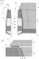
- Fig. 2 (b) shows a close-up of an upper end part of the gas-blowing upper nozzle 100 in part A of Fig. 2 (a) circled by the dash-double-dot line.
- the gas-blowing upper nozzle 100 has an upper-end metal case 3 that extends inward from an upper end part of the metal case 2.
- an upper end of the sealing mortar part 4 (joint part) between the refractory 1 and the metal case 2 is covered by the upper-end metal case 3.
- An outer circumference of the upper end of the metal case 2 and the upper-end metal case 3 may be coupled together by, for example, welding or caulking, or the metal case 2 and the upper-end metal case 3 may be integrally formed by draw forming etc.
- the upper-end metal case 3 have an annular shape along a flat part at the top end of the refractory 1.
- the upper-end metal case 3 is disposed at the upper end part of the gas-blowing upper nozzle 100 so as to create a state where the upper-end metal case 3 and the metal case 2 on the outer circumference of the upper nozzle are coupled together without a gap.
- a gas leak through the joint between the refractory 1 and the metal case 2 can be prevented. That is, even when thermal deformation as shown in Fig.
- the extension length of the upper-end metal case 3 be not smaller than the thickness of the joint between the metal case 2 and the square brick 8.
- the extension length of the upper-end metal case 3 be at a maximum within such a range that the upper-end metal case 3 is concealed by being held between the flat top end of the refractory 1 of the gas-blowing upper nozzle and the upper-nozzle-top refractory 9.
- the extension length of the upper-end metal case 3 is the length in a radial direction in a cylindrical coordinate system with the rotational axis CL as a central axis.
- the refractory 1 is, for example, a high-alumina material.
- the metal case 2 and the upper-end metal case 3 are made of metal, and, for example, carbon steel, alloy steel, stainless steel, cast steel, cast iron, titanium, and titanium alloy are suitably used.
- a high-alumina water-kneaded mortar that has been adjusted to appropriate consistency can be used.
- the thickness of the joint between the metal case (2) and the square brick (8) is about 1 to 5 mm.
- the range of being held between the flat top end of the refractory 1 of the gas-blowing upper nozzle 100 and the upper-nozzle-top refractory 9 is about 5 to 20 mm as a length in the radial direction from the rotational axis CL.
- the gas-blowing upper nozzle 100 of the above-described embodiment is disposed at the bottom of the tundish as shown in Fig. 2 . Then, the inert gas introduced through the inert-gas introduction pipe 6 is passed through the gas-permeable material 1B into the molten steel flowing down the through-hole 11. The molten steel inside the tundish is poured into a mold through a sliding nozzle and an immersion nozzle as necessary in addition to the gas-blowing upper nozzle 100.
- the gas-blowing upper nozzle 100 of the above-described embodiment By performing continuous casting using the gas-blowing upper nozzle 100 of the above-described embodiment, even when sequence casting is continuously performed, a gas leak attributable to deformation due to thermal expansion of the metal case 2 of the gas-blowing upper nozzle 100 can be prevented.
- the upper-end metal case 3 covers the top end of the gas-blowing upper nozzle 100 the top end need be covered such that the sealing mortar part 4 that is the joint between the refractory 1 and the metal case 2 is not exposed to the outside regardless of thermal deformation of the metal case 2. This configuration can prevent a gas leak.
- Fig. 5 shows a result of performing continuous casting with the gas-blowing upper nozzle of the embodiment shown in Fig. 1 and Fig. 2 and the conventional gas-blowing upper nozzle shown in Fig. 4 installed at the bottom of the tundish, and conducting an evaluation as to whether there was a gas leak based on a back pressure of the inert gas blown into the gas-blowing upper nozzles. Whether a gas leak has occurred can be determined by monitoring the back pressure of the inert gas being introduced into the gas-blowing upper nozzle.
- the back pressure of the inert gas is subjected to a resistant pressure that is the sum of a static pressure of the molten steel and permeation resistance of the gas-permeable material 1B, and this resistant pressure appears as a back pressure.
- a gas leak occurs, at least the permeation resistance of the gas-permeable material 1B does not occur, so that the back pressure decreases. Therefore, whether a gas leak had occurred was determined based on whether the back pressure had decreased, and the effects of the gas-blowing upper nozzle of the embodiment and the conventional gas-blowing upper nozzle were examined.
- a threshold value of the back pressure used for the determination depends on the casting facility and the operation rate, and therefore need be optimized for individual continuous casters.
- the determination was performed with a decrease in the back pressure of about 30% from the back pressure at normal times being called a decrease in the back pressure.
- the incidence rate of a decrease in the back pressure was 0.018.
- the gas-blowing upper nozzle and the continuous casting method of the present invention allow continuous casting to be performed while an inert gas having been blown in is blown into molten steel without a gas leak, so that a favorable quality of a cast slab can be maintained, which makes the present invention industrially useful.
Landscapes
- Engineering & Computer Science (AREA)
- Mechanical Engineering (AREA)
- Manufacturing & Machinery (AREA)
- Continuous Casting (AREA)
Abstract
Description
- The present invention relates to a gas-blowing upper nozzle that is provided at the bottom of a tundish and used in hot working, and to a continuous casting method using this nozzle.
- In conventional continuous casting of molten steel, clogging of a gas-blowing upper nozzle being used often occurs as inclusions, such as alumina (Al2O3), in molten steel adhere to and accumulate on the inner wall of the nozzle. When nozzle clogging occurs, the clogging substance comes off while the molten steel is being poured and gets mixed into the cast slab, or a non-uniform flow of the molten steel inside the nozzle occurs due to the clogging, thus leading to troubles related to the quality of the cast slab.
- One measure to prevent nozzle clogging is to blow in an inert gas through the nozzle and make the inclusions float and separate so as to prevent the inclusions from adhering to and clogging the nozzle. Gas blowing in continuous casting nozzles is usually performed in an upper nozzle installed in a tundish, a sliding plate, and an immersion nozzle connected under the sliding plate, or the like.
- For gas blowing in a gas-blowing upper nozzle, a porous gas-permeable material or a ventilation hole penetrating a refractory is sometimes used. In the case where a porous gas-permeable material is used, the nozzle is often composed of a refractory 1 combining a non-gas-
permeable material 1A and a gas-permeable material 1B as shown inFig. 4 (a) . An outer circumference of a gas-blowingupper nozzle 100 is kept gastight by ametal case 2. The inert gas is introduced through an inert-gas introduction pipe 6 installed at a lateral lower part of the gas-blowingupper nozzle 100. Part of this inert gas is introduced to the part of an upper gas-permeable material 1B through a gas flow passage, i.e., agas pool 5 provided between a refractory outer circumference of the non-gas-permeable material 1A and themetal case 2. Then, this inert gas is blown into a flow of molten steel flowing down a through-hole 11 of the gas-blowingupper nozzle 100. The rest of the inert gas is blown into the flow of molten steel flowing down the through-hole 11 of the gas-blowingupper nozzle 100 through a lower gas-permeable material 1B. Here, it is feared that a predetermined amount of inert gas may fail to be blown into the flow of molten steel flowing down the inside of the gas-blowing upper nozzle as the gas leaks through the gap between the outer circumference of the refractory 1 and themetal case 2 of the gas-blowingupper nozzle 100. Therefore, the refractory outer circumference of the non-gas-permeable material 1A and themetal case 2 are bonded together by a sealingmortar part 4 or the like to prevent a gas leak. - On the other hand, sealability between the refractory 1 and the
metal case 2 provided on the outer circumference has been a conventional problem. For example, if sealing between the refractory 1 and themetal case 2 is interrupted, the inert gas leaks through the outer circumference of therefractory 1 and leaks out into the molten steel from a bed part of the tundish. As a result, a sufficient amount of inert gas to be blown into the molten steel passing through the through-hole 11 of the gas-blowingupper nozzle 100 cannot be secured. A cast slab that has been cast in such a state falls outside the specifications. -
Fig. 4 (b) is an enlarged schematic view of part B indicated by the dash-double-dot line inFig. 4 (a) , i.e., the periphery of an upper end part of the gas-blowingupper nozzle 100.Fig. 4 (b) shows a state where the upper end of themetal case 2 has opened due to thermal deformation (indicated by the arrow). As continuous casting is repeated, themetal case 2 of the upper nozzle reaches a high temperature and thermally expands due to heat transfer from the molten steel. In the process, the upper end of themetal case 2 opens away from therefractory 1 as indicated by the arrow by pushing an upper-nozzle setting mortar 10. When themetal case 2 deforms in this way, a gap is left between the sealingmortar part 4 and themetal case 2. A gas leak is likely to occur through this gap. The cause of the phenomenon of an inert gas leak is that, as a gap is left between themetal case 2 and therefractory 1 as described above, the sealability of the sealingmortar part 4 decreases and a leak path is formed. Whether a gas leak has occurred can be grasped by detecting a change in the pressure (back pressure) of gas blowing. The back pressure decreases when a gas leak occurs. Therefore, in the case where gas blowing is performed during continuous casting, a system is established that monitors the back pressure of the gas being blown in and determines that there is an abnormality when the back pressure has decreased. - To prevent such a gas leak as described above, various improvements have been hitherto made. For example, the technologies disclosed in
Patent Literatures - Further, the technologies disclosed in
Patent Literatures Patent Literature 3, a flexible refractory sealing material is disposed on an outer circumferential part of the metal case to restrain the metal case from deforming due to thermal expansion by the refractory sealing material and thereby inhibit thermal deformation. InPatent Literature 4, spiral fins are attached to an outer circumferential part of the metal case to thereby enhance the restraining force on the metal case. -
- Patent Literature 1:
Japanese Patent Laid-Open No. 2011-256079 - Patent Literature 2:
Japanese Patent Laid-Open No. 2006-175482 - Patent Literature 3:
Japanese Patent Laid-Open No. 2016-36811 - Patent Literature 4:
Japanese Patent Laid-Open No. 2017-94386 - However, the above-described conventional technologies have the following problems.
- In the technologies disclosed in
Patent Literatures Patent Literature 2, the density of the mortar itself decreases and its sealability decreases. - The method of physically inhibiting the thermal expansion of the metal case by increasing the restraining force on the metal case as in the technologies disclosed in
Patent Literatures Patent Literature 3 is expected to have a reducing effect on thermal deformation of the metal case for the part where the refractory sealing material is wrapped, but cannot restrict the thermal expansion at the other portions. Further, if the refractory seal is wrapped around the entire metal case, the adhesion between the upper nozzle and the surrounding square brick decreases, so that the upper nozzle shifts up and down, which may increase the risk of a steel leak. Thus, this method cannot be called adequate as a gas leak inhibiting method. The method of installing fins on the outer circumference of the metal case as inPatent Literature 4 can be expected to have a reducing effect on thermal deformation of the entire metal case. However, if the fins have such dimensions as to come into contact with the square brick during the work of setting the upper nozzle inside the surrounding square brick, the fins may cause damage to the square brick itself. Thus, there is a problem that the work of inserting the upper nozzle becomes difficult. On the other hand, if the outside diameter of the fins is designed to be smaller than the inside diameter of the square brick, this raises a problem that the strength increasing effect is so small that thermal expansion of the metal case cannot be completely inhibited. - The present invention aims to solve the above-described conventional problems and provide a technology that can prevent the occurrence of a gas leak when blowing in an inert gas through a gas-blowing upper nozzle during continuous casting of molten steel. Here, a gas leak refers to an outflow of an inert gas to a part other than the gas-permeable material through the gap between the refractory and the metal case provided on the outer circumference of the gas-blowing upper nozzle.
- A gas-blowing upper nozzle according to the present invention that advantageously solves the above-described problems includes a refractory (1) including a gas-permeable material (1B), and a metal case (2) surrounding an outer circumference of the refractory (1). This gas-blowing upper nozzle is characterized in that it has an upper-end metal case (3) that extends inward from an upper end part of the metal case (2), and that an upper end of a sealing mortar part (4) between the refractory (1) and the metal case (2) is covered by the upper-end metal case (3).
- In the gas-blowing upper nozzle according to the present invention, the following could be more preferable solutions:
- (a) that an extension length of the upper-end metal case (3) is not smaller than a thickness of a joint between the metal case (2) and a square brick (8); and
- (b) that a leading end of the extending upper-end metal case (3) is within such a range as to be concealed by being held between a flat top end of the refractory (1) and an upper-nozzle-top refractory (9).
- A continuous casting method according to the present invention that advantageously solves the above-described problems is characterized in that any one of the above-described gas-blowing upper nozzles is installed at the bottom of a tundish, and that molten steel is poured from the tundish into a casting mold through the gas-blowing upper nozzle while an inert gas is blown into the gas-permeable material.
- Configured as has been described above, the gas-blowing upper nozzle according to the present invention can offer the following advantages: The gas-blowing upper nozzle is formed by the refractory including the gas-permeable material and the metal case having the upper-end metal case. Even when a gap occurs at the joint between the refractory and the metal case due to thermal deformation of the metal case, the upper-end metal case that is disposed so as to conceal the joint at the top end of the upper nozzle serves to physically interrupt a gas leak path. Thus, a gas leak can be prevented. In the continuous casting method according to the present invention, molten steel is poured from the tundish into the mold through this gas-blowing upper nozzle, so that continuous casting can be performed without a gas leak and a favorable quality of a cast slab can be maintained.
-
- [
Fig. 1] Fig. 1 is a vertical sectional view of a gas-blowing upper nozzle according to one embodiment of the present invention. - [
Fig. 2] Fig. 2 (a) is a schematic sectional view of the gas-blowing upper nozzle of the embodiment as installed in a tundish, andFig. 2 (b) is a partially enlarged sectional view of part A ofFig. 2 (a) . - [
Fig. 3] Fig. 3 is a conceptual sectional view showing a state where a metal case of the gas-blowing upper nozzle of the embodiment has thermally expanded. - [
Fig. 4] Fig. 4 (a) is a schematic sectional view of a conventional gas-blowing upper nozzle as installed in a tundish, andFig. 4 (b) is a partially enlarged sectional view of part B ofFig. 4 (a) and is a conceptual sectional view showing a state where a metal case has thermally expanded. - [
Fig. 5] Fig. 5 is a graph evaluating a status of a gas leak when continuous casting is performed using the gas-blowing upper nozzle of the embodiment, as compared with a conventional example. - An embodiment of the present invention will be specifically described below. Each drawing is schematic and may differ from the reality. The following embodiment presents examples of a device and a method for embodying the technical idea of the present invention, and is not intended to restrict the configuration to the one to be described below. Thus, various changes can be made to the technical idea of the present invention within the technical scope described in the claims.
-
Fig. 1 is a view showing a vertical section of a gas-blowing upper nozzle according to one embodiment of the present invention. A refractory 1 inside a gas-blowingupper nozzle 100 has a through-hole 11 through which molten steel flows along a rotational axis (symmetrical axis) CL, and has a shape of a hollow, thick-walled rotating body. The through-hole 11 flares out toward an upper part. The refractory 1 has a flat part at its top end (upper end). In the example ofFig. 1 , the refractory 1 is composed of a combination of a non-gas-permeable material 1A and a gas-permeable material 1B. The gas-permeable material 1B can be disposed at an arbitrary position. From the position where the gas-permeable material 1B is disposed, a gas can be blown into molten steel passing through the through-hole 11. The non-gas-permeable material 1A can also be disposed at an arbitrary position. In the case where gas blowing is to be performed separately from two upper and lower positions as inFig. 1 , separate blowing can be performed by disposing the non-gas-permeable material 1A at a boundary portion of the gas-permeable material 1B. When there is no particular need for performing separate gas blowing, a structure in which the refractory 1 is entirely composed of the gas-permeable material 1B can be adopted without any problem. - A supply path of an inert gas to the gas-
permeable material 1B is configured as follows. First, the inert gas is introduced into the gas-blowingupper nozzle 100 through an inert-gas introduction pipe 6. Then, the inert gas reaches the gas-permeable material 1B by passing through agas pool 5 provided between the refractory 1 and a substantiallycylindrical metal case 2 covering an outer circumference of the refractory 1. While thegas pool 5 is provided between the refractory 1 and themetal case 2 in the example ofFig. 1 , it is also possible to form thegas pool 5 by providing a slit in the refractory 1. In this embodiment, however, the structure in which thegas pool 5 is provided between the refractory 1 and themetal case 2 as inFig. 1 can reap the advantages of the embodiment more remarkably. - The inert gas having reached the
gas pool 5 needs to entirely pass through the gas-permeable material 1B and be blown into the molten steel. That the inert gas leaks to the outside of the gas-blowingupper nozzle 100 through a portion other than the gas-permeable material 1B is called a gas leak. When a gas leak occurs, a sufficient amount of inert gas fails to be supplied to the molten steel inside the hollow part of the gas-blowingupper nozzle 100. Therefore, a sufficient improving effect on the purity of the molten steel cannot be achieved. This can result in quality problems with a cast slab that has been cast. To prevent such a gas leak, a sealingmortar part 4 is disposed between the refractory 1 and themetal case 2. The sealingmortar part 4 fills the gap between the refractory 1 and themetal case 2 other than thegas pool 5. The sealingmortar part 4 serves to prevent the inert gas from leaking to the outside of the gas-blowingupper nozzle 100. -
Fig. 2 (a) shows a schematic view of the gas-blowingupper nozzle 100 of the embodiment as set inside a tundish. The circumference of the gas-blowingupper nozzle 100 is surrounded by atundish iron shell 7, asquare brick 8, and an upper-nozzle-top refractory 9. The gas-blowingupper nozzle 100 is restrained by each of the materials surrounding it. An upper-nozzle setting mortar 10 is disposed at a joint between thesquare brick 8 and themetal case 2 as a way to leave no gap. A restraining force on the gas-blowingupper nozzle 100 is secured by a bonding force among thesquare brick 8, the upper-nozzle setting mortar 10, and themetal case 2. -
Fig. 2 (b) shows a close-up of an upper end part of the gas-blowingupper nozzle 100 in part A ofFig. 2 (a) circled by the dash-double-dot line. In this embodiment, the gas-blowingupper nozzle 100 has an upper-end metal case 3 that extends inward from an upper end part of themetal case 2. In this configuration, an upper end of the sealing mortar part 4 (joint part) between the refractory 1 and themetal case 2 is covered by the upper-end metal case 3. An outer circumference of the upper end of themetal case 2 and the upper-end metal case 3 may be coupled together by, for example, welding or caulking, or themetal case 2 and the upper-end metal case 3 may be integrally formed by draw forming etc. It is preferable that the upper-end metal case 3 have an annular shape along a flat part at the top end of the refractory 1. The upper-end metal case 3 is disposed at the upper end part of the gas-blowingupper nozzle 100 so as to create a state where the upper-end metal case 3 and themetal case 2 on the outer circumference of the upper nozzle are coupled together without a gap. Thus, even when themetal case 2 undergoes thermal deformation, a gas leak through the joint between the refractory 1 and themetal case 2 can be prevented. That is, even when thermal deformation as shown inFig. 3 (indicated by the arrow) occurs, a gas leak path formed at the joint between the refractory 1 and themetal case 2 is blocked by the upper-end metal case 3 and thesealing mortar part 4, and thus the gas leak path can be physically interrupted. In this case, the limit length to which themetal case 2 opens due to thermal deformation depends on the thickness of the joint between themetal case 2 and thesquare brick 8. Therefore, to provide a gas leak preventing effect even when themetal case 2 undergoes maximum thermal deformation, it is preferable that the extension length of the upper-end metal case 3 be not smaller than the thickness of the joint between themetal case 2 and thesquare brick 8. When coming into direct contact with the molten steel, the upper-end metal case 3 melts and can no longer retain its shape. Therefore, it is preferable that the extension length of the upper-end metal case 3 be at a maximum within such a range that the upper-end metal case 3 is concealed by being held between the flat top end of the refractory 1 of the gas-blowing upper nozzle and the upper-nozzle-top refractory 9. Here, the extension length of the upper-end metal case 3 is the length in a radial direction in a cylindrical coordinate system with the rotational axis CL as a central axis. - The refractory 1 is, for example, a high-alumina material. The
metal case 2 and the upper-end metal case 3 are made of metal, and, for example, carbon steel, alloy steel, stainless steel, cast steel, cast iron, titanium, and titanium alloy are suitably used. For thesealing mortar part 4 and the upper-nozzle setting mortar 10, for example, a high-alumina water-kneaded mortar that has been adjusted to appropriate consistency can be used. The thickness of the joint between the metal case (2) and the square brick (8) is about 1 to 5 mm. The range of being held between the flat top end of the refractory 1 of the gas-blowingupper nozzle 100 and the upper-nozzle-top refractory 9 is about 5 to 20 mm as a length in the radial direction from the rotational axis CL. - In a continuous casting method as another embodiment of the present invention, the gas-blowing
upper nozzle 100 of the above-described embodiment is disposed at the bottom of the tundish as shown inFig. 2 . Then, the inert gas introduced through the inert-gas introduction pipe 6 is passed through the gas-permeable material 1B into the molten steel flowing down the through-hole 11. The molten steel inside the tundish is poured into a mold through a sliding nozzle and an immersion nozzle as necessary in addition to the gas-blowingupper nozzle 100. By performing continuous casting using the gas-blowingupper nozzle 100 of the above-described embodiment, even when sequence casting is continuously performed, a gas leak attributable to deformation due to thermal expansion of themetal case 2 of the gas-blowingupper nozzle 100 can be prevented. As for the range that the upper-end metal case 3 covers the top end of the gas-blowingupper nozzle 100, the top end need be covered such that the sealingmortar part 4 that is the joint between the refractory 1 and themetal case 2 is not exposed to the outside regardless of thermal deformation of themetal case 2. This configuration can prevent a gas leak. -
Fig. 5 shows a result of performing continuous casting with the gas-blowing upper nozzle of the embodiment shown inFig. 1 andFig. 2 and the conventional gas-blowing upper nozzle shown inFig. 4 installed at the bottom of the tundish, and conducting an evaluation as to whether there was a gas leak based on a back pressure of the inert gas blown into the gas-blowing upper nozzles. Whether a gas leak has occurred can be determined by monitoring the back pressure of the inert gas being introduced into the gas-blowing upper nozzle. Specifically, when the inert gas is normally blown into the molten steel through the gas-permeable material 1B, the back pressure of the inert gas is subjected to a resistant pressure that is the sum of a static pressure of the molten steel and permeation resistance of the gas-permeable material 1B, and this resistant pressure appears as a back pressure. However, when a gas leak occurs, at least the permeation resistance of the gas-permeable material 1B does not occur, so that the back pressure decreases. Therefore, whether a gas leak had occurred was determined based on whether the back pressure had decreased, and the effects of the gas-blowing upper nozzle of the embodiment and the conventional gas-blowing upper nozzle were examined. - Here, a threshold value of the back pressure used for the determination depends on the casting facility and the operation rate, and therefore need be optimized for individual continuous casters. In the continuous caster used for the determination this time, the determination was performed with a decrease in the back pressure of about 30% from the back pressure at normal times being called a decrease in the back pressure. As shown in
Fig. 5 , when the conventional gas-blowing upper nozzle (conventional example: N = 1012) was used, the incidence rate of a decrease in the back pressure was 0.018. By contrast, adopting the embodiment (example of present invention: N = 107) successfully prevented a decrease in the back pressure, i.e., the occurrence of a gas leak. - The gas-blowing upper nozzle and the continuous casting method of the present invention allow continuous casting to be performed while an inert gas having been blown in is blown into molten steel without a gas leak, so that a favorable quality of a cast slab can be maintained, which makes the present invention industrially useful.
-
- 100
- Gas-blowing upper nozzle (upper nozzle)
- 1
- Refractory
- 1A
- Non-gas-permeable material
- 1B
- Gas-permeable material
- 2
- Metal case
- 3
- Upper-end metal case
- 4
- Sealing mortar part
- 5
- Gas pool (gas flow passage)
- 6
- Inert-gas introduction pipe
- 7
- Tundish iron shell
- 8
- Square brick
- 9
- Upper-nozzle-top refractory
- 10
- Upper-nozzle setting mortar
- 11
- Through-hole
- CL
- Rotational axis (symmetrical axis)
Claims (4)
- A gas-blowing upper nozzle comprising:a refractory (1) including a gas-permeable material (1B); anda metal case (2) surrounding an outer circumference of the refractory (1), characterized in that:the gas-blowing upper nozzle has an upper-end metal case (3) that extends inward from an upper end part of the metal case (2); andan upper end of a sealing mortar part (4) between the refractory (1) and the metal case (2) is covered by the upper-end metal case (3).
- The gas-blowing upper nozzle according to claim 1, wherein an extension length of the upper-end metal case (3) is not smaller than a thickness of a joint between the metal case (2) and a square brick (8).
- The gas-blowing upper nozzle according to claim 2, wherein a leading end of the extending upper-end metal case (3) is within such a range as to be concealed by being held between a flat top end of the refractory (1) and an upper-nozzle-top refractory (9).
- A continuous casting method characterized in that the gas-blowing upper nozzle according to any one of claims 1 to 3 is installed at a bottom of a tundish, and that molten steel is poured from the tundish into a mold through the gas-blowing upper nozzle while an inert gas is blown into the gas-permeable material.
Applications Claiming Priority (2)
| Application Number | Priority Date | Filing Date | Title |
|---|---|---|---|
| JP2022086565A JP7700732B2 (en) | 2022-05-27 | 2022-05-27 | Gas blowing nozzle and continuous casting method |
| PCT/JP2023/018626 WO2023228864A1 (en) | 2022-05-27 | 2023-05-18 | Gas blowing-up nozzle and continuous casting method |
Publications (2)
| Publication Number | Publication Date |
|---|---|
| EP4516424A1 true EP4516424A1 (en) | 2025-03-05 |
| EP4516424A4 EP4516424A4 (en) | 2025-12-03 |
Family
ID=88919288
Family Applications (1)
| Application Number | Title | Priority Date | Filing Date |
|---|---|---|---|
| EP23811737.8A Pending EP4516424A4 (en) | 2022-05-27 | 2023-05-18 | GAS INFLATION NOZZLE AND CONTINUOUS CASTING PROCESS |
Country Status (6)
| Country | Link |
|---|---|
| EP (1) | EP4516424A4 (en) |
| JP (1) | JP7700732B2 (en) |
| KR (1) | KR20240166006A (en) |
| CN (1) | CN119110756A (en) |
| TW (2) | TWI896977B (en) |
| WO (1) | WO2023228864A1 (en) |
Family Cites Families (11)
| Publication number | Priority date | Publication date | Assignee | Title |
|---|---|---|---|---|
| JPH0184859U (en) * | 1987-11-27 | 1989-06-06 | ||
| ES2101697T3 (en) * | 1989-05-01 | 1997-07-16 | Vesuvius Crucible Co | PERMEABLE MAGNESIUM OXIDE NOZZLE. |
| JPH0342351U (en) * | 1989-08-29 | 1991-04-22 | ||
| JPH04100663A (en) * | 1990-08-20 | 1992-04-02 | Akechi Ceramics Kk | Nozzle for continuous casting |
| JP2001334360A (en) | 2000-05-22 | 2001-12-04 | Shinagawa Refract Co Ltd | Flow regulating nozzle and method for manufacturing the same |
| PL375692A1 (en) * | 2002-09-03 | 2005-12-12 | Vesuvius Crucible Company | Gas purged nozzle |
| JP4359234B2 (en) | 2004-12-22 | 2009-11-04 | 黒崎播磨株式会社 | Fireproof sealing material for gas blowing nozzle |
| CN102630191A (en) * | 2009-11-18 | 2012-08-08 | 东京窑业株式会社 | High-temperature assembly, method for producing high-temperature assembly, and heat-resistant sealing agent |
| JP2011256079A (en) | 2010-06-10 | 2011-12-22 | Tokyo Yogyo Co Ltd | Heat resistant sealing agent, high temperature assembly, and method for manufacturing high temperature assembly |
| JP5910681B2 (en) | 2014-08-05 | 2016-04-27 | 品川リフラクトリーズ株式会社 | Gas blowing up nozzle Metal case restraining method and gas blowing up nozzle |
| JP2017094386A (en) | 2015-11-27 | 2017-06-01 | 株式会社神戸製鋼所 | Upper nozzle |
-
2022
- 2022-05-27 JP JP2022086565A patent/JP7700732B2/en active Active
-
2023
- 2023-05-18 WO PCT/JP2023/018626 patent/WO2023228864A1/en not_active Ceased
- 2023-05-18 CN CN202380035875.2A patent/CN119110756A/en active Pending
- 2023-05-18 KR KR1020247035290A patent/KR20240166006A/en active Pending
- 2023-05-18 EP EP23811737.8A patent/EP4516424A4/en active Pending
- 2023-05-24 TW TW112119339A patent/TWI896977B/en active
- 2023-05-24 TW TW114129893A patent/TW202545654A/en unknown
Also Published As
| Publication number | Publication date |
|---|---|
| TW202402422A (en) | 2024-01-16 |
| EP4516424A4 (en) | 2025-12-03 |
| JP2023173982A (en) | 2023-12-07 |
| TWI896977B (en) | 2025-09-11 |
| JP7700732B2 (en) | 2025-07-01 |
| WO2023228864A1 (en) | 2023-11-30 |
| CN119110756A (en) | 2024-12-10 |
| KR20240166006A (en) | 2024-11-25 |
| TW202545654A (en) | 2025-12-01 |
Similar Documents
| Publication | Publication Date | Title |
|---|---|---|
| US5186886A (en) | Composite nozzle assembly for conducting a flow of molten metal in an electromagnetic valve | |
| US5173242A (en) | Means and method for forming a sealed connection | |
| JP7700732B2 (en) | Gas blowing nozzle and continuous casting method | |
| US5191926A (en) | Device for slag-free pouring with continuous casting machines | |
| RU2849468C2 (en) | Upper nozzle for gas injection and continuous dispensing method | |
| JP7464825B2 (en) | Breakout detection device, method for monitoring breakouts, and method for continuous casting of metals | |
| JPH11207457A (en) | Upper nozzle for sliding gate | |
| JP7755156B2 (en) | Breakout detection device, continuous metal casting system, and continuous metal casting method | |
| JP2017094386A (en) | Upper nozzle | |
| JP2006508804A (en) | Refractory plate for nozzle insertion and / or removal equipment of casting equipment incorporating sliding plate type flow control device | |
| JP2020505578A (en) | Cooling plate for metallurgical furnace | |
| EP0128987A2 (en) | Tuyere and method for blowing gas into molten metal | |
| JP5697193B2 (en) | Nozzle for gas injection | |
| JPH1121617A (en) | Immersion tube in rh equipment having preventing structure to seal metal deformation | |
| JPH07228907A (en) | How to prevent water leakage from damaged tuyere | |
| JP2017127886A (en) | Soaking nozzle | |
| JPH07256415A (en) | Tundish upper nozzle | |
| JP3739559B2 (en) | Method for determining the service life of immersion nozzles for continuous casting | |
| KR100478819B1 (en) | A gasket for collector nozzle | |
| JPH101714A (en) | Immersion tube for treating molten metal | |
| KR200277277Y1 (en) | A gasket for collector nozzle | |
| JP2010159460A (en) | Lance pipe | |
| JP2012526659A (en) | Casting nozzle used in molten metal container | |
| JP3286190B2 (en) | Gas injection nozzle for molten metal furnace and its wear control method | |
| JP3739558B2 (en) | Method for determining the service life of long nozzles for continuous casting |
Legal Events
| Date | Code | Title | Description |
|---|---|---|---|
| STAA | Information on the status of an ep patent application or granted ep patent |
Free format text: STATUS: THE INTERNATIONAL PUBLICATION HAS BEEN MADE |
|
| PUAI | Public reference made under article 153(3) epc to a published international application that has entered the european phase |
Free format text: ORIGINAL CODE: 0009012 |
|
| STAA | Information on the status of an ep patent application or granted ep patent |
Free format text: STATUS: REQUEST FOR EXAMINATION WAS MADE |
|
| 17P | Request for examination filed |
Effective date: 20241127 |
|
| AK | Designated contracting states |
Kind code of ref document: A1 Designated state(s): AL AT BE BG CH CY CZ DE DK EE ES FI FR GB GR HR HU IE IS IT LI LT LU LV MC ME MK MT NL NO PL PT RO RS SE SI SK SM TR |
|
| DAV | Request for validation of the european patent (deleted) | ||
| DAX | Request for extension of the european patent (deleted) | ||
| A4 | Supplementary search report drawn up and despatched |
Effective date: 20251105 |
|
| RIC1 | Information provided on ipc code assigned before grant |
Ipc: B22D 11/10 20060101AFI20251030BHEP Ipc: B22D 41/58 20060101ALI20251030BHEP Ipc: B22D 41/50 20060101ALI20251030BHEP Ipc: B22D 41/54 20060101ALI20251030BHEP |