EP4516336A1 - Vorrichtung und verpackungssystem zum transport von medizinischen geräten - Google Patents
Vorrichtung und verpackungssystem zum transport von medizinischen geräten Download PDFInfo
- Publication number
- EP4516336A1 EP4516336A1 EP23306429.4A EP23306429A EP4516336A1 EP 4516336 A1 EP4516336 A1 EP 4516336A1 EP 23306429 A EP23306429 A EP 23306429A EP 4516336 A1 EP4516336 A1 EP 4516336A1
- Authority
- EP
- European Patent Office
- Prior art keywords
- plate
- projections
- edge
- sidewall
- lower edge
- Prior art date
- Legal status (The legal status is an assumption and is not a legal conclusion. Google has not performed a legal analysis and makes no representation as to the accuracy of the status listed.)
- Pending
Links
Images

Classifications
-
- A—HUMAN NECESSITIES
- A61—MEDICAL OR VETERINARY SCIENCE; HYGIENE
- A61M—DEVICES FOR INTRODUCING MEDIA INTO, OR ONTO, THE BODY; DEVICES FOR TRANSDUCING BODY MEDIA OR FOR TAKING MEDIA FROM THE BODY; DEVICES FOR PRODUCING OR ENDING SLEEP OR STUPOR
- A61M5/00—Devices for bringing media into the body in a subcutaneous, intra-vascular or intramuscular way; Accessories therefor, e.g. filling or cleaning devices, arm-rests
- A61M5/008—Racks for supporting syringes or needles
-
- A—HUMAN NECESSITIES
- A61—MEDICAL OR VETERINARY SCIENCE; HYGIENE
- A61M—DEVICES FOR INTRODUCING MEDIA INTO, OR ONTO, THE BODY; DEVICES FOR TRANSDUCING BODY MEDIA OR FOR TAKING MEDIA FROM THE BODY; DEVICES FOR PRODUCING OR ENDING SLEEP OR STUPOR
- A61M2207/00—Methods of manufacture, assembly or production
- A61M2207/10—Device therefor
Definitions
- the present disclosure relates generally to a device for transporting medical containers, such as syringes, and components thereof, such as stoppers, and an associated container in which the plate is received.
- Medical containers such as pre-fillable or prefilled syringes, vials, and ampoules, and components for use with these containers, such as stoppers, may be transported from one site to another site.
- medical containers may be transported from a manufacturing site to a site at which the medical containers may be filled with a medicinal fluid.
- the medical containers may be manufactured and filled at the same site and subsequently transported to a storage site in a sterile packaging.
- the medical containers may be supported by a holding device, which may be referred to as a nest.
- One or more holding devices may be disposed within a packaging having an opening allowing for placement of the holding devices therein and subsequently sealed by a sealing cover.
- the container may be referred to as a tub.
- the holding device may be susceptible to moving relative to the packaging during transportation. As a result of such movement during long-distance transport, the holding device rubs against an inner surface of the packaging and may wear away material of the packaging or of the holding device so as to create particles of the packaging material and/or the holding device material. Because the packaging is sealed by the sealing cover, the particles remain inside the packaging throughout the remainder of transportation and storage. Such particles may be dispersed within the packaging and thus disposed within or on the medical containers stored inside the packaging. When the medical containers arrive at the destination, the medical containers are intended to be in a ready-to-use condition.
- the syringes when the medical containers are pre-fillable syringes, the syringes are intended to be in a clean and sterile condition upon arrival at the filling site so that the syringes may be filled with medicinal fluid. If the particles of the packaging material and/or of the holding device material are dispersed within or on the syringes, the syringes are not in a ready-to-use condition and must be cleaned prior to filling in order to avoid contamination of the medicinal fluid with which the medical containers will be filled. Accordingly, there is a need for a packaging solution that would inhibit or altogether prevent the creation of particles within the packaging.
- An objective of the present disclosure is to provide a device for receiving medical containers or components of medical containers solving the above-mentioned drawbacks.
- the device comprises:
- Another object of the present disclosure is a packaging system comprising:
- Another object of the disclosure is a method of forming the device as described above.
- the method comprises:
- the term “configured” refers to a size, shape, material composition, material distribution, orientation, and arrangement of one or more of at least one structure and at least one apparatus facilitating operation of one or more of the structure and the apparatus in a pre-determined way.
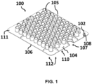
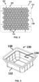
- FIGS. 1 and 2 illustrate a device configured to support a plurality of medical containers or a plurality of components of a medical container therein.
- the device may be referred to in the art generally as a nest.
- the medical containers may be vials, syringes, such as pre-fillable or prefilled syringes, and the like or components of the medical container may be stoppers, syringe gaskets, and the like.
- the medical containers are configured, after filling, to contain a medical fluid therein.
- the device comprises a plate 100 having an upper surface 102, a lower surface 104, and a sidewall 106 extending between the upper surface 102 and the lower surface 104.
- the sidewall 106 defines a perimeter of the plate 100.
- the sidewall 106 comprises four edges connected by corners 111, which may be square or rounded.
- indentations 107 may be formed in edges of the plate 100. Such indentations 107 are configured to be gripped by a person or a machine to facilitate insertion and removal the plate 100 from a tub 130.
- the sidewall 106 is connected to the upper surface 102 at an upper edge 108, and the sidewall 106 is connected to the lower surface 104 at a lower edge 110.
- the upper edge 108, the lower edge 110, and the sidewall 106 collectively define a periphery of the plate 100.
- the plate 100 may comprise a plurality of projections 112.
- the projections 112 are those portions of the plate 100 having the greatest lateral dimensions (e.g., a width or length).
- Each of the projections 112 respectively defines a portion of the periphery of the plate 100.
- the projections 112 are each defined by a portion of the upper surface 102, the lower surface 104, the sidewall 106, the upper edge 108, and the lower edge 110 of the plate 100.
- the plurality of projections 112 define a minority of the periphery of the plate 100, and a remainder of the periphery of the plate 100 is recessed relative to the portion of the sidewall 106 defined by the projections 112.
- a space is provided between the remainder of the sidewall 106 and an interior surface 136 of the tub 130.
- the plate 100 may lack projections.
- a longitudinal axis of the plate 102 extends perpendicular to (e.g., normal to) the upper surface 102.
- the upper surface 102 of the plate 100 is substantially planar.
- the lower surface 104 may also be substantially planar.
- the plate 100 defines a plurality of openings 114 extending therethrough from the upper surface 102 to the lower surface 104. Each opening 114 is configured to retain a medical container or component of a medical container therein.
- the plate 100 may also comprise a plurality of chimneys 105 that protrude axially from the upper surface 102.
- Each chimney 105 extends at least partially circumferentially about a corresponding opening 114.
- Each chimney 105 may be a generally cylindrical structure.
- Each chimney 105 defines an opening within which a medical container may be retained.
- Each chimney 105 may have a centrally extending longitudinal axis that is parallel with the longitudinal axis of the plate 102.
- Each chimney 105 may be integrally formed with the plate 100.
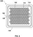
- FIG. 3 illustrates a tub.
- the packaging system 150 comprises at least one plate 100 disposed in the tub 130 for receiving and transporting a plurality of medical containers or components of medical containers.
- the tub 130 comprises a plurality of sidewalls 132.
- the sidewalls 132 may extend from a bottom wall that defines a bottom of the tub 130 to a flange 138 that defines a top of the tub 130.
- the interior of the tub 130 is hollow and is defined by an interior surface of the bottom wall and an interior surface 136 of the sidewalls 132.
- the tub 130 is open such that the plate(s) 100 may be inserted therein.
- the flange 138 may be provided at an end of the sidewalls 132 opposite to which the bottom wall is located. After one or more plates 100 having medical containers or medical container components therein are disposed in the tub 130, a sealing element may be coupled to a surface of the flange 138 to close the opening of the tub 130 and allow for sterilization of the packaging system.
- the plate 100 When the plate 100 is disposed in the tub 130, at least a portion of the sidewall 106 of the plate 100 contacts the interior surface 136 of the tub 130. Further, at least a portion of the upper edge 108 and/or the lower edge 110 contacts the interior surface 136 of the sidewalls 132 of the tub 130.
- the sidewall 106, the upper edge 108, and/or the lower edge 110 defined by the projections contacts the interior surface 136 of the tub 130 while a remainder of the sidewall 106, the upper edge 108, and lower edge 110 are separated from (e.g., not in contact) with the interior surface 136 of the sidewalls of the tub 130.
- the sidewalls 132 of the tub 130 are disposed at an obtuse angle relative to the bottom wall such that the cross-sectional area of the tub 130 decreases between the top and the bottom of the tub 130. In this case, only the lower edge 110 and a portion of the sidewall 106 of the plate 100 may contact the interior surface 136 of the sidewalls of the tub 130.
- the sidewalls 132 of the tub 130 are disposed at a substantially right angle relative to the bottom wall such that the cross-sectional area defined by interior surfaces 136 of the tub 130 is substantially constant between the top and the bottom of the tub 130.
- each of the sidewall 106, the upper edge 108 and the lower edge 110 of the plate 100 may contact the interior surface 136 of the sidewalls of the tub 130.
- the lower edge 110 and/or the upper edge 108 of the plate 100 comprises a curved, or rounded, surface.
- the portion of the upper edge 108 and/or the portion of the lower edge 110 defined by each of the plurality of projections 112 is a curved surface.
- a remainder of the upper edge 108 and/or the lower edge 110 defining the majority of the periphery of the plate 100 may be a straight edge.
- the entirety of the upper edge 108 and/or the lower edge 110 may be a curved surface.
- a radius of curvature of the curved surface is in a range from 0.03 mm to 1 mm, preferably about 0.3 mm.
- the present disclosure also relates to a method of forming the plate 100 such that the upper edge 108 and/or the lower edge 110 comprises a curved surface as previously described herein.
- the plate 100 may be formed in an injection molding process.
- a polymeric material of the plate 100 is injected into a mold 200.
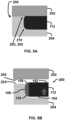
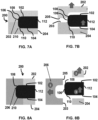
- Partial views of molds 200 usable in an injection molding process are shown in FIGS. 5A-8B .
- the portions of the molds 200 illustrated are cross sections of those portions of the mold 200 having cavities configured to form the projections 112.
- the mold 200 comprises at least one movable part 202 and a fixed part 204.
- the moveable part 202 and the fixed part 204 collectively define a mold cavity 210 to form the plate 100.
- the movable part 202 and/or the fixed part 204 has a curved surface configured to form the curved surface of the portion of the upper edge 108 and/or the portion of the lower edge 110 defined by each of the plurality of projections 112.
- both the upper edge 108 and lower edge 110 have curved surfaces.
- the fixed part 204 is shaped to form the portion of the upper edge 108, the lower edge 110, the sidewall 106, and the lower surface 104 defined by each of the plurality of projections 112.
- the movable part 202 is shaped to form the portion of the upper surface 106 defined by each of the plurality of projections 112.
- the fixed part 204 includes curved surfaces configured to form curved surfaces at the upper edge 108 and the lower edge 110 defined by each of the plurality of projections 112.
- a surface 203 of the movable part 202 and a surface 205 of the fixed part 204 come together for the injection portion of the process and meet at a location referred to in the art as the parting line.
- the parting line is co-located with the upper surface 106 of the plate 100.
- only the lower edge 110 has a curved surface.
- the fixed part 204 is shaped to form the portion of the upper surface 102 and the upper edge 108 defined by the plurality of projections 112
- the at least one movable part 202 is shaped to form the portion of the lower edge 110, the sidewall 106, and the lower surface 104 of the plate 100 defined by the plurality of projections 112.
- the at least one movable part 202 includes curved surfaces configured to form the curved surface of the portion of the lower edge 110 defined by the plurality of projections 112.
- the upper edge 108 defined by the plurality of projections 112 comprises a straight edge.
- a parting line of the fixed part 204 and the at least one movable part 202 is coextensive with the upper surface 102 of the plate 100.
- the mold illustrated in FIGS. 6A and 6B can be used with the fixed part 204 shaped to form the portion of the lower surface and the lower edge defined by the plurality of projections and the movable part 202 including curved surfaces configured to form the curved surface of the upper edge defined by the plurality of projections 112.
- the fixed part 204 is shaped to form the portion of the upper surface 102, the upper edge 108 and the sidewall 106 defined by each of the plurality of projections 112, and the at least one movable part 202 is shaped to form the portion of the lower surface 104, the lower edge 110 and a portion of the sidewall 106 defined by each of the plurality of projections 112.
- Each of the fixed part 204 and the at least one movable part 202 includes curved surfaces to form the curved surface of the upper edge 108 and the lower edge 110 defined by each of the plurality of projections 112.
- the parting line 203 of the fixed part 204 and the at least one movable part 202 is located along the sidewall 106 between the upper surface 102 and the lower surface 104 of the plate 100.
- the movable part 202 includes two distinct mold pieces.
- a movable part 202 comprising a cavity and a slider 206 comprising a cavity.
- the slider 206 is shaped to form the portion of the upper edge 108, the sidewall 106, and the lower edge 110 defined by each of the plurality of projections 112.
- the slider 206 includes curved surfaces to form the curved surface of the upper edge 108 and the lower edge 110 defined by each of the plurality of projections 112.
- a parting line (205) between the slider 206 and the movable part 202 is located along the upper surface 102 of the plate 100, and a parting line (203) of the slider 206 and the fixed part 204 is located along the lower surface 104 of the plate 100.
- parts are subject to flash when molten plastic flows out of the mold 200 along the parting line and solidifies. If such flash is generated along a surface of the projections 112 that contacts the interior surface of the tub 130, particles of the tub 130 or plate 100 may be generated due to rubbing of the flash against the interior surface of the tub 130.
- the method may comprise a step of removing this flash by mechanical methods, such as by cutting, breaking, grinding, or tumbling, or by chemical methods, such as etching, before the medical containers are disposed in the openings 114 of the plate 100 and/or before the plate 100 is disposed in the tub 130.
Landscapes
- Health & Medical Sciences (AREA)
- Vascular Medicine (AREA)
- Engineering & Computer Science (AREA)
- Anesthesiology (AREA)
- Biomedical Technology (AREA)
- Heart & Thoracic Surgery (AREA)
- Hematology (AREA)
- Life Sciences & Earth Sciences (AREA)
- Animal Behavior & Ethology (AREA)
- General Health & Medical Sciences (AREA)
- Public Health (AREA)
- Veterinary Medicine (AREA)
- Moulds For Moulding Plastics Or The Like (AREA)
Priority Applications (3)
| Application Number | Priority Date | Filing Date | Title |
|---|---|---|---|
| EP23306429.4A EP4516336A1 (de) | 2023-08-29 | 2023-08-29 | Vorrichtung und verpackungssystem zum transport von medizinischen geräten |
| CN202480055170.1A CN121752310A (zh) | 2023-08-29 | 2024-08-29 | 用于运输医用装置的装置和包装系统 |
| PCT/EP2024/074215 WO2025046028A1 (en) | 2023-08-29 | 2024-08-29 | Device and packaging system for transporting medical devices |
Applications Claiming Priority (1)
| Application Number | Priority Date | Filing Date | Title |
|---|---|---|---|
| EP23306429.4A EP4516336A1 (de) | 2023-08-29 | 2023-08-29 | Vorrichtung und verpackungssystem zum transport von medizinischen geräten |
Publications (1)
| Publication Number | Publication Date |
|---|---|
| EP4516336A1 true EP4516336A1 (de) | 2025-03-05 |
Family
ID=88017793
Family Applications (1)
| Application Number | Title | Priority Date | Filing Date |
|---|---|---|---|
| EP23306429.4A Pending EP4516336A1 (de) | 2023-08-29 | 2023-08-29 | Vorrichtung und verpackungssystem zum transport von medizinischen geräten |
Country Status (3)
| Country | Link |
|---|---|
| EP (1) | EP4516336A1 (de) |
| CN (1) | CN121752310A (de) |
| WO (1) | WO2025046028A1 (de) |
Citations (5)
| Publication number | Priority date | Publication date | Assignee | Title |
|---|---|---|---|---|
| US20140323981A1 (en) * | 2010-07-16 | 2014-10-30 | Jean-Pierre T. Giraud | Injection molding process and product produced using the same |
| US20180134423A1 (en) * | 2015-04-17 | 2018-05-17 | Schott Kaisha Pvt., Ltd. | Method for closing cartridges, supporting structure for supporting cartridge closures and transport or packaging container |
| EP3851089A1 (de) * | 2020-01-20 | 2021-07-21 | SCHOTT Schweiz AG | Haltevorrichtung zum halten einer vielzahl von behältern in einer formschlüssigen, durch eine verschiebungsbewegung hergestellten verbindung |
| US20220371765A1 (en) * | 2021-05-18 | 2022-11-24 | Gerresheimer Glas Gmbh | Transport tray for packaging units |
| EP4218852A1 (de) * | 2022-01-28 | 2023-08-02 | Becton Dickinson France | Vorrichtung und system zum transportieren von medizinischen vorrichtungen |
-
2023
- 2023-08-29 EP EP23306429.4A patent/EP4516336A1/de active Pending
-
2024
- 2024-08-29 CN CN202480055170.1A patent/CN121752310A/zh active Pending
- 2024-08-29 WO PCT/EP2024/074215 patent/WO2025046028A1/en active Pending
Patent Citations (5)
| Publication number | Priority date | Publication date | Assignee | Title |
|---|---|---|---|---|
| US20140323981A1 (en) * | 2010-07-16 | 2014-10-30 | Jean-Pierre T. Giraud | Injection molding process and product produced using the same |
| US20180134423A1 (en) * | 2015-04-17 | 2018-05-17 | Schott Kaisha Pvt., Ltd. | Method for closing cartridges, supporting structure for supporting cartridge closures and transport or packaging container |
| EP3851089A1 (de) * | 2020-01-20 | 2021-07-21 | SCHOTT Schweiz AG | Haltevorrichtung zum halten einer vielzahl von behältern in einer formschlüssigen, durch eine verschiebungsbewegung hergestellten verbindung |
| US20220371765A1 (en) * | 2021-05-18 | 2022-11-24 | Gerresheimer Glas Gmbh | Transport tray for packaging units |
| EP4218852A1 (de) * | 2022-01-28 | 2023-08-02 | Becton Dickinson France | Vorrichtung und system zum transportieren von medizinischen vorrichtungen |
Also Published As
| Publication number | Publication date |
|---|---|
| WO2025046028A1 (en) | 2025-03-06 |
| CN121752310A (zh) | 2026-03-27 |
Similar Documents
| Publication | Publication Date | Title |
|---|---|---|
| CN115384923B (zh) | 用于同时支撑多个容器的支撑结构以及包括其的运输结构 | |
| CN111196415B (zh) | 其上具有容器的保持结构及具有其的运输或包装容器 | |
| KR101660192B1 (ko) | 의료, 제약 또는 화장품 어플리케이션들을 위한 물질용의 복수의 컨테이너를 동시에 유지하는 유지 구조물과, 이를 포함하는 운송 또는 패키징 컨테이너 | |
| US12122580B2 (en) | Holding structure for simultaneously holding a plurality of containers for substances for pharmaceutical, medical or cosmetic applications, transport unit and transport or packaging container having the same | |
| US11464705B2 (en) | Holding structure for concurrently holding a plurality of containers for substances for pharmaceutical, medical or cosmetic applications, transport structure and transport or packaging container comprising the same | |
| KR102021467B1 (ko) | 의학, 약학 또는 미용 용례용 물질용의 복수 개의 용기를 동시에 지지하기 위한 지지 구조체뿐만 아니라 이를 포함하는 수송 및 포장 용기 그리고 공정 | |
| US6179022B1 (en) | Molded one-piece weighing funnel | |
| CN108341142A (zh) | 支撑多个容器的支撑结构、运输结构以及运输或包装容器 | |
| EP4516336A1 (de) | Vorrichtung und verpackungssystem zum transport von medizinischen geräten | |
| JP2021522017A (ja) | 複数の医療用容器を支持するためのネスト、このネストを含む医療用容器パック、および医療用容器の製造方法 | |
| CN116744988A (zh) | 用于包装柱塞止挡件的具有堆叠销的嵌套件,确保一堆嵌套件的可靠对准 | |
| CN117062755B (zh) | 嵌套件和盒体装置 | |
| WO2025049894A1 (en) | Nest with enlarged interior chimney chamfer | |
| KR102085031B1 (ko) | 주사기형 용기 및 그를 위한 충진장치 | |
| JP6498492B2 (ja) | 保持具およびそれを用いた滅菌方法 | |
| JP2025068241A (ja) | 容器 | |
| CN120817318A (zh) | 具有卡式瓶的集成式定心特征的卡式瓶嵌套装置 |
Legal Events
| Date | Code | Title | Description |
|---|---|---|---|
| PUAI | Public reference made under article 153(3) epc to a published international application that has entered the european phase |
Free format text: ORIGINAL CODE: 0009012 |
|
| STAA | Information on the status of an ep patent application or granted ep patent |
Free format text: STATUS: THE APPLICATION HAS BEEN PUBLISHED |
|
| AK | Designated contracting states |
Kind code of ref document: A1 Designated state(s): AL AT BE BG CH CY CZ DE DK EE ES FI FR GB GR HR HU IE IS IT LI LT LU LV MC ME MK MT NL NO PL PT RO RS SE SI SK SM TR |
|
| STAA | Information on the status of an ep patent application or granted ep patent |
Free format text: STATUS: REQUEST FOR EXAMINATION WAS MADE |
|
| 17P | Request for examination filed |
Effective date: 20250624 |