EP4516261A2 - Embout de stomatologie - Google Patents
Embout de stomatologie Download PDFInfo
- Publication number
- EP4516261A2 EP4516261A2 EP23789361.5A EP23789361A EP4516261A2 EP 4516261 A2 EP4516261 A2 EP 4516261A2 EP 23789361 A EP23789361 A EP 23789361A EP 4516261 A2 EP4516261 A2 EP 4516261A2
- Authority
- EP
- European Patent Office
- Prior art keywords
- diffuser
- optical sensor
- housing
- emitting diode
- light
- Prior art date
- Legal status (The legal status is an assumption and is not a legal conclusion. Google has not performed a legal analysis and makes no representation as to the accuracy of the status listed.)
- Pending
Links
Images

Classifications
-
- A—HUMAN NECESSITIES
- A61—MEDICAL OR VETERINARY SCIENCE; HYGIENE
- A61C—DENTISTRY; APPARATUS OR METHODS FOR ORAL OR DENTAL HYGIENE
- A61C1/00—Dental machines for boring or cutting ; General features of dental machines or apparatus, e.g. hand-piece design
- A61C1/08—Machine parts specially adapted for dentistry
- A61C1/088—Illuminating devices or attachments
-
- A—HUMAN NECESSITIES
- A61—MEDICAL OR VETERINARY SCIENCE; HYGIENE
- A61B—DIAGNOSIS; SURGERY; IDENTIFICATION
- A61B1/00—Instruments for performing medical examinations of the interior of cavities or tubes of the body by visual or photographical inspection, e.g. endoscopes; Illuminating arrangements therefor
- A61B1/24—Instruments for performing medical examinations of the interior of cavities or tubes of the body by visual or photographical inspection, e.g. endoscopes; Illuminating arrangements therefor for the mouth, i.e. stomatoscopes, e.g. with tongue depressors; Instruments for opening or keeping open the mouth
-
- A—HUMAN NECESSITIES
- A61—MEDICAL OR VETERINARY SCIENCE; HYGIENE
- A61C—DENTISTRY; APPARATUS OR METHODS FOR ORAL OR DENTAL HYGIENE
- A61C1/00—Dental machines for boring or cutting ; General features of dental machines or apparatus, e.g. hand-piece design
- A61C1/08—Machine parts specially adapted for dentistry
- A61C1/082—Positioning or guiding, e.g. of drills
-
- A—HUMAN NECESSITIES
- A61—MEDICAL OR VETERINARY SCIENCE; HYGIENE
- A61C—DENTISTRY; APPARATUS OR METHODS FOR ORAL OR DENTAL HYGIENE
- A61C1/00—Dental machines for boring or cutting ; General features of dental machines or apparatus, e.g. hand-piece design
- A61C1/08—Machine parts specially adapted for dentistry
- A61C1/12—Angle hand-pieces
-
- A—HUMAN NECESSITIES
- A61—MEDICAL OR VETERINARY SCIENCE; HYGIENE
- A61C—DENTISTRY; APPARATUS OR METHODS FOR ORAL OR DENTAL HYGIENE
- A61C17/00—Devices for cleaning, polishing, rinsing or drying teeth, teeth cavities or prostheses; Saliva removers; Dental appliances for receiving spittle
- A61C17/02—Rinsing or air-blowing devices, e.g. using fluid jets or comprising liquid medication
- A61C17/0202—Hand-pieces
-
- A—HUMAN NECESSITIES
- A61—MEDICAL OR VETERINARY SCIENCE; HYGIENE
- A61C—DENTISTRY; APPARATUS OR METHODS FOR ORAL OR DENTAL HYGIENE
- A61C17/00—Devices for cleaning, polishing, rinsing or drying teeth, teeth cavities or prostheses; Saliva removers; Dental appliances for receiving spittle
- A61C17/02—Rinsing or air-blowing devices, e.g. using fluid jets or comprising liquid medication
- A61C17/022—Air-blowing devices, e.g. with means for heating the air
-
- A—HUMAN NECESSITIES
- A61—MEDICAL OR VETERINARY SCIENCE; HYGIENE
- A61C—DENTISTRY; APPARATUS OR METHODS FOR ORAL OR DENTAL HYGIENE
- A61C9/00—Impression cups, i.e. impression trays; Impression methods
- A61C9/004—Means or methods for taking digitized impressions
- A61C9/0046—Data acquisition means or methods
- A61C9/0053—Optical means or methods, e.g. scanning the teeth by a laser or light beam
-
- A—HUMAN NECESSITIES
- A61—MEDICAL OR VETERINARY SCIENCE; HYGIENE
- A61B—DIAGNOSIS; SURGERY; IDENTIFICATION
- A61B34/00—Computer-aided surgery; Manipulators or robots specially adapted for use in surgery
- A61B34/20—Surgical navigation systems; Devices for tracking or guiding surgical instruments, e.g. for frameless stereotaxis
- A61B2034/2046—Tracking techniques
- A61B2034/2055—Optical tracking systems
-
- A—HUMAN NECESSITIES
- A61—MEDICAL OR VETERINARY SCIENCE; HYGIENE
- A61C—DENTISTRY; APPARATUS OR METHODS FOR ORAL OR DENTAL HYGIENE
- A61C1/00—Dental machines for boring or cutting ; General features of dental machines or apparatus, e.g. hand-piece design
- A61C1/0061—Air and water supply systems; Valves specially adapted therefor
Definitions
- the present invention relates to a dentistry equipment, and more specifically, to dental handpieces comprising a handle and a housing with an optical emission source represented by at least one light-emitting diode connected to an electric power supply, said handpiece having an optical sensor adapted to be connected to visualization devices, said handpiece can be used by dentists for dental procedures.
- a known example of prior art is a dental handpiece comprising a handle and a housing with an optical emission source represented by at least one light-emitting diode connected to an electric power supply, said housing comprising an optical sensor adapted to be connected to visualization devices, see description of the utility model RU114603U1 .
- Said device is the closest art versus the claimed invention and is considered as a prototype.
- the claimed invention shall be described in terms of differences from the prototype.
- a drawback of said device is that it has a video camera (an optical sensor) which allows to project an image of an oral cavity to an external screen but cannot ensure that no particles from the oral cavity get on its surface during a dental procedure.
- certain tools such as drills, can produce solid fragments flying at high speeds that are capable of crossing over ambient air and getting on the video camera.
- Another major drawback of the prototype is that it does not allow to obtain a high-quality three-dimensional image of the oral cavity wherein the dental handpiece operates.
- the present invention mainly aims to offer a dental handpiece comprising a handle and a housing with an optical emission source represented by at least one first light-emitting diode connected to an electric power supply, said dental handpiece having a first optical sensor adapted to be connected to visualization devices, said dental handpiece being capable of ensuring high-quality stable three-dimensional image, which is a stated technical problem.
- these useful features make it possible to create a powerful air curtain to protect said shielding window from contamination with solid particles and liquid droplets produced during a preparation of the patient's living tissues, that is, to protect the shielding window from getting any particles on external optical components, in other words, to ensure reliable protection of the optical sensor due to implementation of the air curtain.
- the second optical sensor is also reliably protected from getting any particles on external optical components, which makes it possible to create an image of an oral cavity in stereo.
- a virtual 3D model can be generated using pre-rendered CT images.
- Said virtual 3D model can be joined with CT images using optical sensors to view hidden dental cavities so as to get an understanding how a cutting tip is positioned relative to these cavities.
- the housing has a third light-emitting diode connected to an electric power supply, said housing having a third optical sensor adapted to be connected to the visualization devices.
- the housing has a fourth light-emitting diode connected to an electric power supply, said housing having a fourth optical sensor adapted to be connected to the visualization devices.
- each diffuser is located from a working end of the housing and is designed so as to direct the air jet away from the housing end.
- each diffuser is located from the housing handle and is designed so as to direct the air jet away from the handle.
- the housing has a protrusion located from the working end, said protrusion having a surface shape which turns the air jet to 120°-140°.
- the drill bit is located farther from the housing end than the optical sensors.
- the air jet is directed tangentially onto the shielding window and towards the housing end, then gets rotated by the protrusion, that is, under operational conditions, away from a patient's mouth.
- the housing has the protrusion located from the working end, said protrusion having a surface shape which turns the air jet to 120°-140°, the formed jet consists of two echelons with differently directed flows.
- Such complex flow of the high-speed jets makes it possible to increase an efficiency of interception of flying particles by extending their range in velocities and densities. This additionally prevents contamination of the optics.
- each diffuser is oriented perpendicularly to the handle.
- Said diffuser is designed so as to direct the air jet sideways from the handle.
- the housing has a protrusion located from the working end, said protrusion having a surface shape which turns the air jet to 120°-140°.
- each diffuser is designed so as to generate the air jet having an outflow speed ranging from 6 m/s to 50 m/s, said outflow speed forming an angle from 0° to 15° with a plane of the transparent shielding window.
- a compressed air source (dental set compressor) and a dental unit are not shown in the figures.
- a dental handpiece comprises a handle 5 and a housing 50 with an optical emission source represented by at least one first light-emitting diode 13 connected to an electric power supply.
- Said housing 50 comprises a first optical sensor 12 adapted to be connected to visualization devices.
- the housing 50 (more precisely, its optical source) comprises a second light-emitting diode connected to the electric power supply.
- Said housing 50 comprises a second optical sensor adapted to be connected to the visualization devices.
- the housing 50 comprises a first transparent shielding window 15 ( figures 4 to 5 ) of the first optical sensor and a second transparent shielding window of the second optical sensor.
- the handpiece has a means for supplying compressed air on the first and the second shielding windows.
- the housing 50 comprises a first aperture for supplying compressed air to the first shielding window and a second aperture for supplying compressed air to the second shielding window, both apertures being connected to the means for supplying compressed air.
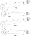
- Each aperture has a diffuser that is designed so as to generate an air jet forming an air curtain in front of the transparent shielding window. See figures 1 to 9 .
- the housing 50 optionally comprises a third light-emitting diode connected to the electric power supply.
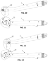
- Said housing 50 (more precisely, its optical source) comprises a third optical sensor adapted to be connected to the visualization devices. See figures 10 to 13 .
- the housing 50 optionally comprises a fourth light-emitting diode connected to an electric power supply.
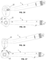
- Said housing 50 (more precisely, its optical source) comprises a fourth optical sensor adapted to be connected to the visualization devices. See figures 14 to 17 .
- Each diffuser can be located on a side of a working end of the housing and can be designed so as to direct the air jet away from the working end of the housing. See figure 4 .
- Each diffuser can be located on the handle side of the housing and can be designed so as to direct the airjet away from the handle of the housing.
- the housing has a protrusion located from the working end, said protrusion having a surface shape which turns the air jet to 120°-140°. See figure 5 .
- Each diffuser can be oriented perpendicularly to the handle of the housing and can be designed so as to direct the air jet away from the handle of the housing.
- the housing has a protrusion located from the working end, said protrusion having a surface shape which turns the air jet to 120°-140°.
- Each diffuser can be designed so as to generate the air jet with an outflow speed ranging from 6 m/s to 50 m/s and forming an angle from 0°-15° with a plane of the transparent shielding window.
- Said dental handpiece is also designed with several air supply options: direct and reverse (with turning of the air curtain), and in different locations of the optical sensors depending on their number from two to four.
- the dental handpiece operates as follows. Below is the most exhaustive example of the embodiment of the invention, however, said example does not limit other applications of the invention.
- a compressed air is supplied from a dental unit compressor through a compressed air supplying tube 11 as a channeled air jet (inside a handle 5) to a housing 50.
- a compressed air supplying tube 11 as a channeled air jet (inside a handle 5)
- the air passes through the housing 50, it goes to directional diffusers 14 that form a flat jet directed at an angle up to 15 degrees versus a housing surface, with an outflow speed ranging from 6 m/s to 50 m/s.
- the high-speed jet does not allow foreign particles having densities and speeds typical for dental interventions pass through its core and moves them away from each shielding window of each optical sensor.
- Quantitative attributes of the technical parameters such as an air jet turning angle, the airjet outflow speed and the angle between the airjet outflow and the transparent shielding window plane in a range of continuously changing variables can be adjusted by varying a protrusion and the diffuser geometry.
- Blowing efficiency control method shall be a visual control of readability of the image transferred from the optical sensor and contaminated with artifacts due to foreign particles and liquid droplets getting onto the shielding window.
- a number of image artifacts shall be assumed as a criterion of blowing efficiency in four tiers: "none” - there is no visible artifacts from foreign particles and liquid droplets, “moderate” - foreign particles and liquid droplets are not retained on the surface of the transparent shielding window and do not affect a readability of the transferred image, “medium” - foreign particles and liquid droplets remain on the surface of the shielding window and affect the image transferred from the optical sensor, with readability remaining sufficient to direct the dental handpiece in an operating environment, "severe” - foreign particles and liquid droplets remain on the surface of the shielding window, making the image from the optical sensor unreadable and not suitable for correct orientation of the dental handpiece in the operating environment.
- An air jet rotation angle is adjusted in the range from 120° to 140° by adjusting a shape of the protrusion surface directed at the diffuser.
- a value of a protrusion incline angle shall be a geometrical parameter for an air jet turning angle.
- the protrusion incline angle is found between a tangential line to the margin of the concave surface and a plane of the transparent shielding window. See Table 1 for a relationship between the air jet turning angles, image artifact grade, and the above geometrical parameter. See figure 1 for an example of the embodiment of the invention with borderline values of said range. Table 1. Dependence of an air jet turning angle and an image artifact grade from a protrusion incline angle. No Air jet turning angle, degrees Value of a protrusion incline angle, degrees Image artifact grade 1 115 85 Medium 2 120 80 Moderate 3 125 75 Moderate 4 130 70 None 5 135 65 None 6 140 60 None
- An air jet outflow speed was adjusted in a range from 6 m/s to 50 m/s by adjusting the diffuser outlet cross-section area.
- a geometrical parameter characterizing the airjet outflow speed was a value of a round section diameter with the same area as the diffuser outlet cross-section. See Table 2 for a relationship between an air jet outflow, an image artifact grade, and the above-mentioned geometrical parameter. Table 2. Dependence of air jet outflow speed and image artifact grade from equivalent round section diameter.
- An angle between an air curtain outflow direction and a shielding window plane was adjusted in a range from 0 to 15 degrees by adjusting a diffuser outlet cross-section aperture angle.
- the diffuser outlet cross-section aperture angle was assumed as a characteristic geometrical parameter. See Table 3 for a dependence of an angle between the direction of the air curtain outflow direction and shielding window plane, an image artifact grade and the above geometrical parameter. Table 3. Dependence of an angle between the direction of the air curtain outflow direction and shielding window plane, an image artifact grade and a diffuser outlet cross-section aperture angle.
- optical sensors make it possible to obtain a three-dimensional image of an oral cavity.
- an operator of the dental handpiece according to the invention will be able to see a three-dimensional image on a screen during any interventions in the oral cavity.
- a virtual three-dimensional (3D) model can be generated using pre-rendered CT images.
- Said virtual three-dimensional (3D) model can be joined with CT images using optical sensors. Under these conditions, an operator of the dental handpiece according to the invention will be able to view hidden dental cavities and get an understanding how a cutting tip is positioned relative to these cavities.
- the claimed dental handpiece may be implemented by a person skilled in the art in practice and ensures that the claimed objectives are met after implementation, which leads to the conclusion that the invention meets the requirement of "industrial applicability".
- the invention relates to a dental handpiece comprising:
- the optical emission source further comprises a second light-emitting diode different from the first light-emitting diode 13.
- the second light-emitting diode is connected to the electric power supply.
- the housing 50 further comprises:
- the dental handpiece S further comprise a means for supplying compressed air 11 on the first shielding window 15 and on the second transparent shielding window.
- the housing 50 further comprises:
- a first diffuser 14 is located in the first aperture. Said first diffuser 14 is adapted to generate an air jet forming an air curtain in front of the first transparent shielding window 15.
- a second diffuser different from the first diffuser 14 is located in the second aperture. Said second diffuser is adapted to generate an air jet forming an air curtain in front of the second transparent shielding window.
- the optical emission source further comprises a third light-emitting diode different from the first light-emitting diode and the second light-emitting diode.
- Said third light-emitting diode is connected to the electric power supply.
- the housing 50 further comprises a third optical sensor different from the first optical sensor 12 and the second optical sensor 120. Said third optical sensor is adapted to be connected to the visualization devices.
- the optical emission source further comprises a fourth light-emitting diode different from the first light-emitting diode, the second light-emitting diode and the third light-emitting diode.
- Said fourth light-emitting diode is connected to the electric power supply.
- the housing 50 further comprises a fourth optical sensor different from the first optical sensor 12, the second optical sensor 120 and the third optical sensor. Said fourth optical sensor is adapted to be connected to the visualization devices.
- each diffuser among the first diffuser 14 and the second diffuser is located from a working end of the housing 50. Said each diffuser is adapted to direct the air jet away from the working end of the housing 50 along the axis MN of the handle 5.
- each diffuser among the first diffuser 14 and the second diffuser is located from the working end of the housing 50.
- Said each diffuser is adapted to direct the air jet away from the working end of the housing 50 along the axis MN of the handle 5.
- the housing 50 comprises a protrusion 16 located from the working end of the housing 50.
- the protrusion has a surface shape which turns the air jet outgoing from the respective diffuser in a first angle comprising in a first interval from 120° to 140°.
- each diffuser among the first diffuser 14 and the second diffuser is oriented perpendicularly to the handle 5.
- Each diffuser among the first diffuser 14 and the second diffuser is adapted to direct the air jet sideways from the handle 5.
- the housing 50 comprises a protrusion located from the working end.
- the protrusion has a surface shape which turns the air jet outgoing from the respective diffuser by the first angle comprising in the first interval from 120° to 140°.
- each diffuser among the first diffuser 14 and the second diffuser is adapted to generate the air jet with an outflow speed ranging from 6 m/s to 50 m/s.
- Said air jet outflow speed forms a second angle with a plane of the transparent shielding window corresponding to said each diffuser, said second angle being comprised in a second interval from 0° to 15°.
- any light-emitting diode among the above first light-emitting diode, second light-emitting diode, third light-emitting diode, fourth light-emitting diode can present punctual geometry.
- any light-emitting diode from the above has especially a ring pattern as shown in the examples in figures 4 and 5 : according to the applicant's observations, such ring pattern ensures the most uniform (without hotspots and/or shadows) lighting of an oral cavity sufficient to obtain a high-quality three-dimensional image.
Landscapes
- Health & Medical Sciences (AREA)
- Life Sciences & Earth Sciences (AREA)
- Oral & Maxillofacial Surgery (AREA)
- General Health & Medical Sciences (AREA)
- Animal Behavior & Ethology (AREA)
- Public Health (AREA)
- Veterinary Medicine (AREA)
- Dentistry (AREA)
- Epidemiology (AREA)
- Physics & Mathematics (AREA)
- Optics & Photonics (AREA)
- Surgery (AREA)
- Nuclear Medicine, Radiotherapy & Molecular Imaging (AREA)
- Pathology (AREA)
- Radiology & Medical Imaging (AREA)
- Biophysics (AREA)
- Engineering & Computer Science (AREA)
- Biomedical Technology (AREA)
- Heart & Thoracic Surgery (AREA)
- Medical Informatics (AREA)
- Molecular Biology (AREA)
- Dental Tools And Instruments Or Auxiliary Dental Instruments (AREA)
- Led Device Packages (AREA)
Applications Claiming Priority (2)
| Application Number | Priority Date | Filing Date | Title |
|---|---|---|---|
| RU2022111203A RU2782094C1 (ru) | 2022-04-25 | Стоматологический наконечник | |
| PCT/IB2023/054260 WO2023209575A2 (fr) | 2022-04-25 | 2023-04-25 | Embout de stomatologie |
Publications (1)
| Publication Number | Publication Date |
|---|---|
| EP4516261A2 true EP4516261A2 (fr) | 2025-03-05 |
Family
ID=88373709
Family Applications (1)
| Application Number | Title | Priority Date | Filing Date |
|---|---|---|---|
| EP23789361.5A Pending EP4516261A2 (fr) | 2022-04-25 | 2023-04-25 | Embout de stomatologie |
Country Status (5)
| Country | Link |
|---|---|
| US (1) | US20250295301A1 (fr) |
| EP (1) | EP4516261A2 (fr) |
| JP (1) | JP2025517036A (fr) |
| CN (1) | CN119421670A (fr) |
| WO (1) | WO2023209575A2 (fr) |
Families Citing this family (3)
| Publication number | Priority date | Publication date | Assignee | Title |
|---|---|---|---|---|
| US20250031953A1 (en) * | 2023-07-29 | 2025-01-30 | Suhaib Harraka | System and method for in-situ removal of accumulated moisture and debris from an intraoral amera |
| JP1805985S (ja) * | 2024-05-06 | 2025-08-13 | 口腔洗浄器の先端 | |
| WO2026074519A1 (fr) * | 2024-10-04 | 2026-04-09 | Михальский Александр | Embout de stomatologie |
Family Cites Families (9)
| Publication number | Priority date | Publication date | Assignee | Title |
|---|---|---|---|---|
| FR2651428A1 (fr) * | 1989-09-06 | 1991-03-08 | Bleicher Paul | Outil de dentisterie, notamment contre-angle de fraisage a controle-visuel. |
| DE19511262C1 (de) * | 1995-03-27 | 1996-08-22 | Siemens Ag | Zahnärztliches Behandlungsinstrument mit Beleuchtungseinrichtung |
| US5634790A (en) * | 1995-06-07 | 1997-06-03 | Lares Research | Video dental medical instrument |
| US20050084816A1 (en) * | 2003-10-21 | 2005-04-21 | Mehdizadeh Bahman M. | Systems and methods for performing dental operations |
| DE112009001210T5 (de) * | 2008-06-06 | 2011-03-31 | J.Morita Manufacturing Corp., KYOTO-SHI | Bildaufnahmevorrichtung verwendet zur Zahnbehandlung und Gerät zur Zahnbehandlung ausgestattet mit einer Bildaufnahmevorrichtung |
| KR20110001515U (ko) * | 2009-08-06 | 2011-02-14 | 양원동 | 살균력을 갖는 핸드피스 |
| JP6262936B2 (ja) * | 2012-08-31 | 2018-01-17 | 株式会社吉田製作所 | カメラ内蔵ハンドピース |
| JP6324680B2 (ja) * | 2013-08-02 | 2018-05-16 | 株式会社吉田製作所 | 撮像窓曇り防止機能付カメラ内蔵ハンドピース |
| CN108712888A (zh) * | 2016-09-29 | 2018-10-26 | 株式会社Gc | 空气喷射装置及牙科机头系统 |
-
2023
- 2023-04-25 WO PCT/IB2023/054260 patent/WO2023209575A2/fr not_active Ceased
- 2023-04-25 JP JP2024563651A patent/JP2025517036A/ja active Pending
- 2023-04-25 EP EP23789361.5A patent/EP4516261A2/fr active Pending
- 2023-04-25 US US18/860,050 patent/US20250295301A1/en active Pending
- 2023-04-25 CN CN202380049541.0A patent/CN119421670A/zh active Pending
Also Published As
| Publication number | Publication date |
|---|---|
| WO2023209575A3 (fr) | 2024-02-29 |
| JP2025517036A (ja) | 2025-06-02 |
| CN119421670A (zh) | 2025-02-11 |
| WO2023209575A2 (fr) | 2023-11-02 |
| US20250295301A1 (en) | 2025-09-25 |
Similar Documents
| Publication | Publication Date | Title |
|---|---|---|
| EP4516261A2 (fr) | Embout de stomatologie | |
| US12097081B2 (en) | Laser based computer controlled dental preparation system | |
| ES2868999T3 (es) | Aparato de láser dental y método de uso con pieza de mano intercambiable y pedal variable | |
| JP6830876B2 (ja) | 内視鏡 | |
| ES2660824T3 (es) | Dispositivo de tratamiento con energía electromagnética con plataforma de satélite | |
| EP4424225A1 (fr) | Embout de stomatologie | |
| US20090105707A1 (en) | Drill and flavored fluid particles combination | |
| EP0073617A1 (fr) | Pièce à main dentaire pour laser | |
| US20100125291A1 (en) | Drill and flavored fluid particles combination | |
| CN101384226A (zh) | 具增大部位尺寸的电磁能发射装置 | |
| CN101223464A (zh) | 与电磁能程序设备一起使用的编码输出附件 | |
| WO2021015599A1 (fr) | Robot de traitement dentaire | |
| CN109480355A (zh) | 复合式口腔医生防护面罩 | |
| RU2782094C1 (ru) | Стоматологический наконечник | |
| EP4400026A1 (fr) | Endoscope intra-oral | |
| US20230320800A1 (en) | Surgical Tool with Targeting Guidance | |
| RU2772017C1 (ru) | Стоматологический наконечник | |
| Dong et al. | WIP: a study on the development of endodontic micro robot | |
| RU2773600C1 (ru) | Интраоральный эндоскоп | |
| WO2020212858A1 (fr) | Appareil dentaire et son procédé de fonctionnement |
Legal Events
| Date | Code | Title | Description |
|---|---|---|---|
| STAA | Information on the status of an ep patent application or granted ep patent |
Free format text: STATUS: UNKNOWN |
|
| STAA | Information on the status of an ep patent application or granted ep patent |
Free format text: STATUS: THE INTERNATIONAL PUBLICATION HAS BEEN MADE |
|
| PUAI | Public reference made under article 153(3) epc to a published international application that has entered the european phase |
Free format text: ORIGINAL CODE: 0009012 |
|
| STAA | Information on the status of an ep patent application or granted ep patent |
Free format text: STATUS: REQUEST FOR EXAMINATION WAS MADE |
|
| 17P | Request for examination filed |
Effective date: 20241121 |
|
| AK | Designated contracting states |
Kind code of ref document: A2 Designated state(s): AL AT BE BG CH CY CZ DE DK EE ES FI FR GB GR HR HU IE IS IT LI LT LU LV MC ME MK MT NL NO PL PT RO RS SE SI SK SM TR |
|
| DAV | Request for validation of the european patent (deleted) | ||
| DAX | Request for extension of the european patent (deleted) | ||
| STAA | Information on the status of an ep patent application or granted ep patent |
Free format text: STATUS: EXAMINATION IS IN PROGRESS |
|
| 17Q | First examination report despatched |
Effective date: 20260318 |