EP4516256A1 - Hook for medical devices, and medical device - Google Patents
Hook for medical devices, and medical device Download PDFInfo
- Publication number
- EP4516256A1 EP4516256A1 EP23795970.5A EP23795970A EP4516256A1 EP 4516256 A1 EP4516256 A1 EP 4516256A1 EP 23795970 A EP23795970 A EP 23795970A EP 4516256 A1 EP4516256 A1 EP 4516256A1
- Authority
- EP
- European Patent Office
- Prior art keywords
- medical
- inset
- hook
- tubular
- distal tip
- Prior art date
- Legal status (The legal status is an assumption and is not a legal conclusion. Google has not performed a legal analysis and makes no representation as to the accuracy of the status listed.)
- Pending
Links
Images



Classifications
-
- A—HUMAN NECESSITIES
- A61—MEDICAL OR VETERINARY SCIENCE; HYGIENE
- A61B—DIAGNOSIS; SURGERY; IDENTIFICATION
- A61B50/00—Containers, covers, furniture or holders specially adapted for surgical or diagnostic appliances or instruments, e.g. sterile covers
- A61B50/20—Holders specially adapted for surgical or diagnostic appliances or instruments
-
- A—HUMAN NECESSITIES
- A61—MEDICAL OR VETERINARY SCIENCE; HYGIENE
- A61B—DIAGNOSIS; SURGERY; IDENTIFICATION
- A61B1/00—Instruments for performing medical examinations of the interior of cavities or tubes of the body by visual or photographical inspection, e.g. endoscopes; Illuminating arrangements therefor
- A61B1/00131—Accessories for endoscopes
-
- A—HUMAN NECESSITIES
- A61—MEDICAL OR VETERINARY SCIENCE; HYGIENE
- A61B—DIAGNOSIS; SURGERY; IDENTIFICATION
- A61B1/00—Instruments for performing medical examinations of the interior of cavities or tubes of the body by visual or photographical inspection, e.g. endoscopes; Illuminating arrangements therefor
- A61B1/00131—Accessories for endoscopes
- A61B1/0014—Fastening element for attaching accessories to the outside of an endoscope, e.g. clips, clamps or bands
-
- A—HUMAN NECESSITIES
- A61—MEDICAL OR VETERINARY SCIENCE; HYGIENE
- A61B—DIAGNOSIS; SURGERY; IDENTIFICATION
- A61B18/00—Surgical instruments, devices or methods for transferring non-mechanical forms of energy to or from the body
- A61B18/04—Surgical instruments, devices or methods for transferring non-mechanical forms of energy to or from the body by heating
- A61B18/12—Surgical instruments, devices or methods for transferring non-mechanical forms of energy to or from the body by heating by passing a current through the tissue to be heated, e.g. high-frequency current
- A61B18/14—Probes or electrodes therefor
- A61B18/1482—Probes or electrodes therefor having a long rigid shaft for accessing the inner body transcutaneously in minimal invasive surgery, e.g. laparoscopy
-
- A—HUMAN NECESSITIES
- A61—MEDICAL OR VETERINARY SCIENCE; HYGIENE
- A61B—DIAGNOSIS; SURGERY; IDENTIFICATION
- A61B1/00—Instruments for performing medical examinations of the interior of cavities or tubes of the body by visual or photographical inspection, e.g. endoscopes; Illuminating arrangements therefor
- A61B1/00147—Holding or positioning arrangements
-
- A—HUMAN NECESSITIES
- A61—MEDICAL OR VETERINARY SCIENCE; HYGIENE
- A61B—DIAGNOSIS; SURGERY; IDENTIFICATION
- A61B18/00—Surgical instruments, devices or methods for transferring non-mechanical forms of energy to or from the body
- A61B18/04—Surgical instruments, devices or methods for transferring non-mechanical forms of energy to or from the body by heating
- A61B18/12—Surgical instruments, devices or methods for transferring non-mechanical forms of energy to or from the body by heating by passing a current through the tissue to be heated, e.g. high-frequency current
- A61B18/14—Probes or electrodes therefor
- A61B18/1492—Probes or electrodes therefor having a flexible, catheter-like structure, e.g. for heart ablation
-
- A—HUMAN NECESSITIES
- A61—MEDICAL OR VETERINARY SCIENCE; HYGIENE
- A61B—DIAGNOSIS; SURGERY; IDENTIFICATION
- A61B18/00—Surgical instruments, devices or methods for transferring non-mechanical forms of energy to or from the body
- A61B2018/00315—Surgical instruments, devices or methods for transferring non-mechanical forms of energy to or from the body for treatment of particular body parts
- A61B2018/00482—Digestive system
- A61B2018/00494—Stomach, intestines or bowel
-
- A—HUMAN NECESSITIES
- A61—MEDICAL OR VETERINARY SCIENCE; HYGIENE
- A61B—DIAGNOSIS; SURGERY; IDENTIFICATION
- A61B18/00—Surgical instruments, devices or methods for transferring non-mechanical forms of energy to or from the body
- A61B2018/00571—Surgical instruments, devices or methods for transferring non-mechanical forms of energy to or from the body for achieving a particular surgical effect
- A61B2018/00601—Cutting
-
- A—HUMAN NECESSITIES
- A61—MEDICAL OR VETERINARY SCIENCE; HYGIENE
- A61B—DIAGNOSIS; SURGERY; IDENTIFICATION
- A61B90/00—Instruments, implements or accessories specially adapted for surgery or diagnosis and not covered by any of the groups A61B1/00 - A61B50/00, e.g. for luxation treatment or for protecting wound edges
- A61B90/50—Supports for surgical instruments, e.g. articulated arms
- A61B90/57—Accessory clamps
Definitions
- the present invention relates to a medical-device hook and a medical device.
- Patent Literature 1 describes a specific configuration of such a type of medical device.
- the medical device described in Patent Literature 1 includes an operation body that a surgical operator (medical doctor) operates, in which the operation body has a base end portion to which a hook is attached.
- a surgical operator medical doctor
- the operation body has a base end portion to which a hook is attached.
- a case where the tubular portion is laid on the surface of a floor with the medical device suspended by hanging the hook on a hanger is unfavorable in terms of hygiene.
- the surgical operator is likely to step on the tubular portion, leading to damage of the tubular portion.
- the medical device described in Patent Literature 1 has, on its operation body, a locking groove for locking the tubular portion.
- the tubular portion is hung on the locking groove such that the tubular portion is suspended.
- the tubular portion requires no laying on the surface of a floor.
- Patent Literature 1 JP S63-166209 U1
- Patent Literature 1 in a case where the tubular portion has a large self-weight, due to a large load to the tubular portion through a portion in contact with the locking groove, the tubular portion is likely to buckle. In Patent Literature 1, in a case where the tubular portion has a small self-weight, due to a small degree of hanging on the locking groove, the tubular portion is likely to drop from the locking groove.
- the present invention has been made in consideration of the above situation, and an object of the present invention is to provide a medical-device hook favorable for holding a tubular portion of a medical device having been suspended and a medical device including such a medical-device hook.
- a medical-device hook to be attached to a medical device including a tubular portion to be inserted into a body lumen, the medical-device hook including: an inset opening allowing the tubular portion to be inset into the inset opening; and a surrounding portion around the inset opening, the surrounding portion being configured to deform elastically to come in close contact with the tubular portion inset in the inset opening such that the tubular portion is held due to frictional resistance on a closely contacted portion between the surrounding portion around the inset opening and the tubular portion.
- the surrounding portion around the inset opening may deform elastically, due to a weight of the medical device, to come in close contact with the tubular portion inset in the inset opening such that the tubular portion is held due to the frictional resistance on the closely contacted portion.
- the surrounding portion around the inset opening may deform elastically to come in close contact with the tubular portion such that the tubular portion is held due to the frictional resistance on the closely contacted portion.
- the inset opening may include a hole or a slit.
- the inset opening includes, for example, a hole having a diameter larger than an outer diameter of the tubular portion.
- the inset opening includes, for example, a slit having a width narrower than an outer diameter of the tubular portion.
- the medical-device hook is formed of elastomer resin.
- a medical device including: a tubular portion to be inserted into a body lumen; a grip portion connected to a base end portion of the tubular portion; and the medical-device hook described above, the medical-device hook being attached to a base end portion of the grip portion.
- the medical-device hook is attached to the grip portion so as to pose at a slant with respect to a direction of gravity when the medical-device hook is hung on a hanger.
- a medical-device hook favorable for holding a tubular portion of a medical device having been suspended and a medical device including such a medical-device hook.
- a medical-device hook according to the present embodiment is attached to a medical device including a tubular portion to be inserted into a body lumen.
- the medical-device hook is attached to an endoscope treatment tool including a high-frequency knife that excises, for example, a mucous membrane due to passage of a high-frequency current in endoscopic submucosal dissection (ESD).
- ESD endoscopic submucosal dissection
- a medical device to which the medical-device hook according to the present embodiment is to be attached is not limited to such an endoscope treatment tool.
- the medical-device hook may be attached to a different type of medical device including a tubular portion to be inserted into a body lumen (e.g., an endoscope).
- Fig. 1 illustrates the entirety of an endoscope treatment tool 2 to which a hook 1 according to a first embodiment of the present invention is attached.
- the hook 1 is an exemplary medical-device hook.
- the endoscope treatment tool 2 includes a tubular portion 2A and a grip portion 2B, in addition to the hook 1.
- the tubular portion 2A serves as a portion to be inserted into a body lumen (more particularly, a portion that has passed through a channel of an endoscope and is to be inserted into a body lumen) and has flexibility to deform following organs in a body lumen.
- the tubular portion 2A has a distal tip 2Aa (hereinafter, referred to as a "tubular distal tip 2Aa") in which a high-frequency knife is provided.
- the grip portion 2B serves as a portion to be gripped by a surgical operator and is connected to the base end portion of the tubular portion 2A.
- the grip portion 2B is provided with an operation unit 2Ba to be operated by a surgical operator.
- a change is made in the amount of protrusion of the high-frequency knife to the tip face of the tubular distal tip 2Aa.
- the surgical operator operates the operation unit 2Ba, in accordance with procedure details (e.g., marking, local injection, incision, exfoliation, or hemostasis), to cause the high-frequency knife to protrude from the tip face of the tubular distal tip 2Aa by an appropriate amount.
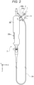
- Fig. 2 illustrates a state where the endoscope treatment tool 2 is suspended with the hook 1 hung on a hanger 3.
- Fig. 3 is an arrow view of the hook 1 hung on the hanger 3 viewed in the direction of an arrow A in Fig. 2 .
- the up-and-down direction is defined as a Z direction and two directions orthogonal to the Z direction and orthogonal to each other are defined as an X direction and a Y direction.
- the X direction, the Y direction, and the Z direction orthogonal to each other form a left-handed system.
- the positive Z direction corresponds to the direction of gravity.
- the hook 1 is a resin molded product including a body portion 110 and a connection portion 120 integrally formed together.
- the hook 1 is formed of elastomer resin, such as silicone rubber or fluororubber. Thus, the hook 1 deforms elastically depending on an applied load.
- the body portion 110 is annular in shape and has a hole 112. Hanging is performed on the hanger 3 through the hole 112.
- connection portion 120 connects the body portion 110 and the grip portion 2B.
- the connection portion 120 is shaped like a flat plate that is wide laterally (in the Y direction, referring to Fig. 3 ).
- the connection portion 120 has a front end (on the negative side in the Z direction, referring to Fig. 3 ) integrated with the body portion 110 and a base end portion (on the positive side in the Z direction, referring to Fig. 3 ) embedded in a base end portion 2Bb of the grip portion 2B.
- An inset hole 122 as an exemplary inset opening is located at the center in the width direction of the connection portion 120 (at the center in the Y direction, referring to Fig. 3 ) and below the hole 112 in a case where the hook 1 is hung on the hanger 3.
- the inset hole 122 is a circular hole having a diameter larger than the outer diameter of the tubular distal tip 2Aa of the endoscope treatment tool 2 (referring to Fig. 4A described later). That is, the tubular distal tip 2Aa can be inset into the inset hole 122.
- the inset hole 122 is not limited to such a circular hole and thus may be a hole in any shape (e.g., an elliptical hole or a polygonal hole).
- a surrounding portion around the inset hole 122 is referred to as a "surrounding portion 124".
- the surgical operator or any other health professional hangs the hook 1 on the hanger 3 provided on an indoor wall face to suspend the endoscope treatment tool 2.
- a physician assistant or a nurse hangs the hook 1 on the hanger 3 provided on an indoor wall face to suspend the endoscope treatment tool 2.
- anyone who suspends the endoscope treatment tool 2 is generically referred to as a worker.
- the worker insets the tubular distal tip 2Aa into the inset hole 122 and then hangs the hook 1 on the hanger 3.
- Fig. 4A illustrates a state where the tubular distal tip 2Aa is inset in the inset hole 122. As illustrated in Fig. 4A , since the diameter of the inset hole 122 is larger than the outer diameter of the tubular distal tip 2Aa, the worker can easily inset the tubular distal tip 2Aa into the inset hole 122.
- Fig. 4B illustrates the state of the inset hole 122 with the hook 1 hung on the hanger 3.
- the hook 1 is hung on the hanger 3, due to the weight of the endoscope treatment tool 2, almost the entirety of the hook 1 including the surrounding portion 124 around the inset hole 122 deforms elastically to extend slightly in the Z direction.
- the inset hole 122 deforms from its circular shape to an elliptical shape having its major axis and minor axis, respectively, in the Z direction and the Y direction, as illustrated in Fig. 4B .
- Part of the surrounding portion 124 elastically deformed such that the inset hole 122 narrows in the Y direction is in close contact with the tubular distal tip 2Aa inset in the inset hole 122.
- Such close contact between the surrounding portion 124 and the tubular distal tip 2Aa causes adequate frictional resistance therebetween.
- the tubular distal tip 2Aa is firmly held by the surrounding portion 124 without dropping from the inset hole 122.
- the hook 1 allows the surrounding portion 124 around the inset hole 122 to deform elastically due to the self-weight of the endoscope treatment tool 2 having been suspended.
- Such elastic deformation of the surrounding portion 124 causes the surrounding portion 124 to come in close contact with the tubular distal tip 2Aa inset in the inset hole 122, so that the tubular distal tip 2Aa is held due to frictional resistance on the closely contacted portion between the surrounding portion 124 and the tubular distal tip 2Aa.
- the surrounding portion 124 and the tubular distal tip 2Aa come in close surface contact.
- the load on the tubular distal tip 2Aa is more dispersed, in comparison to the configuration described in Patent Literature 1.
- the tubular distal tip 2Aa is less likely to buckle.
- the hook 1 is made of elastomer resin large in static friction coefficient. Thus, adequate frictional resistance occurs between the surrounding portion 124 and the tubular distal tip 2Aa.
- the tubular distal tip 2Aa is less likely to drop from the inset hole 122.
- the hook 1 is attached to the base end portion 2Bb of the grip portion 2B so as to pose at a slant with respect to the direction of gravity (with respect to the positive Z direction) when the hook 1 is hung on the hanger 3.
- the hook 1 does not deform elastically to extend only in the Z direction but deforms elastically, due to the self-weight of the endoscope treatment tool 2, not only to bend in the direction of an arrow B resulting from composition of the positive Z direction and the positive X direction but also to extend in the direction of an arrow C resulting from composition of the positive Z direction and the negative X direction.
- the surrounding portion 124 deforms elastically to bend, and thus the load from the surrounding portion 124 to the tubular distal tip 2Aa is dispersed in various directions through the closely contacted portion between the surrounding portion 124 and the tubular distal tip 2Aa. From this regard, the tubular distal tip 2Aa is less likely to drop from the inset hole 122.
- Fig. 5 illustrates a hook 201 according to a second embodiment of the present invention. Note that hooks according to the following embodiments including the second embodiment are each attached to an endoscope treatment tool 2, similarly to the first embodiment. Fig. 5 is an arrow view of the hook 201 hung on a hanger 3, similarly to Fig. 3 .
- the hook 201 is a resin molded product including a body portion 210 and a connection portion 220 integrally formed together, and deforms elastically depending on an added load.
- the body portion 210 is annular in shape and has a hole 212.
- connection portion 220 is shaped like a flat plate that is wide laterally.
- the connection portion 220 has a front end integrated with the body portion 210 and a base end portion embedded in a base end portion 2Bb of a grip portion 2B.
- the hook 201 includes a protrusion 226 protruding laterally from the connection portion 220 near the boundary between the body portion 210 and the connection portion 220.
- the protrusion 226 extends along an outer circumferential face 210A of the body portion 210.
- a slit 222 is provided as an exemplary inset opening between the outer circumferential face 210A of the body portion 210 and the protrusion 226.
- the slit 222 includes a linear slit portion (linear portion 222a) and a circular slit portion (circular portion 222b).
- the width of the linear portion 222a is narrower than the outer diameter of a tubular distal tip 2Aa, and the diameter of the circular portion 222b is smaller than the outer diameter of the tubular distal tip 2Aa.
- a surrounding portion around the circular portion 222b is referred to as a "surrounding portion 224".
- the hook 201 deforms elastically depending on an added load. Thus, a worker can easily inset the tubular distal tip 2Aa into the slit 222.
- Figs. 6A and 6B illustrate how the tubular distal tip 2Aa is inset into the slit 222.
- the protrusion 226 is pushed and moved in the direction of an arrow D, so that the linear portion 222a widens.
- the load to the protrusion 226 due to the tubular distal tip 2Aa drops to almost zero.
- the protrusion 226 moves in the direction of an arrow E, so that the linear portion 222a gets back an almost original width.
- the diameter of the circular portion 222b is smaller than the outer diameter of the tubular distal tip 2Aa.
- the surrounding portion 224 around the circular portion 222b deforms elastically such that the circular portion 222b is pushed and widened along the outer diameter of the tubular distal tip 2Aa.
- the surrounding portion 224 comes in close contact with the tubular distal tip 2Aa inset in the circular portion 222b. Such close contact between the surrounding portion 224 and the tubular distal tip 2Aa causes adequate frictional resistance therebetween. Thus, the tubular distal tip 2Aa is firmly held by the surrounding portion 224 without dropping from the circular portion 222b.
- the width of the linear portion 222a is narrower than the diameter of the circular portion 222b. Thus, even in a case where the tubular distal tip 2Aa comes off the circular portion 222b, the tubular distal tip 2Aa is less likely to drop through the linear portion 222a.
- the hook 201 allows the surrounding portion 224 to deform elastically following the tubular distal tip 2Aa inset in the slit 222. Due to such elastic deformation of the surrounding portion 224, the surrounding portion 224 and the tubular distal tip 2Aa come in close contact, so that the tubular distal tip 2Aa is held due to frictional resistance on the closely contacted portion between the surrounding portion 224 and the tubular distal tip 2Aa.
- the surrounding portion 224 and the tubular distal tip 2Aa come in close surface contact.
- the load on the tubular distal tip 2Aa is more dispersed, in comparison to the configuration described in Patent Literature 1.
- the tubular distal tip 2Aa is less likely to buckle.
- the hook 201 is made of elastomer resin large in static friction coefficient. Thus, adequate frictional resistance occurs between the surrounding portion 224 and the tubular distal tip 2Aa.
- the tubular distal tip 2Aa is less likely to drop from the slit 222.
- Fig. 7 illustrates a hook 301 according to a third embodiment of the present invention.
- Fig. 7 is an arrow view of the hook 301 hung on a hanger 3, similarly to Fig. 3 .
- the hook 301 is a resin molded product including a body portion 310 and a connection portion 320 integrally formed together, and deforms elastically depending on an added load.
- the body portion 310 is annular in shape and has a hole 312.
- connection portion 320 is shaped like a flat plate that is wide laterally.
- the connection portion 320 has a front end integrated with the body portion 310 and a base end portion embedded in a base end portion 2Bb of a grip portion 2B.
- the body portion 310 has a slit 322 below the hole 312 (more particularly, located below the hole 312 when the hook 301 is hung on the hanger 3).
- the slit 322 includes a linear slit portion (linear portion 322a) and a circular slit portion (circular portion 322b).
- the linear portion 322a extends longitudinally (in the Z direction, referring to Fig. 7 ).
- the linear portion 322a has a front end (on the negative side in the Z direction, referring to Fig. 7 ) in communication with the hole 312 and a base end (on the positive side in the Z direction, referring to Fig. 7 ) in communication with the circular portion 322b.
- the width of the linear portion 322a is narrower than the outer diameter of a tubular distal tip 2Aa, and the diameter of the circular portion 322b is larger than the outer diameter of the tubular distal tip 2Aa.
- a surrounding portion around the slit 322 is referred to as a "surrounding portion 324".
- the hook 301 deforms elastically depending on an added load. Thus, a worker can easily inset the tubular distal tip 2Aa into the slit 322.
- Figs. 8A and 8B illustrate how the tubular distal tip 2Aa is inset into the slit 322.
- the surrounding portion 324 determining the linear portion 322a is pushed and widened in the Y direction, as indicated with arrows F1 and F2.
- the surrounding portion 324 determining the linear portion 322a gets back the original shape, as indicated with arrows G1 and G2.
- the hook 301 deforms elastically such that its entirety extends in the Z direction, so that the linear portion 322a and the circular portion 322b deform.
- the linear portion 322a deforms not only to extend in the Z direction but also to narrow in the Y direction and additionally the circular portion 322b deforms elliptically, similarly to the inset hole 122 in the first embodiment.
- the tubular distal tip 2Aa Due to a decrease in the width of the linear portion 322a, even in a case where the tubular distal tip 2Aa comes off the circular portion 322b, the tubular distal tip 2Aa is less likely to drop through the linear portion 322a. Due to elliptical deformation of the circular portion 322b, the tubular distal tip 2Aa and the surrounding portion 324 comes in close contact. Thus, the tubular distal tip 2Aa is less likely to drop from the slit 322.
- the diameter of the circular portion 322b may be smaller than the outer diameter of the tubular distal tip 2Aa.
- the surrounding portion 324 deforms elastically such that the circular portion 322b is pushed and widened along the outer diameter of the tubular distal tip 2Aa.
- the surrounding portion 324 comes in close contact with the tubular distal tip 2Aa inset in the circular portion 322b. As described above, a load that causes the circular portion 322b to deform elliptically is further applied from the surrounding portion 324 to the tubular distal tip 2Aa. Thus, in the third embodiment, the tubular distal tip 2Aa is further firmly held.
Landscapes
- Health & Medical Sciences (AREA)
- Life Sciences & Earth Sciences (AREA)
- Surgery (AREA)
- Engineering & Computer Science (AREA)
- General Health & Medical Sciences (AREA)
- Biomedical Technology (AREA)
- Heart & Thoracic Surgery (AREA)
- Medical Informatics (AREA)
- Molecular Biology (AREA)
- Animal Behavior & Ethology (AREA)
- Nuclear Medicine, Radiotherapy & Molecular Imaging (AREA)
- Public Health (AREA)
- Veterinary Medicine (AREA)
- Physics & Mathematics (AREA)
- Biophysics (AREA)
- Optics & Photonics (AREA)
- Pathology (AREA)
- Radiology & Medical Imaging (AREA)
- Plasma & Fusion (AREA)
- Otolaryngology (AREA)
- Surgical Instruments (AREA)
- Hooks, Suction Cups, And Attachment By Adhesive Means (AREA)
Abstract
Description
- The present invention relates to a medical-device hook and a medical device.
- Known has been a medical device including a tubular portion to be inserted into a body lumen. For example,
Patent Literature 1 describes a specific configuration of such a type of medical device. - The medical device described in
Patent Literature 1 includes an operation body that a surgical operator (medical doctor) operates, in which the operation body has a base end portion to which a hook is attached. A case where the tubular portion is laid on the surface of a floor with the medical device suspended by hanging the hook on a hanger is unfavorable in terms of hygiene. In addition, for example, the surgical operator is likely to step on the tubular portion, leading to damage of the tubular portion. - Thus, the medical device described in
Patent Literature 1 has, on its operation body, a locking groove for locking the tubular portion. The tubular portion is hung on the locking groove such that the tubular portion is suspended. Thus, the tubular portion requires no laying on the surface of a floor. - Patent Literature 1:
JP S63-166209 U1 - In
Patent Literature 1, in a case where the tubular portion has a large self-weight, due to a large load to the tubular portion through a portion in contact with the locking groove, the tubular portion is likely to buckle. InPatent Literature 1, in a case where the tubular portion has a small self-weight, due to a small degree of hanging on the locking groove, the tubular portion is likely to drop from the locking groove. - The present invention has been made in consideration of the above situation, and an object of the present invention is to provide a medical-device hook favorable for holding a tubular portion of a medical device having been suspended and a medical device including such a medical-device hook.
- According to an embodiment of the present invention, provided is a medical-device hook to be attached to a medical device including a tubular portion to be inserted into a body lumen, the medical-device hook including: an inset opening allowing the tubular portion to be inset into the inset opening; and a surrounding portion around the inset opening, the surrounding portion being configured to deform elastically to come in close contact with the tubular portion inset in the inset opening such that the tubular portion is held due to frictional resistance on a closely contacted portion between the surrounding portion around the inset opening and the tubular portion.
- In the medical-device hook according to the embodiment of the present invention, when the medical-device hook is hung on a hanger, the surrounding portion around the inset opening may deform elastically, due to a weight of the medical device, to come in close contact with the tubular portion inset in the inset opening such that the tubular portion is held due to the frictional resistance on the closely contacted portion.
- In the medical-device hook according to the embodiment of the present invention, when the tubular portion is inset into the inset opening, the surrounding portion around the inset opening may deform elastically to come in close contact with the tubular portion such that the tubular portion is held due to the frictional resistance on the closely contacted portion.
- In the medical-device hook according to the embodiment of the present invention, the inset opening may include a hole or a slit.
- In the medical-device hook according to the embodiment of the present invention, the inset opening includes, for example, a hole having a diameter larger than an outer diameter of the tubular portion.
- In the medical-device hook according to the embodiment of the present invention, the inset opening includes, for example, a slit having a width narrower than an outer diameter of the tubular portion.
- In the medical-device hook according to the embodiment of the present invention, for example, the medical-device hook is formed of elastomer resin.
- According to an embodiment of the present invention, provided is a medical device including: a tubular portion to be inserted into a body lumen; a grip portion connected to a base end portion of the tubular portion; and the medical-device hook described above, the medical-device hook being attached to a base end portion of the grip portion.
- In the medical device according to the embodiment of the present invention, for example, the medical-device hook is attached to the grip portion so as to pose at a slant with respect to a direction of gravity when the medical-device hook is hung on a hanger.
- According to an embodiment of the present invention, provided are a medical-device hook favorable for holding a tubular portion of a medical device having been suspended and a medical device including such a medical-device hook.
-
-
Fig. 1 illustrates the entirety of an endoscope treatment tool to which a hook according to a first embodiment of the present invention is attached. -
Fig. 2 illustrates a state where the endoscope treatment tool is suspended with the hook hung on a hanger in the first embodiment of the present invention. -
Fig. 3 is an arrow view of the hook according to the first embodiment of the present invention. -
Fig. 4A illustrates a state where a tubular distal tip of the endoscope treatment tool is inset in an inset hole of the hook in the first embodiment of the present invention. -
Fig. 4B illustrates the state of the inset hole with the hook hung on the hanger in the first embodiment of the present invention. -
Fig. 5 is an arrow view of a hook according to a second embodiment of the present invention. -
Fig. 6A illustrates how a tubular distal tip of an endoscope treatment tool is inset into a slit of the hook in the second embodiment of the present invention. -
Fig. 6B illustrates how the tubular distal tip of the endoscope treatment tool is inset into the slit of the hook in the second embodiment of the present invention. -
Fig. 7 is an arrow view of a hook according to a third embodiment of the present invention. -
Fig. 8A illustrates how a tubular distal tip of an endoscope treatment tool is inset into a slit of the hook in the third embodiment of the present invention. -
Fig. 8B illustrates how the tubular distal tip of the endoscope treatment tool is inset into the slit of the hook in the third embodiment of the present invention. - Medical-device hooks and medical devices according to embodiments of the present invention will be described below with reference to the drawings.
- A medical-device hook according to the present embodiment is attached to a medical device including a tubular portion to be inserted into a body lumen. As an example, the medical-device hook is attached to an endoscope treatment tool including a high-frequency knife that excises, for example, a mucous membrane due to passage of a high-frequency current in endoscopic submucosal dissection (ESD).
- A medical device to which the medical-device hook according to the present embodiment is to be attached is not limited to such an endoscope treatment tool. The medical-device hook may be attached to a different type of medical device including a tubular portion to be inserted into a body lumen (e.g., an endoscope).
-
Fig. 1 illustrates the entirety of anendoscope treatment tool 2 to which ahook 1 according to a first embodiment of the present invention is attached. Thehook 1 is an exemplary medical-device hook. - The
endoscope treatment tool 2 includes atubular portion 2A and agrip portion 2B, in addition to thehook 1. - The
tubular portion 2A serves as a portion to be inserted into a body lumen (more particularly, a portion that has passed through a channel of an endoscope and is to be inserted into a body lumen) and has flexibility to deform following organs in a body lumen. Thetubular portion 2A has a distal tip 2Aa (hereinafter, referred to as a "tubular distal tip 2Aa") in which a high-frequency knife is provided. - The
grip portion 2B serves as a portion to be gripped by a surgical operator and is connected to the base end portion of thetubular portion 2A. Thegrip portion 2B is provided with an operation unit 2Ba to be operated by a surgical operator. - In response to an operation to the operation unit 2Ba by a surgical operator, a change is made in the amount of protrusion of the high-frequency knife to the tip face of the tubular distal tip 2Aa. The surgical operator operates the operation unit 2Ba, in accordance with procedure details (e.g., marking, local injection, incision, exfoliation, or hemostasis), to cause the high-frequency knife to protrude from the tip face of the tubular distal tip 2Aa by an appropriate amount.
-
Fig. 2 illustrates a state where theendoscope treatment tool 2 is suspended with thehook 1 hung on ahanger 3.Fig. 3 is an arrow view of thehook 1 hung on thehanger 3 viewed in the direction of an arrow A inFig. 2 . - In the following description, the up-and-down direction is defined as a Z direction and two directions orthogonal to the Z direction and orthogonal to each other are defined as an X direction and a Y direction. The X direction, the Y direction, and the Z direction orthogonal to each other form a left-handed system. The positive Z direction corresponds to the direction of gravity.
- The
hook 1 is a resin molded product including abody portion 110 and aconnection portion 120 integrally formed together. Thehook 1 is formed of elastomer resin, such as silicone rubber or fluororubber. Thus, thehook 1 deforms elastically depending on an applied load. - The
body portion 110 is annular in shape and has ahole 112. Hanging is performed on thehanger 3 through thehole 112. - The
connection portion 120 connects thebody portion 110 and thegrip portion 2B. Specifically, theconnection portion 120 is shaped like a flat plate that is wide laterally (in the Y direction, referring toFig. 3 ). Theconnection portion 120 has a front end (on the negative side in the Z direction, referring toFig. 3 ) integrated with thebody portion 110 and a base end portion (on the positive side in the Z direction, referring toFig. 3 ) embedded in a base end portion 2Bb of thegrip portion 2B. - An
inset hole 122 as an exemplary inset opening is located at the center in the width direction of the connection portion 120 (at the center in the Y direction, referring toFig. 3 ) and below thehole 112 in a case where thehook 1 is hung on thehanger 3. Theinset hole 122 is a circular hole having a diameter larger than the outer diameter of the tubular distal tip 2Aa of the endoscope treatment tool 2 (referring toFig. 4A described later). That is, the tubular distal tip 2Aa can be inset into theinset hole 122. - Note that the
inset hole 122 is not limited to such a circular hole and thus may be a hole in any shape (e.g., an elliptical hole or a polygonal hole). - For convenience, a surrounding portion around the
inset hole 122 is referred to as a "surroundingportion 124". - The surgical operator or any other health professional (e.g., a physician assistant or a nurse) hangs the
hook 1 on thehanger 3 provided on an indoor wall face to suspend theendoscope treatment tool 2. Hereinafter, anyone who suspends theendoscope treatment tool 2 is generically referred to as a worker. - The worker insets the tubular distal tip 2Aa into the
inset hole 122 and then hangs thehook 1 on thehanger 3. -
Fig. 4A illustrates a state where the tubular distal tip 2Aa is inset in theinset hole 122. As illustrated inFig. 4A , since the diameter of theinset hole 122 is larger than the outer diameter of the tubular distal tip 2Aa, the worker can easily inset the tubular distal tip 2Aa into theinset hole 122. -
Fig. 4B illustrates the state of theinset hole 122 with thehook 1 hung on thehanger 3. When thehook 1 is hung on thehanger 3, due to the weight of theendoscope treatment tool 2, almost the entirety of thehook 1 including the surroundingportion 124 around theinset hole 122 deforms elastically to extend slightly in the Z direction. - Due to elastic deformation of the surrounding
portion 124, theinset hole 122 deforms from its circular shape to an elliptical shape having its major axis and minor axis, respectively, in the Z direction and the Y direction, as illustrated inFig. 4B . Part of the surroundingportion 124 elastically deformed such that theinset hole 122 narrows in the Y direction is in close contact with the tubular distal tip 2Aa inset in theinset hole 122. Such close contact between the surroundingportion 124 and the tubular distal tip 2Aa causes adequate frictional resistance therebetween. Thus, the tubular distal tip 2Aa is firmly held by the surroundingportion 124 without dropping from theinset hole 122. - As above, the
hook 1 allows the surroundingportion 124 around theinset hole 122 to deform elastically due to the self-weight of theendoscope treatment tool 2 having been suspended. Such elastic deformation of the surroundingportion 124 causes the surroundingportion 124 to come in close contact with the tubular distal tip 2Aa inset in theinset hole 122, so that the tubular distal tip 2Aa is held due to frictional resistance on the closely contacted portion between the surroundingportion 124 and the tubular distal tip 2Aa. - Even in a case where the
endoscope treatment tool 2 has a large self-weight, the surroundingportion 124 and the tubular distal tip 2Aa come in close surface contact. Thus, the load on the tubular distal tip 2Aa is more dispersed, in comparison to the configuration described inPatent Literature 1. Thus, the tubular distal tip 2Aa is less likely to buckle. Even in a case where theendoscope treatment tool 2 has a small self-weight, the surroundingportion 124 and the tubular distal tip 2Aa come in close surface contact. In addition, thehook 1 is made of elastomer resin large in static friction coefficient. Thus, adequate frictional resistance occurs between the surroundingportion 124 and the tubular distal tip 2Aa. Thus, the tubular distal tip 2Aa is less likely to drop from theinset hole 122. - As illustrated in
Fig. 2 , thehook 1 is attached to the base end portion 2Bb of thegrip portion 2B so as to pose at a slant with respect to the direction of gravity (with respect to the positive Z direction) when thehook 1 is hung on thehanger 3. Thus, in practice, thehook 1 does not deform elastically to extend only in the Z direction but deforms elastically, due to the self-weight of theendoscope treatment tool 2, not only to bend in the direction of an arrow B resulting from composition of the positive Z direction and the positive X direction but also to extend in the direction of an arrow C resulting from composition of the positive Z direction and the negative X direction. - The surrounding
portion 124 deforms elastically to bend, and thus the load from the surroundingportion 124 to the tubular distal tip 2Aa is dispersed in various directions through the closely contacted portion between the surroundingportion 124 and the tubular distal tip 2Aa. From this regard, the tubular distal tip 2Aa is less likely to drop from theinset hole 122. -
Fig. 5 illustrates ahook 201 according to a second embodiment of the present invention. Note that hooks according to the following embodiments including the second embodiment are each attached to anendoscope treatment tool 2, similarly to the first embodiment.Fig. 5 is an arrow view of thehook 201 hung on ahanger 3, similarly toFig. 3 . - Similarly to the
hook 1 according to the first embodiment, thehook 201 is a resin molded product including abody portion 210 and aconnection portion 220 integrally formed together, and deforms elastically depending on an added load. - Similarly to the
body portion 110 according to the first embodiment, thebody portion 210 is annular in shape and has ahole 212. - Similarly to the
connection portion 120 according to the first embodiment, theconnection portion 220 is shaped like a flat plate that is wide laterally. Theconnection portion 220 has a front end integrated with thebody portion 210 and a base end portion embedded in a base end portion 2Bb of agrip portion 2B. - The
hook 201 includes aprotrusion 226 protruding laterally from theconnection portion 220 near the boundary between thebody portion 210 and theconnection portion 220. Theprotrusion 226 extends along an outercircumferential face 210A of thebody portion 210. In the second embodiment, aslit 222 is provided as an exemplary inset opening between the outercircumferential face 210A of thebody portion 210 and theprotrusion 226. - The
slit 222 includes a linear slit portion (linear portion 222a) and a circular slit portion (circular portion 222b). The width of thelinear portion 222a is narrower than the outer diameter of a tubular distal tip 2Aa, and the diameter of thecircular portion 222b is smaller than the outer diameter of the tubular distal tip 2Aa. For convenience, a surrounding portion around thecircular portion 222b is referred to as a "surroundingportion 224". - The
hook 201 deforms elastically depending on an added load. Thus, a worker can easily inset the tubular distal tip 2Aa into theslit 222. -
Figs. 6A and 6B illustrate how the tubular distal tip 2Aa is inset into theslit 222. As illustrated inFig. 6A , when the tubular distal tip 2Aa is inset in thelinear portion 222a of theslit 222, theprotrusion 226 is pushed and moved in the direction of an arrow D, so that thelinear portion 222a widens. As illustrated inFig. 6B , when the tubular distal tip 2Aa is inset to thecircular portion 222b of theslit 222, the load to theprotrusion 226 due to the tubular distal tip 2Aa drops to almost zero. Thus, theprotrusion 226 moves in the direction of an arrow E, so that thelinear portion 222a gets back an almost original width. - The diameter of the
circular portion 222b is smaller than the outer diameter of the tubular distal tip 2Aa. Thus, the surroundingportion 224 around thecircular portion 222b deforms elastically such that thecircular portion 222b is pushed and widened along the outer diameter of the tubular distal tip 2Aa. - Due to the above elastic deformation, the surrounding
portion 224 comes in close contact with the tubular distal tip 2Aa inset in thecircular portion 222b. Such close contact between the surroundingportion 224 and the tubular distal tip 2Aa causes adequate frictional resistance therebetween. Thus, the tubular distal tip 2Aa is firmly held by the surroundingportion 224 without dropping from thecircular portion 222b. - The width of the
linear portion 222a is narrower than the diameter of thecircular portion 222b. Thus, even in a case where the tubular distal tip 2Aa comes off thecircular portion 222b, the tubular distal tip 2Aa is less likely to drop through thelinear portion 222a. - As above, the
hook 201 allows the surroundingportion 224 to deform elastically following the tubular distal tip 2Aa inset in theslit 222. Due to such elastic deformation of the surroundingportion 224, the surroundingportion 224 and the tubular distal tip 2Aa come in close contact, so that the tubular distal tip 2Aa is held due to frictional resistance on the closely contacted portion between the surroundingportion 224 and the tubular distal tip 2Aa. - In the second embodiment, even in a case where the
endoscope treatment tool 2 has a large self-weight, the surroundingportion 224 and the tubular distal tip 2Aa come in close surface contact. Thus, the load on the tubular distal tip 2Aa is more dispersed, in comparison to the configuration described inPatent Literature 1. Thus, the tubular distal tip 2Aa is less likely to buckle. Even in a case where theendoscope treatment tool 2 has a small self-weight, the surroundingportion 224 and the tubular distal tip 2Aa come in close surface contact. In addition, thehook 201 is made of elastomer resin large in static friction coefficient. Thus, adequate frictional resistance occurs between the surroundingportion 224 and the tubular distal tip 2Aa. Thus, the tubular distal tip 2Aa is less likely to drop from theslit 222. -
Fig. 7 illustrates ahook 301 according to a third embodiment of the present invention.Fig. 7 is an arrow view of thehook 301 hung on ahanger 3, similarly toFig. 3 . - Similarly to the
hook 1 according to the first embodiment, thehook 301 is a resin molded product including abody portion 310 and aconnection portion 320 integrally formed together, and deforms elastically depending on an added load. - Similarly to the
body portion 110 according to the first embodiment, thebody portion 310 is annular in shape and has ahole 312. - Similarly to the
connection portion 120 according to the first embodiment, theconnection portion 320 is shaped like a flat plate that is wide laterally. Theconnection portion 320 has a front end integrated with thebody portion 310 and a base end portion embedded in a base end portion 2Bb of agrip portion 2B. - The
body portion 310 has aslit 322 below the hole 312 (more particularly, located below thehole 312 when thehook 301 is hung on the hanger 3). - The
slit 322 includes a linear slit portion (linear portion 322a) and a circular slit portion (circular portion 322b). Thelinear portion 322a extends longitudinally (in the Z direction, referring toFig. 7 ). Thelinear portion 322a has a front end (on the negative side in the Z direction, referring toFig. 7 ) in communication with thehole 312 and a base end (on the positive side in the Z direction, referring toFig. 7 ) in communication with thecircular portion 322b. - The width of the
linear portion 322a is narrower than the outer diameter of a tubular distal tip 2Aa, and the diameter of thecircular portion 322b is larger than the outer diameter of the tubular distal tip 2Aa. For convenience, a surrounding portion around theslit 322 is referred to as a "surroundingportion 324". - The
hook 301 deforms elastically depending on an added load. Thus, a worker can easily inset the tubular distal tip 2Aa into theslit 322. -
Figs. 8A and 8B illustrate how the tubular distal tip 2Aa is inset into theslit 322. As illustrated inFig. 8A , when the tubular distal tip 2Aa is inset in thelinear portion 322a of theslit 322, the surroundingportion 324 determining thelinear portion 322a is pushed and widened in the Y direction, as indicated with arrows F1 and F2. As illustrated inFig. 8B , when the tubular distal tip 2Aa is inset to thecircular portion 322b of theslit 322, the surroundingportion 324 determining thelinear portion 322a gets back the original shape, as indicated with arrows G1 and G2. - In the third embodiment, due to the self-weight of the
endoscope treatment tool 2, thehook 301 deforms elastically such that its entirety extends in the Z direction, so that thelinear portion 322a and thecircular portion 322b deform. Specifically, due to elastic deformation of the surroundingportion 324, thelinear portion 322a deforms not only to extend in the Z direction but also to narrow in the Y direction and additionally thecircular portion 322b deforms elliptically, similarly to theinset hole 122 in the first embodiment. - Due to a decrease in the width of the
linear portion 322a, even in a case where the tubular distal tip 2Aa comes off thecircular portion 322b, the tubular distal tip 2Aa is less likely to drop through thelinear portion 322a. Due to elliptical deformation of thecircular portion 322b, the tubular distal tip 2Aa and the surroundingportion 324 comes in close contact. Thus, the tubular distal tip 2Aa is less likely to drop from theslit 322. - Note that the diameter of the
circular portion 322b may be smaller than the outer diameter of the tubular distal tip 2Aa. In this case, when the tubular distal tip 2Aa is inset into thecircular portion 322b, the surroundingportion 324 deforms elastically such that thecircular portion 322b is pushed and widened along the outer diameter of the tubular distal tip 2Aa. - Due to the above elastic deformation, the surrounding
portion 324 comes in close contact with the tubular distal tip 2Aa inset in thecircular portion 322b. As described above, a load that causes thecircular portion 322b to deform elliptically is further applied from the surroundingportion 324 to the tubular distal tip 2Aa. Thus, in the third embodiment, the tubular distal tip 2Aa is further firmly held. - Exemplary embodiments of the present invention have been described above. Embodiments of the present invention are not limited to the embodiments described above, and thus various modifications can be made without departing from the scope of the technical idea of the present invention. For example, any appropriate combination of the exemplary embodiments herein and conceivable embodiments is to be included in embodiments of the present invention.
Claims (9)
- A medical-device hook to be attached to a medical device including a tubular portion to be inserted into a body lumen, the medical-device hook comprising:an inset opening allowing the tubular portion to be inset into the inset opening; anda surrounding portion around the inset opening, the surrounding portion being configured to deform elastically to come in close contact with the tubular portion inset in the inset opening such that the tubular portion is held due to frictional resistance on a closely contacted portion between the surrounding portion around the inset opening and the tubular portion.
- The medical-device hook according to claim 1, wherein
when the medical-device hook is hung on a hanger, the surrounding portion around the inset opening deforms elastically, due to a weight of the medical device, to come in close contact with the tubular portion inset in the inset opening such that the tubular portion is held due to the frictional resistance on the closely contacted portion. - The medical-device hook according to claim 1, wherein
when the tubular portion is inset into the inset opening, the surrounding portion around the inset opening deforms elastically to come in close contact with the tubular portion such that the tubular portion is held due to the frictional resistance on the closely contacted portion. - The medical-device hook according to claim 2 or 3, wherein
the inset opening includes a hole or a slit. - The medical-device hook according to claim 2 or 3, wherein
the inset opening includes a hole having a diameter larger than an outer diameter of the tubular portion. - The medical-device hook according to claim 2 or 3, wherein
the inset opening includes a slit having a width narrower than an outer diameter of the tubular portion. - The medical-device hook according to any one of claims 1 to 3, wherein
the medical-device hook is formed of elastomer resin. - A medical device comprising:a tubular portion to be inserted into a body lumen;a grip portion connected to a base end portion of the tubular portion; andthe medical-device hook according to any one of claims 1 to 3, the medical-device hook being attached to a base end portion of the grip portion.
- The medical device according to claim 8, wherein
the medical-device hook is attached to the grip portion so as to pose at a slant with respect to a direction of gravity when the medical-device hook is hung on a hanger.
Applications Claiming Priority (2)
| Application Number | Priority Date | Filing Date | Title |
|---|---|---|---|
| JP2022072352A JP7714499B2 (en) | 2022-04-26 | 2022-04-26 | Medical equipment hooks and medical equipment |
| PCT/JP2023/011770 WO2023210223A1 (en) | 2022-04-26 | 2023-03-24 | Hook for medical devices, and medical device |
Publications (2)
| Publication Number | Publication Date |
|---|---|
| EP4516256A1 true EP4516256A1 (en) | 2025-03-05 |
| EP4516256A4 EP4516256A4 (en) | 2026-04-29 |
Family
ID=88518681
Family Applications (1)
| Application Number | Title | Priority Date | Filing Date |
|---|---|---|---|
| EP23795970.5A Pending EP4516256A4 (en) | 2022-04-26 | 2023-03-24 | HOOKS FOR MEDICAL DEVICES AND MEDICAL DEVICE |
Country Status (5)
| Country | Link |
|---|---|
| US (1) | US20250082425A1 (en) |
| EP (1) | EP4516256A4 (en) |
| JP (1) | JP7714499B2 (en) |
| CN (1) | CN118401194A (en) |
| WO (1) | WO2023210223A1 (en) |
Family Cites Families (11)
| Publication number | Priority date | Publication date | Assignee | Title |
|---|---|---|---|---|
| US3529598A (en) * | 1967-09-18 | 1970-09-22 | Baxter Laboratories Inc | Urine collecting assembly and hanger for same |
| JPS59164043A (en) * | 1983-03-09 | 1984-09-17 | 富士写真光機株式会社 | Forcept device |
| JPH0346739Y2 (en) | 1987-04-21 | 1991-10-03 | ||
| JPH0226530A (en) * | 1988-07-15 | 1990-01-29 | Toshiba Corp | Endoscope housing box |
| JP2002143174A (en) * | 2000-11-09 | 2002-05-21 | Olympus Optical Co Ltd | Endoscope treatment tool |
| WO2005018438A1 (en) * | 2003-08-22 | 2005-03-03 | Olympus Corporation | Holder |
| JP2008212239A (en) * | 2007-02-28 | 2008-09-18 | Olympus Corp | Endoscope |
| JP2011139849A (en) * | 2010-01-08 | 2011-07-21 | Olympus Corp | Insertion part holder for collectively holding insertion part extending out of operation part, and endoscope apparatus including the insertion part holder |
| US9314597B2 (en) * | 2013-03-15 | 2016-04-19 | Cook Medical Technologies Llc | Clip for catheter management |
| JP2016214341A (en) * | 2015-05-15 | 2016-12-22 | セイコーエプソン株式会社 | Support tool, operation part, and liquid spraying tool |
| CN109475269B (en) * | 2016-09-29 | 2021-10-29 | 奥林巴斯株式会社 | wireless endoscope device |
-
2022
- 2022-04-26 JP JP2022072352A patent/JP7714499B2/en active Active
-
2023
- 2023-03-24 EP EP23795970.5A patent/EP4516256A4/en active Pending
- 2023-03-24 CN CN202380015176.1A patent/CN118401194A/en active Pending
- 2023-03-24 US US18/725,251 patent/US20250082425A1/en active Pending
- 2023-03-24 WO PCT/JP2023/011770 patent/WO2023210223A1/en not_active Ceased
Also Published As
| Publication number | Publication date |
|---|---|
| US20250082425A1 (en) | 2025-03-13 |
| WO2023210223A1 (en) | 2023-11-02 |
| JP7714499B2 (en) | 2025-07-29 |
| CN118401194A (en) | 2024-07-26 |
| JP2023161788A (en) | 2023-11-08 |
| EP4516256A4 (en) | 2026-04-29 |
Similar Documents
| Publication | Publication Date | Title |
|---|---|---|
| US8419751B2 (en) | Clip and clipping instrument for biological tissues | |
| US6406485B1 (en) | Surgical grasping device and components thereof | |
| US10835666B2 (en) | Clip-holder for intravenous administration set | |
| WO2005107613A1 (en) | Peripheral vascular occlusion devices | |
| JP2005523781A (en) | Medical line fixation device | |
| JP2019505242A (en) | Device and method for securing an auxiliary tool to a minimally invasive introduction tool | |
| US20220152360A1 (en) | Wire lock assembly | |
| KR20200086701A (en) | Vaginal speculum | |
| JP2013507186A (en) | Stabilization device with snap clamp | |
| US20190293096A1 (en) | Medical line management device | |
| US8366638B2 (en) | Guide wire loading method and apparatus with towel attachment mechanism and retaining member | |
| US12029523B2 (en) | Drape management assembly for robotic surgical systems | |
| US20250082425A1 (en) | Medical-device hook and medical device | |
| TWI745954B (en) | Organ suction holder | |
| JP2004057520A (en) | Sheath for surgery | |
| RU2753317C2 (en) | Clamping device | |
| US8652107B1 (en) | Article for securing a catheter | |
| JP2023543425A (en) | Medical system with removable end effector with articulation | |
| KR20210016736A (en) | Catheter Fixing Clip | |
| EP1217958B1 (en) | Surgical grasping device and components thereof | |
| JP3194580U (en) | Suction | |
| CN207492792U (en) | Neurosurgery clamps | |
| CN213641000U (en) | Auxiliary drag hook | |
| US20220176077A1 (en) | Safety clasp and garment clip | |
| US20250072989A1 (en) | Systems including a wireless remote and tray |
Legal Events
| Date | Code | Title | Description |
|---|---|---|---|
| STAA | Information on the status of an ep patent application or granted ep patent |
Free format text: STATUS: THE INTERNATIONAL PUBLICATION HAS BEEN MADE |
|
| PUAI | Public reference made under article 153(3) epc to a published international application that has entered the european phase |
Free format text: ORIGINAL CODE: 0009012 |
|
| STAA | Information on the status of an ep patent application or granted ep patent |
Free format text: STATUS: REQUEST FOR EXAMINATION WAS MADE |
|
| 17P | Request for examination filed |
Effective date: 20240617 |
|
| AK | Designated contracting states |
Kind code of ref document: A1 Designated state(s): AL AT BE BG CH CY CZ DE DK EE ES FI FR GB GR HR HU IE IS IT LI LT LU LV MC ME MK MT NL NO PL PT RO RS SE SI SK SM TR |
|
| DAV | Request for validation of the european patent (deleted) | ||
| DAX | Request for extension of the european patent (deleted) | ||
| A4 | Supplementary search report drawn up and despatched |
Effective date: 20260401 |
|
| RIC1 | Information provided on ipc code assigned before grant |
Ipc: A61B 50/20 20160101AFI20260326BHEP Ipc: A61B 1/00 20060101ALI20260326BHEP Ipc: A61B 90/57 20160101ALN20260326BHEP Ipc: A61B 18/14 20060101ALN20260326BHEP |