EP4516197A1 - Dishwasher door-opening striker - Google Patents
Dishwasher door-opening striker Download PDFInfo
- Publication number
- EP4516197A1 EP4516197A1 EP24197085.4A EP24197085A EP4516197A1 EP 4516197 A1 EP4516197 A1 EP 4516197A1 EP 24197085 A EP24197085 A EP 24197085A EP 4516197 A1 EP4516197 A1 EP 4516197A1
- Authority
- EP
- European Patent Office
- Prior art keywords
- striker
- door
- latch
- moveable
- actuator
- Prior art date
- Legal status (The legal status is an assumption and is not a legal conclusion. Google has not performed a legal analysis and makes no representation as to the accuracy of the status listed.)
- Pending
Links
Images




Classifications
-
- A—HUMAN NECESSITIES
- A47—FURNITURE; DOMESTIC ARTICLES OR APPLIANCES; COFFEE MILLS; SPICE MILLS; SUCTION CLEANERS IN GENERAL
- A47L—DOMESTIC WASHING OR CLEANING; SUCTION CLEANERS IN GENERAL
- A47L15/00—Washing or rinsing machines for crockery or tableware
- A47L15/42—Details
- A47L15/4251—Details of the casing
- A47L15/4257—Details of the loading door
- A47L15/4259—Arrangements of locking or security/safety devices for doors, e.g. door latches, switch to stop operation when door is open
-
- A—HUMAN NECESSITIES
- A47—FURNITURE; DOMESTIC ARTICLES OR APPLIANCES; COFFEE MILLS; SPICE MILLS; SUCTION CLEANERS IN GENERAL
- A47L—DOMESTIC WASHING OR CLEANING; SUCTION CLEANERS IN GENERAL
- A47L15/00—Washing or rinsing machines for crockery or tableware
- A47L15/42—Details
- A47L15/4251—Details of the casing
- A47L15/4257—Details of the loading door
-
- A—HUMAN NECESSITIES
- A47—FURNITURE; DOMESTIC ARTICLES OR APPLIANCES; COFFEE MILLS; SPICE MILLS; SUCTION CLEANERS IN GENERAL
- A47L—DOMESTIC WASHING OR CLEANING; SUCTION CLEANERS IN GENERAL
- A47L15/00—Washing or rinsing machines for crockery or tableware
- A47L15/42—Details
- A47L15/48—Drying arrangements
-
- E—FIXED CONSTRUCTIONS
- E05—LOCKS; KEYS; WINDOW OR DOOR FITTINGS; SAFES
- E05B—LOCKS; ACCESSORIES THEREFOR; HANDCUFFS
- E05B15/00—Other details of locks; Parts for engagement by bolts of fastening devices
- E05B15/02—Striking-plates; Keepers; Bolt staples; Escutcheons
- E05B15/0205—Striking-plates, keepers, staples
- E05B15/022—Striking-plates, keepers, staples movable, resilient or yieldable
-
- E—FIXED CONSTRUCTIONS
- E05—LOCKS; KEYS; WINDOW OR DOOR FITTINGS; SAFES
- E05B—LOCKS; ACCESSORIES THEREFOR; HANDCUFFS
- E05B47/00—Operating or controlling locks or other fastening devices by electric or magnetic means
- E05B47/0046—Electric or magnetic means in the striker or on the frame; Operating or controlling the striker plate
-
- E—FIXED CONSTRUCTIONS
- E05—LOCKS; KEYS; WINDOW OR DOOR FITTINGS; SAFES
- E05C—BOLTS OR FASTENING DEVICES FOR WINGS, SPECIALLY FOR DOORS OR WINDOWS
- E05C17/00—Devices for holding wings open; Devices for limiting opening of wings or for holding wings open by a movable member extending between frame and wing; Braking devices, stops or buffers, combined therewith
- E05C17/56—Devices for holding wings open; Devices for limiting opening of wings or for holding wings open by a movable member extending between frame and wing; Braking devices, stops or buffers, combined therewith by magnetic or electromagnetic attraction or operated by electric or electromagnetic means
-
- A—HUMAN NECESSITIES
- A47—FURNITURE; DOMESTIC ARTICLES OR APPLIANCES; COFFEE MILLS; SPICE MILLS; SUCTION CLEANERS IN GENERAL
- A47L—DOMESTIC WASHING OR CLEANING; SUCTION CLEANERS IN GENERAL
- A47L2401/00—Automatic detection in controlling methods of washing or rinsing machines for crockery or tableware, e.g. information provided by sensors entered into controlling devices
- A47L2401/20—Time, e.g. elapsed operating time
-
- A—HUMAN NECESSITIES
- A47—FURNITURE; DOMESTIC ARTICLES OR APPLIANCES; COFFEE MILLS; SPICE MILLS; SUCTION CLEANERS IN GENERAL
- A47L—DOMESTIC WASHING OR CLEANING; SUCTION CLEANERS IN GENERAL
- A47L2501/00—Output in controlling method of washing or rinsing machines for crockery or tableware, i.e. quantities or components controlled, or actions performed by the controlling device executing the controlling method
- A47L2501/22—Loading doors, e.g. door latches, inflatable door seals
Definitions
- This invention relates generally to a dishwasher latch strike, in particular a dishwasher latch strike configured to maintain a dishwasher door in an open position following a wash cycle.
- Traditional dishwasher latches include a latch and a mating striker.
- the latches are generally, though not always, mounted to the dishwasher door while the mating striker is mounted to the dishwasher tub.
- Such latches may include an over-center spring and cam mechanism or similar configuration to pull the door tight with the tub against a gasket to prevent water leakage during the wash cycle thereby maintaining a watertight seal.
- the striker is a simple and fixed/nonmoving mechanical piece that is snapped into features provided by the tub or attached to the tub with mounting screws.
- the door latch also generally includes an electrical switch to indicate when the door is open (and/or closed).
- the dish drying function is generally provided by vent and heating mechanisms.
- the vent mechanism provides openings in the enclosure that promotes air flow.
- the heating mechanism promotes drying but consumes energy inefficiently. It is also known that after the wash cycle is complete, opening the dishwasher door increases airflow to improve drying performance. Today, a small number of specialty dishwashers open the door to improve drying performance.
- the invention generally relates to a system, method and apparatus for releasing and propping a dishwasher door open during the drying cycle to improve drying performance.
- a preferred embodiment utilizes a cost-effective latch mechanism that can be generally applied to less expensive/high-volume dishwashers. It improves dishwasher drying performance, but without the cost of features added to the dishwasher hinges and door springs, or expensive motorized gearboxes, limit switches, clutches, or sensors.
- the new solution is a 1-way mechanism.
- the dishwasher control sends a signal to an actuator within the strike assembly to release a strike, which allows gasket pressure and the door bias spring to push the dishwasher door open by a specific amount.
- the amount of travel is selected to optimize drying of the dishes and is controlled by the dimensions and a catch feature on the movable striker; it stops on the base housing.
- the striker preferably includes a movable component, the "moveable striker,” and a stationary component, the “stationary striker frame,” which permit this device to be added to the dishwasher without an additional door switch and harness connection.
- the movable striker extends to provide the opening in the dishwasher enclosure to promote airflow, while the latch and striker remain coupled.
- the stationary striker frame closes the latch door switch only when the striker mechanism is retracted.
- Figs. 1-16 show various embodiments and positions of a latch strike mechanism 10 for a dishwasher 5.
- the subject latch strike mechanism 10 is configured to improve drying performance by maintaining a dishwasher door 7 in a slightly open position following a drying cycle.
- Fig. 17 shows a schematic of a dishwasher 5 with a dishwasher door 7 propped open by the subject latch strike mechanism 10.
- the latch strike mechanism 10 preferably includes a housing 20 for accommodating the various internal components and for mounting to one of a dishwasher tub 9 or a dishwasher door 7.
- the latch strike mechanism 10 is mounted to the dishwasher tub 9 although it is contemplated that the assembly may be reversed for integration with the dishwasher door 7.
- Figs. 1 , 5 , and 6 best show the latch strike mechanism 10 in a closed, retracted position and Figs. 2 , 9 , and 11 best show the latch strike mechanism 10 in a fully open, extended position, as described in more detail herein.
- FIGs. 3 and 4 show exploded views of the latch mechanism 10 according to one embodiment.
- a moveable striker 50 is preferably projectable from the housing 20 and is engageable with a door latch in the dishwasher door 7.
- the moveable striker 50 is preferably configured to slide relative to the housing 20 and more specifically may be slideably engaged with or within the housing 20, such as along a track 95.
- the track 95 may be engageable with a damper gear 100 between a retracted and extended position.
- the moveable striker 50 is configured to extend relative to the dishwasher door 7, preferably in engagement with the door latch and/or another portion of the dishwasher door 7 to thereby maintain the dishwasher door 7 in a partially open position, as shown schematically in Fig. 17 .
- a partially open position of the dishwasher door is defined as a position between fully closed and sealed relative to the dishwasher tub and fully open and thereby perpendicular to an open face of the dishwasher tub.
- the moveable striker 50 is preferably used and configured to partially open the dishwasher door 7 while remaining latched and maintain the dishwasher door 7 in the partially open position.
- the moveable striker 50 is configured to extend when a wash cycle of the dishwasher is complete. In an alternative embodiment, the moveable striker 50 is configured to extend when the drying cycle is started. In yet another embodiment, the moveable striker 50 is configured to extend when the drying cycle is completed.
- the moveable striker 50 may be connected with respect to a spring 90 within the housing 20 and is slideable within the housing 20 and spring-biased relative to the housing 20.
- the latch strike mechanism 10 may further include an actuator 70 positioned within the housing 20 and engageable with a release plate 80.
- the actuator 70 may include an actuator spring 72 as shown in cross-section in Figs. 7 and 13 .
- the actuator 70 include a wedge 75 that engages with the release plate 80 to effect a desired rotation or pivot action.
- the wedge 75 is engageable with a conical element 83 on the release plate 80 to provide the desired pivoting action of the release plate 80 relative to the moveable striker 50.
- the release plate 80 is positioned within the housing 20 between the actuator 70 and the moveable striker 50.
- the release plate 80 may include a conical element 83 for engagement with the wedge 75 of the actuator 70. Additionally, the release plate 80 may include an axle 87 about which to pivot, as best shown in Figs. 3 and 4 .
- Fig. 8 shows the engagement between the release plate 80 and the moveable striker 50 in a closed, retracted position while Fig. 14 shows this engagement in the open, extended position.
- the actuator 70 may be configured to actuate upon completion of the wash cycle, beginning of the drying cycle, or ending of the drying cycle. As shown in the figures, the actuator 70 may be positioned to extend and retract perpendicularly with respect to a direction of travel of the moveable striker 50.
- the actuator 70 preferably prevents rotation of the release plate 80 in a retracted position, such as shown in Fig. 8 , and permits rotation of the release plate 80 in an extended position, as shown in Fig. 14 .
- the rotation of the release plate 80 relative to a plane of movement of the moveable striker 50 preferably releases the spring 90 to extend the moveable striker 50.
- This action is best shown from Fig. 8 to Fig. 14 .
- the release plate 80 is pivotable between the retracted position and the extended position.
- the release plate 80 may be slideable between the retracted position and the extended position.
- a release plate spring 85 is preferably positioned between the housing 20 and the release plate 80 to bias the release plate 80 toward the retracted position.
- the release plate 80 may include a leading edge 92 that engages with one of at least two curbs or detents 55 positioned along a length of the moveable striker 50.
- the at least two detents 55 are preferably located in a fully retracted, closed position of the latch mechanism 10 and a fully extended, open position of the latch mechanism 10.
- the actuator 70 may comprise a wax motor thermal actuator, solenoid, a motor, and/or a shape memory alloy.
- the actuator 70 may be thermally actuated by a temperature, such as a desired or set temperature within a drying cycle.
- a damper gear 100 may be positioned relative to the moveable striker 50, specifically along the track 95 formed in or with respect to the moveable striker 50.
- the damper gear 100 is preferably configured to slow the extension of the moveable striker 50 along the track 95 relative to the bias force of the spring 90. In this way, the dishwasher door 7 may slowly, gradually, and in a measured manner open relative to the dishwasher tub as the moveable striker 50 slides to the extended, open position.
- an additional door position switch may be configured to activate a tub light within the dishwasher tub or provide the dishwasher control with an additional level of safety.
- the latch strike mechanism 10 as described herein is configured to be reset when the dishwasher door is closed by a user.
- the moveable striker 50 is configured slide to the retracted position thereby resetting latch mechanism 10 and/or the actuator 70 by the act of closing the dishwasher door.
- a corresponding method for operating the latch strike mechanism 10 for a dishwasher door includes providing the moveable striker 50 projecting from the housing 20 and engageable with the door latch. A subsequent sliding of the moveable striker 50 relative to the housing 20 preferably extends against at least a portion of the dishwasher door to maintain the dishwasher door in a partially open position.
- the subject method and sliding of the moveable striker 50 may be activated by an actuator upon completion of a wash cycle and/or beginning and/or ending of the drying cycle whereby the release plate 80 pivots with following contact from the actuator 70 to the extended position from the retracted position.
- the release plate 80 may pivot to release the spring 90 upon rotation of the release plate 80 and thereby extend the moveable striker 50 relative to the housing 20.
- the spring 90 providing bias relative to the dishwasher door may be omitted due to the dishwasher gasket force and door counterbalance springs that are often present in conventional dishwashers.
- Figs. 15 and 16 show one alternative embodiment of the strike latch mechanism wherein a stationary striker frame 30 preferably projects from the housing 20 and is engageable with a door latch in the door.
- a moveable striker 50 is preferably configured to slide relative to the stationary striker frame 30 and more specifically may be slideably engaged with or within the stationary striker frame 30.
- the moveable striker 50 is configured to extend relative to the dishwasher door, preferably in engagement with the door latch and/or another portion of the dishwasher door to thereby maintain the dishwasher door in a partially open position.
- a partially open position of the dishwasher door is defined as a position between fully closed and sealed relative to the dishwasher tub and fully open and thereby perpendicular to an open face of the dishwasher tub.
- the moveable striker 50 is preferably used and configured to partially open the dishwasher door while remaining latched and maintain the dishwasher door in the partially open position.
- the stationary striker frame is preferably used and configured to trigger an indicator switch of the latch.
- the moveable striker 50 may be connected with respect to a spring 90 within the housing 20 and is slideable within the stationary striker frame 30 and spring-biased relative to the housing 20.
- the actuator 70 in this embodiment preferably prevents rotation of the release plate 80 in a retracted position, such as shown in Fig. 15 , and permits rotation of the release plate 80 in an extended position, as shown in Fig. 16 .
- the release plate 80 in this embodiment rotates in a plane of movement of the moveable striker 50.
- the rotation of the release plate 80 preferably releases the spring 90 to extend the moveable striker 50 relative to the stationary striker frame 30. This action is best shown from Fig. 15 to Fig. 16 . In this way, the release plate 80 is pivotable between the retracted position and the extended position.
- the release plate 80 may be slideable between the retracted position and the extended position.
- a release plate spring 85 is preferably positioned between the housing 20 and the release plate 80 to bias the release plate 80 toward the retracted position.
Landscapes
- Physics & Mathematics (AREA)
- Electromagnetism (AREA)
- Engineering & Computer Science (AREA)
- Mechanical Engineering (AREA)
- Washing And Drying Of Tableware (AREA)
Abstract
A latch strike mechanism for a dishwasher door to improve drying performance including a housing and a moveable striker projecting from the housing and engageable with a door latch. The moveable striker is slideably engaged with the stationary striker frame and configured to extend to maintain the dishwasher door in a partially open position following a wash cycle to allow controlled air exchange between the interior of the dishwasher and ambient conditions to improve drying performance and/or save energy.
Description
- This application claims the benefit of
U.S. Provisional Application, Serial No. 63/534,940, filed on 28 August 2023 - This invention relates generally to a dishwasher latch strike, in particular a dishwasher latch strike configured to maintain a dishwasher door in an open position following a wash cycle.
- Traditional dishwasher latches include a latch and a mating striker. The latches are generally, though not always, mounted to the dishwasher door while the mating striker is mounted to the dishwasher tub. Such latches may include an over-center spring and cam mechanism or similar configuration to pull the door tight with the tub against a gasket to prevent water leakage during the wash cycle thereby maintaining a watertight seal. In most dishwashers, the striker is a simple and fixed/nonmoving mechanical piece that is snapped into features provided by the tub or attached to the tub with mounting screws. The door latch also generally includes an electrical switch to indicate when the door is open (and/or closed).
- Most dishwasher cycles run entirely with the dishwasher door in the closed position. The dish drying function is generally provided by vent and heating mechanisms. The vent mechanism provides openings in the enclosure that promotes air flow. The heating mechanism promotes drying but consumes energy inefficiently. It is also known that after the wash cycle is complete, opening the dishwasher door increases airflow to improve drying performance. Today, a small number of specialty dishwashers open the door to improve drying performance.
- In North America, one such dishwasher uses a thermal actuator and lever mechanism to provide force and travel to push the door open. In Europe, another such dishwasher uses a large AC synchronous motor and gearbox actuator to do this. In both examples when the door is pushed open, the door latch cam is moved to the open position, just as if a user had physically pulled the door open. Since the door and latch are now decoupled, expensive and complex features are added to the hinges and door counterbalance springs to prevent the door from falling to the horizontal/ fully open position.
- One additional method includes a complicated motor, switch, sensor, and telescopic striker mechanism. Instead of having a handle on the door for a user to pull, the user knocks twice on the dishwasher panel. A sensor on the control board detects the knocking sound, and a motor extends the length of the telescopic striker, allowing the user to decouple the latch from the strike and fully open the door. The same motor and telescopic striker mechanism partially opens the door at the appropriate time during the cycle to dry the dishes. Since the striker is telescopic, the latch and striker remain coupled together when it is partially open. Although additional features do not need to be added to the dishwasher hinge or counterbalance springs, this design is quite complicated and expensive, with limit switches to indicate the position status, and a clutch to prevent finger pinching injuries.
- A need therefore exists for a lower cost and complexity solution to promote efficient drying cycles and reduced energy consumption.
- The invention generally relates to a system, method and apparatus for releasing and propping a dishwasher door open during the drying cycle to improve drying performance.
- A preferred embodiment utilizes a cost-effective latch mechanism that can be generally applied to less expensive/high-volume dishwashers. It improves dishwasher drying performance, but without the cost of features added to the dishwasher hinges and door springs, or expensive motorized gearboxes, limit switches, clutches, or sensors. The new solution is a 1-way mechanism. At the appropriate time after the wash cycle, the dishwasher control sends a signal to an actuator within the strike assembly to release a strike, which allows gasket pressure and the door bias spring to push the dishwasher door open by a specific amount. The amount of travel is selected to optimize drying of the dishes and is controlled by the dimensions and a catch feature on the movable striker; it stops on the base housing. The striker preferably includes a movable component, the "moveable striker," and a stationary component, the "stationary striker frame," which permit this device to be added to the dishwasher without an additional door switch and harness connection. The movable striker extends to provide the opening in the dishwasher enclosure to promote airflow, while the latch and striker remain coupled. The stationary striker frame closes the latch door switch only when the striker mechanism is retracted.
- This arrangement, without the expense of an extra switch, prevents the appliance from running when the door is open, which could cause water damage to a consumer's home. After the door opens and the dishes dry, the cycle is complete. The consumer tugs the door open to remove the clean dishes, and then closes the door. The natural act of closing the door resets the device back to the home or retracted position, so the appliance is ready to be used again.
- Other objects and advantages will be apparent to those skilled in the art from the following detailed description taken in conjunction with the appended claims and drawings.
-
-
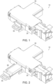
Fig. 1 shows a top perspective view of a latch strike mechanism according to one embodiment; -
Fig. 2 shows a top perspective view of a latch strike mechanism according to one embodiment; -
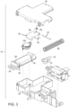
Fig. 3 shows an exploded perspective view of the latch strike mechanism shown inFig. 1 ; -
Fig. 4 shows an exploded perspective view of the latch strike mechanism shown inFig. 1 from the opposite side ofFig. 3 . -
Fig. 5 shows a top perspective view of the latch strike mechanism shown inFig. 1 , without a top portion of the housing; -
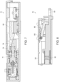
Fig. 6 shows a top view of the latch strike mechanism shown inFig. 5 ; -
Fig. 7 shows a rear cross-sectional view of the latch strike mechanism shown inFig. 1 taken along section 7-7 fromFig. 6 ; -
Fig. 8 shows a side cross-sectional view of the latch strike mechanism shown inFig. 1 taken along section 8-8 fromFig. 6 ; -
Fig. 9 shows a top perspective view of the latch strike mechanism shown inFig. 2 , without a top portion of the housing; -
Fig. 10 shows a side cross-sectional view of the latch strike mechanism shown inFig. 2 taken along section 10-10 fromFig. 9 ; -
Fig. 11 shows a perspective view of the latch strike mechanism shown inFig. 2 , without a top portion of the housing; -
Fig. 12 shows a top view of the latch strike mechanism shown inFig. 2 , without a top portion of the housing; -
Fig. 13 shows a rear cross-sectional view of the latch strike mechanism shown inFig. 2 taken along section 13-13 fromFig. 12 ; -
Fig. 14 shows a side cross-sectional view of the latch strike mechanism shown inFig. 2 taken along section 14-14 fromFig. 12 ; -
Fig. 15 shows a top view of a latch strike mechanism according to one embodiment; -
Fig. 16 shows a top view of a latch strike mechanism according to one embodiment; and -
Fig. 17 shows a schematic of a dishwasher using the subject latch strike mechanism. -
Figs. 1-16 show various embodiments and positions of alatch strike mechanism 10 for adishwasher 5. As described, the subjectlatch strike mechanism 10 is configured to improve drying performance by maintaining adishwasher door 7 in a slightly open position following a drying cycle.Fig. 17 shows a schematic of adishwasher 5 with adishwasher door 7 propped open by the subjectlatch strike mechanism 10. - The
latch strike mechanism 10 preferably includes ahousing 20 for accommodating the various internal components and for mounting to one of adishwasher tub 9 or adishwasher door 7. In a preferred embodiment thelatch strike mechanism 10 is mounted to thedishwasher tub 9 although it is contemplated that the assembly may be reversed for integration with thedishwasher door 7.Figs. 1 ,5 , and6 best show thelatch strike mechanism 10 in a closed, retracted position andFigs. 2 ,9 , and11 best show thelatch strike mechanism 10 in a fully open, extended position, as described in more detail herein. -
Figs. 3 and4 show exploded views of thelatch mechanism 10 according to one embodiment. Amoveable striker 50 is preferably projectable from thehousing 20 and is engageable with a door latch in thedishwasher door 7. Themoveable striker 50 is preferably configured to slide relative to thehousing 20 and more specifically may be slideably engaged with or within thehousing 20, such as along atrack 95. Thetrack 95 may be engageable with adamper gear 100 between a retracted and extended position. - The
moveable striker 50 is configured to extend relative to thedishwasher door 7, preferably in engagement with the door latch and/or another portion of thedishwasher door 7 to thereby maintain thedishwasher door 7 in a partially open position, as shown schematically inFig. 17 . A partially open position of the dishwasher door is defined as a position between fully closed and sealed relative to the dishwasher tub and fully open and thereby perpendicular to an open face of the dishwasher tub. By maintaining thedishwasher door 7 in a partially open position, thedishwasher tub 9 is vented to ambient conditions and thereby may effect a more complete drying of the dishes within the dishwasher either during the drying cycle or immediately after the drying cycle. - As such, the
moveable striker 50 is preferably used and configured to partially open thedishwasher door 7 while remaining latched and maintain thedishwasher door 7 in the partially open position. - In one embodiment of the
latch strike mechanism 10, themoveable striker 50 is configured to extend when a wash cycle of the dishwasher is complete. In an alternative embodiment, themoveable striker 50 is configured to extend when the drying cycle is started. In yet another embodiment, themoveable striker 50 is configured to extend when the drying cycle is completed. - As best shown between
Figs. 5 and11 , themoveable striker 50 may be connected with respect to aspring 90 within thehousing 20 and is slideable within thehousing 20 and spring-biased relative to thehousing 20. - As shown in
Figs. 3 and4 , thelatch strike mechanism 10 may further include anactuator 70 positioned within thehousing 20 and engageable with arelease plate 80. Theactuator 70 may include anactuator spring 72 as shown in cross-section inFigs. 7 and13 . In addition, theactuator 70 include awedge 75 that engages with therelease plate 80 to effect a desired rotation or pivot action. In one embodiment, thewedge 75 is engageable with aconical element 83 on therelease plate 80 to provide the desired pivoting action of therelease plate 80 relative to themoveable striker 50. - The
release plate 80 is positioned within thehousing 20 between the actuator 70 and themoveable striker 50. Therelease plate 80 may include aconical element 83 for engagement with thewedge 75 of theactuator 70. Additionally, therelease plate 80 may include anaxle 87 about which to pivot, as best shown inFigs. 3 and4 .Fig. 8 shows the engagement between therelease plate 80 and themoveable striker 50 in a closed, retracted position whileFig. 14 shows this engagement in the open, extended position. Theactuator 70 may be configured to actuate upon completion of the wash cycle, beginning of the drying cycle, or ending of the drying cycle. As shown in the figures, theactuator 70 may be positioned to extend and retract perpendicularly with respect to a direction of travel of themoveable striker 50. - The
actuator 70 preferably prevents rotation of therelease plate 80 in a retracted position, such as shown inFig. 8 , and permits rotation of therelease plate 80 in an extended position, as shown inFig. 14 . Following engagement by theactuator 70 with therelease plate 80, the rotation of therelease plate 80 relative to a plane of movement of themoveable striker 50 preferably releases thespring 90 to extend themoveable striker 50. This action is best shown fromFig. 8 to Fig. 14 . In this way, therelease plate 80 is pivotable between the retracted position and the extended position. Alternatively, or in addition, therelease plate 80 may be slideable between the retracted position and the extended position. As shown inFig. 8 and11 , arelease plate spring 85 is preferably positioned between thehousing 20 and therelease plate 80 to bias therelease plate 80 toward the retracted position. - As shown in
Figs. 3 and4 andFigs. 8 and14 , therelease plate 80 may include aleading edge 92 that engages with one of at least two curbs ordetents 55 positioned along a length of themoveable striker 50. The at least twodetents 55 are preferably located in a fully retracted, closed position of thelatch mechanism 10 and a fully extended, open position of thelatch mechanism 10. - According to preferred embodiments of the invention, the
actuator 70 may comprise a wax motor thermal actuator, solenoid, a motor, and/or a shape memory alloy. Theactuator 70 may be thermally actuated by a temperature, such as a desired or set temperature within a drying cycle. - According to one preferred embodiment of this invention, shown in
Figs. 1-14 , adamper gear 100 may be positioned relative to themoveable striker 50, specifically along thetrack 95 formed in or with respect to themoveable striker 50. Thedamper gear 100 is preferably configured to slow the extension of themoveable striker 50 along thetrack 95 relative to the bias force of thespring 90. In this way, thedishwasher door 7 may slowly, gradually, and in a measured manner open relative to the dishwasher tub as themoveable striker 50 slides to the extended, open position. - In one embodiment, an additional door position switch (not shown) may be configured to activate a tub light within the dishwasher tub or provide the dishwasher control with an additional level of safety.
- According to a preferred embodiment, the
latch strike mechanism 10 as described herein is configured to be reset when the dishwasher door is closed by a user. Specifically, themoveable striker 50 is configured slide to the retracted position thereby resettinglatch mechanism 10 and/or theactuator 70 by the act of closing the dishwasher door. - A corresponding method for operating the
latch strike mechanism 10 for a dishwasher door includes providing themoveable striker 50 projecting from thehousing 20 and engageable with the door latch. A subsequent sliding of themoveable striker 50 relative to thehousing 20 preferably extends against at least a portion of the dishwasher door to maintain the dishwasher door in a partially open position. - The subject method and sliding of the
moveable striker 50 may be activated by an actuator upon completion of a wash cycle and/or beginning and/or ending of the drying cycle whereby therelease plate 80 pivots with following contact from theactuator 70 to the extended position from the retracted position. Therelease plate 80 may pivot to release thespring 90 upon rotation of therelease plate 80 and thereby extend themoveable striker 50 relative to thehousing 20. - In one embodiment of the subject invention, the
spring 90 providing bias relative to the dishwasher door may be omitted due to the dishwasher gasket force and door counterbalance springs that are often present in conventional dishwashers. -
Figs. 15 and 16 show one alternative embodiment of the strike latch mechanism wherein astationary striker frame 30 preferably projects from thehousing 20 and is engageable with a door latch in the door. Amoveable striker 50 is preferably configured to slide relative to thestationary striker frame 30 and more specifically may be slideably engaged with or within thestationary striker frame 30. Themoveable striker 50 is configured to extend relative to the dishwasher door, preferably in engagement with the door latch and/or another portion of the dishwasher door to thereby maintain the dishwasher door in a partially open position. A partially open position of the dishwasher door is defined as a position between fully closed and sealed relative to the dishwasher tub and fully open and thereby perpendicular to an open face of the dishwasher tub. By maintaining the dishwasher door in a partially open position, the dishwasher tub is vented to ambient conditions and thereby may effect a more complete drying of the dishes within the dishwasher either during the drying cycle or immediately after the drying cycle. - As such, the
moveable striker 50 is preferably used and configured to partially open the dishwasher door while remaining latched and maintain the dishwasher door in the partially open position. The stationary striker frame is preferably used and configured to trigger an indicator switch of the latch. - As best shown between
Figs. 15 and 16 , in this embodiment, themoveable striker 50 may be connected with respect to aspring 90 within thehousing 20 and is slideable within thestationary striker frame 30 and spring-biased relative to thehousing 20. - The
actuator 70 in this embodiment preferably prevents rotation of therelease plate 80 in a retracted position, such as shown inFig. 15 , and permits rotation of therelease plate 80 in an extended position, as shown inFig. 16 . Unlike the rotation shown inFigs. 1-14 , therelease plate 80 in this embodiment rotates in a plane of movement of themoveable striker 50. Following engagement by theactuator 70 with therelease plate 80, the rotation of therelease plate 80 preferably releases thespring 90 to extend themoveable striker 50 relative to thestationary striker frame 30. This action is best shown fromFig. 15 to Fig. 16 . In this way, therelease plate 80 is pivotable between the retracted position and the extended position. Alternatively, or in addition, therelease plate 80 may be slideable between the retracted position and the extended position. As shown inFigs. 15 and 16 , in this embodiment, arelease plate spring 85 is preferably positioned between thehousing 20 and therelease plate 80 to bias therelease plate 80 toward the retracted position. - The invention illustratively disclosed herein suitably may be practiced in the absence of any element, part, step, component, or ingredient which is not specifically disclosed herein.
- While in the foregoing detailed description this invention has been described in relation to certain preferred embodiments thereof, and many details have been set forth for purposes of illustration, it will be apparent to those skilled in the art that the invention is susceptible to additional embodiments and that certain of the details described herein can be varied considerably without departing from the basic principles of the invention. Certain embodiments of the invention are described in the following clauses:
- Clause 1. A latch strike mechanism for a dishwasher door to improve drying performance, the latch mechanism comprising:
- a housing;
- a moveable striker slideably engaged with the housing, the moveable striker configured to extend to maintain the dishwasher door in a partially open position.
- Clause 2. The latch strike mechanism of Clause 1 wherein the moveable striker is configured to extend when a wash cycle of the dishwasher is complete.
- Clause 3. The latch strike mechanism of Clause 1 wherein the moveable striker is slideable within the housing along a track and spring biased relative to the housing.
- Clause 4. The latch strike mechanism of Clause 1 wherein the housing further comprises an actuator engageable with a release plate upon completion of a wash cycle.
-
Clause 5. The latch strike mechanism of Clause 4 wherein the actuator prevents movement of the release plate in a retracted position and permits movement of the release plate in an extended position. - Clause 6. The latch strike mechanism of
Clause 5 wherein the movement of the release plate releases a spring to extend the moveable striker relative to the stationary striker frame. -
Clause 7. The latch strike mechanism of Clause 4 wherein the release plate is at least one of pivotable and slideable between a retracted position and an extended position. -
Clause 8. The latch strike mechanism of Clause 4 wherein the actuator is thermally actuated by a temperature of a drying cycle. -
Clause 9. The latch strike mechanism of Clause 4 wherein the actuator comprises one of a wax motor thermal actuator, solenoid, motor, and shape memory alloy. -
Clause 10. The latch strike mechanism of Clause 1 further comprising a damper gear positioned relative to a track of the moveable striker and configured to slow the extension of the moveable striker relative to the housing. - Clause 11. The latch strike mechanism of Clause 1 further comprising an additional door position switch configured to activate a tub light or maintain product safety.
- Clause 12. The latch strike mechanism of Clause 1 wherein the actuator is positioned to extend and retract perpendicularly with respect to a travel of the moveable striker.
-
Clause 13. A method for operating a latch strike mechanism for a dishwasher door to improve drying performance, method comprising:- providing a housing with a moveable striker engageable with a door latch;
- sliding the moveable striker relative to the housing to extend the dishwasher door to maintain the dishwasher door in a partially open position, the moveable striker slideable between two detents.
-
Clause 14. The method ofClause 13 further comprising:- activating an actuator upon completion of a wash cycle; and
- moving a release plate with the actuator to an extended position, allowing translation of the moveable striker.
- Clause 15. The method of
Clause 14 further comprising:
moving the release plate upon activation of the actuator to the extended position from a retracted position, allowing translation of the moveable striker between the two detents. - Clause 16. The method of Clause 15 further comprising:
- releasing a spring upon rotation of the release plate; and
- extending the moveable striker relative to the stationary striker frame.
- Clause 17. The method of Clause 15 further comprising:
pivoting the release plate upon activation of the actuator to the extended position from a retracted position. - Clause 18. The method of Clause 15 further comprising:
sliding the release plate upon activation of the actuator to the extended position from a retracted position. - Clause 19. The method of
Clause 13 further comprising:
resetting the latch mechanism by manually closing the door. -
Clause 20. A latch strike mechanism for a dishwasher door to improve drying performance, the latch mechanism comprising:- a housing;
- a stationary striker frame projecting from the housing and engageable with a door latch;
- a moveable striker slideably engaged with the stationary striker frame, the moveable striker configured to extend to maintain the dishwasher door in a partially open position.
Claims (15)
- A latch strike mechanism for a dishwasher door to improve drying performance, the latch mechanism comprising:a housing;a moveable striker slideably engaged with the housing, the moveable striker configured to extend to maintain the dishwasher door in a partially open position.
- The latch strike mechanism of Claim 1 wherein the moveable striker is configured to extend when a wash cycle of the dishwasher is complete, or
wherein the moveable striker is slideable within the housing along a track and spring biased relative to the housing. - The latch strike mechanism of Claim 1 wherein the housing further comprises an actuator engageable with a release plate upon completion of a wash cycle.
- The latch strike mechanism of Claim 3 wherein the actuator prevents movement of the release plate in a retracted position and permits movement of the release plate in an extended position, and optionally
wherein the movement of the release plate releases a spring to extend the moveable striker relative to the stationary striker frame. - The latch strike mechanism of Claim 3 wherein the release plate is at least one of pivotable and slideable between a retracted position and an extended position.
- The latch strike mechanism of Claim 3 wherein the actuator is thermally actuated by a temperature of a drying cycle, or
wherein the actuator comprises one of a wax motor thermal actuator, solenoid, motor, and shape memory alloy. - The latch strike mechanism of Claim 1 further comprising a damper gear positioned relative to a track of the moveable striker and configured to slow the extension of the moveable striker relative to the housing.
- The latch strike mechanism of Claim 1 further comprising an additional door position switch configured to activate a tub light or maintain product safety, or
wherein the actuator is positioned to extend and retract perpendicularly with respect to a travel of the moveable striker. - A method for operating a latch strike mechanism for a dishwasher door to improve drying performance, method comprising:providing a housing with a moveable striker engageable with a door latch;sliding the moveable striker relative to the housing to extend the dishwasher door to maintain the dishwasher door in a partially open position, the moveable striker slideable between two detents.
- The method of Claim 9 further comprising:activating an actuator upon completion of a wash cycle; andmoving a release plate with the actuator to an extended position, allowing translation of the moveable striker.
- The method of Claim 10 further comprising:
moving the release plate upon activation of the actuator to the extended position from a retracted position, allowing translation of the moveable striker between the two detents. - The method of Claim 11 further comprising:releasing a spring upon rotation of the release plate; andextending the moveable striker relative to the stationary striker frame.
- The method of Claim 11 further comprising:pivoting the release plate upon activation of the actuator to the extended position from a retracted position, or the method further comprising:sliding the release plate upon activation of the actuator to the extended position from a retracted position.
- The method of Claim 9 further comprising:
resetting the latch mechanism by manually closing the door. - A latch strike mechanism for a dishwasher door to improve drying performance, the latch mechanism comprising:a housing;a stationary striker frame projecting from the housing and engageable with a door latch;a moveable striker slideably engaged with the stationary striker frame, the moveable striker configured to extend to maintain the dishwasher door in a partially open position.
Applications Claiming Priority (2)
| Application Number | Priority Date | Filing Date | Title |
|---|---|---|---|
| US202363534940P | 2023-08-28 | 2023-08-28 | |
| US18/815,079 US20250072707A1 (en) | 2023-08-28 | 2024-08-26 | Dishwasher door-opening striker |
Publications (1)
| Publication Number | Publication Date |
|---|---|
| EP4516197A1 true EP4516197A1 (en) | 2025-03-05 |
Family
ID=92593315
Family Applications (1)
| Application Number | Title | Priority Date | Filing Date |
|---|---|---|---|
| EP24197085.4A Pending EP4516197A1 (en) | 2023-08-28 | 2024-08-28 | Dishwasher door-opening striker |
Country Status (3)
| Country | Link |
|---|---|
| US (1) | US20250072707A1 (en) |
| EP (1) | EP4516197A1 (en) |
| CN (1) | CN119523381A (en) |
Citations (6)
| Publication number | Priority date | Publication date | Assignee | Title |
|---|---|---|---|---|
| EP0687439A1 (en) * | 1994-06-15 | 1995-12-20 | YMOS AKTIENGESELLSCHAFT Industrieprodukte | Dishwashing machine |
| FR2992157A1 (en) * | 2012-06-25 | 2013-12-27 | Fagorbrandt Sas | Dish washing and drying machine for use in home, has movable finger and movement transmission element cooperating together to move engaging element according to longitudinal movement when door is moved from closed to partly open position |
| FR2997283A1 (en) * | 2012-10-25 | 2014-05-02 | Fagorbrandt Sas | Machine for e.g. washing domestic dishes in home, has transmission element moved in rotation by actuator to make insertion element to perform longitudinal movement during displacement of door from closed position to half-opened position |
| US8882933B2 (en) * | 2008-06-02 | 2014-11-11 | Miele & Cie. Kg | Dishwasher having a device for opening the door in gaps |
| US20150028734A1 (en) * | 2012-02-13 | 2015-01-29 | Elbi International S.P.A. | Device for closing the door of a household appliance, in particular for a washing machine, such as a dishwasher |
| EP3307132B1 (en) * | 2015-06-10 | 2019-03-13 | ELBI International S.p.A. | System to control the closing of a door of a household appliance, in particular for a washing machine, such as a dishwasher |
Family Cites Families (13)
| Publication number | Priority date | Publication date | Assignee | Title |
|---|---|---|---|---|
| US7731806B2 (en) * | 2003-02-25 | 2010-06-08 | Illinois Tool Works, Inc. | Automatic door for dishwasher |
| DE102005028449B4 (en) * | 2005-06-17 | 2007-03-08 | Miele & Cie. Kg | Dishwasher with a washing container, which can be closed by a door, and method for performing a washing program in such a dishwasher |
| EP2394558B1 (en) * | 2010-05-12 | 2016-09-21 | Miele & Cie. KG | Washing machine, in particular domestic dishwasher, with an automatically opening door |
| WO2011141542A1 (en) * | 2010-05-14 | 2011-11-17 | Arcelik Anonim Sirketi | A dishwasher comprising an automatic door opening mechanism |
| ITTO20120642A1 (en) * | 2012-07-23 | 2014-01-24 | Elbi Int Spa | SYSTEM FOR CHECKING THE CLOSURE OF A DOOR OF A APPLIANCE APPLIANCES, IN PARTICULAR FOR A WASHING MACHINE, AS A DISHWASHER MACHINE. |
| US10422176B2 (en) * | 2012-12-07 | 2019-09-24 | Illinois Tool Works Inc. | Device for opening a door of a dishwasher |
| US9404287B2 (en) * | 2013-01-07 | 2016-08-02 | Haier Us Appliance Solutions, Inc. | System and method for determining appliance door status |
| KR102034091B1 (en) * | 2013-10-18 | 2019-11-08 | 삼성전자주식회사 | Dish washer |
| KR102124926B1 (en) * | 2015-11-30 | 2020-07-07 | 삼성전자주식회사 | Air blower and dish washer having the same |
| DE102016120593A1 (en) * | 2016-10-27 | 2018-05-03 | Hettich-Oni Gmbh & Co. Kg | Opening and closing system with an ejection device for a furniture and operating method for an opening and closing system |
| CN106761136B (en) * | 2016-12-27 | 2018-04-20 | 青岛海尔股份有限公司 | Automatic door operator and the refrigerator with the device |
| US10433702B2 (en) * | 2017-07-18 | 2019-10-08 | Haier Us Appliance Solutions, Inc. | Damped closure assembly for a dishwasher appliance |
| US12342976B2 (en) * | 2022-03-29 | 2025-07-01 | Midea Group Co., Ltd. | Exhibiting a dishwasher rack to the user |
-
2024
- 2024-08-26 US US18/815,079 patent/US20250072707A1/en active Pending
- 2024-08-27 CN CN202411180940.3A patent/CN119523381A/en active Pending
- 2024-08-28 EP EP24197085.4A patent/EP4516197A1/en active Pending
Patent Citations (6)
| Publication number | Priority date | Publication date | Assignee | Title |
|---|---|---|---|---|
| EP0687439A1 (en) * | 1994-06-15 | 1995-12-20 | YMOS AKTIENGESELLSCHAFT Industrieprodukte | Dishwashing machine |
| US8882933B2 (en) * | 2008-06-02 | 2014-11-11 | Miele & Cie. Kg | Dishwasher having a device for opening the door in gaps |
| US20150028734A1 (en) * | 2012-02-13 | 2015-01-29 | Elbi International S.P.A. | Device for closing the door of a household appliance, in particular for a washing machine, such as a dishwasher |
| FR2992157A1 (en) * | 2012-06-25 | 2013-12-27 | Fagorbrandt Sas | Dish washing and drying machine for use in home, has movable finger and movement transmission element cooperating together to move engaging element according to longitudinal movement when door is moved from closed to partly open position |
| FR2997283A1 (en) * | 2012-10-25 | 2014-05-02 | Fagorbrandt Sas | Machine for e.g. washing domestic dishes in home, has transmission element moved in rotation by actuator to make insertion element to perform longitudinal movement during displacement of door from closed position to half-opened position |
| EP3307132B1 (en) * | 2015-06-10 | 2019-03-13 | ELBI International S.p.A. | System to control the closing of a door of a household appliance, in particular for a washing machine, such as a dishwasher |
Also Published As
| Publication number | Publication date |
|---|---|
| US20250072707A1 (en) | 2025-03-06 |
| CN119523381A (en) | 2025-02-28 |
Similar Documents
| Publication | Publication Date | Title |
|---|---|---|
| CN113969719B (en) | An actuator with automatic door opening and closing function | |
| CN116517403A (en) | Door assembly of cooking utensil and cooking utensil | |
| CN116537650A (en) | Door assembly of cooking utensil and cooking utensil | |
| CN114165113A (en) | An effortless door lock device for closing the door | |
| US20250072707A1 (en) | Dishwasher door-opening striker | |
| WO2007129333A1 (en) | Oven withdoor equipped with push-pull device | |
| CN217106550U (en) | Door lock device capable of saving door closing force | |
| CN102395832A (en) | Door hinges for opening and closing doors of household appliances | |
| CN217681099U (en) | Automatic door closing mechanism and cooking utensil with same | |
| CN217039736U (en) | Cooking utensil | |
| CN215761116U (en) | Door opening and closing mechanism of double-door domestic oven with handle | |
| CN116624028A (en) | Door assemblies for cooking appliances and cooking appliances | |
| CN219795051U (en) | Double-door structure capable of realizing synchronous linkage opening and closing and oven with same | |
| CN209538826U (en) | A kind of cooking appliance door handle | |
| CN117231070B (en) | Automatic door closing mechanism and cooking utensil with same | |
| CN222184459U (en) | A movable door and window stopper | |
| CN221856495U (en) | Exquisite embedded hinge Embedded cabinet | |
| CN219910444U (en) | Household appliance | |
| CN222257576U (en) | Two-way door oven mechanism and industrial oven | |
| CN224093230U (en) | Door opening structure of push rod | |
| CN220869136U (en) | Loading assembly for sliding door device | |
| CN217361397U (en) | Safety module for controlling on-off of circuit and air fryer | |
| CN220439447U (en) | Lock catch structure and cooking equipment | |
| CN218457924U (en) | Door opening structure and cooking appliance | |
| CN219952966U (en) | Household appliance |
Legal Events
| Date | Code | Title | Description |
|---|---|---|---|
| PUAI | Public reference made under article 153(3) epc to a published international application that has entered the european phase |
Free format text: ORIGINAL CODE: 0009012 |
|
| STAA | Information on the status of an ep patent application or granted ep patent |
Free format text: STATUS: THE APPLICATION HAS BEEN PUBLISHED |
|
| AK | Designated contracting states |
Kind code of ref document: A1 Designated state(s): AL AT BE BG CH CY CZ DE DK EE ES FI FR GB GR HR HU IE IS IT LI LT LU LV MC ME MK MT NL NO PL PT RO RS SE SI SK SM TR |
|
| STAA | Information on the status of an ep patent application or granted ep patent |
Free format text: STATUS: REQUEST FOR EXAMINATION WAS MADE |
|
| 17P | Request for examination filed |
Effective date: 20250901 |