EP4516135A1 - Atomizer and aerosol generating device - Google Patents
Atomizer and aerosol generating device Download PDFInfo
- Publication number
- EP4516135A1 EP4516135A1 EP24191628.7A EP24191628A EP4516135A1 EP 4516135 A1 EP4516135 A1 EP 4516135A1 EP 24191628 A EP24191628 A EP 24191628A EP 4516135 A1 EP4516135 A1 EP 4516135A1
- Authority
- EP
- European Patent Office
- Prior art keywords
- aerosol generating
- generating substrate
- atomizer
- accommodating cavity
- aggregation area
- Prior art date
- Legal status (The legal status is an assumption and is not a legal conclusion. Google has not performed a legal analysis and makes no representation as to the accuracy of the status listed.)
- Pending
Links
Images

Classifications
-
- A—HUMAN NECESSITIES
- A24—TOBACCO; CIGARS; CIGARETTES; SIMULATED SMOKING DEVICES; SMOKERS' REQUISITES
- A24F—SMOKERS' REQUISITES; MATCH BOXES; SIMULATED SMOKING DEVICES
- A24F40/00—Electrically operated smoking devices; Component parts thereof; Manufacture thereof; Maintenance or testing thereof; Charging means specially adapted therefor
- A24F40/10—Devices using liquid inhalable precursors
-
- A—HUMAN NECESSITIES
- A24—TOBACCO; CIGARS; CIGARETTES; SIMULATED SMOKING DEVICES; SMOKERS' REQUISITES
- A24F—SMOKERS' REQUISITES; MATCH BOXES; SIMULATED SMOKING DEVICES
- A24F40/00—Electrically operated smoking devices; Component parts thereof; Manufacture thereof; Maintenance or testing thereof; Charging means specially adapted therefor
- A24F40/40—Constructional details, e.g. connection of cartridges and battery parts
-
- A—HUMAN NECESSITIES
- A24—TOBACCO; CIGARS; CIGARETTES; SIMULATED SMOKING DEVICES; SMOKERS' REQUISITES
- A24F—SMOKERS' REQUISITES; MATCH BOXES; SIMULATED SMOKING DEVICES
- A24F40/00—Electrically operated smoking devices; Component parts thereof; Manufacture thereof; Maintenance or testing thereof; Charging means specially adapted therefor
- A24F40/40—Constructional details, e.g. connection of cartridges and battery parts
- A24F40/48—Fluid transfer means, e.g. pumps
- A24F40/485—Valves; Apertures
-
- A—HUMAN NECESSITIES
- A24—TOBACCO; CIGARS; CIGARETTES; SIMULATED SMOKING DEVICES; SMOKERS' REQUISITES
- A24F—SMOKERS' REQUISITES; MATCH BOXES; SIMULATED SMOKING DEVICES
- A24F40/00—Electrically operated smoking devices; Component parts thereof; Manufacture thereof; Maintenance or testing thereof; Charging means specially adapted therefor
- A24F40/40—Constructional details, e.g. connection of cartridges and battery parts
- A24F40/44—Wicks
-
- A—HUMAN NECESSITIES
- A24—TOBACCO; CIGARS; CIGARETTES; SIMULATED SMOKING DEVICES; SMOKERS' REQUISITES
- A24F—SMOKERS' REQUISITES; MATCH BOXES; SIMULATED SMOKING DEVICES
- A24F40/00—Electrically operated smoking devices; Component parts thereof; Manufacture thereof; Maintenance or testing thereof; Charging means specially adapted therefor
- A24F40/40—Constructional details, e.g. connection of cartridges and battery parts
- A24F40/46—Shape or structure of electric heating means
Definitions
- an atomizer of an aerosol generating device can heat and atomize an aerosol generating substrate, such as e-liquid, stored in a liquid storage cavity to generate aerosols for a user to suck.
- the atomizer includes an atomization seat provided with an accommodating cavity and a heating member accommodated in the accommodating cavity.
- the aerosol generating substrate stored in the liquid storage cavity can enter the accommodating cavity to be heated and atomized by the heating member to generate the aerosols.
- the aerosols in the accommodating cavity will be accumulated in the accommodating cavity due to condensation, and the aerosol generating substrate accumulated in the accommodating cavity cannot be heated and atomized, resulting in a waste of the aerosol generating substrate and a low utilization rate.
- the atomizer in the embodiment of the present disclosure includes an atomization seat and a heating member.
- the atomization seat is provided with an accommodating cavity, and the heating member is disposed in the accommodating cavity.
- the atomizer further includes a liquid guide member located in the accommodating cavity and an aggregation area located in the accommodating cavity.
- the liquid guide member is connected to the heating member and extends into the aggregation area.
- the aggregation area is configured to aggregate an aerosol generating substrate.
- the liquid guide member is configured to guide the aerosol generating substrate that is aggregated in the aggregation area to flow back to the heating member.
- the liquid guide member is provided with at least one capillary groove in communication with the aggregation area, and a side wall of the capillary groove is configured to allow the aerosol generating substrate to flow along it to the heating member.
- the depth of the capillary groove is 0.3 mm to 1.0 mm.
- the width of the capillary groove is 0.3 mm to 0.8 mm.
- the distance between the side of the liquid guide member towards the aggregation area and the bottom of the aggregation area is 0 mm to 2.0 mm.
- the aggregation area is configured to block the aerosol generating substrate from flowing in a first direction, a second direction, and a third direction, the first direction, the second direction, and the third direction are all perpendicular to the central axis of the atomizer, the first direction is parallel to and opposite the second direction, and the first direction and the second direction are both perpendicular to the third direction.
- the aggregation area is configured to block the aerosol generating substrate from flowing in the first direction, the second direction, and a fourth direction, the fourth direction is perpendicular to the central axis of the atomizer, and the fourth direction is parallel to and opposite the third direction.
- the atomization seat includes at least one blocking member located in the accommodating cavity and configured to form the aggregation area.
- orientation or position relationships indicated by terms such as “center”, “longitudinal”, “transverse”, “length”, “width”, “thickness”, “upper”, “lower”, “front”, “rear”, “left”, “right”, “vertical”, “horizontal”, “top”, “bottom”, “inner”, “outer”, “clockwise”, “counterclockwise”, “axial”, “radial”, “circumferential” are orientation or position relationship shown based on the accompanying drawings, and are merely used to facilitate describing the present disclosure and simplifying the description, rather than indicating or implying that the mentioned device or element should have a particular orientation or be constructed and operated in a particular orientation, and therefore, should not be construed as a limitation to the present disclosure.
- first and second are used merely for the purpose of description and shall not be construed as indicating or implying relative importance or implying a quantity of indicated technical features. Therefore, a feature restricted by “first” or “second” may explicitly indicate or implicitly include at least one of such features.
- a plurality of means at least two, such as two, three, etc., unless otherwise specified.
- connection may be a fixed connection, a detachable connection, or an integral connection; or the connection may be a mechanical connection or may be an electrical connection; or the connection may be a direct connection, an indirect connection through an intermediate, or internal communication between two elements or an interaction relationship between two elements, unless otherwise specified.
- connection may be a fixed connection, a detachable connection, or an integral connection; or the connection may be a mechanical connection or may be an electrical connection; or the connection may be a direct connection, an indirect connection through an intermediate, or internal communication between two elements or an interaction relationship between two elements, unless otherwise specified.
- first feature and the second feature may be in direct contact, or in indirect contact through an intermediate media.
- first feature when the first feature is “above” the second feature, it may be that the first feature is directly above or obliquely above the second feature, or merely indicates that the horizontal height of the first feature is higher than that of the second feature.
- first feature when the first feature is "below” the second feature, it may be that the first feature is directly below or obliquely below the second feature, or merely indicates that the horizontal height of the first feature is less than that of the second feature.
- an atomizer in an aerosol generating device can heat and atomize an aerosol generating substrate stored, such as e-liquid, in a liquid storage cavity to generate aerosols for a user to suck.
- the atomizer includes an atomization seat provided with an accommodating cavity and a heating member accommodated in the accommodating cavity.
- the aerosol generating substrate stored in the liquid storage cavity can enter the accommodating cavity to be heated and atomized by the heating member to generate the aerosols.
- the aerosols in the accommodating cavity will be accumulated in the accommodating cavity due to condensation, and the aerosol generating substrate accumulated in the accommodating cavity cannot be heated and atomized, resulting in a waste of the aerosol generating substrate and a low utilization rate.
- the embodiment of the present disclosure provides an atomizer 10 and an aerosol generating device 100.
- the atomizer 10 in the embodiment of the present disclosure includes an atomization seat 11 and a heating member 13.
- the atomization seat 11 is provided with an accommodating cavity 101, and the heating member 13 is disposed in the accommodating cavity 101.
- the atomizer 10 further includes a liquid guide member 111 located in the accommodating cavity 101 and an aggregation area 112 located inside the accommodating cavity 101.
- the liquid guide member 111 is connected to the heating member 13, and the liquid guide member 111 extends into the aggregation area 112.
- the aggregation area 112 is configured to aggregate the aerosol generating substrate 200 (as shown in FIG. 9 ).
- the liquid guide member 111 is configured to guide the aerosol generating substrate 200 gathered in the aggregation area 112 to flow back to the heating member 13.
- the aerosol generating substrate 200 is an item capable of generating aerosols. Specifically, the aerosol generating substrate 200 can form fine particles by heating or ultrasonic oscillation, and the fine particles are mixed with air to form aerosols.
- the form of the aerosol generating substrate 200 may be solid or liquid.
- the aerosol generating substrate 200 may be e-liquid, wherein the e-liquid is a mixed liquid dissolved in substances such as nicotine, and its solute is a common organic and/or a common inorganic solutes such as propylene glycol, plant glycerol, and pure water.
- the aerosol may be visible or invisible and may include a vapor (such as a fine particulate matter in a gaseous state, which is typically liquid or solid at room temperature) and a liquid droplet of gas and condensed vapor.
- a vapor such as a fine particulate matter in a gaseous state, which is typically liquid or solid at room temperature
- a liquid droplet of gas and condensed vapor a liquid droplet of gas and condensed vapor.
- aerosol used in the disclosure encompasses the aerosol generated during the heating of the aerosol generating substrate 200 in the aerosol generating device 100 of a heating type.
- the heating member 13 is a device or a material that can generate heat energy and transfer the heat energy to the surrounding environment.
- the heating member 13 may include a porous ceramic 131, a heating layer 133, and conductive members 135.
- the porous ceramic 131 is accommodated in the accommodating cavity 101, and the heating layer 133 is disposed on one side of the porous ceramic 131 and electrically connected to the conductive members 135, such that the heating layer 133 can heat and atomize the aerosol generating substrate 200 that enters the accommodating cavity 101 and is adsorbed by the porous ceramic 131.
- the porous ceramic 131 is usually prepared by mixing a ceramic slurry with a pore-forming agent and then sintering, and the sintered ceramic body has a large number of micropores (not shown in the figure).
- the heating layer 133 may be a heating circuit, a heating film, a heating sheet, a heating wire, or a heating net, etc., which is not limited herein.
- the conductive member 135 may be an electrode, wherein the electrode may be in a sheet shape, a columnar shape, or a powder porous shape, etc., which is not limited herein.
- the liquid guide member 111 is connected to the porous ceramic 131 and located in the accommodating cavity 101, and the liquid guide member 111 extends into the aggregation area 112 to guide the aerosol generating substrate 200 in the aggregation area 112 to flow back to the porous ceramic 131, thereby avoiding the waste caused by the accumulation of the aerosol generating substrate 200 in the aggregation area 112.
- the number of the liquid guide member 111 may be one, and the one liquid guide member 111 is connected to any position of the heating member 13.
- the user can control the aerosol generating substrate 200 in the accommodating cavity 101 to be accumulated as much as possible at the position where the liquid guide member 111 is located.
- the user can control the angle at which the aerosol generating device 100 is tilted when being sucked, so that the aerosol generating substrate 200 can be accumulated in the aggregation area 112 as much as possible, so that the liquid guide member 111 can guide the aerosol generating substrate 200 in the aggregation area 112 to flow back to the heating member 13, and the heating member 13 can re-heat the reflowed aerosol generating substrate 200, so that the waste of the aerosol generating substrate 200 can be reduced and on the other hand, compared with the aerosol generating substrate 200 in the accommodating cavity 101 being only partially located or completely not located at the position where the liquid guide member 111 is located, the backflow efficiency of the aerosol generating substrate 200 can also improved.
- the one liquid guide member 111 may be arranged around the heating member 13, so that the aerosol generating substrate 200 in the accommodating cavity 101 can be in contact with the liquid guide member 111 regardless of the inclination of the aerosol generating device 100 (as shown in FIG. 1 ) in any direction, to ensure that the aerosol generating substrate 200 can quickly flow back to the heating member 13, thereby improving the backflow efficiency of the aerosol generating substrate 200.
- a plurality of liquid guide members 111 may be provided, and the plurality of liquid guide members 111 are evenly spaced around the heating member 13.
- the number of the liquid guide members 111 may be four, and the four liquid guide members 111 are uniformly connected to the four side walls 1163 of the heating member 13.
- the arrangement of the plurality of liquid guide members 111 can enable the aerosol generating substrate 200 in the accommodating cavity 101 to be in contact with at least part of the liquid guide members 111 regardless of the inclination of the aerosol generating device 100 (as shown in FIG. 1 ) in any direction, thereby ensuring that the aerosol generating substrate 200 can quickly flow back to the heating member 13, and improving the backflow efficiency of the aerosol generating substrate 200.
- the atomizer 10 in the embodiments of the present disclosure, includes the liquid guide member 111 located in the accommodating cavity 101 and the aggregation area 112 located in the accommodating cavity 101, the liquid guide member 111 is connected to the heating member 13, and the liquid guide member 111 extends into the aggregation area 112.
- the liquid guide member 111 can guide the aerosol generating substrate 200 gathered in the aggregation area 112 to flow back to the heating member 13.
- the heating member 13 can heat and atomize the aerosol generating substrate 200 that is reflowed, thereby avoiding the waste caused by the accumulation of the aerosol generating substrate 200 in the accommodating cavity 101, and improving the utilization rate of the aerosol generating substrate 200.
- the atomizer 10 is further described below in conjunction with the accompanying drawings.
- the atomization seat 11 includes a top cover 115 and a base 116
- the top cover 115 includes a top wall 1151 and a peripheral wall 1153 extending from the periphery of the top wall 1151 towards the direction of the base 116.
- the base 116 includes a bottom wall 1161 and a side wall 1163 extending from the periphery of the bottom wall 1161 towards the direction of the top cover 115.
- the side wall 1163 of the base 116 is connected to the peripheral wall 1153 of the top cover 115.
- a connecting member 1155 is provided on the peripheral wall 1153 of the top cover 115, a fitting member 1165 is provided on the side wall 1163 of the base 116, and the connecting member 1155 cooperates with the fitting member 1165 to achieve the connection between the base 116 and the top cover 115.
- the connecting member 1155 may be a protrusion that extends from the peripheral wall 1153 of the top cover 115 in the direction away from the top cover 115
- the fitting member 1165 may be a groove that is recessed in the direction away from the center of the accommodating cavity 101 from the inner side of the side wall 1163 of the base 116 (i.e., the side of the side wall 1163 facing the accommodating cavity 101), and the protrusion can extend into the groove to achieve the connection between the base 116 and the top cover 115.
- one end of the first sub-portion 1131 may be connected to the peripheral wall 110 of the atomization seat 11, that is, the first end of the first sub-portion 1131 may be connected to the peripheral wall 110 of the atomization seat 11.
- a partial structure of the peripheral wall 110 of the atomization seat 11 can be the second sub-portion 1133.
- the first sub-portion 1131, the second sub-portion 1133, and the peripheral wall 110 of the atomization seat 11 jointly form the aggregation area 112 to block the flow of the aerosol generating substrate 200 in the first direction X, the second direction Y, and the fourth direction N.
Landscapes
- Special Spraying Apparatus (AREA)
- Disinfection, Sterilisation Or Deodorisation Of Air (AREA)
Abstract
Description
- The present disclosure relates to the field of atomization technology, and more specifically, relates to an atomizer and an aerosol generating device.
- At present, an atomizer of an aerosol generating device can heat and atomize an aerosol generating substrate, such as e-liquid, stored in a liquid storage cavity to generate aerosols for a user to suck. Generally, the atomizer includes an atomization seat provided with an accommodating cavity and a heating member accommodated in the accommodating cavity. The aerosol generating substrate stored in the liquid storage cavity can enter the accommodating cavity to be heated and atomized by the heating member to generate the aerosols. However, the aerosols in the accommodating cavity will be accumulated in the accommodating cavity due to condensation, and the aerosol generating substrate accumulated in the accommodating cavity cannot be heated and atomized, resulting in a waste of the aerosol generating substrate and a low utilization rate.
- An embodiment of the present disclosure provides an atomizer and an aerosol generating device.
- The atomizer in the embodiment of the present disclosure includes an atomization seat and a heating member. The atomization seat is provided with an accommodating cavity, and the heating member is disposed in the accommodating cavity. The atomizer further includes a liquid guide member located in the accommodating cavity and an aggregation area located in the accommodating cavity. The liquid guide member is connected to the heating member and extends into the aggregation area. The aggregation area is configured to aggregate an aerosol generating substrate. When the aerosol generating substrate enters the accommodating cavity, the liquid guide member is configured to guide the aerosol generating substrate that is aggregated in the aggregation area to flow back to the heating member.
- In some embodiments, the liquid guide member is provided with at least one capillary groove in communication with the aggregation area, and a side wall of the capillary groove is configured to allow the aerosol generating substrate to flow along it to the heating member.
- In some embodiments, the depth of the capillary groove is 0.3 mm to 1.0 mm.
- In some embodiments, the width of the capillary groove is 0.3 mm to 0.8 mm.
- In some embodiments, the distance between the side of the liquid guide member towards the aggregation area and the bottom of the aggregation area is 0 mm to 2.0 mm.
- In some embodiments, the aggregation area is configured to block the aerosol generating substrate from flowing in a first direction, a second direction, and a third direction, the first direction, the second direction, and the third direction are all perpendicular to the central axis of the atomizer, the first direction is parallel to and opposite the second direction, and the first direction and the second direction are both perpendicular to the third direction.
- In some embodiments, the aggregation area is configured to block the aerosol generating substrate from flowing in the first direction, the second direction, and a fourth direction, the fourth direction is perpendicular to the central axis of the atomizer, and the fourth direction is parallel to and opposite the third direction.
- In some embodiments, the atomization seat includes at least one blocking member located in the accommodating cavity and configured to form the aggregation area.
- In some embodiments, the aggregation area is further configured to block the aerosol generating substrate from flowing in a fourth direction, the fourth direction is perpendicular to the central axis of the atomizer, and the fourth direction is parallel to and opposite the third direction.
- In some embodiments, the atomization seat further includes a liquid storage groove located in the accommodating cavity, the liquid storage groove is in communication with the aggregation area and configured to store the aerosol generating substrate in the accommodating cavity.
- An aerosol generating device in the embodiment of the present disclosure includes a battery assembly and the atomizer of any one of the above embodiments, wherein the atomizer is electrically connected to the battery assembly.
- In the atomizer and the aerosol generating device in the embodiments of the present disclosure, the atomizer includes the liquid guide member located in the accommodating cavity and an aggregation area located in the accommodating cavity, the liquid guide member is connected to the heating member and extends into the aggregation area, and the liquid guide member can guide the aerosol generating substrate aggregated in the aggregation area to flow back to the heating member, and the heating member can heat and atomize the aerosol generating substrate that is back flowed, thereby avoiding the waste caused by accumulation of the aerosol generating substrate in the accommodating cavity, thereby improving the utilization rate of the aerosol generating substrate.
- The additional aspects and advantages of the present disclosure will be partially provided in the following description, partially will become apparent from the following description, or will be learned through the practice of the present disclosure.
- The above and/or additional aspects and advantages of the present disclosure will become apparent and easily understood from the description of the embodiments in conjunction with the accompanying drawings, wherein:
-
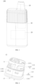
FIG. 1 is a schematic structural diagram of an aerosol generating device in some embodiments of the present disclosure; -
FIG. 2 is a schematic structural diagram of an implementation of an atomizer in the aerosol generating device shown inFIG. 1 ; -
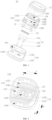
FIG. 3 is an exploded schematic diagram of the atomizer shown inFIG. 2 ; -
FIG. 4 is a schematic structural diagram of a partial structure of an atomization seat in the atomizer shown inFIG. 3 ; -
FIG. 5 is a schematic structural diagram of a partial structure of the atomization seat in the atomizer shown inFIG. 3 ; -
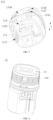
FIG. 6 is a schematic structural diagram of another implementation of the atomizer in the aerosol generating device shown inFIG. 1 ; -
FIG. 7 is an exploded schematic diagram of the atomizer shown inFIG. 6 ; -
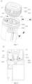
FIG. 8 is a sectional schematic diagram of the atomizer shown inFIG. 6 ; and -
FIG. 9 is a sectional schematic diagram of the aerosol generating device in some embodiments of the present disclosure. - Description of numerals of main components:
- aerosol
generating device 100;aerosol generating substrate 200; -
atomizer 10; accommodatingcavity 101,first side 1011 of bottom of accommodating cavity,second side 1013 of bottom of accommodating cavity;battery assembly 20;suction member 30,suction channel 31,liquid storage cavity 33; detectingmember 40; -
atomization seat 11,liquid guide member 111,capillary groove 1111,aggregation area 112,blocking member 113,first sub-portion 1131,second sub-portion 1133,liquid storage groove 114,top cover 115,top wall 1151,peripheral wall 1153, connectingmember 1155,first opening 1157,second opening 1158, communicatinggroove 1159,base 116,bottom wall 1161,side wall 1163,fitting member 1165,air inlet hole 1167,first aggregation member 117, firstliquid aggregating groove 1171,second aggregation member 118, secondliquid aggregating groove 1181,air outlet channel 119,first end 1191,second end 1193; -
heating member 13, porous ceramic 131,heating layer 133,conductive member 135;first seal 15;second seal 17. - In order to make the above objectives, features, and advantages of the present disclosure clearer and more comprehensible, specific embodiments of the present disclosure are described in detail below with reference to the accompanying drawings. Many specific details are elaborated in the following description to facilitate a thorough understanding of the present disclosure. However, the present disclosure can be implemented in many ways different from those described herein, and a person skilled in the art can make similar improvements without departing from the connotation of the present disclosure, and therefore, the present disclosure is not limited by the specific embodiments disclosed below.
- In the description of the present disclosure, it should be understood that that, orientation or position relationships indicated by terms such as "center", "longitudinal", "transverse", "length", "width", "thickness", "upper", "lower", "front", "rear", "left", "right", "vertical", "horizontal", "top", "bottom", "inner", "outer", "clockwise", "counterclockwise", "axial", "radial", "circumferential" are orientation or position relationship shown based on the accompanying drawings, and are merely used to facilitate describing the present disclosure and simplifying the description, rather than indicating or implying that the mentioned device or element should have a particular orientation or be constructed and operated in a particular orientation, and therefore, should not be construed as a limitation to the present disclosure.
- In addition, terms "first" and "second" are used merely for the purpose of description and shall not be construed as indicating or implying relative importance or implying a quantity of indicated technical features. Therefore, a feature restricted by "first" or "second" may explicitly indicate or implicitly include at least one of such features. In the description of the present disclosure, "a plurality of" means at least two, such as two, three, etc., unless otherwise specified.
- In the present disclosure, unless otherwise explicitly specified and defined, terms such as "mounted", "connected", "connection", " fixed" should be understood in a broad sense. For example, the connection may be a fixed connection, a detachable connection, or an integral connection; or the connection may be a mechanical connection or may be an electrical connection; or the connection may be a direct connection, an indirect connection through an intermediate, or internal communication between two elements or an interaction relationship between two elements, unless otherwise specified. For a person skilled in the art, the specific meanings of the above terms in the present disclosure can be understood based on specific circumstances.
- In the present disclosure, unless otherwise explicitly specified and defined, when a first feature is referred to as being "above" or "below" a second feature, the first feature and the second feature may be in direct contact, or in indirect contact through an intermediate media. Moreover, when the first feature is "above" the second feature, it may be that the first feature is directly above or obliquely above the second feature, or merely indicates that the horizontal height of the first feature is higher than that of the second feature. When the first feature is "below" the second feature, it may be that the first feature is directly below or obliquely below the second feature, or merely indicates that the horizontal height of the first feature is less than that of the second feature.
- It should be noted that, when an element is referred to as being "fixed to" or "disposed on" another element, it may be directly on another element or there may be an intervening element. When an element is considered to be "connected" to another element, it may be directly connected to another element or there may be an intervening element present simultaneously. The terms "vertical", "horizontal", "upper", "lower", "left", "right" and the like used in the disclosure are for illustrative purposes only and are not intended to be the only embodiments.
- At present, an atomizer in an aerosol generating device can heat and atomize an aerosol generating substrate stored, such as e-liquid, in a liquid storage cavity to generate aerosols for a user to suck. Generally, the atomizer includes an atomization seat provided with an accommodating cavity and a heating member accommodated in the accommodating cavity. The aerosol generating substrate stored in the liquid storage cavity can enter the accommodating cavity to be heated and atomized by the heating member to generate the aerosols. However, the aerosols in the accommodating cavity will be accumulated in the accommodating cavity due to condensation, and the aerosol generating substrate accumulated in the accommodating cavity cannot be heated and atomized, resulting in a waste of the aerosol generating substrate and a low utilization rate. In order to solve this problem, please refer to
FIG. 1 and FIG. 2 , the embodiment of the present disclosure provides anatomizer 10 and anaerosol generating device 100. - Please refer to
FIG. 1 and FIG. 2 orFIG. 8 , theatomizer 10 in the embodiment of the present disclosure includes anatomization seat 11 and aheating member 13. Theatomization seat 11 is provided with anaccommodating cavity 101, and theheating member 13 is disposed in theaccommodating cavity 101. Theatomizer 10 further includes aliquid guide member 111 located in theaccommodating cavity 101 and anaggregation area 112 located inside theaccommodating cavity 101. Theliquid guide member 111 is connected to theheating member 13, and theliquid guide member 111 extends into theaggregation area 112. Theaggregation area 112 is configured to aggregate the aerosol generating substrate 200 (as shown inFIG. 9 ). When theaerosol generating substrate 200 enters theaccommodating cavity 101, theliquid guide member 111 is configured to guide theaerosol generating substrate 200 gathered in theaggregation area 112 to flow back to theheating member 13. - The
aerosol generating substrate 200 is an item capable of generating aerosols. Specifically, theaerosol generating substrate 200 can form fine particles by heating or ultrasonic oscillation, and the fine particles are mixed with air to form aerosols. The form of theaerosol generating substrate 200 may be solid or liquid. In the present disclosure, theaerosol generating substrate 200 may be e-liquid, wherein the e-liquid is a mixed liquid dissolved in substances such as nicotine, and its solute is a common organic and/or a common inorganic solutes such as propylene glycol, plant glycerol, and pure water. The aerosol may be visible or invisible and may include a vapor (such as a fine particulate matter in a gaseous state, which is typically liquid or solid at room temperature) and a liquid droplet of gas and condensed vapor. The term "aerosol" used in the disclosure encompasses the aerosol generated during the heating of theaerosol generating substrate 200 in theaerosol generating device 100 of a heating type. - The
heating member 13 is a device or a material that can generate heat energy and transfer the heat energy to the surrounding environment. Please refer toFIG. 3 , in some embodiments, theheating member 13 may include a porous ceramic 131, aheating layer 133, andconductive members 135. Wherein, the porous ceramic 131 is accommodated in theaccommodating cavity 101, and theheating layer 133 is disposed on one side of the porous ceramic 131 and electrically connected to theconductive members 135, such that theheating layer 133 can heat and atomize theaerosol generating substrate 200 that enters theaccommodating cavity 101 and is adsorbed by theporous ceramic 131. It should be noted that in some embodiments, the porous ceramic 131 is usually prepared by mixing a ceramic slurry with a pore-forming agent and then sintering, and the sintered ceramic body has a large number of micropores (not shown in the figure). Theheating layer 133 may be a heating circuit, a heating film, a heating sheet, a heating wire, or a heating net, etc., which is not limited herein. Theconductive member 135 may be an electrode, wherein the electrode may be in a sheet shape, a columnar shape, or a powder porous shape, etc., which is not limited herein. - In the present disclosure, the
liquid guide member 111 is connected to the porous ceramic 131 and located in theaccommodating cavity 101, and theliquid guide member 111 extends into theaggregation area 112 to guide theaerosol generating substrate 200 in theaggregation area 112 to flow back to the porous ceramic 131, thereby avoiding the waste caused by the accumulation of theaerosol generating substrate 200 in theaggregation area 112. - In some embodiments, the number of the
liquid guide member 111 may be one, and the oneliquid guide member 111 is connected to any position of theheating member 13. In the case that the aerosols are accumulated in theaccommodating cavity 101 due to condensation, the user can control theaerosol generating substrate 200 in theaccommodating cavity 101 to be accumulated as much as possible at the position where theliquid guide member 111 is located. For example, the user can control the angle at which theaerosol generating device 100 is tilted when being sucked, so that theaerosol generating substrate 200 can be accumulated in theaggregation area 112 as much as possible, so that theliquid guide member 111 can guide theaerosol generating substrate 200 in theaggregation area 112 to flow back to theheating member 13, and theheating member 13 can re-heat the reflowedaerosol generating substrate 200, so that the waste of theaerosol generating substrate 200 can be reduced and on the other hand, compared with theaerosol generating substrate 200 in theaccommodating cavity 101 being only partially located or completely not located at the position where theliquid guide member 111 is located, the backflow efficiency of theaerosol generating substrate 200 can also improved. It can be understood that in some embodiments, the oneliquid guide member 111 may be arranged around theheating member 13, so that theaerosol generating substrate 200 in theaccommodating cavity 101 can be in contact with theliquid guide member 111 regardless of the inclination of the aerosol generating device 100 (as shown inFIG. 1 ) in any direction, to ensure that theaerosol generating substrate 200 can quickly flow back to theheating member 13, thereby improving the backflow efficiency of theaerosol generating substrate 200. - In some other embodiments, a plurality of
liquid guide members 111 may be provided, and the plurality ofliquid guide members 111 are evenly spaced around theheating member 13. For example, in the case that the cross-sectional shape of theheating member 13 is quadrilateral, the number of theliquid guide members 111 may be four, and the fourliquid guide members 111 are uniformly connected to the fourside walls 1163 of theheating member 13. The arrangement of the plurality ofliquid guide members 111 can enable theaerosol generating substrate 200 in theaccommodating cavity 101 to be in contact with at least part of theliquid guide members 111 regardless of the inclination of the aerosol generating device 100 (as shown inFIG. 1 ) in any direction, thereby ensuring that theaerosol generating substrate 200 can quickly flow back to theheating member 13, and improving the backflow efficiency of theaerosol generating substrate 200. - In the
atomizer 10 in the embodiments of the present disclosure, theatomizer 10 includes theliquid guide member 111 located in theaccommodating cavity 101 and theaggregation area 112 located in theaccommodating cavity 101, theliquid guide member 111 is connected to theheating member 13, and theliquid guide member 111 extends into theaggregation area 112. Theliquid guide member 111 can guide theaerosol generating substrate 200 gathered in theaggregation area 112 to flow back to theheating member 13. Theheating member 13 can heat and atomize theaerosol generating substrate 200 that is reflowed, thereby avoiding the waste caused by the accumulation of theaerosol generating substrate 200 in theaccommodating cavity 101, and improving the utilization rate of theaerosol generating substrate 200. - The
atomizer 10 is further described below in conjunction with the accompanying drawings. - Please refer to
FIG. 2 orFIG. 7 , in some embodiments, theatomization seat 11 includes atop cover 115 and abase 116, and thetop cover 115 includes atop wall 1151 and aperipheral wall 1153 extending from the periphery of thetop wall 1151 towards the direction of thebase 116. Thebase 116 includes abottom wall 1161 and aside wall 1163 extending from the periphery of thebottom wall 1161 towards the direction of thetop cover 115. Theside wall 1163 of thebase 116 is connected to theperipheral wall 1153 of thetop cover 115. - Specifically, in some embodiments, a connecting
member 1155 is provided on theperipheral wall 1153 of thetop cover 115, afitting member 1165 is provided on theside wall 1163 of thebase 116, and the connectingmember 1155 cooperates with thefitting member 1165 to achieve the connection between the base 116 and thetop cover 115. Wherein, the connectingmember 1155 may be a protrusion that extends from theperipheral wall 1153 of thetop cover 115 in the direction away from thetop cover 115, and thefitting member 1165 may be a groove that is recessed in the direction away from the center of theaccommodating cavity 101 from the inner side of theside wall 1163 of the base 116 (i.e., the side of theside wall 1163 facing the accommodating cavity 101), and the protrusion can extend into the groove to achieve the connection between the base 116 and thetop cover 115. Of course, it may also be that the connectingmember 1155 is a groove that is recessed towards the center of theaccommodating cavity 101 from the outer side of theperipheral wall 1153 of thetop cover 115, and thefitting member 1165 is a protrusion that extends from theside wall 1163 of the base 116 towards the center of theaccommodating cavity 101, and the protrusion can extend into the groove to achieve the connection between the base 116 and thetop cover 115. It can be understood that in other embodiments, theside wall 1163 of thebase 116 and theperipheral wall 1153 of thetop cover 115 may also be connected in a connection manner such as bonding, threaded connection, or welding, which is not limited herein. In the present disclosure, thetop cover 115 and the base 116 can be integrally formed, and in this case, theperipheral wall 1153 of thetop cover 115 and theside wall 1163 of the base 116 jointly form aperipheral wall 110 of theatomization seat 11. - Please refer to
FIG. 4 , generally, theaerosol generating substrate 200 can be accumulated at the bottom of the accommodating cavity 101 (i.e. thebottom wall 1161 of the base 116). If the bottom of theaccommodating cavity 101 is not provided with a blockingmember 113, theaerosol generating substrate 200 can flow freely in theaccommodating cavity 101, and theaerosol generating substrate 200 will all flow to one side of the base 116 when theaerosol generating device 100 is inclined, resulting in a smaller contact area between part of theliquid guide members 111 and theaerosol generating substrate 200, thereby affecting the backflow efficiency of theaerosol generating substrate 200. In some embodiments, thebase 116 may include at least one blockingmember 113 located in theaccommodating cavity 101 and configured to form theaggregation area 112, and theliquid guide member 111 extends into theaggregation area 112. Due to the arrangement of the blockingmember 113, when theaerosol generating device 100 is inclined, theaerosol generating substrate 200 can be accumulated in theaggregation area 112 instead of being accumulated on one side of thebase 116, thereby ensuring the contact area between theaerosol generating substrate 200 and theliquid guide member 111, and improving the backflow efficiency of theaerosol generating substrate 200. Specifically, in some embodiments, the blockingmember 113 may extend from thebottom wall 1161 of the base 116 towards thetop cover 115. Wherein, the blockingmember 113 may be disposed at any position on thebottom wall 1161 of thebase 116. It should be noted that the cross-sectional shape of the blockingmember 113 may be a regular shape such as an L shape or a linear shape, or may be an irregular shape. - Please refer to
FIG. 2 to FIG. 4 , in some embodiments, theaggregation area 112 can block the flow of the aerosol generating substrate 200 (as shown inFIG. 9 ) from a first direction X, a second direction Y, and a third direction M. The first direction X, the second direction Y, and the third direction M are all perpendicular to the central axis of theatomizer 10, the first direction X is parallel to and opposite the second direction Y, and the first direction X and the second direction Y are both perpendicular to the third direction M. - Specifically, in some embodiments, when the blocking
member 113 forms theaggregation area 112, the blockingmember 113 can block the flow of theaerosol generating substrate 200 in the first direction X, the second direction Y, and the third direction M. Therefore, theaerosol generating substrate 200 in theaccommodating cavity 101 can be aggregated in theaggregation area 112 as much as possible, which not only facilitates the guiding of theaerosol generating substrate 200 in theaggregation area 112 back to theheating member 13 by theliquid guide member 111, reduces the waste of theaerosol generating substrate 200, but also improves the backflow efficiency of theaerosol generating substrate 200. It should be noted that in this embodiment, the number of theaggregation area 112 may only be one, and in this case, the blockingmember 113 may include afirst sub-portion 1131 andsecond sub-portions 1133 extending from two opposite ends of thefirst sub-portion 1131, wherein the second sub-portions 1133 extend from the two opposite ends of thefirst sub-portion 1131 towards theperipheral wall 110 of theatomization seat 11. In some embodiments, the extension direction of thefirst sub-portion 1131 may be substantially the same as the first direction X, and the extension direction of thesecond sub-portion 1133 may be substantially the same as a fourth direction N (wherein the fourth direction N is parallel to and opposite the third direction M), so that thefirst sub-portion 1131 and the twosecond sub-portions 1133 jointly form theaggregation area 112 to block theaerosol generating substrate 200 from flowing in the first direction X, the second direction Y, and the third direction M. - It can be understood that in other embodiments, one end of the
first sub-portion 1131 may be connected to the peripheral wall 220 of theatomization seat 11, that is, a first end of thefirst sub-portion 1131 may be connected to theperipheral wall 110 of theatomization seat 11. In this case, a partial structure of theperipheral wall 110 of theatomization seat 11 can be thesecond sub-portion 1133. In other words, thefirst sub-portion 1131, thesecond sub-portion 1133, and theperipheral wall 110 of theatomization seat 11 jointly form theaggregation area 112 to block theaerosol generating substrate 200 from flowing in the first direction X, the second direction Y, and the third direction M. - Further, in some embodiments, the
aggregation area 112 can block theaerosol generating substrate 200 from flowing in the first direction X, the second direction Y, and the fourth direction N. The fourth direction N is perpendicular to the central axis of theatomizer 10, and the fourth direction N is parallel to and opposite the third direction M. - Specifically, in some embodiments, when the blocking
member 113 forms theaggregation area 112, the blockingmember 113 can block the flow of theaerosol generating substrate 200 in the first direction X, the second direction Y, and the fourth direction N. Therefore, theaerosol generating substrate 200 in theaccommodating cavity 101 can be aggregated in theaggregation area 112 as much as possible, which not only facilitates the guiding of theaerosol generating substrate 200 in theaggregation area 112 back to theheating member 13 by theliquid guide member 111, reduces the waste of theaerosol generating substrate 200, but also improves the backflow efficiency of theaerosol generating substrate 200. It should be noted that in this embodiment, the number of theaggregation area 112 may only be one, and in this case, the blockingmember 113 may include afirst sub-portion 1131 andsecond sub-portions 1133 extending from two opposite ends of thefirst sub-portion 1131, wherein the second sub-portions 1133 extend from the two opposite ends of thefirst sub-portion 1131 towards theperipheral wall 110 of theatomization seat 11. In some embodiments, the extension direction of thefirst sub-portion 1131 may be substantially the same as the first direction X, and the extension direction of thesecond sub-portion 1133 may be substantially the same as the third direction M. Therefore, thefirst sub-portion 1131 and the twosecond sub-portions 1133 jointly form theaggregation area 112 to block the flow of theaerosol generating substrate 200 in the first direction X, the second direction Y, and the fourth direction N. - It can be understood that in other embodiments, one end of the
first sub-portion 1131 may be connected to theperipheral wall 110 of theatomization seat 11, that is, the first end of thefirst sub-portion 1131 may be connected to theperipheral wall 110 of theatomization seat 11. In this case, a partial structure of theperipheral wall 110 of theatomization seat 11 can be thesecond sub-portion 1133. In other words, thefirst sub-portion 1131, thesecond sub-portion 1133, and theperipheral wall 110 of theatomization seat 11 jointly form theaggregation area 112 to block the flow of theaerosol generating substrate 200 in the first direction X, the second direction Y, and the fourth direction N. - In summary, if the
atomizer 10 includes twoaggregation areas 112 located in theaccommodating cavity 101, one of theaggregation areas 112 can block the flow of theaerosol generating substrate 200 in the first direction X, the second direction Y, and the third direction M, and the other one of theaggregation areas 112 can block the flow of theaerosol generating substrate 200 in the first direction X, the second direction Y, and the fourth direction N. Therefore, the arrangement of the twoaggregation areas 112 can block theaerosol generating substrate 200 from flowing in the first direction X, the second direction Y, the third direction M, and the fourth direction N. In other words, regardless of the inclination direction of theaerosol generating device 100, theaerosol generating substrate 200 can always be accumulated in theaggregation area 112 instead of being accumulated on one side of thebase 116, thereby ensuring the contact area between theaerosol generating substrate 200 and theliquid guide member 111, and improving the backflow efficiency of theaerosol generating substrate 200. - Please refer to
FIG. 1, FIG. 2 , andFIG. 4 , in some embodiments, the height of the blockingmember 113 is 1.0 mm to 5.0 mm. Specifically, in some embodiments, the height of the blockingmember 113 may be any one of the values of 1.0 mm, 1.5 mm, 2.0 mm, 2.5 mm, 3.0 mm, 3.5 mm, 4.0 mm, 4.5 mm, and 5.0 mm, or any value between any two of the values. If the height of the blockingmember 113 is less than 1.0 mm, the height of the blockingmember 113 is too low, and when theaerosol generating device 100 is inclined, the blockingmember 113 cannot block the aerosol generating substrate 200 (as shown inFIG. 9 ) from flowing towards one side of thebase 116, resulting in some aggregation sub- chambers being unable to aggregate or only able to aggregate lessaerosol generating substrate 200, thereby affecting the backflow efficiency of theaerosol generating substrate 200. If the height of the blockingmember 113 is greater than 5.0 mm, theaerosol generating substrate 200 that can be accumulated in the aggregation sub-chamber is too much, and when the user performs suction, theaerosol generating substrate 200 is easily sucked into the user's mouth, thereby affecting the user's suction experience. In the embodiments of the present disclosure, the height of the blockingmember 113 is 1.0 mm to 5.0 mm, so that on one hand, it is ensured that the blockingmember 113 can block theaerosol generating substrate 200 from flowing towards one side of the base 116 when theaerosol generating device 100 is inclined, thereby improving the backflow efficiency of theaerosol generating substrate 200, on the other hand, it can avoid excessive accumulation of theaerosol generating substrate 200 in the aggregation sub-chamber, which may lead to theaerosol generating substrate 200 being easily sucked into the user's mouth during suction, thereby improving the user's suction experience. - Please refer to
FIG. 1 ,FIG. 6 , andFIG. 7 , in some other embodiments, theaggregation area 112 can further block the flow of the aerosol generating substrate 200 (as shown inFIG. 9 ) in the fourth direction N. The fourth direction N is perpendicular to the central axis of theatomizer 10, and the fourth direction N is parallel to and opposite the third direction M. - Specifically, please refer to
FIG. 8 , in some embodiments, the bottom of theaccommodating cavity 101 includes afirst side 1011 and asecond side 1013 that are opposite to each other. Wherein, theaggregation area 112 is recessed from thefirst side 1011 of the bottom of theaccommodating cavity 101 to thesecond side 1013 of the bottom of theaccommodating cavity 101, and therefore, theaggregation area 112 can block the flow of theaerosol generating substrate 200 in the first direction X, the second direction Y, the third direction M, and the fourth direction N. In other words, regardless of which direction theaerosol generating device 100 is inclined, theaerosol generating substrate 200 can be aggregated in theaggregation area 112 instead of being aggregated on one side of thebase 116, thereby ensuring the contact area between theaerosol generating substrate 200 and theliquid guide member 111, and improving the backflow efficiency of theaerosol generating substrate 200. It should be noted that in the embodiments, the cross-sectional shape of theaggregation area 112 includes but is not limited to a regular shape such as a circle, a square, or a triangle, or may be an irregular shape. - In some embodiments, the size of the
opening 1121 of theaggregation area 112 is the same as the size of thefirst side 1011 of the bottom of theaccommodating cavity 101. Specifically, theaggregation area 112 can be formed by recessing thefirst side 1011 of the bottom of theaccommodating cavity 101 towards thesecond side 1013 of the bottom of theaccommodating cavity 101. In this case, theaggregation area 112 may be tapered, with theopening 1121 of theaggregation area 112 gradually decreasing in size from thefirst side 1011 of the bottom of theaccommodating cavity 101 to thesecond side 1013 of the bottom of theaccommodating cavity 101. Thus, if theaerosol generating device 100 is inclined, theaerosol generating substrate 200 in theaccommodating cavity 101 can be aggregated to the bottom of the aggregation area 112 (the position of theaggregation area 112 closed to the second side of the base 116), so that theaggregation area 112 can block the flow of theaerosol generating substrate 200 in the first direction X, the second direction Y, the third direction M, and the fourth direction N. Theliquid guide member 111 extends into theaggregation area 112, so that the aggregatedaerosol generating substrate 200 can flow back to theheating member 13. - In some other embodiments, the size of the
opening 1121 of theaggregation area 112 is smaller than the size of thefirst side 1011 of the bottom of theaccommodating cavity 101. Specifically, theaggregation area 112 can be formed by recessing a part of thefirst side 1011 of the bottom of theaccommodating cavity 101 towards thesecond side 1013 of the bottom of theaccommodating cavity 101. In this case, if theaerosol generating device 100 is inclined, theaerosol generating substrate 200 in theaccommodating cavity 101 can all enter theaggregation area 112. Thus, theaggregation area 112 can block the flow of theaerosol generating substrate 200 in the first direction X, the second direction Y, the third direction M, and the fourth direction N. Theliquid guide member 111 extends into theaggregation area 112, so that the aggregatedaerosol generating substrate 200 can flow back to theheating member 13. - Please refer to
FIG. 2 ,FIG. 4 , andFIG. 5 , in some embodiments, theliquid guide member 111 is provided with at least onecapillary groove 1111, which is in communication with theaggregation area 112. A side wall of thecapillary groove 1111 is configured to allow the aerosol generating substrate 200 (as shown inFIG. 9 ) to flow along it to theheating member 13. - Specifically, please refer to
FIG. 3 , in some embodiments, two ends of thecapillary groove 1111 can be respectively connected to theaggregation area 112 and theheating member 13. Wherein, in the case that theheating member 13 includes a porous ceramic 131, thecapillary groove 1111 is connected to theporous ceramic 131. Since the porous ceramic 131 has a plurality of micropores, when the porous ceramic 131 is connected to theliquid guide member 111, the porous ceramic 131 can form a plurality of tiny vacuum gaps and generate a negative pressure, so that the porous ceramic 131 can generate a suction force on theaerosol generating substrate 200 in theaggregation area 112. When theliquid guide member 111 extends into theaggregation area 112, theaerosol generating substrate 200 in theaggregation area 112 can flow along theside wall 1163 of thecapillary groove 1111 to theheating member 13 under the capillary action and the suction force of theporous ceramic 131. It should be noted that in some embodiments, the extension direction of thecapillary groove 1111 may be the same as the extension direction L of theliquid guide member 111. In some other embodiments, the extension direction of thecapillary groove 1111 may intersect with the extension direction L of theliquid guide member 111. In another embodiments, thecapillary groove 1111 may be spirally arranged on theliquid guide member 111 along the extension direction L of theliquid guide member 111. - In some embodiments, the depth of the
capillary groove 1111 is 0.3 mm to 1.0 mm. Specifically, in some embodiments, the depth of thecapillary groove 1111 may be any one of the values of 0.3 mm, 0.4 mm, 0.5 mm, 0.6 mm, 0.7 mm, 0.8 mm, 0.9 mm, and 1.0 mm, or any value between any two of the values. If the depth of thecapillary groove 1111 is less than 0.3 mm, the volume of thecapillary groove 1111 is too small, resulting in a decrease in the flow of theaerosol generating substrate 200 flowing back, which affects the backflow efficiency of theaerosol generating substrate 200. If the depth of thecapillary groove 1111 is greater than 1.0 mm, the capillary force of thecapillary groove 1111 will decrease or even disappear, which also affects the backflow efficiency of theaerosol generating substrate 200. In the embodiments of the present disclosure, the depth of thecapillary groove 1111 is 0.3 mm to 1.0 mm, which can ensure the flow of theaerosol generating substrate 200 reflowing in thecapillary groove 1111 and prevent the capillary force of thecapillary groove 1111 from decreasing, thereby ensuring the backflow efficiency of theaerosol generating substrate 200. - In some embodiments, the width of the
capillary groove 1111 is 0.3 mm to 0.8 mm. Specifically, in some embodiments, the width of thecapillary groove 1111 may be any one of the values of 0.3 mm, 0.4 mm, 0.5 mm, 0.6 mm, 0.7 mm, and 0.8 mm, or any value between any two of the values. If the width of thecapillary groove 1111 is less than 0.3 mm, the volume of thecapillary groove 1111 is too small, resulting in a decrease in the flow of theaerosol generating substrate 200 flowing back, which affects the backflow efficiency of theaerosol generating substrate 200. If the width of thecapillary groove 1111 is greater than 0.8 mm, the capillary force of thecapillary groove 1111 will decrease or even disappear, which also affects the backflow efficiency of theaerosol generating substrate 200. In the embodiments of the present disclosure, the width of thecapillary groove 1111 is 0.3 mm to 0.8 mm, which can ensure the flow of theaerosol generating substrate 200 reflowing in thecapillary groove 1111 and prevent the capillary force of thecapillary groove 1111 from decreasing, thereby ensuring the backflow efficiency of theaerosol generating substrate 200. - Please continue to refer to
FIG. 2 ,FIG. 4 , andFIG. 5 , in some embodiments, the distance between the side of theliquid guide member 111 facing theaggregation area 112 and the bottom of theaggregation area 112 is 0 mm to 2.0 mm. Specifically, in some embodiments, the distance between the side of theliquid guide member 111 facing theaggregation area 112 and the bottom of theaggregation area 112 may be any one of the values of 0.1 mm, 0.2 mm, 0.3 mm, 0.4 mm, 0.5 mm, 0.6 mm, 0.7 mm, 0.8 mm, 0.9 mm, 1.0 mm, 1.1 mm, 1.2 mm, 1.3 mm, 1.4 mm, 1.5 mm, 1.6 mm, 1.7 mm, 1.8 mm, 1.9 mm, and 2.0 mm, or any value between any two of the values. If the distance between the side of theliquid guide member 111 facing theaggregation area 112 and the bottom of theaggregation area 112 is greater than 2.0 mm, then the distance between the side of theliquid guide member 111 facing theaggregation area 112 and the bottom of theaggregation area 112 is too far. Thus when the amount of the aerosol generating substrate 200 (as shown inFIG. 9 ) in theaccommodating cavity 101 is small, theaerosol generating substrate 200 cannot come into contact with theliquid guide member 111, causing theaerosol generating substrate 200 to be unable to flow back to theheating member 13, thereby resulting in the waste of theaerosol generating substrate 200. In the embodiments of the present disclosure, the distance between the side of theliquid guide member 111 facing theaggregation area 112 and the bottom of theaggregation area 112 is 0 mm to 2.0 mm, which can ensure that theaerosol generating substrate 200 in theaccommodating cavity 101 can be in contact with theliquid guide member 111, so that theaerosol generating substrate 200 can flow back to theheating member 13, thereby avoiding the waste caused by accumulation of theaerosol generating substrate 200 in theaccommodating cavity 101, and improving the utilization rate of theaerosol generating substrate 200. - Please refer to
FIG. 2 ,FIG. 3 ,FIG. 4 , andFIG. 9 , in some embodiments, theatomization seat 11 further includes aliquid storage groove 114 located in theaccommodating cavity 101 and in communication with theaggregation area 112. Theliquid storage groove 114 is configured to store theaerosol generating substrate 200 in theaccommodating cavity 101. - Specifically, in some embodiments, the
atomization seat 11 may include a plurality offirst aggregation members 117 and a plurality ofsecond aggregation members 118, both of which are located in theaccommodating cavity 101. Thefirst aggregation member 117 is closer to theperipheral wall 110 of theatomization seat 11 than thesecond aggregation member 118. Wherein, the plurality offirst aggregation members 117 are spaced apart to form a plurality of firstliquid aggregating grooves 1171, the plurality ofsecond aggregation members 118 are spaced apart to form a plurality of secondliquid aggregating grooves 1181, the plurality of firstliquid aggregating grooves 1171 and the plurality of secondliquid aggregating grooves 1181 are arranged in a one-to-one correspondence and are in communication with theaggregation area 112, and the plurality of firstliquid aggregating grooves 1171 and the plurality of secondliquid aggregating grooves 1181 jointly form theliquid storage groove 114. Therefore, the arrangement of theliquid storage groove 114 can prevent theaerosol generating substrate 200 from flowing freely in theaccommodating cavity 101, and ensure that theaerosol generating substrate 200 can be well aggregated in theaggregation area 112, thereby improving the backflow efficiency of theaerosol generating substrate 200. Since a certain time is needed for theliquid guide member 111 to guide the aerosol generating substrate that accumulates in theaggregation area 112 back to theheating member 13, by providing theliquid storage groove 114, the flow rate of theaerosol generating substrate 200 in theaccommodating cavity 101 can be slowed down, and theaerosol generating substrate 200 is prevented from being rapidly converged in theaggregation area 112 to cause the liquid level to exceed the height of theaggregation area 112 to flow out of theaggregation area 112. - In some embodiments, the cross-sectional area of the
aggregation area 112 is 20 mm2 to 80 mm2. Specifically, in some embodiments, the cross-sectional area of theaggregation area 112 may be any one of the values of 20 mm2, 30 mm2, 40 mm2, 50 mm2, 60 mm2, 70 mm2, and 80 mm2, or any value between any two of the values. If the cross-sectional area of theaggregation area 112 is less than 20 mm2, in order to ensure that theliquid guide member 111 can extend into theaggregation area 112, the cross-sectional area of theliquid guide member 111 also needs to be relatively small, which leads to a decrease in the flow of theaerosol generating substrate 200 flowing back per unit time, thereby affecting the backflow efficiency of theaerosol generating substrate 200. If the cross-sectional area ofaggregation area 112 is greater than 80 mm2, theaerosol generating substrate 200 that can be aggregated inaggregation area 112 is too much, and in the case that the user performs suction, theaerosol generating substrate 200 is easily sucked into the user's mouth, thereby affecting the user's suction experience. In the embodiments of the present disclosure, the cross-sectional area of theaggregation area 112 is 20 mm2 to 80 mm2, so that on one hand, the cross-sectional area of theliquid guide member 111 is prevented from being too small, which leads to a decrease in the flow of theaerosol generating substrate 200 flowing back, thereby ensuring the backflow efficiency of theaerosol generating substrate 200, and on the other hand, it can avoid excessive accumulation of theaerosol generating substrate 200 in theaggregation area 112, which may lead to theaerosol generating substrate 200 being easily sucked into the user's mouth during suction, thereby improving the user's suction experience. - Please refer to
FIG. 2 andFIG. 3 , in some embodiments, theatomization seat 11 is provided with anair outlet channel 119 in communication with theaccommodating cavity 101. Theatomizer 10 may further include afirst seal 15 located between theheating member 13 and thetop cover 115 and configured to seal a gap between theheating member 13 and thetop cover 115. - Specifically, in some embodiments, the
air outlet channel 119 penetrates through thetop wall 1151 of thetop cover 115 and is in communication with theaccommodating cavity 101. Theair outlet channel 119 includes afirst end 1191 and asecond end 1193. Thefirst end 1191 of theair outlet channel 119 is located on the outer side of thetop wall 1151 of thetop cover 115, and thesecond end 1193 of theair outlet channel 119 is located on the inner side of thetop wall 1151 of thetop cover 115 and is in communication with theaccommodating cavity 101. When the user sucks the aerosol generating device 100 (as shown inFIG. 1 ), the aerosol generating substrate 200 (as shown inFIG. 9 ) can be in contact with theheating member 13, theheating member 13 heats theaerosol generating substrate 200 to generate the aerosol, and the aerosol sequentially flows through thesecond end 1193 of theair outlet channel 119 and thefirst end 1191 of theair outlet channel 119 and then is sucked by the user. - In some embodiments, the
first seal 15 is located on the side of theheating member 13 facing theliquid storage cavity 33 and located between theheating member 13 and thetop cover 115, thereby achieving the sealing of the gap between theheating member 13 and thetop cover 115, preventing theaerosol generating substrate 200 from entering theaccommodating cavity 101 through the gap between theheating member 13 and thetop cover 115, thereby reducing or even avoiding the waste of theaerosol generating substrate 200. It should be noted that in some embodiments, thefirst seal 15 may be made of a material such as rubber, silicone, plastic, or synthetic fiber. Wherein, the rubber material includes, but is not limited to, natural rubber, nitrile rubber, fluororubber, polyurethane rubber, ethylene propylene diene monomer rubber, silicone rubber, or the like. When thefirst seal 15 is made of a rubber material, the abutting between the first sealingmember 15 and theheating member 13 and thetop cover 115 is tighter, thereby improving the sealing effect of thefirst seal 15 on the gap between theheating member 13 and thetop cover 115. - Please continue to refer to
FIG. 2 andFIG. 3 , in some embodiments, theperipheral wall 1153 of thetop cover 115 is provided with afirst opening 1157 and asecond opening 1158 in a penetrating manner. Thefirst opening 1157 and thesecond opening 1158 are both in communication with theaccommodating cavity 101. Theperipheral wall 1153 is further provided with a communicatinggroove 1159, one end of the communicatinggroove 1159 is in communication with thefirst opening 1157, and another end of the communicatinggroove 1159 is in communication with theliquid storage cavity 33. - Specifically, please refer to
FIG. 4 , in some embodiments, thebottom wall 1161 of thebase 116 is provided with anair inlet hole 1167 in communication with theaccommodating cavity 101. When the user sucks the aerosol generating device 100 (as shown inFIG. 1 ), the aerosol generating substrate 200 (as shown inFIG. 9 ) that enters theaccommodating cavity 101 and is in contact with theheating member 13 can be heated and atomized by theheating member 13 to generate the aerosol for the user to suck. At this time, the air pressure in theaccommodating cavity 101 gradually decreases with respect to the external air pressure, thereby forming a negative pressure state. If the external air cannot enter theaccommodating cavity 101, theaccommodating cavity 101 is always in the negative pressure state, causing theaerosol generating substrate 200 in theliquid storage cavity 33 to be unable to continue entering theaccommodating cavity 101, thereby affecting the amount of the aerosol generated and affecting the mouthfeel. While in the present disclosure, the communicatinggroove 1159 is recessed from the outer side of theperipheral wall 1153 towards the center of thetop cover 115, and the two ends of the communicatinggroove 1159 are respectively in communication with theaccommodating cavity 101 and thefirst opening 1157, so that when the air pressure in theaccommodating cavity 101 gradually decreases with respect to the external air pressure to form a negative pressure state, the external air can enter theaccommodating cavity 101 through theair inlet hole 1167 or thefirst opening 1157, so that the air pressure in theaccommodating cavity 101 is the same as the external air pressure, ensuring that theaerosol generating substrate 200 in theliquid storage cavity 33 can enter theaccommodating cavity 101 and be in contact with theheating member 13, thereby ensuring the amount of the aerosol generated. - In addition, the generated aerosols may be partially condensed to form a condensate when coming into contact with the
peripheral wall 1153 of thetop cover 115, and the condensate may enter theaccommodating cavity 101 along theperipheral wall 1153 of thetop cover 115, resulting in that the condense cannot be reused. Therefore, in the embodiments of the present disclosure, theatomizer 10 may further include asecond seal 17, which is sleeved on the outer side of theperipheral wall 1153 of thetop cover 115 and is configured to seal thefirst opening 1157, thesecond opening 1158, and the communicatinggroove 1159. On the one hand, the generated aerosols can be prevented from leaking to the outside of theaccommodating cavity 101 through thefirst opening 1157 and thesecond opening 1158, so that the structure inside the aerosol generating device 100 (as shown in the figure) is prevented from being polluted, the amount of the generated aerosols can be ensured, and the smoking experience of the user is improved. On the other hand, when the user sucks theaerosol generating device 100, the condensate formed by the aerosols can flow back into theliquid storage cavity 33 through the communicatinggroove 1159, so that the condensate can be heated and atomized again by theheating member 13 to generate the aerosols, thereby reducing or even avoiding the waste of theaerosol generating substrate 200. - In some embodiments, the
second seal 17 may be made of a material such as rubber, silicone, plastic, or a synthetic fiber. Wherein, the rubber material includes, but is not limited to, natural rubber, nitrile rubber, fluororubber, polyurethane rubber, ethylene propylene diene monomer rubber, silicone rubber, or the like. When thesecond seal 17 is made of a rubber material, the contact between thesecond seal 17 and theperipheral wall 1153 of thetop cover 115 is tighter, thereby improving the sealing effect of thesecond seal 17 on thefirst opening 1157, thesecond opening 1158, and the communicatinggroove 1159. - Please refer to
FIG. 1 andFIG. 9 , theaerosol generating device 100 in the embodiments of the present disclosure includes abattery assembly 20 and theatomizer 10 of any of the above embodiments. Theatomizer 10 is electrically connected to thebattery assembly 20. - In the
aerosol generating device 100 in the embodiments of the present disclosure, theatomizer 10 includes theliquid guide member 111 located in theaccommodating cavity 101 and theaggregation area 112 located in theaccommodating cavity 101. Theliquid guide member 111 is connected to theheating member 13 and extends into theaggregation area 112. Theliquid guide member 111 can guide theaerosol generating substrate 200 aggregated in theaggregation area 112 to flow back to theheating member 13. Theheating member 13 can heat and atomize theaerosol generating substrate 200 that is back flowed, thereby avoiding the waste caused by accumulation of theaerosol generating substrate 200 in theaccommodating cavity 101, and improving the utilization rate of theaerosol generating substrate 200. - Please refer to
FIG. 3 , in some embodiments, theaerosol generating device 100 may further include asuction member 30, thesuction member 30 is provided with asuction channel 31 in a penetrating manner, and thesuction channel 31 is in communication with theair outlet channel 119. When the user sucks theaerosol generating device 100, the generated aerosol can be sucked by the user after sequentially passing through theair outlet channel 119 and thesuction channel 31. Further, thesuction member 30 may include theliquid storage cavity 33, which can store theaerosol generating substrate 200. Theaerosol generating substrate 200 in theliquid storage cavity 33 can enter theaccommodating cavity 101 to allow theheating member 13 to heat and atomize it to generate the aerosol for suction by the user. - Please refer to
FIG. 1 ,FIG. 3 ,FIG. 4 , andFIG. 9 , in some embodiments, theaerosol generating device 100 may further include a detectingmember 40, the detectingmember 40 can analyze whether theaerosol generating device 100 has been sucked based on the air pressure change. Specifically, in some embodiments, when the user sucks theaerosol generating device 100, the air pressure in theaccommodating cavity 101 gradually decreases to a negative pressure with respect to the external atmosphere, and the air pressure in the space where the detectingmember 40 is located also decreases to the negative pressure, when the detectingmember 40 detects the negative pressure, the detectingmember 40 can control theheating member 13 to generate heat, so that theaerosol generating substrate 200 is heated to generate the aerosol for the user to suck. When theaerosol generating device 100 is not sucked, the external air can enter theaccommodating cavity 101 through theair inlet hole 1167, so that the air pressure in theaccommodating cavity 101 can return to the same air pressure as the external atmosphere, and after the detectingmember 40 detects the air pressure change, the detectingmember 40 controls the heating member to stop generating heat. It should be noted that in some embodiments, the detectingmember 40 may be a microphone. - In some embodiments, both the
heating member 13 and the detectingmember 40 may be connected to thebattery assembly 20. Specifically, when a negative pressure is detected by the detectingmember 40, the detectingmember 40 can send a signal to thebattery assembly 20, so that thebattery assembly 20 controls theheating member 13 to generate heat. In some other embodiments, theheating member 13 can be directly connected to the detectingmember 40, and in this case, the detectingmember 40 may be an integrated microphone. Specifically, the integrated microphone is integrated with a control chip, and when a negative pressure is detected by the detectingmember 40, the control chip can directly send a signal to thebattery assembly 20 to control theheating member 13 to generate heat. - The various technical features in the above embodiments may be combined arbitrarily, and to make the description concise, all possible combinations of the various technical features in the above embodiments are not described. However, as long as the combination of these technical features does not conflict, it should be considered that the scope is recited in the present specification. Meanwhile, other embodiments can be derived from the above embodiments, so that structural and logical substitutions and changes can be made without departing from the scope of the present disclosure.
- The above embodiments only express several embodiments of the present disclosure, and the description thereof is relatively specific and detailed, but cannot be understood as a limitation on the scope of the patent. It should be noted that, for a person of ordinary skill in the art, several modifications and improvements can be made without departing from the concept of the present disclosure, which all fall within the protection scope of the present disclosure. Therefore, the protection scope of the present disclosure shall be subject to the appended claims.
- The terms used in the claims should be construed to have the broadest reasonable interpretation consistent with the foregoing description. For example, the use of the article "a" or "the" in introducing an element should not be interpreted as being exclusive of a plurality of elements. Likewise, the recitation of "or" should be interpreted as being inclusive, such that the recitation of "A or B" is not exclusive of "A and B," unless it is clear from the context or the foregoing description that only one of A and B is intended. Further, the recitation of "at least one of A, B and C" should be interpreted as one or more of a group of elements consisting of A, B and C, and should not be interpreted as requiring at least one of each of the listed elements A, B and C, regardless of whether A, B and C are related as categories or otherwise. Moreover, the recitation of "A, B and/or C" or "at least one of A, B or C" should be interpreted as including any singular entity from the listed elements, e.g., A, any subset from the listed elements, e.g., A and B, or the entire list of elements A, B and C.
Claims (15)
- An atomizer, comprising:an atomization seat; anda heating member,wherein the atomization seat is provided with an accommodating cavity, and the heating member is disposed in the accommodating cavity,wherein the atomizer further comprises a liquid guide member located in the accommodating cavity and an aggregation area located in the accommodating cavity,wherein the liquid guide member is connected to the heating member and extends into the aggregation area,wherein the aggregation area is configured to aggregate an aerosol generating substrate, andwhen the aerosol generating substrate enters the accommodating cavity, the liquid guide member is configured to guide the aerosol generating substrate that is aggregated in the aggregation area to flow back to the heating member.
- The atomizer of claim 1, wherein the liquid guide member is provided with at least one capillary groove in communication with the aggregation area, and
wherein a side wall of the at least one capillary groove is configured to allow the aerosol generating substrate to flow along it to the heating member. - The atomizer of claim 2, wherein the heating member comprises a porous ceramic, and the at least one capillary groove is connected to the porous ceramic.
- The atomizer of claim 2, wherein,
the depth of each of the at least one capillary groove is 0.3 mm to 1.0 mm. - The atomizer of claim 2, wherein the width of each of the at least one capillary groove is 0.3 mm to 0.8 mm.
- The atomizer of claim 1, wherein the distance between the side of the liquid guide member towards the aggregation area and the bottom of the aggregation area is 0 mm to 2.0 mm.
- The atomizer of claim 1, wherein the aggregation area is configured to block the aerosol generating substrate from flowing in a first direction, a second direction, and a third direction,wherein the first direction, the second direction, and the third direction are all perpendicular to the central axis of the atomizer,wherein the first direction is parallel to and opposite the second direction, and wherein the first direction and the second direction are perpendicular to the third direction.
- The atomizer of claim 7, wherein the aggregation area is configured to block the aerosol generating substrate from flowing in the first direction, the second direction, and a fourth direction,wherein the fourth direction is perpendicular to the central axis of the atomizer, andwherein the fourth direction is parallel to and opposite the third direction.
- The atomizer of claim 7, wherein the aggregation area is further configured to block the aerosol generating substrate from flowing in a fourth direction,wherein the fourth direction is perpendicular to the central axis of the atomizer, andwherein the fourth direction is parallel to and opposite the third direction.
- The atomizer of any one of claims 1 to 6, wherein the atomization seat comprises at least one blocking member located in the accommodating cavity and configured to form the aggregation area.
- The atomizer of claim 10, wherein the at least one blocking member comprises a first sub-portion and two second sub-portions extending from two opposite ends of the first sub-portion towards a peripheral wall of the atomization seat,wherein the first sub-portion extends in a first direction, the two second sub-portions extend in a fourth direction, so that the first sub-portion and the two second sub-portions jointly form the aggregation area to block the aerosol generating substrate from flowing in the first direction, a second direction, and a third direction,wherein the first direction is parallel to and opposite the second direction, and the third direction is parallel to and opposite the fourth direction.
- The atomizer of claim 10, wherein the at least one blocking member comprises a first sub-portion and two second sub-portions extending from two opposite ends of the first sub-portion towards a peripheral wall of the atomization seat,wherein the first sub-portion extends in a first direction, the two second sub-portions extend in a third direction, so that the first sub-portion and the two second sub-portions jointly form the aggregation area to block the aerosol generating substrate from flowing in the first direction, a second direction, and a fourth direction,wherein the first direction is parallel to and opposite the second direction, andwherein the third direction is parallel to and opposite the fourth direction.
- The atomizer of claim 10, wherein the atomization seat comprises a liquid storage groove located in the accommodating cavity, in communication with the aggregation area, and configured to store the aerosol generating substrate in the accommodating cavity.
- The atomizer of claim 13, wherein the atomization seat comprises a plurality of first aggregation members and a plurality of second aggregation members located in the accommodating cavity,wherein the plurality of first aggregation members are closer to a peripheral wall of the atomization seat than the plurality of second aggregation members,wherein the plurality of first aggregation members are spaced apart to form a plurality of first liquid aggregating grooves,wherein the plurality of second aggregation members are spaced apart to form a plurality of second liquid aggregating grooves,wherein the plurality of first liquid aggregating grooves and the plurality of second liquid aggregating grooves are arranged in a one-to-one correspondence and are in communication with the aggregation area, andwherein the plurality of first liquid aggregating grooves and the plurality of second liquid aggregating grooves jointly form the liquid storage groove.
- An aerosol generating device, comprising:a battery assembly; andthe atomizer of any one of claims 1 to 14,wherein the atomizer is electrically connected to the battery assembly.
Applications Claiming Priority (1)
| Application Number | Priority Date | Filing Date | Title |
|---|---|---|---|
| CN202322270663.2U CN220712941U (en) | 2023-08-22 | 2023-08-22 | Atomizer and aerosol generating device |
Publications (1)
| Publication Number | Publication Date |
|---|---|
| EP4516135A1 true EP4516135A1 (en) | 2025-03-05 |
Family
ID=90486193
Family Applications (1)
| Application Number | Title | Priority Date | Filing Date |
|---|---|---|---|
| EP24191628.7A Pending EP4516135A1 (en) | 2023-08-22 | 2024-07-30 | Atomizer and aerosol generating device |
Country Status (2)
| Country | Link |
|---|---|
| EP (1) | EP4516135A1 (en) |
| CN (1) | CN220712941U (en) |
Citations (4)
| Publication number | Priority date | Publication date | Assignee | Title |
|---|---|---|---|---|
| WO2021227413A1 (en) * | 2020-05-12 | 2021-11-18 | 深圳麦克韦尔科技有限公司 | Atomizer, and electronic atomization device thereof |
| US20230210175A1 (en) * | 2020-09-11 | 2023-07-06 | Shenzhen Smoore Technology Limited | Atomizer and electronic atomization device having same |
| WO2023134638A1 (en) * | 2022-01-14 | 2023-07-20 | 深圳市合元科技有限公司 | Atomizer and heating member thereof |
| WO2023138169A1 (en) * | 2022-01-23 | 2023-07-27 | 深圳麦克韦尔科技有限公司 | Atomizer and electronic atomization device |
-
2023
- 2023-08-22 CN CN202322270663.2U patent/CN220712941U/en active Active
-
2024
- 2024-07-30 EP EP24191628.7A patent/EP4516135A1/en active Pending
Patent Citations (4)
| Publication number | Priority date | Publication date | Assignee | Title |
|---|---|---|---|---|
| WO2021227413A1 (en) * | 2020-05-12 | 2021-11-18 | 深圳麦克韦尔科技有限公司 | Atomizer, and electronic atomization device thereof |
| US20230210175A1 (en) * | 2020-09-11 | 2023-07-06 | Shenzhen Smoore Technology Limited | Atomizer and electronic atomization device having same |
| WO2023134638A1 (en) * | 2022-01-14 | 2023-07-20 | 深圳市合元科技有限公司 | Atomizer and heating member thereof |
| WO2023138169A1 (en) * | 2022-01-23 | 2023-07-27 | 深圳麦克韦尔科技有限公司 | Atomizer and electronic atomization device |
Also Published As
| Publication number | Publication date |
|---|---|
| CN220712941U (en) | 2024-04-05 |
Similar Documents
| Publication | Publication Date | Title |
|---|---|---|
| CN112369717B (en) | Atomizer coils, atomizers and electronic atomization devices | |
| JP2025102957A (en) | Cartridges for Vaporizer Devices | |
| CN112545064B (en) | Atomizer and electronic atomization device | |
| CN120982800A (en) | Electronic atomizing devices and their atomizers | |
| KR20260057684A (en) | Vaporizer device with vaporizer cartridge | |
| WO2023035168A1 (en) | Atomizing assembly and atomizing apparatus | |
| CN115779205B (en) | Atomizing assembly and atomizing device | |
| WO2021128163A1 (en) | Electronic vaporization device and vaporizer thereof | |
| CN219373808U (en) | Electronic atomizing device and atomizer thereof | |
| CN212545562U (en) | Atomizing core, atomizer and electronic atomization device | |
| CN116076790B (en) | Electronic atomizing devices and their atomizers | |
| CN216568352U (en) | Atomization structure, atomization device and aerosol generating device | |
| CN218551344U (en) | Electromagnetic coil, atomization structure, atomizer and electronic atomization device | |
| CN221284665U (en) | Atomizer and electronic atomization device | |
| WO2022021036A1 (en) | Atomization core, atomizer, and atomization device | |
| WO2025145931A1 (en) | Atomizer and aerosol generating device | |
| CN219920261U (en) | Atomizer and electronic atomization device | |
| CN221104808U (en) | Atomizer and aerosol generating device | |
| CN220360088U (en) | Atomizer and aerosol generating device | |
| CN221307275U (en) | Atomizer and aerosol generating device | |
| CN220712941U (en) | Atomizer and aerosol generating device | |
| CN217184827U (en) | Atomizing core capable of improving atomizing effect and electronic atomizer thereof | |
| CN221785319U (en) | Atomizer and aerosol generating device | |
| CN215347035U (en) | Electronic atomization device | |
| WO2023070974A1 (en) | Atomizer |
Legal Events
| Date | Code | Title | Description |
|---|---|---|---|
| PUAI | Public reference made under article 153(3) epc to a published international application that has entered the european phase |
Free format text: ORIGINAL CODE: 0009012 |
|
| STAA | Information on the status of an ep patent application or granted ep patent |
Free format text: STATUS: THE APPLICATION HAS BEEN PUBLISHED |
|
| AK | Designated contracting states |
Kind code of ref document: A1 Designated state(s): AL AT BE BG CH CY CZ DE DK EE ES FI FR GB GR HR HU IE IS IT LI LT LU LV MC ME MK MT NL NO PL PT RO RS SE SI SK SM TR |
|
| STAA | Information on the status of an ep patent application or granted ep patent |
Free format text: STATUS: REQUEST FOR EXAMINATION WAS MADE |
|
| RAP3 | Party data changed (applicant data changed or rights of an application transferred) |
Owner name: SHENZHEN SMOORE TECHNOLOGY LIMITED |
|
| 17P | Request for examination filed |
Effective date: 20250513 |
|
| STAA | Information on the status of an ep patent application or granted ep patent |
Free format text: STATUS: EXAMINATION IS IN PROGRESS |
|
| 17Q | First examination report despatched |
Effective date: 20250903 |