EP4516132A1 - Stick-type smoking article and electrically heated smoking system comprising same - Google Patents
Stick-type smoking article and electrically heated smoking system comprising same Download PDFInfo
- Publication number
- EP4516132A1 EP4516132A1 EP23865647.4A EP23865647A EP4516132A1 EP 4516132 A1 EP4516132 A1 EP 4516132A1 EP 23865647 A EP23865647 A EP 23865647A EP 4516132 A1 EP4516132 A1 EP 4516132A1
- Authority
- EP
- European Patent Office
- Prior art keywords
- heat source
- stick
- smoking article
- terminal
- type smoking
- Prior art date
- Legal status (The legal status is an assumption and is not a legal conclusion. Google has not performed a legal analysis and makes no representation as to the accuracy of the status listed.)
- Pending
Links
Images

Classifications
-
- A—HUMAN NECESSITIES
- A24—TOBACCO; CIGARS; CIGARETTES; SIMULATED SMOKING DEVICES; SMOKERS' REQUISITES
- A24D—CIGARS; CIGARETTES; TOBACCO SMOKE FILTERS; MOUTHPIECES OF CIGARS OR CIGARETTES; MANUFACTURE OF TOBACCO SMOKE FILTERS OR MOUTHPIECES
- A24D1/00—Cigars; Cigarettes
- A24D1/22—Cigarettes with integrated combustible heat sources, e.g. with carbonaceous heat sources
-
- A—HUMAN NECESSITIES
- A24—TOBACCO; CIGARS; CIGARETTES; SIMULATED SMOKING DEVICES; SMOKERS' REQUISITES
- A24B—MANUFACTURE OR PREPARATION OF TOBACCO FOR SMOKING OR CHEWING; TOBACCO; SNUFF
- A24B15/00—Chemical features or treatment of tobacco; Tobacco substitutes, e.g. in liquid form
- A24B15/10—Chemical features of tobacco products or tobacco substitutes
- A24B15/16—Chemical features of tobacco products or tobacco substitutes of tobacco substitutes
-
- A—HUMAN NECESSITIES
- A24—TOBACCO; CIGARS; CIGARETTES; SIMULATED SMOKING DEVICES; SMOKERS' REQUISITES
- A24B—MANUFACTURE OR PREPARATION OF TOBACCO FOR SMOKING OR CHEWING; TOBACCO; SNUFF
- A24B15/00—Chemical features or treatment of tobacco; Tobacco substitutes, e.g. in liquid form
- A24B15/10—Chemical features of tobacco products or tobacco substitutes
- A24B15/16—Chemical features of tobacco products or tobacco substitutes of tobacco substitutes
- A24B15/165—Chemical features of tobacco products or tobacco substitutes of tobacco substitutes comprising as heat source a carbon fuel or an oxidized or thermally degraded carbonaceous fuel, e.g. carbohydrates, cellulosic material
-
- A—HUMAN NECESSITIES
- A24—TOBACCO; CIGARS; CIGARETTES; SIMULATED SMOKING DEVICES; SMOKERS' REQUISITES
- A24D—CIGARS; CIGARETTES; TOBACCO SMOKE FILTERS; MOUTHPIECES OF CIGARS OR CIGARETTES; MANUFACTURE OF TOBACCO SMOKE FILTERS OR MOUTHPIECES
- A24D1/00—Cigars; Cigarettes
- A24D1/08—Cigars; Cigarettes with lighting means
-
- A—HUMAN NECESSITIES
- A24—TOBACCO; CIGARS; CIGARETTES; SIMULATED SMOKING DEVICES; SMOKERS' REQUISITES
- A24D—CIGARS; CIGARETTES; TOBACCO SMOKE FILTERS; MOUTHPIECES OF CIGARS OR CIGARETTES; MANUFACTURE OF TOBACCO SMOKE FILTERS OR MOUTHPIECES
- A24D1/00—Cigars; Cigarettes
- A24D1/20—Cigarettes specially adapted for simulated smoking devices
-
- A—HUMAN NECESSITIES
- A24—TOBACCO; CIGARS; CIGARETTES; SIMULATED SMOKING DEVICES; SMOKERS' REQUISITES
- A24F—SMOKERS' REQUISITES; MATCH BOXES; SIMULATED SMOKING DEVICES
- A24F40/00—Electrically operated smoking devices; Component parts thereof; Manufacture thereof; Maintenance or testing thereof; Charging means specially adapted therefor
- A24F40/20—Devices using solid inhalable precursors
-
- A—HUMAN NECESSITIES
- A24—TOBACCO; CIGARS; CIGARETTES; SIMULATED SMOKING DEVICES; SMOKERS' REQUISITES
- A24F—SMOKERS' REQUISITES; MATCH BOXES; SIMULATED SMOKING DEVICES
- A24F40/00—Electrically operated smoking devices; Component parts thereof; Manufacture thereof; Maintenance or testing thereof; Charging means specially adapted therefor
- A24F40/40—Constructional details, e.g. connection of cartridges and battery parts
- A24F40/46—Shape or structure of electric heating means
-
- A—HUMAN NECESSITIES
- A24—TOBACCO; CIGARS; CIGARETTES; SIMULATED SMOKING DEVICES; SMOKERS' REQUISITES
- A24F—SMOKERS' REQUISITES; MATCH BOXES; SIMULATED SMOKING DEVICES
- A24F40/00—Electrically operated smoking devices; Component parts thereof; Manufacture thereof; Maintenance or testing thereof; Charging means specially adapted therefor
- A24F40/50—Control or monitoring
-
- H—ELECTRICITY
- H01—ELECTRIC ELEMENTS
- H01M—PROCESSES OR MEANS, e.g. BATTERIES, FOR THE DIRECT CONVERSION OF CHEMICAL ENERGY INTO ELECTRICAL ENERGY
- H01M2220/00—Batteries for particular applications
- H01M2220/30—Batteries in portable systems, e.g. mobile phone, laptop
Definitions
- the present disclosure relates to a stick-type smoking article and an electrically heated smoking system including the same.
- tobacco refers to a perennial plant belonging to the Solanaceae of the dicotyledonous plant order, and recently, also collectively refers to a product manufactured for the purpose of smoking in which leaves of tobacco are wrapped with cigarette paper and a filter portion is formed at one side.
- leaves of tobacco are wrapped with cigarette paper and a filter portion is formed at one side.
- filters portion is formed at one side.
- mainstream smoke containing an aerosol is generated by heating an aerosol generating material in a heated smoking article through a scheme, such as a heater or ultrasonic vibration, and thus, the emission of ingredients in cigarettes may be minimized while satisfying the smoker's desire to smoke, thereby forming a new market that replaces typical combustion-type cigarettes.
- an electrically heated smoking article according to a related art requires high power to heat a cigarette using a heater.
- a battery C rate of 1C or greater is used to preheat an electrically heated smoking article, and a high current of 1 A or greater is consumed during smoking. Accordingly, the lifespan of a battery is damaged.
- the taste of tobacco has been adjusted by a temperature profile, but a major issue of a change in physical properties due to heating of an internal medium has occurred.
- an aspect of the present disclosure is to provide a stick-type smoking article including a carbon heat source containing a metal heat source, and an electrically heated smoking system that may control the taste of tobacco using only an airflow path controller when the carbon heat source is ignited.
- a current flowing in a metal heat source may be blocked when a carbon heat source is ignited, which may lead to a reduction in power consumption in comparison to an electrically heated smoking article according to a related art.
- a carbon heat source is ignited, which may lead to a reduction in power consumption in comparison to an electrically heated smoking article according to a related art.
- FIG. 1 is a diagram illustrating an electrically heating smoking system 100 including a stick-type smoking article 101 including a carbon heat source, and an automatic ignition device 102.
- the automatic ignition device 102 may include a stick insertion portion 103, a controller 104, a battery 105, and an airflow path controller 106.
- the stick-type smoking article 101 including the carbon heat source may include a carbon heat source 201, the tobacco medium portion 202, the filter portion 203, and a metal heat source 204.
- embodiments are not limited thereto, various modifications and additions to the configuration are possible.
- the stick-type smoking article 101 may be provided, and the stick-type smoking article 101 may include the carbon heat source 201.
- a carbon heat source may be formed of at least one suitable carbon-containing material, and an additive may be included to improve a characteristic of the carbon heat source 201.
- an additive to promote an ignition of a carbon heat source may correspond to perchlorate, chlorate, nitrate, peroxide, permanganate, zirconium, or a combination thereof, and an additive to promote a combustion of a carbon heat source may include, for example, potassium or potassium salts, such as potassium citrate.
- the types of additives listed above are merely examples and are not limited to the types listed above.
- the carbon heat source 201 may include at least one ignition aid.
- the carbon heat source 201 may include the metal heat source 204.
- the metal heat source 204 may include a metal with a low resistance.
- a resistance value may have a value greater than 0 ⁇ and less than 0.7 ⁇ .
- Different resistance values of the metal heat source 204 may be set based on, for example, a component, a length, a width, a thickness, and the like of a metal heat source, and a metal having a low resistance may include, for example, gold, silver, copper, aluminum, iron, and the like, but is not limited thereto.
- the stick-type smoking article 101 may include the tobacco medium portion 202, the filter portion 203, and a wrapper.
- the tobacco medium portion 202 typically refers to a tobacco material containing nicotine, such as leaf tobacco, and may further include an excipient.
- the excipient which is a material that may be included in the tobacco medium portion 202, may include a pH adjuster, a binder, an aerosol former, other additives, and the like, in addition to tobacco materials, however, embodiments are not limited thereto.
- Tobacco materials may be tobacco leaf scraps, tobacco stems, tobacco dust generated during tobacco processing, and/or tobacco leaf prime lamina strip.
- the type of tobacco leaves may be at least one selected from flue-cured tobacco, Burley tobacco, and domestic tobacco, such as fire-cured tobacco, sun-cured tobacco, and air-cured tobacco, but is not limited thereto.
- any material known in the art may be used as a pH adjuster without significant limitation and may include, for example, a basic inorganic salt.
- the binder may be a material capable of increasing a hardness by allowing ground tobacco materials to properly bind
- any material known in the art may be used as a binder without limitation and may include, for example, at least one selected from a group consisting of alginate; cellulose, such as methyl cellulose, ethyl cellulose, ethyl hydroxyethyl cellulose, and carboxymethyl cellulose; dextran; gum; gum derivatives, such as hydroxyethyl guar gum, hydroxypropyl guar gum, hydroxyethyl locust bean gum, and hydroxypropyl locust bean gum; pectins, such as fruit pectins, citrus pectins and tobacco pectins; starches, such as modified or derivatized starches; pullulan; and konjac flour.
- the other additives may further include, but are not limited to, at least one selected from a group consisting of a flavoring agent, a wetting agent, a plasticizer, tobacco and nontobacco fibers, aqueous and non-aqueous solvents, and a combination thereof.
- the flavoring agent may be an agent that imparts taste and/or flavor to an aerosol generated from a tobacco material.
- the flavoring agent may include licorice, sucrose, fructose syrup, isosweet, cocoa, lavender, cinnamon, cardamom, celery, fenugreek, cascarilla, sandalwood, bergamot, geranium, honey essence, rose oil, vanilla, lemon oil, orange oil, mint oil, caraway, cognac, jasmine, cacocail, menthol, cassia, ylang-ylang, sage, spearmint, ginger, coriander, coffee, etc., but is not limited thereto.
- the filter portion 203 may correspond to a cellulose acetate filter, a paper filter, or a filter formed of a polymer material, but is not limited thereto.
- the filter portion 203 may also be flavored with the flavoring agent.
- the wrapper may be manufactured with general filter wrapping paper, and one or more perforations may be selectively formed in a circumferential direction to allow external air to flow in or internal gas to flow out in a tipping wrapper that binds the tobacco medium portion 202 and a filter, and accordingly, it is possible to realize an air dilution rate of a cigarette and adjust an amount of mainstream smoke components to be transferred.
- the electrically heated smoking system 100 that includes the stick-type smoking article 101 including the carbon heat source 201, and the automatic ignition device 102 may be provided.
- the carbon heat source 201 may include the metal heat source 204.
- the automatic ignition device 102 may include the stick insertion portion 103 into which the stick-type smoking article 101 is inserted to ignite the carbon heat source 201.
- the automatic ignition device 102 may include the airflow path controller 106.
- the airflow path controller 106 may control an amount of airflow flowing in an airflow path based on a draw resistance during smoking. Specifically, a draw resistance (pressure drop) within the stick-type smoking article 101 may be reduced due to repeated puffing by a user.
- the airflow path controller 106 may sense a reduction in the draw resistance and increase the draw resistance of the automatic ignition device 102 itself. In other words, the present disclosure may provide a uniform draw resistance and taste of tobacco using the airflow path controller only.
- the electrically heated smoking system 100 may include a sensor configured to sense the draw resistance in the stick-type smoking article 101.
- a draw resistance detection sensor may sense the draw resistance of the stick-type smoking article 101 after puffing of the user and generate a pressure drop signal.
- a sensing signal of the draw resistance detection sensor may be transferred to the airflow path controller 106.
- the airflow path controller 106 may control an airflow to increase a pressure drop of the automatic ignition device 102 itself.
- embodiments are not limited thereto.
- the stick insertion portion 103 may include a terminal of the automatic ignition device.
- the terminal of the automatic ignition device may include a positive (+) terminal in a central portion, and a negative (-) terminal disposed outside the positive (+) terminal.
- the metal heat source 204 of the stick-type smoking article 101 may include the positive (+) terminal in the central portion, and the negative (-) terminal disposed outside the positive (+) terminal.
- the positive (+) terminal and the negative (-) terminal of the stick-type smoking article 101 may contact a positive (+) terminal and a negative (-) terminal of the automatic ignition device 102, respectively, and a current may flow in the metal heat source 204.
- the carbon heat source 201 may be heated by power supplied from the battery 105.
- the heated carbon heat source 201 may allow an aerosol to be generated from the tobacco medium portion 202.
- the automatic ignition device 102 may be manufactured with various structures having an airflow path, through which external air flows in or internal gas flows out, even in a state in which the stick-type smoking article 101 is accommodated, and embodiments are not limited to the drawings.
- the automatic ignition device 102 may include the controller 104.
- the controller 104 may control the overall operation of the electrically heated smoking system 100.
- power supplied to the stick insertion portion 103 may be controlled. Specifically, a state in which a terminal of the stick-type smoking article and a terminal of the automatic ignition device contact may be recognized, and power may be controlled to be supplied.
- the metal heat source 204 in the stick-type smoking article 101 may heat the carbon heat source 201.
- the controller 104 may block a current flowing in the metal heat source 204. Accordingly, power consumption may be reduced, and a size of a battery may be reduced, which may be advantageous in device miniaturization and may lead to a simplification of a structure of an electric circuit.
- the controller 104 may control the airflow path controller 106 to operate.
- the controller 104 may control operations of other components included in the automatic ignition device 102 in addition to the stick insertion portion 103 and the airflow path controller 106.
- the controller 104 may identify a state of each of the components of the automatic ignition device 102 and determine whether a device is operable. However, embodiments are not limited thereto.
- the battery 105 of the present disclosure may supply power required to operate the electrically heated smoking system 100.
- the battery 105 may supply power to heat the stick insertion portion 103 and supply power required to operate the controller 104.
- the battery 105 may supply power required to operate a display, a sensor, a motor, and the like, installed in the electrically heated smoking system 100.
- embodiments are not limited thereto.
- an airflow path control method of the electrically heated smoking system 100 may be provided.
- the airflow path control method may include step C1 of applying a current to the metal heat source 204 when a terminal of the stick-type smoking article and a terminal of the automatic ignition device contact; step C2 of controlling the current flowing in the metal heat source 204 based on a temperature of the carbon heat source 201; and step C3 of blocking the current and operating the airflow path controller 106.
- step C2 when the carbon heat source 201 is ignited, the current flowing in the metal heat source 204 may be blocked.
- the airflow path controller 106 may control an amount of airflow flowing in an airflow path based on a draw resistance in the stick-type smoking article 101.
- the automatic ignition device 102 may include a display capable of displaying visual information, and/or a motor to output tactile information, and may further include at least one sensor, for example, a pressure drop detection sensor, a stick-type smoking article insertion recognition sensor, and the like.
- the automatic ignition device 102 may also form a system together with a separate cradle.
- the cradle may be used to charge the battery 105 of the automatic ignition device 102.
Landscapes
- Chemical & Material Sciences (AREA)
- Chemical Kinetics & Catalysis (AREA)
- General Chemical & Material Sciences (AREA)
- Health & Medical Sciences (AREA)
- Life Sciences & Earth Sciences (AREA)
- General Health & Medical Sciences (AREA)
- Molecular Biology (AREA)
- Cigarettes, Filters, And Manufacturing Of Filters (AREA)
Abstract
Description
- The present disclosure relates to a stick-type smoking article and an electrically heated smoking system including the same.
- In general, tobacco refers to a perennial plant belonging to the Solanaceae of the dicotyledonous plant order, and recently, also collectively refers to a product manufactured for the purpose of smoking in which leaves of tobacco are wrapped with cigarette paper and a filter portion is formed at one side. There are thousands of kinds of cigarettes worldwide, and cigarettes have been released in various shapes and forms.
- Research is actively being conducted on electrically heated smoking articles as a solution to compensate for the disadvantages of combustion-type cigarettes, such as cigarettes, leaf cigarettes, and pipe cigarettes, among the above cigarettes. Specifically, mainstream smoke containing an aerosol is generated by heating an aerosol generating material in a heated smoking article through a scheme, such as a heater or ultrasonic vibration, and thus, the emission of ingredients in cigarettes may be minimized while satisfying the smoker's desire to smoke, thereby forming a new market that replaces typical combustion-type cigarettes.
- However, an electrically heated smoking article according to a related art requires high power to heat a cigarette using a heater. Specifically, a battery C rate of 1C or greater is used to preheat an electrically heated smoking article, and a high current of 1 A or greater is consumed during smoking. Accordingly, the lifespan of a battery is damaged. In addition, in the electrically heated smoking article according to the related art, the taste of tobacco has been adjusted by a temperature profile, but a major issue of a change in physical properties due to heating of an internal medium has occurred.
- Therefore, there is a need to develop an electrically heated smoking system that may consume less power compared to electrically heated smoking articles according to the related art and that may control the taste of tobacco while reducing a change in physical properties of a smoking article.
- Therefore, to overcome the problems and/or limitations of existing technologies as described above, an aspect of the present disclosure is to provide a stick-type smoking article including a carbon heat source containing a metal heat source, and an electrically heated smoking system that may control the taste of tobacco using only an airflow path controller when the carbon heat source is ignited.
- However, goals to be achieved are not limited to those described above, and other goals not mentioned above can be clearly understood by one of ordinary skill in the art from the following description.
- According to an embodiment of the present disclosure, there is provided a stick-type smoking article including a carbon heat source,
wherein the carbon heat source includes a metal heat source. - According to an aspect, there is provided an electrically heated smoking system including a stick-type smoking article, and an automatic ignition device,
- wherein the stick-type smoking article includes a carbon heat source,
- wherein the carbon heat source includes a metal heat source, and
- wherein the automatic ignition device includes a stick insertion portion into which the stick-type smoking article is inserted to ignite the carbon heat source.
- According to another aspect, there is provided an airflow path control method of an electrically heated smoking system including a stick-type smoking article, and an automatic ignition device, the airflow path control method including:
- step C1 of applying a current to a metal heat source when a terminal of the stick-type smoking article and a terminal of the automatic ignition device contact;
- step C2 of controlling the current flowing in the metal heat source based on a temperature of the carbon heat source; and
- step C3 of blocking the current and operating an airflow path controller.
- In the present disclosure, a current flowing in a metal heat source may be blocked when a carbon heat source is ignited, which may lead to a reduction in power consumption in comparison to an electrically heated smoking article according to a related art. Thus, it is possible to increase the maximum number of cigarettes smoked per charge and also possible to manufacture a battery having a small size. A reduction in the size of the battery is advantageous for device miniaturization, and a structure of an electric circuit may also be simplified.
- In addition, in the present disclosure, a draw resistance may be reduced after an action (puffing) of a smoker to draw on a smoking article with his or her mouth, and accordingly, an airflow path controller may compensate for a pressure drop to adjust the taste of tobacco. Thus, it is possible to provide great satisfaction with smoking to a smoker.
- It should be understood that the effects of the present disclosure are not limited to the above-described effects, but are construed as including all effects that can be inferred from the configurations described in the following description or claims of the present disclosure.
-
-
FIG. 1 is a diagram illustrating an electricallyheating smoking system 100 including a stick-type smoking article 101 including a carbon heat source, and anautomatic ignition device 102. -
FIG. 2 illustrates a side of the stick-type smoking article 101 including the carbon heat source, and a cross section of astick insertion portion 103 that is included in the automatic ignition device to be in contact with an end of the stick-type smoking article. -
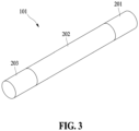
FIG. 3 is a perspective view illustrating the stick-type smoking article 101 including the carbon heat source. - Hereinafter, embodiments will be described in detail with reference to the accompanying drawings. However, various alterations and modifications may be made to the embodiments, and the embodiments are not meant to be limited by the descriptions of the present disclosure. The embodiments should be understood to include all changes, equivalents, and replacements within the idea and the technical scope of the disclosure.
- The terminology used herein is for the purpose of describing particular embodiments only and is not intended to be limiting. The singular forms "a," "an," and "the" are intended to include the plural forms as well, unless the context clearly indicates otherwise. It will be further understood that the terms "comprises/comprising" and/or "includes/including" when used herein, specify the presence of stated features, integers, steps, operations, elements, and/or components, but do not preclude the presence or addition of one or more other features, integers, steps, operations, elements, components and/or groups thereof.
- Unless otherwise defined, all terms including technical and scientific terms used herein have the same meaning as commonly understood by one of ordinary skill in the art to which the embodiments belong. It will be further understood that terms, such as those defined in commonlyused dictionaries, should be interpreted as having a meaning that is consistent with their meaning in the context of the relevant art and will not be interpreted in an idealized or overly formal sense unless expressly so defined herein.
- In addition, when describing the embodiments with reference to the accompanying drawings, like reference numerals refer to like components and a repeated description related thereto will be omitted. In the description of embodiments, detailed description of well-known related structures or functions will be omitted when it is deemed that such description will cause ambiguous interpretation of the present disclosure.
- In addition, the terms first, second, A, B, (a), and (b) may be used to describe components of the embodiments. These terms are used only for the purpose of discriminating one component from another component, and the nature, the sequences, or the orders of the components are not limited by the terms.
- Components included in one embodiment and components having a common function will be described using the same names in other embodiments. Unless otherwise mentioned, the descriptions on the embodiments may be applicable to the following embodiments and thus, duplicated descriptions will be omitted for conciseness.
- Throughout the specification, a "smoking article" refers to an article capable of generating an aerosol, such as tobacco (cigarettes), cigars, and the like. The smoking article may include an aerosol generating material, or an aerosol forming substrate. In addition, the smoking article may include a solid material based on tobacco raw materials such as a reconstituted tobacco sheet, cut tobacco leaves, reconstituted tobacco, and the like. A smoking material may include a volatile compound.
- In addition, throughout the specification, the term "upstream" or "upstream direction" refers to a direction away from a mouth of a user puffing a smoking article, and the term "downstream" or "downstream direction" refers to a direction toward the mouth of the user puffing the smoking article. For example, in a stick-type smoking article shown in
FIG. 3 , atobacco medium portion 202 is disposed upstream or in the upstream direction of afilter portion 203. - Hereinafter, embodiments of the present disclosure will be described in detail with reference to the drawings.
-
FIG. 1 is a diagram illustrating an electricallyheating smoking system 100 including a stick-type smoking article 101 including a carbon heat source, and anautomatic ignition device 102. Referring toFIG. 1 , theautomatic ignition device 102 according to an embodiment of the present disclosure may include astick insertion portion 103, acontroller 104, abattery 105, and anairflow path controller 106. Referring toFIGS. 2 and3 , the stick-type smoking article 101 including the carbon heat source may include acarbon heat source 201, thetobacco medium portion 202, thefilter portion 203, and ametal heat source 204. However, embodiments are not limited thereto, various modifications and additions to the configuration are possible. - According to an embodiment of the present disclosure, the stick-
type smoking article 101 may be provided, and the stick-type smoking article 101 may include thecarbon heat source 201. - In the present disclosure, a temperature of the
carbon heat source 201 does not need to be high enough to cause a combustion or thermal deterioration of thetobacco medium portion 202 during use of the stick-type smoking article 101. However, a combustion temperature of thecarbon heat source 201 needs to be high enough to generate sufficient heat so that sufficient volatile compounds are released from thetobacco medium portion 202. In particular, the combustion temperature needs to be high enough to generate an acceptable aerosol, during an initial smoking puff. To avoid a delay between an ignition of thecarbon heat source 201 and a generation of an aerosol, thecarbon heat source 201 needs to rapidly reach an appropriate combustion temperature after ignition. - The
carbon heat source 201 may have a carbon content of at least 35% by dry weight, more desirably of at least 40% by dry weight, and most desirably of at least about 45% by dry weight of the carbon heat source. - A carbon heat source may be formed of at least one suitable carbon-containing material, and an additive may be included to improve a characteristic of the
carbon heat source 201. In an example, an additive to promote an ignition of a carbon heat source may correspond to perchlorate, chlorate, nitrate, peroxide, permanganate, zirconium, or a combination thereof, and an additive to promote a combustion of a carbon heat source may include, for example, potassium or potassium salts, such as potassium citrate. The types of additives listed above are merely examples and are not limited to the types listed above. - In addition, the
carbon heat source 201 may include at least one ignition aid. - In an embodiment of the present disclosure, the
carbon heat source 201 may include themetal heat source 204. Themetal heat source 204 may include a metal with a low resistance. In an example, a resistance value may have a value greater than 0 Ω and less than 0.7 Ω. Different resistance values of themetal heat source 204 may be set based on, for example, a component, a length, a width, a thickness, and the like of a metal heat source, and a metal having a low resistance may include, for example, gold, silver, copper, aluminum, iron, and the like, but is not limited thereto. - Meanwhile, in the present disclosure, the
metal heat source 204 may include a positive (+) terminal in a central portion, and a negative (-) terminal (round; GND) disposed outside the positive (+) terminal. - Meanwhile, the stick-
type smoking article 101 according to an embodiment of the present disclosure may include thetobacco medium portion 202, thefilter portion 203, and a wrapper. - The
tobacco medium portion 202 typically refers to a tobacco material containing nicotine, such as leaf tobacco, and may further include an excipient. The excipient, which is a material that may be included in thetobacco medium portion 202, may include a pH adjuster, a binder, an aerosol former, other additives, and the like, in addition to tobacco materials, however, embodiments are not limited thereto. - Tobacco materials may be tobacco leaf scraps, tobacco stems, tobacco dust generated during tobacco processing, and/or tobacco leaf prime lamina strip. In addition, the type of tobacco leaves may be at least one selected from flue-cured tobacco, Burley tobacco, and domestic tobacco, such as fire-cured tobacco, sun-cured tobacco, and air-cured tobacco, but is not limited thereto.
- When a pH adjuster is used, any material known in the art may be used as a pH adjuster without significant limitation and may include, for example, a basic inorganic salt.
- In addition, the binder may be a material capable of increasing a hardness by allowing ground tobacco materials to properly bind, and any material known in the art may be used as a binder without limitation and may include, for example, at least one selected from a group consisting of alginate; cellulose, such as methyl cellulose, ethyl cellulose, ethyl hydroxyethyl cellulose, and carboxymethyl cellulose; dextran; gum; gum derivatives, such as hydroxyethyl guar gum, hydroxypropyl guar gum, hydroxyethyl locust bean gum, and hydroxypropyl locust bean gum; pectins, such as fruit pectins, citrus pectins and tobacco pectins; starches, such as modified or derivatized starches; pullulan; and konjac flour.
- In addition, as an example, the aerosol former may be a material that may be volatilized to convey nicotine, and the like, in an aerosol when heated above a specific volatilization temperature, and specific types thereof may be at least one selected from a group consisting of monohydric alcohols, such as menthol; polyhydric alcohols, such as triethylene glycol, tetraethylene glycol, 1,3-butanediol, erythritol, propylene glycol, and glycerol; esters of polyhydric alcohols, such as glycerol mono-, di- or triacetate; aliphatic esters of mono-, di- or polycarboxylic acids, such as diethyl suberate, dimethyl dodecanedioate, dimethyl tetradecanedioate, ethyl laurate, lauryl acetate, and triethyl citrate; benzyl benzoate; benzyl phenyl acetate; ethyl vanillate; lauric acid; myristic acid; propylene carbonate; and tributyrin, but are not limited thereto.
- Moreover, the other additives may further include, but are not limited to, at least one selected from a group consisting of a flavoring agent, a wetting agent, a plasticizer, tobacco and nontobacco fibers, aqueous and non-aqueous solvents, and a combination thereof.
- In addition, the flavoring agent may be an agent that imparts taste and/or flavor to an aerosol generated from a tobacco material. The flavoring agent may include licorice, sucrose, fructose syrup, isosweet, cocoa, lavender, cinnamon, cardamom, celery, fenugreek, cascarilla, sandalwood, bergamot, geranium, honey essence, rose oil, vanilla, lemon oil, orange oil, mint oil, caraway, cognac, jasmine, cacocail, menthol, cassia, ylang-ylang, sage, spearmint, ginger, coriander, coffee, etc., but is not limited thereto. Thus, it is possible to compensate for the lack of smoking flavor and taste of a leaf cigarette, mask undesirable scent and taste, and impart distinguishing flavor.
- The
filter portion 203 may correspond to a cellulose acetate filter, a paper filter, or a filter formed of a polymer material, but is not limited thereto. - In addition, the
filter portion 203 may also be flavored with the flavoring agent. - The wrapper may be manufactured with general filter wrapping paper, and one or more perforations may be selectively formed in a circumferential direction to allow external air to flow in or internal gas to flow out in a tipping wrapper that binds the
tobacco medium portion 202 and a filter, and accordingly, it is possible to realize an air dilution rate of a cigarette and adjust an amount of mainstream smoke components to be transferred. - According to an embodiment of the present disclosure, the electrically
heated smoking system 100 that includes the stick-type smoking article 101 including thecarbon heat source 201, and theautomatic ignition device 102 may be provided. Thecarbon heat source 201 may include themetal heat source 204. Theautomatic ignition device 102 may include thestick insertion portion 103 into which the stick-type smoking article 101 is inserted to ignite thecarbon heat source 201. - In an example, the
automatic ignition device 102 may include theairflow path controller 106. - The
airflow path controller 106 may control an amount of airflow flowing in an airflow path based on a draw resistance during smoking. Specifically, a draw resistance (pressure drop) within the stick-type smoking article 101 may be reduced due to repeated puffing by a user. Theairflow path controller 106 may sense a reduction in the draw resistance and increase the draw resistance of theautomatic ignition device 102 itself. In other words, the present disclosure may provide a uniform draw resistance and taste of tobacco using the airflow path controller only. - In an example, the electrically
heated smoking system 100 may include a sensor configured to sense the draw resistance in the stick-type smoking article 101. A draw resistance detection sensor may sense the draw resistance of the stick-type smoking article 101 after puffing of the user and generate a pressure drop signal. A sensing signal of the draw resistance detection sensor may be transferred to theairflow path controller 106. Theairflow path controller 106 may control an airflow to increase a pressure drop of theautomatic ignition device 102 itself. However, embodiments are not limited thereto. - In the electrically
heated smoking system 100 according to an embodiment of the present disclosure, thestick insertion portion 103 may include a terminal of the automatic ignition device. The terminal of the automatic ignition device may include a positive (+) terminal in a central portion, and a negative (-) terminal disposed outside the positive (+) terminal. Themetal heat source 204 of the stick-type smoking article 101 may include the positive (+) terminal in the central portion, and the negative (-) terminal disposed outside the positive (+) terminal. When the stick-type smoking article 101 is accommodated in thestick insertion portion 103, the positive (+) terminal and the negative (-) terminal of the stick-type smoking article 101 may contact a positive (+) terminal and a negative (-) terminal of theautomatic ignition device 102, respectively, and a current may flow in themetal heat source 204. In other words, thecarbon heat source 201 may be heated by power supplied from thebattery 105. The heatedcarbon heat source 201 may allow an aerosol to be generated from thetobacco medium portion 202. - The
automatic ignition device 102 may be manufactured with various structures having an airflow path, through which external air flows in or internal gas flows out, even in a state in which the stick-type smoking article 101 is accommodated, and embodiments are not limited to the drawings. - In an example, the
automatic ignition device 102 may include thecontroller 104. Thecontroller 104 may control the overall operation of the electricallyheated smoking system 100. - First, power supplied to the
stick insertion portion 103 may be controlled. Specifically, a state in which a terminal of the stick-type smoking article and a terminal of the automatic ignition device contact may be recognized, and power may be controlled to be supplied. Themetal heat source 204 in the stick-type smoking article 101 may heat thecarbon heat source 201. Meanwhile, when preheating is completed by raising a temperature of thecarbon heat source 201 and when thecarbon heat source 201 is ignited, thecontroller 104 may block a current flowing in themetal heat source 204. Accordingly, power consumption may be reduced, and a size of a battery may be reduced, which may be advantageous in device miniaturization and may lead to a simplification of a structure of an electric circuit. When a current reaches a first value, thecontroller 104 may control theairflow path controller 106 to operate. - The
controller 104 may control operations of other components included in theautomatic ignition device 102 in addition to thestick insertion portion 103 and theairflow path controller 106. Thecontroller 104 may identify a state of each of the components of theautomatic ignition device 102 and determine whether a device is operable. However, embodiments are not limited thereto. - The
battery 105 of the present disclosure may supply power required to operate the electricallyheated smoking system 100. For example, thebattery 105 may supply power to heat thestick insertion portion 103 and supply power required to operate thecontroller 104. In addition, thebattery 105 may supply power required to operate a display, a sensor, a motor, and the like, installed in the electricallyheated smoking system 100. However, embodiments are not limited thereto. - According to another embodiment of the present disclosure, an airflow path control method of the electrically
heated smoking system 100 may be provided. Specifically, the airflow path control method may include step C1 of applying a current to themetal heat source 204 when a terminal of the stick-type smoking article and a terminal of the automatic ignition device contact; step C2 of controlling the current flowing in themetal heat source 204 based on a temperature of thecarbon heat source 201; and step C3 of blocking the current and operating theairflow path controller 106. - In step C2, when the
carbon heat source 201 is ignited, the current flowing in themetal heat source 204 may be blocked. - In step C3, the
airflow path controller 106 may control an amount of airflow flowing in an airflow path based on a draw resistance in the stick-type smoking article 101. - However, embodiments are not limited thereto, and general-purpose components other than the components shown in
FIG. 1 may be included in theautomatic ignition device 102. For example, theautomatic ignition device 102 may include a display capable of displaying visual information, and/or a motor to output tactile information, and may further include at least one sensor, for example, a pressure drop detection sensor, a stick-type smoking article insertion recognition sensor, and the like. In addition, although not shown inFIGS. 1 to 3 , theautomatic ignition device 102 may also form a system together with a separate cradle. For example, the cradle may be used to charge thebattery 105 of theautomatic ignition device 102. - While the embodiments are described with reference to drawings, it will be apparent to one of ordinary skill in the art that various alterations and modifications in form and details may be made in these embodiments without departing from the spirit and scope of the claims and their equivalents. For example, suitable results may be achieved if the described techniques are performed in a different order and/or if components in a described system, architecture, device, or circuit are combined in a different manner and/or replaced or supplemented by other components or their equivalents.
- Therefore, other implementations, other embodiments, and equivalents to the claims are also within the scope of the following claims.
Claims (12)
- A stick-type smoking article comprising a carbon heat source, the stick-type smoking article, wherein the carbon heat source comprises a metal heat source.
- The stick-type smoking article of claim 1, wherein the metal heat source comprises a positive (+) terminal in a central portion, and a negative (-) terminal disposed outside the positive (+) terminal.
- The stick-type smoking article of claim 1, wherein the metal heat source is a metal having a resistance greater than 0 Ω and less than 0.7 Ω.
- The stick-type smoking article of claim 1, wherein the metal heat source comprises at least one selected from a group consisting of gold, silver, copper, aluminum, and iron.
- An electrically heated smoking system comprising a stick-type smoking article and an automatic ignition device, whereinthe stick-type smoking article comprises a carbon heat source,the carbon heat source comprises a metal heat source, andthe automatic ignition device comprises a stick insertion portion into which the stick-type smoking article is inserted to ignite a carbon heat source.
- The electrically heated smoking system of claim 5, wherein the automatic ignition device comprises an airflow path controller configured to adjust an amount of airflow path flowing in an airflow path based on a draw resistance.
- The electrically heated smoking system of claim 5, wherein the metal heat source of the stick-type smoking article comprises a positive (+) terminal in a central portion, and a negative (-) terminal disposed outside the positive (+) terminal, and the stick insertion portion comprises a terminal of the automatic ignition device in contact with the positive (+) terminal and the negative (-) terminal.
- The electrically heated smoking system of claim 5, wherein the automatic ignition device comprises a controller, wherein the controller is configured to ignite a carbon heat source by supplying a current only when the stick-type smoking article is preheated, block the current after the igniting, and operate an airflow path controller.
- The electrically heated smoking system of claim 5, wherein the automatic ignition device comprises a battery.
- An airflow control method of the electrically heated smoking system of one of claims 5 to 9, the airflow control method comprising:step C1 of applying a current to a metal heat source when a terminal of the stick-type smoking article and a terminal of the automatic ignition device contact;step C2 of controlling the current flowing in the metal heat source based on a temperature of the carbon heat source; andstep C3 of blocking the current flowing in the metal heat source and operating an airflow path controller.
- The airflow control method of claim 10, wherein, in step C2, the controller is configured to block the current flowing in the metal heat source, when the carbon heat source is ignited.
- The airflow control method of claim 10, wherein, in step C3, the airflow path controller is configured to control an amount of an airflow flowing in an airflow path based on a draw resistance in the stick-type smoking article.
Applications Claiming Priority (2)
| Application Number | Priority Date | Filing Date | Title |
|---|---|---|---|
| KR1020220115085A KR102872475B1 (en) | 2022-09-13 | 2022-09-13 | Stick type smoking article and electrically heated smoking system using the smoking article |
| PCT/KR2023/007501 WO2024058342A1 (en) | 2022-09-13 | 2023-06-01 | Stick-type smoking article and electrically heated smoking system comprising same |
Publications (2)
| Publication Number | Publication Date |
|---|---|
| EP4516132A1 true EP4516132A1 (en) | 2025-03-05 |
| EP4516132A4 EP4516132A4 (en) | 2025-08-06 |
Family
ID=90275397
Family Applications (1)
| Application Number | Title | Priority Date | Filing Date |
|---|---|---|---|
| EP23865647.4A Pending EP4516132A4 (en) | 2022-09-13 | 2023-06-01 | ROD-SHAPED SMOKING ARTICLE AND ELECTRICALLY HEATED SMOKING SYSTEM |
Country Status (6)
| Country | Link |
|---|---|
| US (1) | US20250318573A1 (en) |
| EP (1) | EP4516132A4 (en) |
| JP (1) | JP7846795B2 (en) |
| KR (1) | KR102872475B1 (en) |
| CN (1) | CN119300733A (en) |
| WO (1) | WO2024058342A1 (en) |
Families Citing this family (1)
| Publication number | Priority date | Publication date | Assignee | Title |
|---|---|---|---|---|
| KR20250148986A (en) * | 2024-04-08 | 2025-10-15 | 주식회사 케이티앤지 | Aerosol generating articles and aerosol generating systems |
Family Cites Families (13)
| Publication number | Priority date | Publication date | Assignee | Title |
|---|---|---|---|---|
| US5246018A (en) * | 1991-07-19 | 1993-09-21 | Philip Morris Incorporated | Manufacturing of composite heat sources containing carbon and metal species |
| KR100598131B1 (en) * | 2003-09-01 | 2006-07-11 | 이승현 | Enclosed Smoking Device |
| KR102220688B1 (en) * | 2012-07-04 | 2021-03-03 | 필립모리스 프로덕츠 에스.에이. | Combustible heat source with improved binding agent |
| TR201911322T4 (en) * | 2015-01-28 | 2019-08-21 | Philip Morris Products Sa | Aerosol generating product with integrated heating element. |
| RU2706810C2 (en) | 2015-09-11 | 2019-11-21 | Филип Моррис Продактс С.А. | Multicomponent element for aerosol-generating article |
| GB201602831D0 (en) | 2016-02-18 | 2016-04-06 | British American Tobacco Co | Flavour delivery device |
| WO2018037048A1 (en) * | 2016-08-26 | 2018-03-01 | Philip Morris Products S.A. | Aerosol-generating article comprising an aerosol-forming substrate and a heat-conducting element |
| US11019850B2 (en) * | 2018-02-26 | 2021-06-01 | Rai Strategic Holdings, Inc. | Heat conducting substrate for electrically heated aerosol delivery device |
| KR20210019418A (en) * | 2018-04-27 | 2021-02-22 | 제이티 인터내셔널 소시에떼 아노님 | Smoking articles, smoking systems and methods for generating aerosols |
| US12022859B2 (en) | 2019-07-18 | 2024-07-02 | R.J. Reynolds Tobacco Company | Thermal energy absorbers for tobacco heating products |
| KR102555646B1 (en) * | 2019-12-17 | 2023-07-14 | 필립모리스 프로덕츠 에스.에이. | Combustible heat sources including ignition aids and binders |
| KR102587924B1 (en) * | 2020-08-06 | 2023-10-11 | 주식회사 케이티앤지 | Aerosol generating device |
| CN114532611A (en) * | 2022-03-25 | 2022-05-27 | 深圳麦时科技有限公司 | Carbon cup heating body and aerosol generating product comprising same |
-
2022
- 2022-09-13 KR KR1020220115085A patent/KR102872475B1/en active Active
-
2023
- 2023-06-01 JP JP2024569054A patent/JP7846795B2/en active Active
- 2023-06-01 EP EP23865647.4A patent/EP4516132A4/en active Pending
- 2023-06-01 WO PCT/KR2023/007501 patent/WO2024058342A1/en not_active Ceased
- 2023-06-01 US US18/868,838 patent/US20250318573A1/en active Pending
- 2023-06-01 CN CN202380043331.0A patent/CN119300733A/en active Pending
Also Published As
| Publication number | Publication date |
|---|---|
| EP4516132A4 (en) | 2025-08-06 |
| CN119300733A (en) | 2025-01-10 |
| JP7846795B2 (en) | 2026-04-15 |
| WO2024058342A1 (en) | 2024-03-21 |
| KR102872475B1 (en) | 2025-10-20 |
| JP2025517793A (en) | 2025-06-10 |
| KR20240036353A (en) | 2024-03-20 |
| US20250318573A1 (en) | 2025-10-16 |
Similar Documents
| Publication | Publication Date | Title |
|---|---|---|
| JP2023545973A (en) | Aerosol-generating articles with low density substrates | |
| KR102723138B1 (en) | Aerosol generating device having a sealing element within the cavity | |
| KR102870145B1 (en) | Cartridges for use with aerosol generating devices | |
| JP2018508211A (en) | Feedback controlled RTD adjustment for aerosol generators | |
| CN109996455A (en) | Smoking product | |
| JP7586448B2 (en) | Aerosol generating device with smokeless function and aerosol generating article used therewith | |
| CN117222329A (en) | Piece of tobacco material including flavor material and method of making the piece of tobacco material | |
| US12501935B2 (en) | Aerosol generating apparatus having smokeless function | |
| JP2023545975A (en) | Aerosol generation system with low withdrawal resistance and improved flavor delivery | |
| EP4516132A1 (en) | Stick-type smoking article and electrically heated smoking system comprising same | |
| US20240298693A1 (en) | Tobacco medium and aerosol-generating article comprising the same | |
| EP4201234A1 (en) | Aerosol generating device including a plurality of cartridges | |
| US20240237710A1 (en) | Aerosol-generating article and aerosol-generating device | |
| US20240268451A1 (en) | Aerosol-generating device and medium receiving rod | |
| KR102625764B1 (en) | Aerosol generating article and system | |
| EP4324344A1 (en) | Smoking article, and aerosol-generating system comprising same | |
| US20240245102A1 (en) | Aerosol-generating device and medium receiving rod | |
| KR102716790B1 (en) | Aerosol generating article comprising granules | |
| KR102767323B1 (en) | Aerosol generating article comprising granules | |
| US20240381927A1 (en) | Aerosol generating article and system | |
| EP4197363A1 (en) | Cartridge containing menthol and flavoring agent, and aerosol generating system comprising same | |
| JP7521722B2 (en) | Tobacco rod, aerosol generating article including the same, and aerosol generating device used therewith | |
| US20250318572A1 (en) | Flavored non-heating-type aerosol generating article for preventing reduction of amount of nicotine transfer and aerosol generating system including the same | |
| EP4585062A1 (en) | Smoking article including lyocell tow | |
| KR20230063373A (en) | Granule with multiple susceptors for uniform heating and Aerosol generating article comprising thereof |
Legal Events
| Date | Code | Title | Description |
|---|---|---|---|
| STAA | Information on the status of an ep patent application or granted ep patent |
Free format text: STATUS: THE INTERNATIONAL PUBLICATION HAS BEEN MADE |
|
| PUAI | Public reference made under article 153(3) epc to a published international application that has entered the european phase |
Free format text: ORIGINAL CODE: 0009012 |
|
| STAA | Information on the status of an ep patent application or granted ep patent |
Free format text: STATUS: REQUEST FOR EXAMINATION WAS MADE |
|
| 17P | Request for examination filed |
Effective date: 20241128 |
|
| AK | Designated contracting states |
Kind code of ref document: A1 Designated state(s): AL AT BE BG CH CY CZ DE DK EE ES FI FR GB GR HR HU IE IS IT LI LT LU LV MC ME MK MT NL NO PL PT RO RS SE SI SK SM TR |
|
| A4 | Supplementary search report drawn up and despatched |
Effective date: 20250708 |
|
| RIC1 | Information provided on ipc code assigned before grant |
Ipc: A24D 1/22 20200101AFI20250702BHEP Ipc: A24B 15/16 20200101ALI20250702BHEP |
|
| DAV | Request for validation of the european patent (deleted) | ||
| DAX | Request for extension of the european patent (deleted) |