EP4513786A1 - Kommunikationsverfahren, knoten und benutzergerät - Google Patents
Kommunikationsverfahren, knoten und benutzergerät Download PDFInfo
- Publication number
- EP4513786A1 EP4513786A1 EP23825178.9A EP23825178A EP4513786A1 EP 4513786 A1 EP4513786 A1 EP 4513786A1 EP 23825178 A EP23825178 A EP 23825178A EP 4513786 A1 EP4513786 A1 EP 4513786A1
- Authority
- EP
- European Patent Office
- Prior art keywords
- node
- user equipment
- configuration
- cell
- coordinated operation
- Prior art date
- Legal status (The legal status is an assumption and is not a legal conclusion. Google has not performed a legal analysis and makes no representation as to the accuracy of the status listed.)
- Granted
Links
Images


Classifications
-
- H—ELECTRICITY
- H04—ELECTRIC COMMUNICATION TECHNIQUE
- H04W—WIRELESS COMMUNICATION NETWORKS
- H04W36/00—Hand-off or reselection arrangements
- H04W36/08—Reselecting an access point
-
- H—ELECTRICITY
- H04—ELECTRIC COMMUNICATION TECHNIQUE
- H04W—WIRELESS COMMUNICATION NETWORKS
- H04W36/00—Hand-off or reselection arrangements
- H04W36/0005—Control or signalling for completing the hand-off
- H04W36/0055—Transmission or use of information for re-establishing the radio link
- H04W36/0069—Transmission or use of information for re-establishing the radio link in case of dual connectivity, e.g. decoupled uplink/downlink
-
- H—ELECTRICITY
- H04—ELECTRIC COMMUNICATION TECHNIQUE
- H04W—WIRELESS COMMUNICATION NETWORKS
- H04W36/00—Hand-off or reselection arrangements
- H04W36/34—Reselection control
-
- H—ELECTRICITY
- H04—ELECTRIC COMMUNICATION TECHNIQUE
- H04W—WIRELESS COMMUNICATION NETWORKS
- H04W36/00—Hand-off or reselection arrangements
- H04W36/0005—Control or signalling for completing the hand-off
- H04W36/0055—Transmission or use of information for re-establishing the radio link
Definitions
- the present disclosure relates to a communication method, a node, and a user equipment used in a mobile communication system.
- DC a user equipment (UE) performs wireless communication with a master cell group (MCG) of a master node (MN) and a secondary cell group (SCG) of a secondary node (SN).
- MCG master cell group
- SCG secondary cell group
- SN secondary node
- the roles of the nodes communicating with the UE are divided into the MN and the SN. Except for configurations determined independently by the SN, the MN has the initiative (also referred to as "control authority") to configure and control the UE.
- a plurality of component carriers (CCs) corresponding to a plurality of serving cells is aggregated, enabling the UE to simultaneously perform reception or transmission over the plurality of CCs (i.e., a plurality of cells).
- the plurality of CCs may be contiguous or non-contiguous in the frequency domain.
- One serving cell in each of the MCG and SCG is referred to as a primary cell (PCell), and one or more secondary cells (SCells) are configured for the UE together with the PCell to form a set of serving cells.
- the PCell is also referred to as an SpCell.
- the PCell (SpCell) of the SCG is also referred to as a primary secondary cell (PSCell).
- Non-Patent Document 1 describes multi-connectivity in which a UE simultaneously uses a plurality of SNs (i.e., a plurality of SCGs).
- a UE simultaneously uses a plurality of SNs (i.e., a plurality of SCGs).
- the MN since the MN performs configuration and/or control related to a plurality of SNs, the load on the MN may increase.
- Non-Patent Document 1 3GPP Contribution, RWS - 210143 "Multi Radio Multi Connectivity for Rel-18 "
- a communication method for a user equipment to perform wireless communication with a master node and a plurality of secondary nodes in a mobile communication system includes performing, at the master node, processing of transferring, to at least one of the plurality of secondary nodes, a control authority for performing, on a user equipment, configuration and/or control related to a coordinated operation between the plurality of secondary nodes, and performing, at the secondary node to which the control authority is transferred, the configuration and/or control related to the coordinated operation on the user equipment.
- a node for operating as a master node in a mobile communication system in which a user equipment performs wireless communication with the master node and a plurality of secondary nodes includes a controller configured to perform processing of transferring, to at least one of a plurality of secondary nodes, a control authority for performing, on a user equipment, configuration and/or control related to a coordinated operation between the plurality of secondary nodes.
- a node for operating as a secondary node in a mobile communication system in which a user equipment performs wireless communication with a master node and a plurality of secondary nodes includes a controller configured to perform, on the user equipment, configuration and/or control related to a coordinated operation between the plurality of secondary nodes when a control authority for performing, on the user equipment, the configuration and/or control related to the coordinated operation is transferred from the master node to the node.
- a user equipment for performing wireless communication with a master node and a plurality of secondary nodes includes a wireless communicator configured to receive a signal for configuration and/or control related to a coordinated operation between the plurality of secondary nodes from a secondary node to which a control authority for performing, on the user equipment, the configuration and/or control related to the coordinated operation is transferred from the master node.
- a first embodiment will be described with reference to FIG. 1 to FIG. 11 .
- FIG. 1 is a diagram illustrating a configuration example of a mobile communication system according to the first embodiment.
- the mobile communication system according to the first embodiment is a system conforming to the 3GPP standard.
- the mobile communication system according to the first embodiment may be a 5th Generation (5G) System or a 6th Generation (6G) System.
- the mobile communication system includes a network (NW) 1 and a user equipment (UE) 100.
- the UE 100 is a mobile communication apparatus and performs wireless communication with the NW 1.
- the UE 100 may be an apparatus used by a user and may be, for example, a mobile phone terminal (including a smartphone), a tablet terminal, a laptop personal computer (PC), a communication module (including a communication card or chipset), a sensor or an apparatus provided in a sensor, a vehicle or an apparatus provided in a vehicle (Vehicle UE), an aircraft or an apparatus provided in an aircraft (Aerial UE).
- the NW 1 includes a radio access network (RAN) 10 and a core network (CN) 20.
- RAN radio access network
- CN core network
- the RAN 10 is called a Next Generation Radio Access Network (NG-RAN)
- NG-RAN Next Generation Radio Access Network
- GC 5G Core Network
- the RAN 10 includes a plurality of nodes 200 (nodes 200a to 200c in the illustrated example).
- the nodes 200 are connected to each other via inter-node interfaces.
- the nodes 200 are also called base stations.
- Each node 200 may include (i.e., be functionally divided into) a Central Unit (CU) and a Distributed Unit (DU), and the two units may be connected through a fronthaul interface.
- CU Central Unit
- DU Distributed Unit
- the two units may be connected through a fronthaul interface.
- the nodes 200 are called gNBs
- the inter-node interfaces are called Xn interfaces
- the fronthaul interface is called an F1 interface.
- Each node 200 manages one or more cells.
- the node 200 performs wireless communication with the UE 100 that has established connections to the cells of the node 200.
- Each node 200 has a radio resource management (RRM) function, a user data (also simply referred to as “data”) routing function, a measurement control function for mobility control/scheduling, and the like.
- RRM radio resource management
- a "cell” is used as a term indicating a minimum unit of a wireless communication area.
- the "cell” is also used as a term representing a function or a resource for performing wireless communication with the UE 100.
- One cell belongs to one carrier frequency (also simply referred to as one "frequency").
- the CN 20 includes a CN apparatus 300.
- the CN apparatus 300 may include a control plane (C-plane) apparatus corresponding to a C-plane and a user plane (U-plane) apparatus corresponding to a U-plane.
- the C-plane apparatus performs various mobility control, paging, and the like for the UE 100.
- the C-plane apparatus communicates with the UE 100 using Non-Access Stratum (NAS) signaling.
- NAS Non-Access Stratum
- the U-plane apparatus performs data transfer control.
- the C-plane apparatus is called an Access and Mobility Management Function (AMF)
- the U-plane apparatus is called a User Plane Function (UPF)
- the interfaces between the node 200 and the CN apparatus 300 are called NG interfaces.
- AMF Access and Mobility Management Function
- UPF User Plane Function
- FIG. 2 is a diagram illustrating a configuration example of a radio interface protocol stack of the U-plane that handles data.
- the U-plane radio interface protocols include, for example, a physical (PHY) layer, a Medium Access Control (MAC) layer, a Radio Link Control (RLC) layer, a Packet Data Convergence Protocol (PDCP) layer, and a Service Data Adaptation Protocol (SDAP) layer.
- PHY physical
- MAC Medium Access Control
- RLC Radio Link Control
- PDCP Packet Data Convergence Protocol
- SDAP Service Data Adaptation Protocol
- the PHY layer performs coding and decoding, modulation and demodulation, antenna mapping and demapping, and resource mapping and demapping. Data and control information is transferred between the PHY layer of the UE 100 and the PHY layer of the node 200 via a physical channel.
- the PHY layer of the UE 100 receives downlink control information (DCI) transmitted from the node 200 over a physical downlink control channel (PDCCH).
- DCI downlink control information
- PDCCH physical downlink control channel
- RNTI radio network temporary identifier
- the DCI transmitted from the node 200 is appended with CRC parity bits scrambled by the RNTI.
- the MAC layer performs data priority control, retransmission processing through hybrid ARQ (HARQ), and the like. Data and control information is transferred between the MAC layer of the UE 100 and the MAC layer of the node 200 via a transport channel.
- the MAC layer of the node 200 includes a scheduler. The scheduler determines uplink and downlink transport formats (transport block sizes and modulation and coding schemes (MCSs)) and resources allocated to the UE 100.
- MCSs modulation and coding schemes
- the RLC layer transfers data to the RLC layer on the reception side by using functions of the MAC layer and the PHY layer. Data and control information is transferred between the RLC layer of the UE 100 and the RLC layer of the node 200 via a logical channel.
- the PDCP layer performs header compression/decompression, encryption/decryption, and the like.
- the SDAP layer performs mapping between an IP flow which is the unit in which the CN 20 performs QoS control and a radio bearer which is the unit in which an Access Stratum (AS) performs QoS control. Note that, when the RAN is connected to the EPC, the SDAP need not be provided.
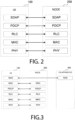
- FIG. 3 is a diagram illustrating a configuration example of a radio interface protocol stack of the C-plane that handles signaling (control signals).
- the radio interface protocol stack of the C-plane includes, for example, a Radio Resource Control (RRC) layer and a Non-Access Stratum (NAS) layer instead of the SDAP layer illustrated in FIG. 2 .
- RRC Radio Resource Control
- NAS Non-Access Stratum
- RRC signaling for various configurations is transferred between the RRC layer of the UE 100 and the RRC layer of the node 200.
- the RRC layer controls a logical channel, a transport channel, and a physical channel according to establishment, re-establishment, and release of a radio bearer.
- RRC connection When there is a connection between the RRC of the UE 100 and the RRC of the node 200 (RRC connection), the UE 100 is in an RRC connected state.
- RRC connection When there is no connection between the RRC of the UE 100 and the RRC of the node 200 (RRC connection), the UE 100 is in an RRC idle state.
- the connection between the RRC of the UE 100 and the RRC of the node 200 is suspended, the UE 100 is in an RRC inactive state.
- the NAS layer (also simply referred to as a "NAS") located above the RRC layer performs session management, mobility management, and the like. NAS signaling is transferred between the NAS layer of the UE 100 and the NAS layer of the CN apparatus 300.
- the UE 100 includes an application layer other than the protocol of the radio interface.
- Each layer lower than the NAS layer is referred to as an AS layer (also simply referred to as an "AS").
- FIG. 4 is a diagram for illustrating terahertz (THz) wave cells according to the first embodiment.
- the mobile communication system according to the first embodiment may be a 6G system.
- 6G is expected to utilize terahertz (THz) waves.
- THz wave cell A cell that operates with THz waves is called a THz wave cell.
- mmW millimeter waves
- THz waves have higher propagation, higher free space loss, and are more susceptible to the effects of the atmosphere and rainfall.
- THz wave cells can be ultra-compact size cells.
- the diameter of the coverage area of a THz wave cell is about 10 m
- the diameter of the coverage area of a mmW cell that operates with mmW is about 100 m
- the diameter of the coverage area of a macro cell is about 1000 m.
- the UE 100 which is moving at, for example, 60 km/s passes through the coverage area of each THz wave cell in about 599 ms.
- Dual Connectivity is one method for reliably controlling compact size cells in a mobile communication system.
- FIG. 5 is a diagram for illustrating dual connectivity (DC) according to the first embodiment.
- the first embodiment assumes that a THz wave cell is used as a cell of a secondary cell group (SCG).
- the THz wave cell may be used as a secondary cell (SCell) of a master cell group (MCG).
- MCG master cell group
- an mmW cell may be used instead of the THz wave cell.
- DC can be configured for the UE 100 in an RRC connected state.
- the UE 100 performs wireless communication with the master cell group (MCG) managed by a master node (MN) 200M and the secondary cell group (SCG) managed by a secondary node (SN).
- MCG master cell group
- SCG secondary cell group
- SN secondary node
- the MN 200M and the SN 200S are connected to each other via an inter-node interface.
- the MN 200M and the SN 200S are hereinafter simply referred to as the node 200 when MN 200M and the SN 200S are not distinguished from each other.
- the MN 200M is also referred to as master gNB (MgNB) when the MN 200M is a node of 5G/NR.
- MgNB master gNB
- the SN 200M is also referred to as secondary gNB (sgNB) when the SN 200M is a node of 5G/NR.
- the MN 200M has the initiative (control authority) to perform configuration and control on the UE 100 except for configurations that are independently determined by the SN 200S.
- the MN 200M transmits a predetermined message (for example, an SN Addition Request message) to the SN 200S and the MN 200M transmits an RRC Reconfiguration message to the UE 100
- a predetermined message for example, an SN Addition Request message
- the MN 200M transmits an RRC Reconfiguration message to the UE 100
- the UE 100 in the RRC connected state is allocated radio resources from schedulers of the MN 200M and the SN 200S, and performs wireless communication using the radio resources of the MN 200M and the radio resources of the SN 200S.
- the MN 200M may have a control plane connection with the CN20.
- the MN 200M provides main radio resources for the UE 100.
- the MN 200M manages the MCG that is a group of serving cells associated with the MN 200M.
- the MCG includes a primary cell (PCell) and optionally one or more secondary cells (SCells).
- the SN 200S need not have control plane connection with the CN20.
- the SN 200S provides additional radio resources to the UE 100.
- the SN 200S manages the SCG that is a group of serving cells associated with the SN 200S.
- the SCG includes a primary secondary cell (PSCell) and optionally one or more SCells. Note that the PCell of the MCG and the PSCell of the SCG may be referred to as a special cell (SpCell).
- the UE 100 utilizes only one SN 200S. In other words, the UE 100 cannot use a plurality of SNs 200S at the same time.
- the first embodiment assumes multi-connectivity in which UE 100 simultaneously uses a plurality of SNs 200S (i.e., a plurality of SCGs).
- the mobile communication system supports L1/L2 triggered mobility (LTM).
- LTM L1/L2 triggered mobility
- LTM is a technique for triggering cell switching by signaling of lower layers, layer 1 (L1) and/or layer 2 (L2), thus reducing delay of mobility compared to a general handover procedure.
- the node 200 prepares LTM candidate cell configurations for a candidate cell for a switching destination and provides the LTM candidate cell configuration to the UE 100 via RRC signaling.
- the node 200 receives a layer 1 (L1) measurement report from the UE 100 and transmits a cell switch command indicating LTM candidate cell configurations to the UE 100 via a MAC CE (Control Element), based on the L1 measurement report.
- a trigger for the cell switching is carried in a MAC CE including at least candidate configuration indexes together with a beam indicator.
- the UE 100 changes the serving cell according to the cell switch command.
- cell switching is triggered by the node 200 selecting an LTM candidate cell configuration as the target configuration.
- the LTM candidate cell configurations can be added, modified, and released by the node 200 via RRC signaling.
- the first embodiment assumes a scenario in which the LTM is used to change the PSCell of the UE 100 between the SNs 200S. Such a scenario will be described in detail below.
- FIG. 6 is a diagram illustrating an example of an LTM procedure according to the first embodiment.
- the illustrated example assumes that the UE 100 performs cell switching from the first cell of the node 200 to the second cell of the node 200.
- the first cell and the second cell may include mutually different transmission and reception points (TRPs).
- TRPs transmission and reception points
- step S11 the UE 100 is in the RRC connected state in a cell of the node 200.
- step S12 the UE 100 transmits a Measurement Report message being an RRC message to the node 200.
- step S13 the node 200 determines to use LTM, based on the Measurement Report message and starts preparing candidate cells.
- step S14 the node 200 transmits, to the UE 100, an RRC Reconfiguration message including LTM candidate cell configurations (LTM Candidate Configurations) of one or more candidate cells.
- LTM candidate cell configurations LTM Candidate Configurations
- step S 15 the UE 100 stores LTM candidate cell configurations and transmits an RRC Reconfiguration Complete message to the node 200.
- the UE 100 may perform downlink (DL) synchronization and timing advance (TA) acquisition with the candidate cell before receiving the cell switch command.
- DL downlink
- TA timing advance
- step S17 the UE 100 performs layer 1 (L1) measurement in the configured candidate cell and transmits a lower layer measurement report (L1 Measurement Report) to the node 200.
- L1 Measurement Report may be transmitted and received in the L1, which is the PHY layer.
- the L1 Measurement Report may be transmitted and received in the layer 2 (L2) including the MAC-layer, the RLC-layer, and the PDCP-layer. Note that the order of step S16 and step S17 may be inverted.
- step S18 the node 200 determines to perform cell switching to the target cell (second cell).
- step S19 the node 200 transmits, to the UE 100, a Cell Switch Command (MAC CE) including the candidate configuration index of the target cell.
- MAC CE Cell Switch Command
- step S20 the UE 100 switches to the target cell configuration.
- the UE 100 detaches from the source cell (first cell) and applies the configuration of the target cell.
- step S21 when the cell switching needs to include performing a random access procedure, the UE 100 performs the random access procedure on the target cell.
- the UE 100 may skip the random access procedure.
- step S22 the UE 100 indicates that cell switching to the target cell is successfully completed.
- the UE 100 may then perform steps S16 through S22 multiple times for subsequent LTM cell switching, based on the configuration provided in step S14.
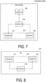
- FIG. 7 is a diagram illustrating a configuration example of the node 200 (base station) according to the first embodiment.
- the node 200 may be the MN 200M or the SN 200S.
- the node 200 includes a transmitter 210, a receiver 220, the controller 230, and a NW communicator 240.
- the transmitter 210 and the receiver 220 constitute a wireless communicator 250 that performs wireless communication with the UE 100.
- the transmitter 210 performs various types of transmission under control of the controller 230.
- the transmitter 210 includes an antenna and a transmission device.
- the transmission device converts a baseband signal (a transmission signal) output by the controller 230 into a radio signal and transmits the resulting signal through the antenna.
- the receiver 220 performs various types of reception under control of the controller 230.
- the receiver 220 includes an antenna and a reception device.
- the reception device converts a radio signal received through the antenna into a baseband signal (a reception signal) and outputs the resulting signal to the controller 230.
- the controller 230 performs various types of control and processes in the node 200. The operations of the node 200 described above and below may also be performed under the control of the controller 230.
- the controller 230 includes at least one processor and at least one memory.
- the memory stores a program to be executed by the processor and information to be used for processing by the processor.
- the processor may include a baseband processor and a CPU.
- the baseband processor performs modulation and demodulation, coding and decoding, and the like of a baseband signal.
- the CPU executes the program stored in the memory to thereby perform various types of processing.
- the NW communicator 240 is connected to adjacent nodes via inter-node interfaces.
- the NW communicator 240 is connected to the CN apparatus 300 via a node-CN interface.
- the node 200 configured as described above may operate as the MN 200M when the UE 100 performs wireless communication with the MN 200M and the plurality of SNs 200S (i.e., multi-connectivity).
- the controller 230 of the node 200 operating as the MN 200M performs control in such a manner that a control authority for performing, on the UE 100, configuration and/or control related to a coordinated operation between the plurality of SNs 200S is transferred to at least one of the plurality of SNs 200S.
- the node 200 may operate as the SN 200S when the UE 100 performs wireless communication with the MN 200M and the plurality of SNs 200S (i.e., multi-connectivity).
- the controller 230 of the node 200 operating as the SN 200S performs, on the UE 100, the configuration and/or control related to the coordinated operation between the plurality of SNs 200S, when the control authority to perform the configuration and/or control for the coordinated operation is transferred from the MN 200M to the node 200.
- FIG. 8 is a diagram illustrating a configuration example of the UE 100 (user equipment) according to the first embodiment.
- the UE 100 includes a receiver 110, a transmitter 120, and a controller 130.
- the receiver 110 and the transmitter 120 constitute a wireless communicator 140 that performs wireless communication with the node 200.
- the receiver 110 performs various types of reception under control of the controller 130.
- the receiver 110 includes an antenna and a reception device.
- the reception device converts a radio signal received through the antenna into a baseband signal (a reception signal) and outputs the resulting signal to the controller 130.
- the transmitter 120 performs various types of transmission under control of the controller 130.
- the transmitter 120 includes an antenna and a transmission device.
- the transmission device converts a baseband signal (a transmission signal) output by the controller 130 into a radio signal and transmits the resulting signal through the antenna.
- the controller 130 performs various types of control and processes in the UE 100. The operations of the UE 100 described above and below may also be performed under the control of a controller 230.
- the controller 130 includes at least one processor and at least one memory.
- the memory stores a program to be executed by the processor and information to be used for processing by the processor.
- the processor may include a baseband processor and a Central Processing Unit (CPU).
- the baseband processor performs modulation and demodulation, coding and decoding, and the like of a baseband signal.
- the CPU executes the program stored in the memory to thereby perform various types of processing.
- the UE 100 configured as described above may perform wireless communication (i.e., multi-connectivity) with the MN 200M and the plurality of SNs 200S.
- the wireless communicator 140 (receiver 110) of the UE 100 receives a radio signal for the configuration and/or control related to the coordinated operation between the plurality of SNs 200S, from the SN 200S to which the control authority for performing the configuration and/or control for the coordinated operation is transferred from the MN 200M.
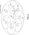
- FIG. 9 is a diagram for illustrating an operation scenario of the mobile communication system according to the first embodiment.
- the UE 100 performs multi-connectivity-based wireless communication with the MN 200M and a plurality of SNs 200S (SN 200S #1 and SN 200S #2).
- Each SN 200S has a narrower cell coverage than the MN 200M.
- each SN 200S (SCG) is operated at a higher frequency than the MN 200M (MCG).
- MCG MN 200M
- MCG MN 200M
- each SN 200S (SCG) may be operated in the THz band or the mmW band.
- the first embodiment mainly assumes a scenario in which each SN 200S (SCG) is operated in the THz band.
- multi-connectivity is preferably achieved by configuring a plurality of SCGs for the UE 100, with switching performed between the SCGs due to movement of the UE 100.
- the MN 200 needs to perform configuration and/or control for a plurality of SNs 200S, and the load on the MN 200M may increase.
- the MN 200M manages all control operations as in DC, the load on the MN 200M increases significantly, and this is not preferable.
- the authority is transferred from the MN 200M to the SN 200S to reduce the load on MN 200M.
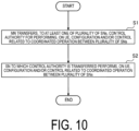
- FIG. 10 is a diagram providing an overview of operations of the mobile communication system according to the first embodiment.
- step S 1 the MN 200M transfers, to at least one SN 200S of the plurality of SNs 200S, the control authority for performing, for the UE 100, the configuration and/or control related to the coordinated operation between the plurality of SNs 200S.
- the MN 200M transmits, to at least one of the plurality of SNs 200S, a first message for requesting the coordinated operation between the plurality of SNs 200S.
- step S2 the SN 200S to which the control authority has been transferred performs, on the UE 100, the configuration and/or control related to the coordinated operation between the plurality of SNs 200S.
- the SN 200S may transmit a second message for starting the coordinated operation between the plurality of SNs 200S, to another SN 200S included in the plurality of SNs 200S.
- the coordinated operation between the plurality of SNs 200S is a cell switching operation for switching the serving cell of the UE 100 between the SN 200S.
- the MN 200M transfers the authority in such a manner that the mobility of the UE 100 is controlled between the SNs 200S.
- the first embodiment assumes a scenario in which the above-described cell switching operation (mobility control) based on the LTM is performed.
- the UE 100 is configured with the cells (TRPs) of the plurality of SNs 200S, and the LTM is used to change the PSCell of the UE 100 between the SNs 200S.
- TRPs cells
- each SN 200S may not know with which SN 200S the coordinated operation (TRP coordinated operation) is to be performed.
- the combination of the SNs 200S to perform the coordinated operation can be identified by the first message and/or the second message described above.
- FIG. 11 is a diagram illustrating an example of operations of the mobile communication system according to the first embodiment.
- dashed lines indicate non-essential steps.
- step S101 the UE 100 performs dual-connectivity (DC) wireless communication with the MN 200M and the SN 200S #1.
- DC dual-connectivity
- the UE 100 may transmit, to the MN 200M, a Measurement Report message including radio quality measurement results for the respective cells.
- the MN 200M may receive the Measurement Report message from the UE 100.
- the MN 200M determines the combination of the SNs 200S to be operated in coordination. For example, based on the Measurement Report message in step S102, the MN 200M identifies a cell having radio quality satisfying a predetermined condition, and determines the SN 200S to which the identified cell belongs.
- the MN 200M is assumed to have determined the SN 200S #2 as the SN 200S to be operated in coordination with the SN 200S #1.
- the MN 200M may determine the SN 200S #2 as SN 202S to be operated in coordination with the SN 200S #1, based on the combination of the SNs 200S (or a combination of cells) configured by the network operator (Operation Administration and Management (OAM)).
- the MN 200M may determine the cell of the SN 200S #1 as a source cell for the LTM and may determine the cell of SN 200S #2 to be a candidate cell (or target cell) for the LTM.
- the MN 200M transmits, to the SN 200S #1, an S-node Pairing Request message that is a request message (first message) for the coordinated operation.
- the MN 200M transmits the S-node Pairing Request message to the SN 200S #1.
- the MN 200M may transmit the S-node Pairing Request message to the SN 200S #2, or may transmit the S-node Pairing Request message to both the SN 200S #1 and the SN 200S #2.
- the S-node Pairing Request message may be a request message for requesting to change the PSCell of the UE 100 between the SNs 200S using the LTM.
- the coordinated operation request message (first message) is a new message transmitted and received on the inter-node interface but that the coordinated operation request message (first message) may be an existing message (for example, S-NODE MODIFICATION REQUEST message) defined in the 3GPP technical specifications.
- the coordinated operation request message (first message) may be a request message (for example, an S-node Xn Establishment Request message) for requesting establishment of an inter-node interface between the SNs 200S.
- the coordinated operation request message includes at least one piece of information among the following 1) to 5).
- the coordinated operation request message includes at least one selected from the group consisting of a UE identifier for identifying the UE 100, a node identifier for identifying the SN 200S which is the partner of the coordinated operation, a cell identifier for identifying the cell of the SN 200S which is the partner of the coordinated operation, a type identifier indicating the type of the coordinated operation, and a UE context of the UE 100.
- step S105 when the SN 200S #1 that has received the request message from the MN 200M includes no inter-node interface with the SN 200S #2 specified in the request message, the SN 200S #1 transmits, to the SN 200S #2, a message (for example, an XN SETUP REQUEST message) requesting establishment of the inter-node interface.
- a message for example, an XN SETUP REQUEST message
- the SN 200S #1 need not transmit, to the SN 200S #2, the message (for example, the XN SETUP REQUEST message) for requesting establishment of the inter-node interface.
- step S106 upon receiving the message from the SN 200S #1 in step S105, the SN 200S #2 transmits, to the SN 200S #1, a response message (for example, an XN SETUP RESPONSE message) to the message.
- a response message for example, an XN SETUP RESPONSE message
- step S107 upon receiving the request message from the MN 200M, the SN 200S #1 transmits a request message (for example, an S-node Coordination Request message) for starting the designated coordinated operation, to the SN 200S #2 designated in the request message.
- the request message includes at least one piece of information among 1) to 5) described above similarly to the message in step S104.
- step S108 upon receiving the request from the SN 200S #1 in step S107, the SN 200S #2 accepts the request and performs various configurations, and then transmits a response message (for example, an S-node Coordination Response message) to the SN 200S #1.
- the response message may include an RRC configuration related to SN 200S #2.
- the RRC configuration includes at least one of the following a) or b).
- the SN 200S #1 transmits, to the MN 200M, a response message (for example, an S-node Pairing Response message) to the request message in step S104.
- the response message may include the RRC configuration of the SN 200S #2 (acquired in step S108 and which may include the configuration of the L1 Measurement Report configuration), and/or the RRC configuration of the SN 200S #1.
- the MN 200M may transmit an RRC Reconfiguration message to the UE 100.
- the SN 200S #1 may transmit the RRC Reconfiguration message to the UE 100.
- the RRC Reconfiguration message may include configuration information related to the SN 200S #1 (for example, the RRC configuration) and/or configuration information related to the SN 200S #2 (for example, the RRC configuration and/or the configuration of the L1 Measurement Report).
- the RRC Reconfiguration message may include an LTM candidate cell configuration (LTM Candidate Configuration) in which the cell of SN 200S #2 is set as a candidate cell.
- the UE 100 may store the configuration information in the RRC Reconfiguration message, and transmit an RRC Reconfiguration Complete message to the MN 200M (or SN 200S #1).
- step S112 the UE 100 is configured with the SN 200S #1 and the SN 200S #2, leading to a multi-connectivity state.
- the SN 200S #1 and the SN 200S #2 control the UE 100 in coordination.
- the UE 100 may transmit the L1 Measurement Report to the SN 200S #1.
- the SN 200S #1 may determine the cell switching to the cell of the SN 200S #2, based on the L1 Measurement Report.
- step S114 the SN 200S #1 transmits, to the UE 100, a Cell Switch Command (MAC CE) including information indicating the cell of the SN 200S #2.
- MAC CE Cell Switch Command
- step S115 in response to the Cell Switch Command (MAC CE), the UE 100 applies the configuration of the cell (target cell) of the SN 200S #2 and is detached from the cell (source cell) of the SN 200S #1.
- MAC CE Cell Switch Command
- step 5116 UE 100 accesses the cell (target cell) of SN 200S #2.
- step S117 when the SN 200S #2 detects the access of the UE 100 (connection completion), the SN 200S #2 may notify the SL #1 of UE access completion.
- the notification may include the UE context for the UE 100.
- the notification may include the latest RRC configuration (the content of RRC Reconfiguration).
- the SN 200S #1 may notify the MN 200M of completion of change of the PSCell (PCell) for the UE 100.
- the notification may include the UE context for the UE 100.
- the notification may include the latest RRC configuration (the content of RRC Reconfiguration).
- the notification may include information such as the node ID of SN 200S #2.
- the MN 200N determines (specifies) a combination of SNs 200S to be operated in coordination.
- the SN 200S may determine the combination of the SNs 200S to be operated in coordination.
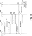
- FIG. 12 is a diagram illustrating variation of operations of the mobile communication system according to the first embodiment.
- dashed lines indicate non-essential steps.
- the SN 200S #1 determines a combination of SNs 200S to be operated in coordination.
- the SN 200S #1 may determine the SN 200S #2 as the SN 200S to be operated in coordination with the SN 200S #1, based on the combination of the SNs 200S (or a combination of cells) configured by the network operator (OAM).
- OAM network operator
- step S121 the SN 200S #1 transmits, to the MN 200M, a message (for example, an S-node Pairing Required message) indicating a request for a coordinated operation with the SN 200S #2.
- the message includes at least one piece of information out of the following 1) to 5).
- step S104 the MN 200M transmits, to the SN 200S #1, an S-node Pairing Request message, which is a request message (first message) for a coordinated operation.
- the message is similar to that in the embodiment described above.
- the MN 200M may transmit, to the SN 200S #1, a response message indicating that the request in step S121 is allowed. Subsequent operations are similar to the corresponding operations in the embodiment described above.
- a second embodiment will be described with reference to FIG. 13 and FIG. 14 , focusing on differences from the first embodiment described above.
- the coordinated operation between a plurality of SNs 200S is the cell switching operation of switching the serving cell of the UE 100 between the SNs 200S.
- the coordinated operation between the plurality of SNs 200S is an operation in which instead of the MN 200M, a certain SN 200S (first secondary node) performs, for the UE 100, configuration and/or control of communication between another SN 200S (second secondary node) and the UE 100.
- the SN 200S functions as a proxy node (also referred to as a "proxy MN") of the MN 200M in order to perform configuration and/or control related to another SN 200S.
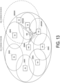
- FIG. 13 is a diagram for illustrating an operation scenario for the mobile communication system according to the second embodiment.
- the UE 100 performs multi-connectivity-based wireless communication with the MN 200M and a plurality of SNs 200S (SN 200S #1 to SN 200S #3).
- the SN 200S #1 has a narrower cell coverage than the MN 200M.
- the SN 200S #1 is operated at a higher frequency than the MN 200M.
- the MN 200M may be operated in the Sub-6 band and the SN 200S #1 may be operated in the mmW band.
- Each of the SN 200S #2 and the SN 200S #3 has narrower cell coverage than the SN 200S #1.
- each of the SN 200S #2 and the SN 200S #3 is operated at a higher frequency than the SN 200S #1.
- the SN 200S #1 may be operated in the mmW band
- each of the SN 200S #2 and the SN 200S #3 may be operated in the THz band.
- the MN 200M causes the SN 200S #1 to perform control related to the SN 200S #2 and the SN 200S #3 (i.e., transfers the control authority to the SN 200S #1).
- the SN 200S #1 to which the control authority is transferred performs, for the UE 100, configuration and/or control of communication between the UE 100 and the SN 200S #2 and SN 200S #3.
- FIG. 14 is a diagram illustrating an example of operations of the mobile communication system according to the second embodiment.
- dashed lines indicate non-essential steps.
- step S201 the UE 100 performs dual-connectivity (DC) wireless communication with the MN 200M and the SN 200S #1.
- DC dual-connectivity
- the UE 100 may transmit, to the MN 200M, the Measurement Report message including radio quality measurement results for the respective cells.
- the MN 200M may receive the Measurement Report message from the UE 100.
- the MN 200M determines a combination of the SNs 200S to be operated in coordination. For example, based on the Measurement Report message in step S202, the MN 200M identifies a cell having radio quality satisfying a predetermined condition, and determines the SN 200S to which the identified cell belongs.
- the MN 200M is assumed to have determined the SN 200S #2 as the SN 200S to be operated in coordination with the SN 200S #1.
- the MN 200M may determine the SN 200S #2 as the SN 200S to be operated in coordination with the SN 200S #1, based on the combination of the SN 200S (or a combination of cells) configured by the network operator (OAM).
- the MN 200M may determine the SN 200S #1 as the SN 200S (proxy MN) to perform control related to the SN 200S #2.
- step S204 the MN 200M transmits, to the SN 200S #1, the S-node Pairing Request message that is a request message (first message) for the coordinated operation.
- the MN 200M transmits the S-node Pairing Request message to the SN 200S #1.
- the MN 200M may transmit the S-node Pairing Request message to the SN 200S #2, or may transmit the S-node Pairing Request message to both the SN 200S #1 and the SN 200S #2.
- the S-node Pairing Request message may be an operation request to perform SN control as a proxy MN, to be specific, a message indicating that the SN 200S #1 is specified as a SN 200S (proxy MN) for performing control related to the SN 200S #2.
- the coordinated operation request message (first message) is a new message transmitted and received on the inter-node interface but that the coordinated operation request message (first message) may be an existing message (for example, S-NODE MODIFICATION REQUEST message) defined in the 3GPP technical specifications.
- the coordinated operation request message (first message) may be a request message (for example, an S-node Xn Establishment Request message) for requesting establishment of an inter-node interface between the SNs 200S.
- the request message (first message) for the coordinated operation includes at least one piece of information among 1) to 5) described above.
- the information indicating the type of the target coordinated operation may be information indicating the "proxy MN".
- step S205 when the SN 200S #1 that has received the request message from the MN 200M includes no inter-node interface with the SN 200S #2 specified in the request message, the SN 200S #1 transmits, to the SN 200S #2, the message (for example, the XN SETUP REQUEST message) requesting establishment of the inter-node interface.
- the message for example, the XN SETUP REQUEST message
- the SN 200S #1 need not transmit, to the SN 200S #2, the message (for example, the XN SETUP REQUEST message) for requesting establishment of the inter-node interface.
- step S206 upon receiving the message from the SN 200S #1 in step S205, the SN 200S #2 transmits, to the SN 200S #1, the response message (for example, the XN SETUP RESPONSE message) to the message.
- the response message for example, the XN SETUP RESPONSE message
- step S207 upon receiving the request message from the MN 200M, the SN 200S #1 transmits the request message (for example, the S-node Coordination Request message) for starting the designated coordinated operation, to the SN 200S #2 designated in the request message.
- the request message includes at least one piece of information among 1) to 5) described above similarly to the message in step S204.
- step S208 upon receiving the request from the SN 200S #1 in step S207, the SN 200S #2 accepts the request and performs various configurations, and then transmits the response message (for example, the S-node Coordination Response message) to the SN 200S #1.
- the response message may include the RRC configuration related to SN 200S #2.
- the RRC configuration may include configuration information related to the cell (candidate cell) managed by SN 200S #2.
- the configuration information may include the configuration information of the cell, for example, the cell ID and the physical layer configuration.
- the SN 200S #1 transmits, to the MN 200M, the response message (for example, the S-node Pairing Response message) to the request message in step S204.
- the response message may include the RRC configuration of the SN 200S #2 (obtained in step S208) and/or the RRC configuration of the SN 200S #1.
- the UE 100 may store the configuration information in the RRC Reconfiguration message, and transmit the RRC Reconfiguration Complete message to the MN 200M (or SN 200S #1).
- step S212 the UE 100 is configured with the SN 200S #1 and the SN 200S #2, leading to a multi-connectivity state.
- the SN 200S #1 and the SN 200S #2 control the UE 100 in coordination.
- the SN 200S #1 achieves dual connectivity (DC) with the SN 200S #2.
- the DC between the SN 200S #1 and the SN 200S #2 may be configured in such a manner as to take over the DC between the MN 200M and the SN 200S #1.
- the DC configuration between SN 200S #1 and SN 200S #2 may be performed as a new configuration.
- step S217 when the UE context and/or the RRC configuration held by the SN 200S #1 is updated, the SN 200S #1 may transmit the UE context and/or the RRC configuration to the MN 200M.
- the MN 200M side modifies the configuration of the UE 100 to modify the UE context and/or the RRC configuration held by the MN 200M
- the MN 200M may transmit the UE context and/or the RRC configuration to the SN 200S #1.
- synchronization processing is executed in such a manner that the MN 200M and the SN 200S #1 (proxy MN) hold the same UE context and/or RRC configuration.
- the SN 200S #1 operating as the proxy MN, may transmit, to the SN 200S to be controlled (for example, the SN 200S #2), the request message for requesting to change the PSCell between the SNs 200S using the LTM according to the first embodiment.
- a program that causes the computer (the UE 100, the node 200) to perform operations according to the embodiments described above may be provided.
- the program may be recorded on a computer readable medium.
- the computer readable medium allows installation of the program on a computer.
- the computer readable medium on which the program is recorded may be a non-transitory recording medium.
- the non-transitory recording medium is not particularly limited, and may be, for example, a recording medium such as a CD-ROM or a DVD-ROM.
- first and second elements may be used herein as a convenient method of distinguishing between two or more elements.
- a reference to first and second elements does not mean that only two elements may be employed there or that the first element precedes the second element in some manner.
- articles are added by translation, for example, "a”, “an”, and “the” in English, these articles are intended to include the plural unless the context clearly indicates otherwise.
- a communication method for a user equipment to perform wireless communication with a master node and a plurality of secondary nodes in a mobile communication system including:
- the first message includes at least one selected from the group consisting of a user equipment identifier for identifying the user equipment, a node identifier for identifying a secondary node that is a partner of the coordinated operation, a cell identifier for identifying a cell of the secondary node that is the partner of the coordinated operation, a type identifier indicating a type of the coordinated operation, and a user equipment context for the user equipment.
- the communication method including: transmitting, at the first secondary node that has received the first message, a second message for starting the coordinated operation to the second secondary node.
- a node for operating as a master node in a mobile communication system in which a user equipment performs wireless communication with the master node and a plurality of secondary nodes including: a controller configured to perform processing of transferring, to at least one of the plurality of secondary nodes, a control authority for performing, on a user equipment, configuration and/or control related to a coordinated operation between the plurality of secondary nodes.
- a node for operating as a secondary node in a mobile communication system in which a user equipment performs wireless communication with a master node and a plurality of secondary nodes including: a controller configured to perform, on the user equipment, configuration and/or control related to a coordinated operation between the plurality of secondary nodes when a control authority for performing, on the user equipment, the configuration and/or control related to the coordinated operation is transferred from the master node to the node.
- a user equipment for performing wireless communication with a master node and a plurality of secondary nodes including: a wireless communicator configured to receive a signal for configuration and/or control related to a coordinated operation between the plurality of secondary nodes from a secondary node to which a control authority for performing, on the user equipment, the configuration and/or control related to the coordinated operation is transferred from the master node.
Landscapes
- Engineering & Computer Science (AREA)
- Computer Networks & Wireless Communication (AREA)
- Signal Processing (AREA)
- Mobile Radio Communication Systems (AREA)
Applications Claiming Priority (1)
| Application Number | Priority Date | Filing Date | Title |
|---|---|---|---|
| PCT/JP2023/024390 WO2025004333A1 (ja) | 2023-06-30 | 2023-06-30 | 通信方法、ノード、及びユーザ装置 |
Publications (3)
| Publication Number | Publication Date |
|---|---|
| EP4513786A1 true EP4513786A1 (de) | 2025-02-26 |
| EP4513786A4 EP4513786A4 (de) | 2025-02-26 |
| EP4513786B1 EP4513786B1 (de) | 2026-03-11 |
Family
ID=89377144
Family Applications (1)
| Application Number | Title | Priority Date | Filing Date |
|---|---|---|---|
| EP23825178.9A Active EP4513786B1 (de) | 2023-06-30 | 2023-06-30 | Kommunikationsverfahren, knoten und benutzergerät |
Country Status (4)
| Country | Link |
|---|---|
| US (1) | US12108296B1 (de) |
| EP (1) | EP4513786B1 (de) |
| JP (2) | JP7408030B1 (de) |
| WO (1) | WO2025004333A1 (de) |
Families Citing this family (7)
| Publication number | Priority date | Publication date | Assignee | Title |
|---|---|---|---|---|
| WO2025007546A1 (zh) * | 2024-01-18 | 2025-01-09 | 深圳传音控股股份有限公司 | 切换方法、通信设备及存储介质 |
| WO2025160856A1 (en) * | 2024-01-31 | 2025-08-07 | Zte Corporation | A method for mobility enhancement |
| WO2025173774A1 (ja) * | 2024-02-14 | 2025-08-21 | 京セラ株式会社 | 通信方法、ユーザ装置、及びネットワークノード |
| WO2025156353A1 (en) * | 2024-02-28 | 2025-07-31 | Zte Corporation | Method, device, and system for ltm handover in wireless networks |
| WO2025189178A1 (en) * | 2024-03-08 | 2025-09-12 | Google Llc | Enabling early synchronization in inter-central unit lower layer triggered mobility in dual connectivity |
| WO2025220086A1 (ja) * | 2024-04-15 | 2025-10-23 | 株式会社Nttドコモ | 端末、無線通信方法及び基地局 |
| WO2025234459A1 (ja) * | 2024-05-09 | 2025-11-13 | 京セラ株式会社 | 通信方法 |
Citations (1)
| Publication number | Priority date | Publication date | Assignee | Title |
|---|---|---|---|---|
| US20160338134A1 (en) * | 2014-01-31 | 2016-11-17 | Kyocera Corporation | Base station, user terminal, and communication control method |
Family Cites Families (2)
| Publication number | Priority date | Publication date | Assignee | Title |
|---|---|---|---|---|
| CN108990116B (zh) * | 2017-06-01 | 2021-08-06 | 中兴通讯股份有限公司 | 一种移动切换的管理方法、装置及设备 |
| US20240022973A1 (en) | 2020-11-03 | 2024-01-18 | Telefonaktiebolaget Lm Ericsson (Publ) | Methods for mobility related handover for mr-dc |
-
2023
- 2023-06-30 JP JP2023554074A patent/JP7408030B1/ja active Active
- 2023-06-30 WO PCT/JP2023/024390 patent/WO2025004333A1/ja active Pending
- 2023-06-30 EP EP23825178.9A patent/EP4513786B1/de active Active
- 2023-12-19 JP JP2023214177A patent/JP2025009730A/ja active Pending
- 2023-12-21 US US18/393,282 patent/US12108296B1/en active Active
Patent Citations (1)
| Publication number | Priority date | Publication date | Assignee | Title |
|---|---|---|---|---|
| US20160338134A1 (en) * | 2014-01-31 | 2016-11-17 | Kyocera Corporation | Base station, user terminal, and communication control method |
Also Published As
| Publication number | Publication date |
|---|---|
| WO2025004333A1 (ja) | 2025-01-02 |
| JP2025009730A (ja) | 2025-01-20 |
| US12108296B1 (en) | 2024-10-01 |
| JPWO2025004333A1 (de) | 2025-01-02 |
| EP4513786B1 (de) | 2026-03-11 |
| JP7408030B1 (ja) | 2024-01-04 |
Similar Documents
| Publication | Publication Date | Title |
|---|---|---|
| EP4513786A1 (de) | Kommunikationsverfahren, knoten und benutzergerät | |
| US11240699B2 (en) | Insufficient resources in the UE during PDU session establishment procedure | |
| CN110999520B (zh) | 无线接入网节点、核心网节点和无线终端及其方法 | |
| US11729846B2 (en) | Method for activating packet data convergence protocol duplication and node device | |
| US20230254745A1 (en) | Communication control method | |
| EP3629655B1 (de) | Basisstation und funkendgerät für duale konnektivität mit mehreren numerologien | |
| US20230239714A1 (en) | Communication control method, relay user equipment, and remote user equipment | |
| CN115362743B (zh) | 用于服务质量数据传输的上行数据面管理 | |
| US20230247695A1 (en) | Communication control method, relay user equipment, and remote user equipment | |
| US20220159771A1 (en) | Communication control method and relay apparatus | |
| EP4478782A1 (de) | Kommunikationsverfahren, benutzervorrichtung und basisstation | |
| EP4142402A1 (de) | Kommunikationssteuerungsverfahren und benutzergerät | |
| US20210377779A1 (en) | Radio station, radio communication method, non-transitory computer readable medium, and radio communication system | |
| US20240224100A1 (en) | Method and apparatus for configuring and reporting qoe in wireless communication system | |
| US20240064588A1 (en) | Base station, and communication control method | |
| EP4346121A1 (de) | Verfahren und vorrichtung zur messung der meldung von ungebrühten luftfahrzeugendgeräten in einem nichtterrestrischen netzwerk | |
| EP4344304A1 (de) | Vorrichtung und verfahren zur durchführung von bereichsumleitung in einem drahtlosen kommunikationssystem | |
| US20240414612A1 (en) | Cell reselection method and user equipment | |
| US20240267811A1 (en) | Communication control method and user equipment | |
| EP4366421A1 (de) | Masterknoten, kommunikationssteuerungsverfahren und kommunikationsvorrichtung | |
| US20250048239A1 (en) | Slice support availability checking method and user equipment | |
| US20250184979A1 (en) | Communication control method | |
| US20250175893A1 (en) | Communication control method | |
| US12520361B2 (en) | User equipment, node, and communication method | |
| US20250184981A1 (en) | Communication control method |
Legal Events
| Date | Code | Title | Description |
|---|---|---|---|
| STAA | Information on the status of an ep patent application or granted ep patent |
Free format text: STATUS: UNKNOWN |
|
| STAA | Information on the status of an ep patent application or granted ep patent |
Free format text: STATUS: THE INTERNATIONAL PUBLICATION HAS BEEN MADE |
|
| PUAI | Public reference made under article 153(3) epc to a published international application that has entered the european phase |
Free format text: ORIGINAL CODE: 0009012 |
|
| STAA | Information on the status of an ep patent application or granted ep patent |
Free format text: STATUS: REQUEST FOR EXAMINATION WAS MADE |
|
| 17P | Request for examination filed |
Effective date: 20231227 |
|
| A4 | Supplementary search report drawn up and despatched |
Effective date: 20240725 |
|
| AK | Designated contracting states |
Kind code of ref document: A1 Designated state(s): AL AT BE BG CH CY CZ DE DK EE ES FI FR GB GR HR HU IE IS IT LI LT LU LV MC ME MK MT NL NO PL PT RO RS SE SI SK SM TR |
|
| STAA | Information on the status of an ep patent application or granted ep patent |
Free format text: STATUS: EXAMINATION IS IN PROGRESS |
|
| 17Q | First examination report despatched |
Effective date: 20250528 |
|
| REG | Reference to a national code |
Ref country code: DE Free format text: PREVIOUS MAIN CLASS: H04B0007240000 Ipc: H04W0036000000 Ref country code: DE Ref legal event code: R079 Ref document number: 602023013527 Country of ref document: DE Free format text: PREVIOUS MAIN CLASS: H04B0007240000 Ipc: H04W0036000000 |
|
| RIC1 | Information provided on ipc code assigned before grant |
Ipc: H04W 36/00 20090101AFI20251015BHEP Ipc: H04W 36/08 20090101ALI20251015BHEP Ipc: H04W 36/34 20090101ALI20251015BHEP |
|
| GRAP | Despatch of communication of intention to grant a patent |
Free format text: ORIGINAL CODE: EPIDOSNIGR1 |
|
| STAA | Information on the status of an ep patent application or granted ep patent |
Free format text: STATUS: GRANT OF PATENT IS INTENDED |
|
| INTG | Intention to grant announced |
Effective date: 20251127 |
|
| GRAS | Grant fee paid |
Free format text: ORIGINAL CODE: EPIDOSNIGR3 |
|
| GRAA | (expected) grant |
Free format text: ORIGINAL CODE: 0009210 |
|
| STAA | Information on the status of an ep patent application or granted ep patent |
Free format text: STATUS: THE PATENT HAS BEEN GRANTED |
|
| AK | Designated contracting states |
Kind code of ref document: B1 Designated state(s): AL AT BE BG CH CY CZ DE DK EE ES FI FR GB GR HR HU IE IS IT LI LT LU LV MC ME MK MT NL NO PL PT RO RS SE SI SK SM TR |
|
| DAV | Request for validation of the european patent (deleted) | ||
| DAX | Request for extension of the european patent (deleted) | ||
| REG | Reference to a national code |
Ref country code: CH Ref legal event code: F10 Free format text: ST27 STATUS EVENT CODE: U-0-0-F10-F00 (AS PROVIDED BY THE NATIONAL OFFICE) Effective date: 20260311 Ref country code: GB Ref legal event code: FG4D |