EP4513691A2 - Gas insulated electric apparatus - Google Patents
Gas insulated electric apparatus Download PDFInfo
- Publication number
- EP4513691A2 EP4513691A2 EP24215582.8A EP24215582A EP4513691A2 EP 4513691 A2 EP4513691 A2 EP 4513691A2 EP 24215582 A EP24215582 A EP 24215582A EP 4513691 A2 EP4513691 A2 EP 4513691A2
- Authority
- EP
- European Patent Office
- Prior art keywords
- insulating tube
- layer
- permeation
- gas insulated
- electric apparatus
- Prior art date
- Legal status (The legal status is an assumption and is not a legal conclusion. Google has not performed a legal analysis and makes no representation as to the accuracy of the status listed.)
- Pending
Links
Images



Classifications
-
- H—ELECTRICITY
- H01—ELECTRIC ELEMENTS
- H01H—ELECTRIC SWITCHES; RELAYS; SELECTORS; EMERGENCY PROTECTIVE DEVICES
- H01H33/00—High-tension or heavy-current switches with arc-extinguishing or arc-preventing means
- H01H33/02—Details
- H01H33/53—Cases; Reservoirs, tanks, piping or valves, for arc-extinguishing fluid; Accessories therefor, e.g. safety arrangements, pressure relief devices
- H01H33/56—Gas reservoirs
-
- H—ELECTRICITY
- H01—ELECTRIC ELEMENTS
- H01B—CABLES; CONDUCTORS; INSULATORS; SELECTION OF MATERIALS FOR THEIR CONDUCTIVE, INSULATING OR DIELECTRIC PROPERTIES
- H01B3/00—Insulators or insulating bodies characterised by the insulating materials; Selection of materials for their insulating or dielectric properties
- H01B3/02—Insulators or insulating bodies characterised by the insulating materials; Selection of materials for their insulating or dielectric properties mainly consisting of inorganic substances
- H01B3/16—Insulators or insulating bodies characterised by the insulating materials; Selection of materials for their insulating or dielectric properties mainly consisting of inorganic substances gases
-
- H—ELECTRICITY
- H01—ELECTRIC ELEMENTS
- H01B—CABLES; CONDUCTORS; INSULATORS; SELECTION OF MATERIALS FOR THEIR CONDUCTIVE, INSULATING OR DIELECTRIC PROPERTIES
- H01B3/00—Insulators or insulating bodies characterised by the insulating materials; Selection of materials for their insulating or dielectric properties
- H01B3/18—Insulators or insulating bodies characterised by the insulating materials; Selection of materials for their insulating or dielectric properties mainly consisting of organic substances
- H01B3/56—Insulators or insulating bodies characterised by the insulating materials; Selection of materials for their insulating or dielectric properties mainly consisting of organic substances gases
-
- H—ELECTRICITY
- H01—ELECTRIC ELEMENTS
- H01H—ELECTRIC SWITCHES; RELAYS; SELECTORS; EMERGENCY PROTECTIVE DEVICES
- H01H33/00—High-tension or heavy-current switches with arc-extinguishing or arc-preventing means
- H01H33/02—Details
- H01H33/59—Circuit arrangements not adapted to a particular application of the switch and not otherwise provided for, e.g. for ensuring operation of the switch at a predetermined point in the AC cycle
-
- H—ELECTRICITY
- H02—GENERATION; CONVERSION OR DISTRIBUTION OF ELECTRIC POWER
- H02B—BOARDS, SUBSTATIONS OR SWITCHING ARRANGEMENTS FOR THE SUPPLY OR DISTRIBUTION OF ELECTRIC POWER
- H02B13/00—Arrangement of switchgear in which switches are enclosed in, or structurally associated with, a casing, e.g. cubicle
- H02B13/02—Arrangement of switchgear in which switches are enclosed in, or structurally associated with, a casing, e.g. cubicle with metal casing
- H02B13/035—Gas-insulated switchgear
- H02B13/045—Details of casing, e.g. gas tightness
-
- H—ELECTRICITY
- H01—ELECTRIC ELEMENTS
- H01H—ELECTRIC SWITCHES; RELAYS; SELECTORS; EMERGENCY PROTECTIVE DEVICES
- H01H33/00—High-tension or heavy-current switches with arc-extinguishing or arc-preventing means
- H01H33/02—Details
- H01H33/53—Cases; Reservoirs, tanks, piping or valves, for arc-extinguishing fluid; Accessories therefor, e.g. safety arrangements, pressure relief devices
- H01H33/56—Gas reservoirs
- H01H2033/566—Avoiding the use of SF6
-
- H—ELECTRICITY
- H02—GENERATION; CONVERSION OR DISTRIBUTION OF ELECTRIC POWER
- H02B—BOARDS, SUBSTATIONS OR SWITCHING ARRANGEMENTS FOR THE SUPPLY OR DISTRIBUTION OF ELECTRIC POWER
- H02B13/00—Arrangement of switchgear in which switches are enclosed in, or structurally associated with, a casing, e.g. cubicle
- H02B13/01—Arrangement of switchgear in which switches are enclosed in, or structurally associated with, a casing, e.g. cubicle with resin casing
Definitions
- the invention relates to a gas insulated electric apparatus comprising an insulating tube, an electric high voltage appliance arranged inside the insulating tube and a permeation barrier, whereby the insulating tube contains an insulation gas comprising at least 70 % by volume of CO 2 and/or N 2 and comprising an elevated and pre-determined operating gas pressure level.
- the invention further relates to a method for manufacturing a gas insulated electric apparatus comprising an electric high voltage appliance, comprising the step of: Manufacturing an insulating tube.
- an electrical active part is arranged in a gas-tight insulating tube or housing.
- the insulating tube or housing defines an insulating space that is arranged to contain an insulation gas at an elevated pressure, which can be several bars.
- the insulating space separates the insulating tube from the electrical active part without letting electrical current pass through.
- the insulation gas serves as an electric insulation medium and prevents electric discharge between the insulating tube and the electrical components inside the insulating tube. Further, the insulation gas serves as a cooling medium for suppressing temperature rise due to electric current. In a switchgear which typically comprises a circuit breaker and/or a disconnector, the insulation gas also serves as an arc-extinguishing medium for extinguishing arcs that may occur at the switching operation.
- sulphur hexafluoride gas SF 6 or SF 6 gas
- SF 6 gas Conventionally, sulphur hexafluoride gas, SF 6 or SF 6 gas, has been widely used as insulation gas.
- other insulation gases has been proposed, such as carbon dioxide, CO 2 , Nitrogen, N 2 , mixtures thereof or other gases.
- the insulating tube of the gas insulated electrical apparatuses is filled with the insulation gas up to a pre-determined operational rated gas pressure level before it is taken into operation.
- the pre-determined pressure level can be chosen depending on the insulation gas, switched current/voltage and/or the switching capacity of the electric apparatus.
- the pressure level is measured during the operation continuously or at pre-determined intervals.
- the gas pressure level is below a pre-defined lowest acceptable pressure level, also called alarm level, an alarm is generated to the operator. If the alarm is generated, the insulating tube should be filled with insulation gas to the pre-determined operational gas pressure level. If the insulating tube is not replenished, there is a risk that the insulation gas pressure will continue to decrease and consequently operational disturbances are caused.
- a pre-defined lowest acceptable pressure level also called alarm level
- the electrical apparatus has a pre-defined blocking pressure level, also named lock-out gas pressure level, and when the blocking pressure level is reached, the function of the gas insulated electric apparatus will be blocked and ceased.
- the gas insulated electrical apparatus is a switchgear, it is usually configured to react in one of two ways: either the function of the gas insulated electric apparatus will be blocked such that it will not be possible to open or close an electric contact of the switchgear, or the electric contact will be forced open and stay open.
- EP 3 416 178 A1 describes a gas insulated electric apparatus comprising an enclosure and an electric high voltage appliance located inside the enclosure.
- US 10 818 407 B2 describes an electrical apparatus having an insulating space which contains a dielectric insulation fluid comprising an organofluorine compound.
- EP 4 142 079 A1 describes a gas insulated electric apparatus comprising an enclosure, an electric high voltage appliance arranged inside the enclosure and a permeation barrier arranged within the enclosure and circumferentially surrounding the electric high voltage appliance.
- a gas insulated electric apparatus comprising an insulating tube, an electric high voltage appliance arranged inside and/or outside of the insulating tube, whereby
- alternative isolation gas mixtures are used other than SF 6 , which contain molecules such as CO 2 and/or N 2 having a lower kinetic diameter and/or a higher solubility in the respective material of an insulating tube consisting in particular of epoxy based composite as insulator.
- Tests have demonstrated that CO 2 and/or N 2 alternative isolation gas mixtures permeate at high rates through such epoxy based insulating tube, which leads to a significant pressure drop and finally results in reduced dielectric and or current switching behaviour of the gas insulated electric apparatus respectively the in particular epoxy based composite manufactured insulating tube.
- H 2 O can permeate into the insulation space defined by the insulating tube and can lead directly or indirectly to decomposition of the insulation gas, to corrosion of components inside the gas insulated electric apparatus such as the electric high voltage appliance or to lower dielectric withstand of the insulating tube.
- Prior art insulating tubes typically comprise and/or the insulating tube comprises a material having a CO 2 permeation coefficient at 20 °C of more than 1.0 cm 3 * mm / (m 2 * day * bar) and/or a CO 2 solubility at 20 °C of at least 1.0 * 10 -5 kmol / (m 3 * kPa).
- Such material leads to significant CO 2 and/or N 2 pressure drop.
- the CO 2 and/or N 2 pressure drop is significantly reduced, in particular by at least 20, 50 or 80%.
- the term contains and/or is surrounded by the insulation gas means in particular that the insulating tube comprises the insulation gas arranged within the insulating tube and/or that the insulation gas is arranged outside the insulating tube, whereby, for example, the insulation gas is housed by an outer insulating tube housing the insulating tube as well. Preferably no insulation gas is present within the insulating tube.
- the proposes gas insulated electric apparatus consists of the insulating tube with the permeation barrier as layer of a particular thickness and material to decrease gas permeation through the insulating tube to a certain degree and therefore reduces a risk of accumulation of gas, in one implementation, inside the insulating tube, reduction of gas partial pressure outside of the insulating tube, partial discharge and destruction of the insulating tube itself due to pressure increase as a result of continuous permeation.
- the permeation barrier can be applying, for example during a winding process of the insulating tube, as a first winding layer, as an intermediate layer and/or as a last winding layer.
- the permeation barrier is arranged within a wall, on an inside wall and/or an outside wall of the insulating tube.
- the permeation barrier covers at least 50%, 75%, 90% or the complete inside and/or outside wall of the insulating tube.
- the permeation barrier is arranged circumferentially surrounding and/or the permeation barrier circumferentially surrounds the electric high voltage appliance.
- the permeation barrier comprises a permeation layer surrounded on at least one side by a flow promoter layer, a surface activation and/or primer layer, a carrier layer and/or a protective layer.
- the flow promoter layer, the surface activation and/or primer layer, and/or the protective layer can be arranged on an inside and/or on an outside of the permeation barrier and/or the permeation layer.
- the protective layer can be provided as solvent based epoxy layer, among others.
- the protective layer can be intended to prevent water absorption of the permeation layer and/or prevent chemical reaction of the insulation gas with the permeation layer.
- the carrier layer may comprise polymide, PI, polyethylene terephthalate, PET, (oriented)polypropylene, (O)PP, polyethylene naphthalate, PEN, or other suitable materials.
- a key point of the invention is therefore to provide a layer of in particular a low permeation material, LPM, having a very low permeation coefficient for the respective gas i.e. CO 2 and/or N 2 as permeation barrier.
- LPM low permeation material
- the described solution proposes to provide on at least one side of the permeation layer the flow promoter layer and/or the surface activation and/or primer layer.
- the proposed solution avoids permeation through the epoxy based composite insulator respectively insulating tube, which avoids a pressure drop within the insulating tube resulting in stable and reliable dielectric and or current switching behaviour.
- the insulating tube sometimes also referred to as enclosure, preferably comprises a tube-like or conical tube-like shape and/or is preferably hermetically sealed.
- the insulation gas preferably completely surrounds the electric high voltage appliance.
- the permeation barrier arranged within the insulating tube means in particular that the permeation barrier is encapsulated within the insulating tube, thus for example not visible from an outside or inside of the insulating tube.
- the insulating tube can be filled with CO 2 and/or N 2 as insulation gas by at least 70 % by volume, but may also be completely filled with CO 2 and/or N 2 .
- the remainder up to 100 % by volume in the insulation gas may comprise for example oxygen O 2 or another gas to an extent of less than 30 % by volume.
- the operating gas pressure level is from 0.7 or 1.0 MPa up to 1.2 MPa or 1.4.
- the insulating gas comprises 2 to 15, in particular 3 to 5, volume % of C4-fluoronitrile and 2 to 15, in particular 4 to 11, volume % of O 2 , and further comprises CO 2 as carrier gas. More specifically, CO 2 can be present in an amount of at least 70 volume %.
- the term C4-fluoronitrile preferably refers to heptafluoroisobutyronitrile.
- the insulating gas may comprise, in addition to CO 2 , for example an organofluorine compound, for example a fluoronitrile, and in particular a perfluoronitrile, a C4-fluoronitrile and/or a heptafluoroisobutyronitrile.
- the fluoronitrile can be a perfluoroalkylnitrile, specifically perfluoroacetonitrile, perfluoropropionitrile (C 2 F 5 CN) and/or perfluorobutyronitrile (C 3 F 7 CN).
- the fluoronitrile can be perfluoroisobutyronitrile (according to the formula (CF 3 ) 2 CFCN) and/or perfluoro-2- methoxypropanenitrile (according to the formula CF 3 CF(OCF 3 )CN).
- perfluoroisobutyronitrile is particularly preferred due to its low toxicity.
- the permeation barrier preferably extends across the complete lateral inner and/or outer surface of the insulating tube. Further, the permeation layer is preferably surrounded on its complete or at least on it partial surface with the flow promoter layer and/or the surface activation and/or primer layer. Thereby, the flow promoter layer and/or the surface activation and/or primer layer can be provided on one side of the permeation layer or on both sides of the permeation layer.
- the insulating tube can be sealed with one or more sealings, for example made of a polymeric material of various types, for example nitrile rubber, NBR, ethylene propylene diene monomer rubber, EPDM, and/or isobutylene isoprene rubber, (X)IIR, rubber, but not limited to these materials.
- one or more sealings for example made of a polymeric material of various types, for example nitrile rubber, NBR, ethylene propylene diene monomer rubber, EPDM, and/or isobutylene isoprene rubber, (X)IIR, rubber, but not limited to these materials.
- the permeation barrier and/or preferably the permeation layer comprises polyvinyl alcohol, PVOH, and/or ethylene vinyl alcohol, EVOH, aluminium oxide, in particular aluminium oxide foil, silicon oxide and/or polyurethane.
- PVOH and/or EVOH provides an CO 2 and/or N 2 but also an oxygen or hydrocarbon barrier.
- PVOH and/or EVOH is advantageous in that it is highly transparent, weather resistant, oil and solvent resistant, flexible, moldable, recyclable, and printable. PVOH and/or EVOH can be applied by coextruding or laminating.
- the permeation barrier and/or permeation layer may comprise a thickness of 0,0001, 0,0005, 0,001, 0,01, 0,1, 0,5, 1, 2, 5 or 10 mm.
- Aluminium oxide or aluminium oxide foil may have a thickness of 0,016 or 0,024 mm. Besides that other materials can be used for mitigating permeation of the insulation gas.
- the surface activation layer may result from plasma and/or chemical threating and/or chemical bonding the permeation layer.
- primer any suitable material may be used for priming the insulating tube and the permeation layer.
- Polyvinyl alcohol, PVOH, PVA, or PVAI can be understood as a water-soluble synthetic polymer and/or having the chemical formula (C 2 H 4 O) x .
- Ethylene vinyl alcohol can be understood as a formal copolymer of ethylene and vinyl alcohol and/or having the chemical formula (C 2 H 4 O-C 2 H 4 ) x .
- Aluminium oxide, or aluminium(III) oxide can be understood as a chemical compound of aluminium and oxygen with the chemical formula Al 2 O 3 .
- Polyurethane often abbreviated as PUR and PU, can be understood as a class of polymers composed of organic units joined by carbamate (urethane) links.
- PVOH, PU and/or EVOH are preferably applied by spraying.
- SiO x compound and/or aluminium oxide are preferably applied by chemical vapor deposition, in particular by plasma impulse.
- PVOH, PU and/or EVOH can be integrated with or without the surface activation and/or primer layer.
- Silicone oxide, in particular a SiO x compound, and/or aluminium oxide can be integrated with the surface activation and/or primer layer, but preferably not without the carrier layer and/or the surface activation and/or primer layer.
- the permeation barrier, the permeation layer, the flow promoter layer and/or the surface activation and/or primer layer are provided as a sheet and/or as a strip, preferably as preferably overlapping wrapped strips, preferably overlapping in axial and/or circumferential direction.
- the strips can be provided as wide band strips.
- the sheets and/or the strips overlap across the complete axial and/or circumferential extension of the respective layer. In circumferential extension the sheet and/or the strip may comprise no gap, a gap or may overlap.
- the permeation barrier, the permeation layer, the flow promoter layer and/or the surface activation and/or primer layer can be applied by spraying, in particular on an inner and/or outer surface respectively wall.
- the gas insulated electric apparatus comprises the flow promoter layer, whereby the flow promoter layer comprises a fleece and/or mesh.
- the fleece and/or mesh may comprise polyester, aramid, a synthetic fibre, a textile fibre and/or any mixture thereof. Further materials may comprise polyamide such as nylon, Kevlar, Nomex, trogamide, and combinations of polyester, polyamide, and polypropylene.
- the flow promoter layer may comprise a thickness of 0,1, 0,3, 0,5, 1 or 2mm.
- the permeation barrier is arranged within the insulating tube adjacent to an inside of the insulating tube and/or closer to the inside than to the outside of the insulating tube. Having the permeation barrier close to the inside bears the advantage that only very few radial material exists within the insulating tube for saturating the insulating gas therein.
- the permeation barrier is preferably arranged as close as possible to the inside of the insulating tube.
- the electric high voltage appliance is arranged inside the insulating tube and that the insulating tube circumferentially surrounds the electric high voltage appliance.
- the gas insulated electric apparatus may comprises an outer insulating tube, whereby the electric high voltage appliance is arranged outside the insulating tube and inside the outer insulating tube.
- the outer insulating tube may comprise a tube like shape.
- a space between the insulating tube and the outer insulating tube may be filled with the insulating gas, such as for example CO 2 and/or N 2 mixed with C4-FN and O 2 .
- the insulating tube may be filled with an insulating fluid, such for example oil or gas, or may comprise a vacuum with an electrical sub-component.
- the outer insulating tube may also comprise a permeation barrier and/or another layer as described in the application.
- the gas insulated electric apparatus comprises a plurality of permeation barriers arranged in particular distant to each other on and/or within the insulating tube. Having a plurality of permeation barriers and/or a permeation barrier with higher thickness results in lower permeation. Thus, a limit-thickness of the a permeation barrier and/or number of permeation barriers may be necessary to ensure a specific leakage rate is not exceeded such that a specified lifetime before a refill with insulating gas is required can be ensured.
- the permeation barrier comprises polyvinyl alcohol and/or ethylene vinyl alcohol and a thickness ⁇ 5 and ⁇ 450 ⁇ m, in particular ⁇ 10 and ⁇ 300 ⁇ m, in particular ⁇ 50 and ⁇ 200 ⁇ m.
- the permeation barrier comprises polyurethane and a thickness ⁇ 10 and ⁇ 500 ⁇ m, in particular ⁇ 50 and ⁇ 300 ⁇ m.
- the permeation barrier comprises polyvinyl alcohol, ethylene vinyl alcohol and/or polyurethane and is covered by a solvent based epoxy paint layer, in particular a solvent based epoxy layer, having a dry film thickness ⁇ 50 and ⁇ 150 ⁇ m, in particular ⁇ 75 and ⁇ 125 ⁇ m.
- the electric high voltage appliance is provided as a high voltage interrupter.
- the electric apparatus can be provided as a gas insulated live tank circuit breaker, as a gas insulated dead tank circuit breaker, as a bushing or as a gas insulated switchgear.
- the electric apparatus can be provided as a control gear such as a gas insulated instrument transformer. In either one of these apparatuses it will be of great value to have an apparatus that will have a reliable functionality for many years without requiring refilling of insulation gas.
- the electric apparatus is provided as an outdoor gas insulated electric apparatus.
- the insulating tube can be covered with silicone sheds.
- layer of the insulator can be imbedded within the silicone sheds following the same principles described.
- the object is further solved by a method for manufacturing a gas insulated electric apparatus comprising an electric high voltage appliance, comprising the steps of:
- the insulating tube is preferably manufactured by impregnation of a liquid epoxy on a core having a negative form of an inner surface of the insulating tube.
- the liquid epoxy flows and should fill all cavities.
- the proposed flow promoter layer and/or surface activation and/or primer layer helps to avoid that air bubbles remain and/or cracks arise, which otherwise may lead to potential failure of the epoxy based composite insulator respectively insulating tube under dielectric or environmental stress.
- the insulating tube comprises an epoxy based composite isolator
- the epoxy based composite isolator comprises wet wound fibres and/or the manufacturing comprises vacuum impregnating the epoxy based composite isolator.
- the method comprises the step of: Applying, during manufacturing, first a flow promoter layer and/or a surface activation and/or a primer layer, second the permeation barrier and/or a permeation layer, and/or third another promoter layer and/or another surface activation and/or primer layer.
- the method comprises the step of: Applying, during manufacturing, first the permeation barrier and/or the permeation layer and second a protective layer.
- the method comprises the step of: Applying, during manufacturing, first the permeation barrier and/or the permeation layer onto a carrier layer.
- the method comprises the steps of:
- an insulation gas comprising at least 70 % by volume of CO 2 and/or N 2 and comprising an elevated and pre-determined operating gas pressure level, and hermetically sealing the insulating tube.
- Fig. 1 shows a gas insulated electric apparatus 1 according to an exemplary implementation in a schematic top view.
- the gas insulated electric apparatus can be provided a gas insulated circuit breaker, finding its application for example as a gas insulated live tank circuit breaker, a bushing or a gas insulated dead tank circuit breaker.
- the gas insulated electric apparatus may be a gas insulated switchgear, or a control gear such as a gas insulated instrument transformer.
- the gas insulated apparatus can be suitable for use outdoors.
- the gas insulated electric apparatus 1 generally comprises an electrically insulating insulating tube 2 having a shape of a tube shown in top view with a wall made of a polymeric material and/or a composite material, in particular an epoxy based composite material as insulator capable to resist a pressure inside the insulating tube 1.
- the insulating tube 2 is typically manufacturing by wet-wound fibers and/or in a vacuum impregnation process, thus resulting in a high mechanical strength and good dielectric properties of the insulator.
- an electric high voltage appliance 3 which is provided as a high voltage interrupter and is only schematically shown in Fig. 1 .
- the insulating tube 2 is hermetically sealed and filled with an insulation gas 4, which comprises at least 70 % by volume of CO 2 and/or N 2 at an elevated and pre-determined operating gas pressure level ranging from 0.7 or 1.0 MPa up to 1.2 or 1.4 MPa.
- an insulation gas 4 which comprises at least 70 % by volume of CO 2 and/or N 2 at an elevated and pre-determined operating gas pressure level ranging from 0.7 or 1.0 MPa up to 1.2 or 1.4 MPa.
- a permeation barrier 5 is provided, which circumferentially surrounds the electric high voltage appliance 3.
- the permeation barrier 5 comprises polyvinyl alcohol, ethylene vinyl alcohol, aluminium oxide, silicone oxide and/or polyurethane, Circumferentially, as shown in Fig. 2 in the top, the permeation barrier 5 can have no circumferential gap, can have a circumferential gap, as shown in Fig. 2 in the middle, or can be arranged circumferentially overlapping, as shown in Fig. 2 on the bottom. Without gap, the permeation barrier 5 fully respectively completely extends around the electric high voltage appliance 3.
- the gap might be 1, 2, 5 or 10 mm wide.
- the permeation barrier 5 may also cover the complete axial extension of the insulating tube 2, as shown on the left side of Fig. 3 .
- permeation barrier 5 can be arranged in an overlapping manner. Overlapping means that in radial direction the electric high voltage appliance 3 is always surrounded by any of the various permeation barriers 5.
- the permeation barrier 5 may be provided as a sheet and/or as a strip, for example as said overlapping wrapped strips. Also, as depicted in Fig. 1b , multiple layers of individual permeation barriers 5 can be present within the insulating tube 2 arranged distant to each other. Thereby, as shown in Fig. 1 , the permeation barrier 5 is arranged inside the insulating tube 2 adjacent to an inside respectively inner surface of the insulating tube 2. In other words, the permeation barrier 5 is preferably provided closer to the inside than to the outside of the insulating tube 2.
- the outside respectively outer surface of the insulating tube 2, i.e. the surface facing the surroundings of the insulating tube 2 can comprise a plurality of sheds, not shown. The sheds may extend along the whole or partial length of the insulating tube.
- epoxy composites may be placed around a core representing a negative form of the inner surface of the designated insulating tube 2, followed by placing the permeation barrier 5 onto the epoxy composites and again followed by another layer of epoxy composites up to the designated outer surface of the designated insulating tube 2.
- the core can be removed and the electric high voltage appliance 3 can be placed within the insulating tube 2.
- the insulating tube 2 is sealed and filled with the insulation gas 4 up to the operating gas pressure level.
- permeation barrier 5 comprises a thin layer of a Low Permeation Material, LPM, having a very low permeation coefficient for the respective insulation gas 4 as permeation layer 6.
- LPM Low Permeation Material
- Said permeation layer 6 can be applied once to form a single layer or multiple times to increase effectiveness if very low permeation rates are required.
- the permeation layer 6 can be formed of a sheet of LPM being wrapped once around the insulating tube 2 during manufacturing the same.
- the permeation layer 6 can be made of wide band strips instead of a single sheet of LPM. These strips are wrapped with or without overlap depending on the permeation performance needed.
- the permeation layer 6 consists of polyvinyl alcohol and/or ethylene vinyl alcohol, PVOH and/or EVOH, and/or can be provided as aluminium oxide or silicon oxide applied on a foil, or other materials suitable for avoiding permeation of the insulating gas 4.
- impregnation is improved by providing an flow promoter layer 7, while adhesion is improved by providing a surface activation and/or primer layer 8.
- an flow promoter layer 7 and the surface activation and/or primer layer 8 can be present, while also only one of the flow promoter layer 7 and the surface activation and/or primer layer 8 may be present.
- only one side of both sides of the permeation layer 6 can be equipped with the flow promoter layer 7 and/or the surface activation and/or primer layer 8.
- the flow promoter layer 7 comprises fleece and/or mesh, such as for example polyester, aramid, textiles, or any combination of mixture thereof.
- the thickness of the promoter layer 7 may range between 0,3 to 2mm, preferably 1mm.
- the surface activation and/or primer layer 8 can be applied by plasma threating, chemical bonding and/or chemical threating the permeation layer 6 for activating the surface of the permeation layer 6.
- the thickness of the surface activation and/or primer layer 8 may range from a 0,5 mm to 1 mm, for example 1 ⁇ m.
- the permeation layer 6 may comprise a thickness of 0,0001, 0,0005, 0,001, 0,01, 0,1, 0,5, 1, 2, 5 or 10 mm.
- Fig. 4a to 4e each show an enlarged part of the insulating tube 2 of the apparatus 1 in a schematic top view according to further exemplary implementations.
- Fig. 4a shows an implementation where the permeation barrier 5 respectively the permeation layer 6 is provided on an inner surface wall of the insulating tube 2
- Fig. 4b shows an implementation where the permeation barrier 5 respectively the permeation layer 6 is provided on an outer surface wall of the insulating tube 2.
- Fig. 4c shows an implementation where the permeation barrier 5 respectively the permeation layer 6 is again provided on the inner surface wall of the insulating tube 2, whereby the permeation barrier 5 respectively the permeation layer 6 is circumferentially and completely covered by a protective layer 9.
- a protective layer 9 is provided as a solvent based epoxy layer.
- Fig. 4d shows an implementation where the permeation barrier 5 respectively the permeation layer 6 is provided on the outer surface wall of the insulating tube 2, whereby the permeation barrier 5 respectively the permeation layer 6 is circumferentially and completely covered by the protective layer 9.
- Fig. 4e shows an implementation where the permeation barrier 5 respectively the permeation layer 6 is arranged radially inside the insulating tube 2, while on an inside circumferentially covered by a carrier layer 14, which is provided as foil.
- a carrier layer 14 is in particular advantageous for a permeation barrier 5 comprising aluminium oxide and silicon oxide.
- Fig. 4f again shows an implementation where the permeation barrier 5 respectively the permeation layer 6 is arranged radially inside the insulating tube 2 and covered with the carrier layer 14 towards the inside.
- the combination of permeation barrier 5 respectively permeation layer 6 and carrier layer 14 is on both sides covered with a promoter layer 7 and/or surface activation and/or primer layer 8.
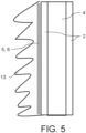
- Fig. 5 shows the insulating tube 2 of the gas insulated electric apparatus 1 in a schematic side view according to a further exemplary implementation.
- the permeation barrier 5 respectively the permeation layer 6 is arranged on the outer wall of the insulating tube 2.
- the permeation barrier 5 respectively the permeation layer 6 is covered by silicon sheds as epoxy based composite isolator 13, in particular for outdoor application for protecting the insulating tube 2 tube and for providing greater creeping distances.
- Fig. 6 shows the insulating tube 2 of the gas insulated electric apparatus 1 in a schematic top view according to a further exemplary implementation.
- the permeation barrier 5 respectively the permeation layer 6 is arranged on the inner wall of the insulating tube 2, whereby the insulating tube 2 is filled with an insulating fluid 12 such as for example oil.
- an insulating fluid 12 such as for example oil.
- a vacuum is provided within the insulating tube 2 housing an electrical sub-component.
- the insulating tube 2 is provided within an outer insulating tube 11, which also comprise a tube-like shape. Such wise the outer insulating tube 11 completely surrounding the insulating tube 2. A space between the outer insulating tube 11 and the insulating tube 2 is filled with the insulation gas 4. Further, the electric high voltage appliance 3 is provided between the outer insulating tube 11 and the insulating tube 2 i.e. in the space.
- the outer insulating tube 11 is surrounded by ambient atmosphere 10, such as for example air.
- the outer insulating tube 11 may also comprise a permeation barrier 5 respectively the permeation layer 6, or other respective layers as mentioned above.
Landscapes
- Engineering & Computer Science (AREA)
- Power Engineering (AREA)
- Chemical & Material Sciences (AREA)
- Inorganic Chemistry (AREA)
- Physics & Mathematics (AREA)
- Spectroscopy & Molecular Physics (AREA)
- Insulating Bodies (AREA)
- Laminated Bodies (AREA)
- Transformer Cooling (AREA)
Abstract
Description
- The invention relates to a gas insulated electric apparatus comprising an insulating tube, an electric high voltage appliance arranged inside the insulating tube and a permeation barrier, whereby the insulating tube contains an insulation gas comprising at least 70 % by volume of CO2 and/or N2 and comprising an elevated and pre-determined operating gas pressure level. The invention further relates to a method for manufacturing a gas insulated electric apparatus comprising an electric high voltage appliance, comprising the step of: Manufacturing an insulating tube.
- In gas insulated electric apparatuses such as medium and high voltage switchgears or control gears an electrical active part is arranged in a gas-tight insulating tube or housing. The insulating tube or housing defines an insulating space that is arranged to contain an insulation gas at an elevated pressure, which can be several bars. The insulating space separates the insulating tube from the electrical active part without letting electrical current pass through.
- The insulation gas serves as an electric insulation medium and prevents electric discharge between the insulating tube and the electrical components inside the insulating tube. Further, the insulation gas serves as a cooling medium for suppressing temperature rise due to electric current. In a switchgear which typically comprises a circuit breaker and/or a disconnector, the insulation gas also serves as an arc-extinguishing medium for extinguishing arcs that may occur at the switching operation. Conventionally, sulphur hexafluoride gas, SF6 or SF6 gas, has been widely used as insulation gas. However, in view of the known environmental drawbacks of SF6, the use of other insulation gases has been proposed, such as carbon dioxide, CO2, Nitrogen, N2, mixtures thereof or other gases.
- Generally, the insulating tube of the gas insulated electrical apparatuses is filled with the insulation gas up to a pre-determined operational rated gas pressure level before it is taken into operation. The pre-determined pressure level can be chosen depending on the insulation gas, switched current/voltage and/or the switching capacity of the electric apparatus. The pressure level is measured during the operation continuously or at pre-determined intervals.
- If the gas pressure level is below a pre-defined lowest acceptable pressure level, also called alarm level, an alarm is generated to the operator. If the alarm is generated, the insulating tube should be filled with insulation gas to the pre-determined operational gas pressure level. If the insulating tube is not replenished, there is a risk that the insulation gas pressure will continue to decrease and consequently operational disturbances are caused.
- Normally, the electrical apparatus has a pre-defined blocking pressure level, also named lock-out gas pressure level, and when the blocking pressure level is reached, the function of the gas insulated electric apparatus will be blocked and ceased. When the gas insulated electrical apparatus is a switchgear, it is usually configured to react in one of two ways: either the function of the gas insulated electric apparatus will be blocked such that it will not be possible to open or close an electric contact of the switchgear, or the electric contact will be forced open and stay open.
-
EP 3 416 178 A1 -
US 10 818 407 B2 -
EP 4 142 079 A1 - The refilling operation and monitoring of the alarms in the electrical apparatuses are time and labour consuming tasks. Therefore, there is a need to reduce service occasions while operational disturbances of gas insulated electrical apparatuses are effectively avoided.
- It is therefore an object of the invention to maintain properties of an insulation material of the insulating tube as best as possible for avoiding CO2 and/or N2 leakage.
- The object of the invention is solved by the features of the independent claims. Preferred implementations are detailed in the dependent claims.
- Thus, the object is solved by a gas insulated electric apparatus comprising an insulating tube, an electric high voltage appliance arranged inside and/or outside of the insulating tube, whereby
- the insulating tube comprises a permeation barrier,
- the insulating tube contains and/or is surrounded by an insulation gas comprising at least 70 % by volume of CO2 and/or N2 and comprising an elevated and pre-determined operating gas pressure level,
- the permeation barrier comprises polyvinyl alcohol, ethylene vinyl alcohol, aluminium oxide, silicon oxide and/or polyurethane.
- In order to lower the global warming potential, GWP, alternative isolation gas mixtures are used other than SF6, which contain molecules such as CO2 and/or N2 having a lower kinetic diameter and/or a higher solubility in the respective material of an insulating tube consisting in particular of epoxy based composite as insulator. Tests have demonstrated that CO2 and/or N2 alternative isolation gas mixtures permeate at high rates through such epoxy based insulating tube, which leads to a significant pressure drop and finally results in reduced dielectric and or current switching behaviour of the gas insulated electric apparatus respectively the in particular epoxy based composite manufactured insulating tube. In addition, H2O can permeate into the insulation space defined by the insulating tube and can lead directly or indirectly to decomposition of the insulation gas, to corrosion of components inside the gas insulated electric apparatus such as the electric high voltage appliance or to lower dielectric withstand of the insulating tube.
- Prior art insulating tubes typically comprise and/or the insulating tube comprises a material having a CO2 permeation coefficient at 20 °C of more than 1.0 cm3 * mm / (m2 * day * bar) and/or a CO2 solubility at 20 °C of at least 1.0 * 10-5 kmol / (m3 * kPa). Such material leads to significant CO2 and/or N2 pressure drop. By applying the proposed permeation barrier, the CO2 and/or N2 pressure drop is significantly reduced, in particular by at least 20, 50 or 80%. The term contains and/or is surrounded by the insulation gas means in particular that the insulating tube comprises the insulation gas arranged within the insulating tube and/or that the insulation gas is arranged outside the insulating tube, whereby, for example, the insulation gas is housed by an outer insulating tube housing the insulating tube as well. Preferably no insulation gas is present within the insulating tube.
- In sum, the proposes gas insulated electric apparatus consists of the insulating tube with the permeation barrier as layer of a particular thickness and material to decrease gas permeation through the insulating tube to a certain degree and therefore reduces a risk of accumulation of gas, in one implementation, inside the insulating tube, reduction of gas partial pressure outside of the insulating tube, partial discharge and destruction of the insulating tube itself due to pressure increase as a result of continuous permeation. Thereby, the permeation barrier can be applying, for example during a winding process of the insulating tube, as a first winding layer, as an intermediate layer and/or as a last winding layer.
- According to a preferred implementation, the permeation barrier is arranged within a wall, on an inside wall and/or an outside wall of the insulating tube. Preferably the permeation barrier covers at least 50%, 75%, 90% or the complete inside and/or outside wall of the insulating tube. Further preferably, the permeation barrier is arranged circumferentially surrounding and/or the permeation barrier circumferentially surrounds the electric high voltage appliance.
- In a further preferred implementation the permeation barrier comprises a permeation layer surrounded on at least one side by a flow promoter layer, a surface activation and/or primer layer, a carrier layer and/or a protective layer. The flow promoter layer, the surface activation and/or primer layer, and/or the protective layer can be arranged on an inside and/or on an outside of the permeation barrier and/or the permeation layer. The protective layer can be provided as solvent based epoxy layer, among others. The protective layer can be intended to prevent water absorption of the permeation layer and/or prevent chemical reaction of the insulation gas with the permeation layer. The carrier layer may comprise polymide, PI, polyethylene terephthalate, PET, (oriented)polypropylene, (O)PP, polyethylene naphthalate, PEN, or other suitable materials.
- Thus, a key point of the invention is therefore to provide a layer of in particular a low permeation material, LPM, having a very low permeation coefficient for the respective gas i.e. CO2 and/or N2 as permeation barrier. For allowing a simple implementation by using for example wide band strips or sheets as permeation barrier, the described solution proposes to provide on at least one side of the permeation layer the flow promoter layer and/or the surface activation and/or primer layer. Such way air bubbles and/or cracks leading to potential failure of the epoxy based composite insulator respectively insulating tube under dielectric or environmental stress can be effectively avoided, while a simple manufacturing of the permeation barrier and thus cost-effective manufacturing of the gas insulated electric apparatus becomes available. In addition, the proposed solution avoids permeation through the epoxy based composite insulator respectively insulating tube, which avoids a pressure drop within the insulating tube resulting in stable and reliable dielectric and or current switching behaviour.
- The insulating tube, sometimes also referred to as enclosure, preferably comprises a tube-like or conical tube-like shape and/or is preferably hermetically sealed. Thus, the insulation gas preferably completely surrounds the electric high voltage appliance. The permeation barrier arranged within the insulating tube means in particular that the permeation barrier is encapsulated within the insulating tube, thus for example not visible from an outside or inside of the insulating tube. The insulating tube can be filled with CO2 and/or N2 as insulation gas by at least 70 % by volume, but may also be completely filled with CO2 and/or N2. The remainder up to 100 % by volume in the insulation gas may comprise for example oxygen O2 or another gas to an extent of less than 30 % by volume. Preferably, the operating gas pressure level is from 0.7 or 1.0 MPa up to 1.2 MPa or 1.4.
- In one implementation, the insulating gas comprises 2 to 15, in particular 3 to 5, volume % of C4-fluoronitrile and 2 to 15, in particular 4 to 11, volume % of O2, and further comprises CO2 as carrier gas. More specifically, CO2 can be present in an amount of at least 70 volume %. The term C4-fluoronitrile preferably refers to heptafluoroisobutyronitrile. The insulating gas may comprise, in addition to CO2, for example an organofluorine compound, for example a fluoronitrile, and in particular a perfluoronitrile, a C4-fluoronitrile and/or a heptafluoroisobutyronitrile. More particularly, the fluoronitrile can be a perfluoroalkylnitrile, specifically perfluoroacetonitrile, perfluoropropionitrile (C2F5CN) and/or perfluorobutyronitrile (C3F7CN). Preferably, the fluoronitrile can be perfluoroisobutyronitrile (according to the formula (CF3)2CFCN) and/or perfluoro-2- methoxypropanenitrile (according to the formula CF3CF(OCF3)CN). Of these, perfluoroisobutyronitrile is particularly preferred due to its low toxicity.
- The permeation barrier preferably extends across the complete lateral inner and/or outer surface of the insulating tube. Further, the permeation layer is preferably surrounded on its complete or at least on it partial surface with the flow promoter layer and/or the surface activation and/or primer layer. Thereby, the flow promoter layer and/or the surface activation and/or primer layer can be provided on one side of the permeation layer or on both sides of the permeation layer. The insulating tube can be sealed with one or more sealings, for example made of a polymeric material of various types, for example nitrile rubber, NBR, ethylene propylene diene monomer rubber, EPDM, and/or isobutylene isoprene rubber, (X)IIR, rubber, but not limited to these materials.
- As described, the permeation barrier and/or preferably the permeation layer comprises polyvinyl alcohol, PVOH, and/or ethylene vinyl alcohol, EVOH, aluminium oxide, in particular aluminium oxide foil, silicon oxide and/or polyurethane. PVOH and/or EVOH provides an CO2 and/or N2 but also an oxygen or hydrocarbon barrier. PVOH and/or EVOH is advantageous in that it is highly transparent, weather resistant, oil and solvent resistant, flexible, moldable, recyclable, and printable. PVOH and/or EVOH can be applied by coextruding or laminating. The permeation barrier and/or permeation layer may comprise a thickness of 0,0001, 0,0005, 0,001, 0,01, 0,1, 0,5, 1, 2, 5 or 10 mm. Aluminium oxide or aluminium oxide foil may have a thickness of 0,016 or 0,024 mm. Besides that other materials can be used for mitigating permeation of the insulation gas. The surface activation layer may result from plasma and/or chemical threating and/or chemical bonding the permeation layer. As primer any suitable material may be used for priming the insulating tube and the permeation layer.
- Polyvinyl alcohol, PVOH, PVA, or PVAI, can be understood as a water-soluble synthetic polymer and/or having the chemical formula (C2H4O)x. Ethylene vinyl alcohol can be understood as a formal copolymer of ethylene and vinyl alcohol and/or having the chemical formula (C2H4O-C2H4)x. Aluminium oxide, or aluminium(III) oxide, can be understood as a chemical compound of aluminium and oxygen with the chemical formula Al2O3. Polyurethane, often abbreviated as PUR and PU, can be understood as a class of polymers composed of organic units joined by carbamate (urethane) links. PVOH, PU and/or EVOH are preferably applied by spraying. SiOx compound and/or aluminium oxide are preferably applied by chemical vapor deposition, in particular by plasma impulse. PVOH, PU and/or EVOH can be integrated with or without the surface activation and/or primer layer. Silicone oxide, in particular a SiOx compound, and/or aluminium oxide can be integrated with the surface activation and/or primer layer, but preferably not without the carrier layer and/or the surface activation and/or primer layer.
- In a further preferred limitation the permeation barrier, the permeation layer, the flow promoter layer and/or the surface activation and/or primer layer are provided as a sheet and/or as a strip, preferably as preferably overlapping wrapped strips, preferably overlapping in axial and/or circumferential direction. The strips can be provided as wide band strips. Preferably, the sheets and/or the strips overlap across the complete axial and/or circumferential extension of the respective layer. In circumferential extension the sheet and/or the strip may comprise no gap, a gap or may overlap. Alternatively, the permeation barrier, the permeation layer, the flow promoter layer and/or the surface activation and/or primer layer can be applied by spraying, in particular on an inner and/or outer surface respectively wall.
- In another referred implementation the gas insulated electric apparatus comprises the flow promoter layer, whereby the flow promoter layer comprises a fleece and/or mesh. The fleece and/or mesh may comprise polyester, aramid, a synthetic fibre, a textile fibre and/or any mixture thereof. Further materials may comprise polyamide such as nylon, Kevlar, Nomex, trogamide, and combinations of polyester, polyamide, and polypropylene. The flow promoter layer may comprise a thickness of 0,1, 0,3, 0,5, 1 or 2mm.
- In a further preferred implementation the permeation barrier is arranged within the insulating tube adjacent to an inside of the insulating tube and/or closer to the inside than to the outside of the insulating tube. Having the permeation barrier close to the inside bears the advantage that only very few radial material exists within the insulating tube for saturating the insulating gas therein. Thus, the permeation barrier is preferably arranged as close as possible to the inside of the insulating tube.
- It is further preferred that the electric high voltage appliance is arranged inside the insulating tube and that the insulating tube circumferentially surrounds the electric high voltage appliance. Alternatively, the gas insulated electric apparatus may comprises an outer insulating tube, whereby the electric high voltage appliance is arranged outside the insulating tube and inside the outer insulating tube. The outer insulating tube may comprise a tube like shape. A space between the insulating tube and the outer insulating tube may be filled with the insulating gas, such as for example CO2 and/or N2 mixed with C4-FN and O2. The insulating tube may be filled with an insulating fluid, such for example oil or gas, or may comprise a vacuum with an electrical sub-component. The outer insulating tube may also comprise a permeation barrier and/or another layer as described in the application.
- According to a further preferred implementation the gas insulated electric apparatus comprises a plurality of permeation barriers arranged in particular distant to each other on and/or within the insulating tube. Having a plurality of permeation barriers and/or a permeation barrier with higher thickness results in lower permeation. Thus, a limit-thickness of the a permeation barrier and/or number of permeation barriers may be necessary to ensure a specific leakage rate is not exceeded such that a specified lifetime before a refill with insulating gas is required can be ensured.
- In another preferred implementation the permeation barrier comprises polyvinyl alcohol and/or ethylene vinyl alcohol and a thickness ≥ 5 and ≤ 450 µm, in particular ≥ 10 and ≤ 300 µm, in particular ≥ 50 and ≤ 200 µm. In a further preferred implementation the permeation barrier comprises polyurethane and a thickness ≥ 10 and ≤ 500 µm, in particular ≥ 50 and ≤ 300 µm. In another preferred implementation the permeation barrier comprises polyvinyl alcohol, ethylene vinyl alcohol and/or polyurethane and is covered by a solvent based epoxy paint layer, in particular a solvent based epoxy layer, having a dry film thickness ≥ 50 and ≤ 150 µm, in particular ≥ 75 and ≤ 125 µm.
- In another preferred implementation the electric high voltage appliance is provided as a high voltage interrupter. The electric apparatus can be provided as a gas insulated live tank circuit breaker, as a gas insulated dead tank circuit breaker, as a bushing or as a gas insulated switchgear. Alternatively, the electric apparatus can be provided as a control gear such as a gas insulated instrument transformer. In either one of these apparatuses it will be of great value to have an apparatus that will have a reliable functionality for many years without requiring refilling of insulation gas.
- In a further preferred implementation the electric apparatus is provided as an outdoor gas insulated electric apparatus. In this respect the insulating tube can be covered with silicone sheds. Alternatively, in case the insulating tube is provided as epoxy based composite insulator, layer of the insulator can be imbedded within the silicone sheds following the same principles described.
- The object is further solved by a method for manufacturing a gas insulated electric apparatus comprising an electric high voltage appliance, comprising the steps of:
- Manufacturing an insulating tube in particular for arranging the electric high voltage appliance therein, and
- Applying, during manufacturing, a permeation barrier to the insulating tube for in particular circumferentially surrounding the electric high voltage appliance, whereby
- The insulating tube is preferably manufactured by impregnation of a liquid epoxy on a core having a negative form of an inner surface of the insulating tube. The liquid epoxy flows and should fill all cavities. The proposed flow promoter layer and/or surface activation and/or primer layer helps to avoid that air bubbles remain and/or cracks arise, which otherwise may lead to potential failure of the epoxy based composite insulator respectively insulating tube under dielectric or environmental stress.
- According to a preferred implementation the insulating tube comprises an epoxy based composite isolator, the epoxy based composite isolator comprises wet wound fibres and/or the manufacturing comprises vacuum impregnating the epoxy based composite isolator.
- In another preferred implementation the method comprises the step of:
Applying, during manufacturing, first a flow promoter layer and/or a surface activation and/or a primer layer, second the permeation barrier and/or a permeation layer, and/or third another promoter layer and/or another surface activation and/or primer layer. - In a further preferred implementation the method comprises the step of:
Applying, during manufacturing, first the permeation barrier and/or the permeation layer and second a protective layer. - In another preferred implementation the method comprises the step of:
Applying, during manufacturing, first the permeation barrier and/or the permeation layer onto a carrier layer. - In a further preferred implementation the method comprises the steps of:
- Filling the insulating tube with an insulation gas comprising at least 70 % by volume of CO2 and/or N2 and comprising an elevated and pre-determined operating gas pressure level, and
hermetically sealing the insulating tube. - Further implementations and advantages of the method are directly and unambiguously derived by the person skilled in the art from the apparatus as described before.
- These and other aspects of the invention will be apparent from and elucidated with reference to the implementations described hereinafter.
- In the drawings:
-
Fig. 1a shows a gas insulated electric apparatus with an enlarged part of an insulating tube of the apparatus in a schematic top view according to an exemplary implementation, -
Fig. 1b shows an enlarged part of the insulating tube of the apparatus in a schematic top view according to a further exemplary implementation, -
Fig. 2 shows an enlarged parts of insulating tubes of the apparatus in a schematic top view according to further exemplary implementations, -
Fig. 3 shows the gas insulated electric apparatus in a schematic side view according to the exemplary implementations, -
Fig. 4a to 4f each show an enlarged part of the insulating tube of the apparatus in a schematic top view according to further exemplary implementations, -
Fig. 5 shows the insulating tube of the gas insulated electric apparatus in a schematic side view according to a further exemplary implementation, and -
Fig. 6 shows the insulating tube of the gas insulated electric apparatus in a schematic top view according to a further exemplary implementation. -
Fig. 1 shows a gas insulatedelectric apparatus 1 according to an exemplary implementation in a schematic top view. The gas insulated electric apparatus can be provided a gas insulated circuit breaker, finding its application for example as a gas insulated live tank circuit breaker, a bushing or a gas insulated dead tank circuit breaker. Alternatively, the gas insulated electric apparatus may be a gas insulated switchgear, or a control gear such as a gas insulated instrument transformer. The gas insulated apparatus can be suitable for use outdoors. - The gas insulated
electric apparatus 1 generally comprises an electrically insulating insulatingtube 2 having a shape of a tube shown in top view with a wall made of a polymeric material and/or a composite material, in particular an epoxy based composite material as insulator capable to resist a pressure inside the insulatingtube 1. The insulatingtube 2 is typically manufacturing by wet-wound fibers and/or in a vacuum impregnation process, thus resulting in a high mechanical strength and good dielectric properties of the insulator. Inside the insulatingtube 2 arranged is an electrichigh voltage appliance 3, which is provided as a high voltage interrupter and is only schematically shown inFig. 1 . The insulatingtube 2 is hermetically sealed and filled with aninsulation gas 4, which comprises at least 70 % by volume of CO2 and/or N2 at an elevated and pre-determined operating gas pressure level ranging from 0.7 or 1.0 MPa up to 1.2 or 1.4 MPa. - On the insulating tube, for example on an inside and/or outside wall of the insulating tube, a
permeation barrier 5 is provided, which circumferentially surrounds the electrichigh voltage appliance 3. Thepermeation barrier 5 comprises polyvinyl alcohol, ethylene vinyl alcohol, aluminium oxide, silicone oxide and/or polyurethane, Circumferentially, as shown inFig. 2 in the top, thepermeation barrier 5 can have no circumferential gap, can have a circumferential gap, as shown inFig. 2 in the middle, or can be arranged circumferentially overlapping, as shown inFig. 2 on the bottom. Without gap, thepermeation barrier 5 fully respectively completely extends around the electrichigh voltage appliance 3. The gap might be 1, 2, 5 or 10 mm wide. In axial direction, depicted inFig. 3 , thepermeation barrier 5 may also cover the complete axial extension of the insulatingtube 2, as shown on the left side ofFig. 3 . Alternatively, as shown on the right side ofFig. 3 ,permeation barrier 5 can be arranged in an overlapping manner. Overlapping means that in radial direction the electrichigh voltage appliance 3 is always surrounded by any of thevarious permeation barriers 5. - Generally, the
permeation barrier 5 may be provided as a sheet and/or as a strip, for example as said overlapping wrapped strips. Also, as depicted inFig. 1b , multiple layers ofindividual permeation barriers 5 can be present within the insulatingtube 2 arranged distant to each other. Thereby, as shown inFig. 1 , thepermeation barrier 5 is arranged inside the insulatingtube 2 adjacent to an inside respectively inner surface of the insulatingtube 2. In other words, thepermeation barrier 5 is preferably provided closer to the inside than to the outside of the insulatingtube 2. The outside respectively outer surface of the insulatingtube 2, i.e. the surface facing the surroundings of the insulatingtube 2, can comprise a plurality of sheds, not shown. The sheds may extend along the whole or partial length of the insulating tube. - When manufacturing the insulating
tube 2, epoxy composites may be placed around a core representing a negative form of the inner surface of the designated insulatingtube 2, followed by placing thepermeation barrier 5 onto the epoxy composites and again followed by another layer of epoxy composites up to the designated outer surface of the designated insulatingtube 2. When the insulatingtube 2 is cured, the core can be removed and the electrichigh voltage appliance 3 can be placed within the insulatingtube 2. The insulatingtube 2 is sealed and filled with theinsulation gas 4 up to the operating gas pressure level. - Referring again to
Fig. 1 ,permeation barrier 5 comprises a thin layer of a Low Permeation Material, LPM, having a very low permeation coefficient for therespective insulation gas 4 as permeation layer 6. Said permeation layer 6 can be applied once to form a single layer or multiple times to increase effectiveness if very low permeation rates are required. As explained before, in simplest implementation the permeation layer 6 can be formed of a sheet of LPM being wrapped once around the insulatingtube 2 during manufacturing the same. For practical reasons, the permeation layer 6 can be made of wide band strips instead of a single sheet of LPM. These strips are wrapped with or without overlap depending on the permeation performance needed. The permeation layer 6 consists of polyvinyl alcohol and/or ethylene vinyl alcohol, PVOH and/or EVOH, and/or can be provided as aluminium oxide or silicon oxide applied on a foil, or other materials suitable for avoiding permeation of the insulatinggas 4. - In order to achieve a sufficient impregnation and/or adhesion with such sheets or wide strips in composite materials such as epoxy based composite insulating tubes, potentially resulting in air bubbles or cracks leading to failure of the
insulation insulating tube 2 under dielectric or environmental stress, impregnation is improved by providing anflow promoter layer 7, while adhesion is improved by providing a surface activation and/or primer layer 8. Thus, either both theflow promoter layer 7 and the surface activation and/or primer layer 8 can be present, while also only one of theflow promoter layer 7 and the surface activation and/or primer layer 8 may be present. Also, only one side of both sides of the permeation layer 6 can be equipped with theflow promoter layer 7 and/or the surface activation and/or primer layer 8. - The
flow promoter layer 7 comprises fleece and/or mesh, such as for example polyester, aramid, textiles, or any combination of mixture thereof. The thickness of thepromoter layer 7 may range between 0,3 to 2mm, preferably 1mm. The surface activation and/or primer layer 8 can be applied by plasma threating, chemical bonding and/or chemical threating the permeation layer 6 for activating the surface of the permeation layer 6. The thickness of the surface activation and/or primer layer 8 may range from a 0,5 mm to 1 mm, for example 1 µm. The permeation layer 6 may comprise a thickness of 0,0001, 0,0005, 0,001, 0,01, 0,1, 0,5, 1, 2, 5 or 10 mm. -
Fig. 4a to 4e each show an enlarged part of the insulatingtube 2 of theapparatus 1 in a schematic top view according to further exemplary implementations.Fig. 4a shows an implementation where thepermeation barrier 5 respectively the permeation layer 6 is provided on an inner surface wall of the insulatingtube 2, whileFig. 4b shows an implementation where thepermeation barrier 5 respectively the permeation layer 6 is provided on an outer surface wall of the insulatingtube 2. -
Fig. 4c shows an implementation where thepermeation barrier 5 respectively the permeation layer 6 is again provided on the inner surface wall of the insulatingtube 2, whereby thepermeation barrier 5 respectively the permeation layer 6 is circumferentially and completely covered by aprotective layer 9. Such way thepermeation barrier 5 respectively the permeation layer 6 is radially arranged between the insulatingtube 2 and theprotective layer 9. Saidprotective layer 9 is provided as a solvent based epoxy layer. In an analogous manner,Fig. 4d shows an implementation where thepermeation barrier 5 respectively the permeation layer 6 is provided on the outer surface wall of the insulatingtube 2, whereby thepermeation barrier 5 respectively the permeation layer 6 is circumferentially and completely covered by theprotective layer 9. -
Fig. 4e shows an implementation where thepermeation barrier 5 respectively the permeation layer 6 is arranged radially inside the insulatingtube 2, while on an inside circumferentially covered by a carrier layer 14, which is provided as foil. Such carrier layer 14 is in particular advantageous for apermeation barrier 5 comprising aluminium oxide and silicon oxide.Fig. 4f again shows an implementation where thepermeation barrier 5 respectively the permeation layer 6 is arranged radially inside the insulatingtube 2 and covered with the carrier layer 14 towards the inside. Besides the combination ofpermeation barrier 5 respectively permeation layer 6 and carrier layer 14 is on both sides covered with apromoter layer 7 and/or surface activation and/or primer layer 8. -
Fig. 5 shows the insulatingtube 2 of the gas insulatedelectric apparatus 1 in a schematic side view according to a further exemplary implementation. Thepermeation barrier 5 respectively the permeation layer 6 is arranged on the outer wall of the insulatingtube 2. Thepermeation barrier 5 respectively the permeation layer 6 is covered by silicon sheds as epoxy basedcomposite isolator 13, in particular for outdoor application for protecting the insulatingtube 2 tube and for providing greater creeping distances. -
Fig. 6 shows the insulatingtube 2 of the gas insulatedelectric apparatus 1 in a schematic top view according to a further exemplary implementation. Thepermeation barrier 5 respectively the permeation layer 6 is arranged on the inner wall of the insulatingtube 2, whereby the insulatingtube 2 is filled with an insulating fluid 12 such as for example oil. Alternatively, a vacuum is provided within the insulatingtube 2 housing an electrical sub-component. - The insulating
tube 2 is provided within an outer insulatingtube 11, which also comprise a tube-like shape. Such wise the outer insulatingtube 11 completely surrounding the insulatingtube 2. A space between the outer insulatingtube 11 and the insulatingtube 2 is filled with theinsulation gas 4. Further, the electrichigh voltage appliance 3 is provided between the outer insulatingtube 11 and the insulatingtube 2 i.e. in the space. The outer insulatingtube 11 is surrounded byambient atmosphere 10, such as for example air. The outer insulatingtube 11 may also comprise apermeation barrier 5 respectively the permeation layer 6, or other respective layers as mentioned above. - While the invention has been illustrated and described in detail in the drawings and foregoing description, such illustration and description are to be considered illustrative or exemplary and not restrictive; the invention is not limited to the disclosed implementations. Other variations to be disclosed implementations can be understood and effected by those skilled in the art in practicing the claimed invention, from a study of the drawings, the disclosure, and the appended claims. In the claims, the word "comprising" does not exclude other elements or steps, and the indefinite article "a" or "an" does not exclude a plurality. The mere fact that certain measures are recited in mutually different dependent claims does not indicate that a combination of these measures cannot be used to advantage. Any reference signs in the claims should not be construed as limiting scope.
-
- 1
- electric apparatus
- 2
- insulating tube
- 3
- electric high voltage appliance
- 4
- insulation gas
- 5
- permeation barrier
- 6
- permeation layer
- 7
- promoter layer
- 8
- surface activation and/or primer layer
- 9
- protective layer
- 10
- atmosphere
- 11
- outer insulating tube
- 12
- insulating fluid
- 13
- epoxy based composite isolator
- 14
- carrier layer
Claims (15)
- A gas insulated electric apparatus (1) comprising an insulating tube (2), an electric high voltage appliance (3) arranged outside of the insulating tube (2), wherebythe insulating tube (2) comprises a permeation barrier (5),the insulating tube (2) is surrounded by an insulation gas (4) comprising at least 70 % by volume of CO2 and/or N2 and comprising an elevated and pre-determined operating gas pressure level, andthe permeation barrier (5) comprises polyvinyl alcohol, ethylene vinyl alcohol, aluminium oxide, silicon oxide and/or polyurethane.
- The gas insulated electric apparatus (1) of the previous claim, whereby the permeation barrier (5) is arranged within a wall, on an inside wall and/or on an outside wall of the insulating tube (2).
- The gas insulated electric apparatus (1) of any of the previous claims, whereby the permeation barrier (5) comprises a permeation layer (6) surrounded on at least one side by a flow promoter layer (7), a surface activation and/or primer layer (8), a protective layer (9) and/or a carrier layer (14).
- The gas insulated electric apparatus (1) of the previous claim, whereby the permeation barrier (5), the permeation layer (6), the flow promoter layer (7) and/or the surface activation and/or primer layer (8) are provided as a sheet and/or as a strip, preferably as preferably overlapping wrapped strips, preferably overlapping in axial and/or circumferential direction.
- The gas insulated electric apparatus (1) of any of the previous claims, comprising the flow promoter layer (7), whereby the flow promoter layer (7) comprises a fleece and/or mesh.
- The gas insulated electric apparatus (1) of any of the previous claims, whereby the permeation barrier (5) is arranged within the insulating tube (2) adjacent to an inside of the insulating tube (2) and/or closer to the inside than to the outside of the insulating tube (2).
- The gas insulated electric apparatus (1) of any of the previous claims, comprising an outer insulating tube (11), whereby the electric high voltage appliance (3) is arranged inside the outer insulating tube (11).
- The gas insulated electric apparatus (1) of any of the previous claims, comprising a plurality of permeation barriers (5) arranged in particular distant to each other on and/or within the insulating tube (2).
- The gas insulated electric apparatus (1) of any of the previous claims, whereby the permeation barrier (5) comprises polyvinyl alcohol and/or ethylene vinyl alcohol and a thickness ≥ 5 and ≤ 450 µm, in particular ≥ 10 and ≤ 300 µm, or the permeation barrier (5) comprises polyurethane and a thickness ≥ 5 and ≤ 650 µm, in particular ≥ 10 and ≤ 500 µm
- The gas insulated electric apparatus (1) of any of the previous claims, whereby the permeation barrier (5) comprises polyvinyl alcohol, ethylene vinyl alcohol and/or polyurethane and/or is covered by a protective layer (9), in particular a solvent based epoxy paint layer, having a dry film thickness ≥ 25 and ≤ 300 µm, in particular ≥ 50 and ≤ 150 µm.
- The gas insulated electric apparatus (1) according to any of the previous claims, wherein the electric high voltage appliance (3) is provided as a high voltage interrupter, whereby the electric apparatus (1) is provided as a gas insulated live tank circuit breaker, as a gas insulated dead tank circuit breaker, as a bushing or as a gas insulated switchgear, and/or whereby the electric apparatus (1) is provided as an outdoor gas insulated electric apparatus.
- Method for manufacturing a gas insulated electric apparatus (1) comprising an electric high voltage appliance (3), comprising the steps of:Manufacturing an insulating tube (2), andApplying, during manufacturing, a permeation barrier (5) to the insulating tube (2), wherebythe permeation barrier (5) comprises polyvinyl alcohol, ethylene vinyl alcohol, aluminium oxide, silicone oxide and/or polyurethane.
- Method according to the previous method claim, whereby the insulating tube (2) comprises an epoxy based composite isolator (13), the epoxy based composite isolator (13) comprises wet wound fibres and/or the manufacturing comprises vacuum impregnating the epoxy based composite isolator (13).
- Method comprising to any of the previous method claims, comprising the step of:
Applying, during manufacturing, first a flow promoter layer (7) and/or a surface activation and/or a primer layer (8), second the permeation barrier (5) and/or a permeation layer (6), and/or third another promoter layer (7) and/or another surface activation and/or primer layer (8). - Method comprising to any of the previous method claims, comprising the steps of:Surrounding the insulating tube (2) with an insulation gas (4) comprising at least 70 % by volume of CO2 and/or N2 and comprising an elevated and pre-determined operating gas pressure level, and preferablyhermetically sealing the insulating tube (2).
Priority Applications (1)
| Application Number | Priority Date | Filing Date | Title |
|---|---|---|---|
| EP24215582.8A EP4513691A3 (en) | 2023-02-24 | 2023-02-24 | Gas insulated electric apparatus |
Applications Claiming Priority (3)
| Application Number | Priority Date | Filing Date | Title |
|---|---|---|---|
| EP23707711.0A EP4508668A1 (en) | 2023-02-24 | 2023-02-24 | Gas insulated electric apparatus |
| PCT/EP2023/054726 WO2024175208A1 (en) | 2023-02-24 | 2023-02-24 | Gas insulated electric apparatus |
| EP24215582.8A EP4513691A3 (en) | 2023-02-24 | 2023-02-24 | Gas insulated electric apparatus |
Related Parent Applications (2)
| Application Number | Title | Priority Date | Filing Date |
|---|---|---|---|
| EP23707711.0A Division EP4508668A1 (en) | 2023-02-24 | 2023-02-24 | Gas insulated electric apparatus |
| EP23707711.0A Division-Into EP4508668A1 (en) | 2023-02-24 | 2023-02-24 | Gas insulated electric apparatus |
Publications (2)
| Publication Number | Publication Date |
|---|---|
| EP4513691A2 true EP4513691A2 (en) | 2025-02-26 |
| EP4513691A3 EP4513691A3 (en) | 2025-05-07 |
Family
ID=85384610
Family Applications (2)
| Application Number | Title | Priority Date | Filing Date |
|---|---|---|---|
| EP24215582.8A Pending EP4513691A3 (en) | 2023-02-24 | 2023-02-24 | Gas insulated electric apparatus |
| EP23707711.0A Pending EP4508668A1 (en) | 2023-02-24 | 2023-02-24 | Gas insulated electric apparatus |
Family Applications After (1)
| Application Number | Title | Priority Date | Filing Date |
|---|---|---|---|
| EP23707711.0A Pending EP4508668A1 (en) | 2023-02-24 | 2023-02-24 | Gas insulated electric apparatus |
Country Status (4)
| Country | Link |
|---|---|
| US (1) | US20260112867A1 (en) |
| EP (2) | EP4513691A3 (en) |
| CN (1) | CN120731475A (en) |
| WO (1) | WO2024175208A1 (en) |
Families Citing this family (1)
| Publication number | Priority date | Publication date | Assignee | Title |
|---|---|---|---|---|
| EP4648078A1 (en) | 2024-05-10 | 2025-11-12 | Hitachi Energy Ltd | Gas insulated electric apparatus |
Citations (3)
| Publication number | Priority date | Publication date | Assignee | Title |
|---|---|---|---|---|
| EP3416178A1 (en) | 2017-06-13 | 2018-12-19 | ABB Schweiz AG | Gas insulated electric apparatus with means to prevent gas leakage |
| US10818407B2 (en) | 2014-12-12 | 2020-10-27 | Abb Schweiz Ag | Apparatus for the generation, distribution and/or usage of electrical energy and component for such an apparatus |
| EP4142079A1 (en) | 2021-08-27 | 2023-03-01 | Hitachi Energy Switzerland AG | Gas insulated electric apparatus |
Family Cites Families (6)
| Publication number | Priority date | Publication date | Assignee | Title |
|---|---|---|---|---|
| JPS60125276A (en) * | 1983-12-07 | 1985-07-04 | Aichi Electric Mfg Co Ltd | Surface treatment of outer case of electric machinery |
| JPH08306281A (en) * | 1995-03-08 | 1996-11-22 | Fuji Electric Co Ltd | Vacuum valve for vacuum circuit breaker |
| US9074685B2 (en) * | 2010-02-26 | 2015-07-07 | GM Global Technology Operations LLC | Extruded tube welded vessel liner with injection molded end caps |
| EP2960053A1 (en) * | 2014-06-24 | 2015-12-30 | Inergy Automotive Systems Research (Société Anonyme) | Plastic liner for a composite pressure vessel |
| CN109449813A (en) * | 2018-12-28 | 2019-03-08 | 南通苏源恒炫电气有限公司 | A kind of highland and severe cold type solid-state insulated switchgear |
| CN113272927B (en) * | 2018-12-31 | 2022-10-21 | 日立能源瑞士股份公司 | Circuit breaker housing with integrated feedthrough |
-
2023
- 2023-02-24 EP EP24215582.8A patent/EP4513691A3/en active Pending
- 2023-02-24 EP EP23707711.0A patent/EP4508668A1/en active Pending
- 2023-02-24 CN CN202380094617.1A patent/CN120731475A/en active Pending
- 2023-02-24 WO PCT/EP2023/054726 patent/WO2024175208A1/en not_active Ceased
- 2023-02-24 US US19/152,638 patent/US20260112867A1/en active Pending
Patent Citations (3)
| Publication number | Priority date | Publication date | Assignee | Title |
|---|---|---|---|---|
| US10818407B2 (en) | 2014-12-12 | 2020-10-27 | Abb Schweiz Ag | Apparatus for the generation, distribution and/or usage of electrical energy and component for such an apparatus |
| EP3416178A1 (en) | 2017-06-13 | 2018-12-19 | ABB Schweiz AG | Gas insulated electric apparatus with means to prevent gas leakage |
| EP4142079A1 (en) | 2021-08-27 | 2023-03-01 | Hitachi Energy Switzerland AG | Gas insulated electric apparatus |
Also Published As
| Publication number | Publication date |
|---|---|
| WO2024175208A1 (en) | 2024-08-29 |
| EP4513691A3 (en) | 2025-05-07 |
| US20260112867A1 (en) | 2026-04-23 |
| CN120731475A (en) | 2025-09-30 |
| EP4508668A1 (en) | 2025-02-19 |
Similar Documents
| Publication | Publication Date | Title |
|---|---|---|
| RU2568185C2 (en) | Subsurface unit of electric fuses | |
| US20240372339A1 (en) | Gas insulated electric apparatus | |
| US4088830A (en) | Electrical cable with insulated and braid covered conductors and perforated polyolefin armor | |
| US20260112867A1 (en) | Gas insulated electric apparatus | |
| US4096351A (en) | Insulated and braid covered electrical conductor for use in gassy oil wells | |
| US10818407B2 (en) | Apparatus for the generation, distribution and/or usage of electrical energy and component for such an apparatus | |
| EP3416178B1 (en) | Gas insulated electric apparatus with means to prevent gas leakage | |
| WO2012048121A1 (en) | Solid-core surge arrester | |
| KR20010023988A (en) | Insulation for a conductor | |
| CA2381423C (en) | Flow-through cable | |
| FI75686C (en) | KANTBELAGD CAPACITOR ELECTRODES. | |
| US4956742A (en) | Switch gear | |
| EP4648078A1 (en) | Gas insulated electric apparatus | |
| CA1183916A (en) | High voltage capability electrical coils insulated with materials containing sf.sub.6 gas | |
| JP5044345B2 (en) | Switchgear | |
| EP0678959A1 (en) | Connecting portion-covering member | |
| EP1953771A1 (en) | An electric insulation element, a bushing provided therewith, and a method of producing such an element | |
| JP2003217373A (en) | Composite insulator, insulator-type circuit breaker and insulator-type lightning arrester using the same | |
| US11515697B2 (en) | Sealing end for high-voltage cables | |
| KR20250007670A (en) | Reinforced composite wrapped surge arrester and methods of providing same | |
| EP4712109A1 (en) | Fine graded condenser cores for bushings | |
| JP7263615B2 (en) | Disconnector unit with vacuum valve and insulating housing | |
| WO2024199628A1 (en) | Seal for a gas insulated high or medium voltage device | |
| BRPI0618803B1 (en) | Mica Reinforced Insulation Sleeve, Method for Producing a Mica Reinforced Insulation Sleeve, Use of an Insulation Sleeve and Production Method for an Electric Machine | |
| SU1265903A1 (en) | Arc-quenching tube of tubular protector |
Legal Events
| Date | Code | Title | Description |
|---|---|---|---|
| PUAI | Public reference made under article 153(3) epc to a published international application that has entered the european phase |
Free format text: ORIGINAL CODE: 0009012 |
|
| STAA | Information on the status of an ep patent application or granted ep patent |
Free format text: STATUS: THE APPLICATION HAS BEEN PUBLISHED |
|
| AC | Divisional application: reference to earlier application |
Ref document number: 4508668 Country of ref document: EP Kind code of ref document: P |
|
| AK | Designated contracting states |
Kind code of ref document: A2 Designated state(s): AL AT BE BG CH CY CZ DE DK EE ES FI FR GB GR HR HU IE IS IT LI LT LU LV MC ME MK MT NL NO PL PT RO RS SE SI SK SM TR |
|
| REG | Reference to a national code |
Ref country code: DE Ref legal event code: R079 Free format text: PREVIOUS MAIN CLASS: H02B0013055000 Ipc: H01H0033560000 |
|
| PUAL | Search report despatched |
Free format text: ORIGINAL CODE: 0009013 |
|
| RIN1 | Information on inventor provided before grant (corrected) |
Inventor name: KAUFMANN, BENJAMIN Inventor name: WEGMANN, JONAS Inventor name: TEPPATI, VALERIA Inventor name: FREI, PETER Inventor name: HENGSTLER, JOHANNES Inventor name: GATZSCHE, MICHAEL Inventor name: DONZEL, LISE Inventor name: BOEHM, MORITZ Inventor name: EHRLER, ISABELL |
|
| AK | Designated contracting states |
Kind code of ref document: A3 Designated state(s): AL AT BE BG CH CY CZ DE DK EE ES FI FR GB GR HR HU IE IS IT LI LT LU LV MC ME MK MT NL NO PL PT RO RS SE SI SK SM TR |
|
| RIC1 | Information provided on ipc code assigned before grant |
Ipc: H02B 13/055 20060101ALI20250328BHEP Ipc: H02B 13/045 20060101ALI20250328BHEP Ipc: H02B 13/01 20060101ALI20250328BHEP Ipc: H01B 3/40 20060101ALI20250328BHEP Ipc: H01H 33/56 20060101AFI20250328BHEP |
|
| STAA | Information on the status of an ep patent application or granted ep patent |
Free format text: STATUS: REQUEST FOR EXAMINATION WAS MADE |
|
| 17P | Request for examination filed |
Effective date: 20251107 |