EP4513662A1 - Battery and electronic device - Google Patents
Battery and electronic device Download PDFInfo
- Publication number
- EP4513662A1 EP4513662A1 EP23890368.6A EP23890368A EP4513662A1 EP 4513662 A1 EP4513662 A1 EP 4513662A1 EP 23890368 A EP23890368 A EP 23890368A EP 4513662 A1 EP4513662 A1 EP 4513662A1
- Authority
- EP
- European Patent Office
- Prior art keywords
- housing
- insulating member
- battery
- battery according
- tab
- Prior art date
- Legal status (The legal status is an assumption and is not a legal conclusion. Google has not performed a legal analysis and makes no representation as to the accuracy of the status listed.)
- Pending
Links
Images




Classifications
-
- H—ELECTRICITY
- H01—ELECTRIC ELEMENTS
- H01M—PROCESSES OR MEANS, e.g. BATTERIES, FOR THE DIRECT CONVERSION OF CHEMICAL ENERGY INTO ELECTRICAL ENERGY
- H01M50/00—Constructional details or processes of manufacture of the non-active parts of electrochemical cells other than fuel cells, e.g. hybrid cells
- H01M50/50—Current conducting connections for cells or batteries
- H01M50/572—Means for preventing undesired use or discharge
- H01M50/584—Means for preventing undesired use or discharge for preventing incorrect connections inside or outside the batteries
- H01M50/588—Means for preventing undesired use or discharge for preventing incorrect connections inside or outside the batteries outside the batteries, e.g. incorrect connections of terminals or busbars
-
- H—ELECTRICITY
- H01—ELECTRIC ELEMENTS
- H01M—PROCESSES OR MEANS, e.g. BATTERIES, FOR THE DIRECT CONVERSION OF CHEMICAL ENERGY INTO ELECTRICAL ENERGY
- H01M50/00—Constructional details or processes of manufacture of the non-active parts of electrochemical cells other than fuel cells, e.g. hybrid cells
- H01M50/10—Primary casings; Jackets or wrappings
- H01M50/172—Arrangements of electric connectors penetrating the casing
- H01M50/174—Arrangements of electric connectors penetrating the casing adapted for the shape of the cells
- H01M50/176—Arrangements of electric connectors penetrating the casing adapted for the shape of the cells for prismatic or rectangular cells
-
- H—ELECTRICITY
- H01—ELECTRIC ELEMENTS
- H01M—PROCESSES OR MEANS, e.g. BATTERIES, FOR THE DIRECT CONVERSION OF CHEMICAL ENERGY INTO ELECTRICAL ENERGY
- H01M10/00—Secondary cells; Manufacture thereof
- H01M10/04—Construction or manufacture in general
- H01M10/0431—Cells with wound or folded electrodes
-
- H—ELECTRICITY
- H01—ELECTRIC ELEMENTS
- H01M—PROCESSES OR MEANS, e.g. BATTERIES, FOR THE DIRECT CONVERSION OF CHEMICAL ENERGY INTO ELECTRICAL ENERGY
- H01M10/00—Secondary cells; Manufacture thereof
- H01M10/60—Heating or cooling; Temperature control
- H01M10/65—Means for temperature control structurally associated with the cells
- H01M10/655—Solid structures for heat exchange or heat conduction
- H01M10/6554—Rods or plates
-
- H—ELECTRICITY
- H01—ELECTRIC ELEMENTS
- H01M—PROCESSES OR MEANS, e.g. BATTERIES, FOR THE DIRECT CONVERSION OF CHEMICAL ENERGY INTO ELECTRICAL ENERGY
- H01M50/00—Constructional details or processes of manufacture of the non-active parts of electrochemical cells other than fuel cells, e.g. hybrid cells
- H01M50/20—Mountings; Secondary casings or frames; Racks, modules or packs; Suspension devices; Shock absorbers; Transport or carrying devices; Holders
- H01M50/204—Racks, modules or packs for multiple batteries or multiple cells
- H01M50/207—Racks, modules or packs for multiple batteries or multiple cells characterised by their shape
- H01M50/209—Racks, modules or packs for multiple batteries or multiple cells characterised by their shape adapted for prismatic or rectangular cells
-
- H—ELECTRICITY
- H01—ELECTRIC ELEMENTS
- H01M—PROCESSES OR MEANS, e.g. BATTERIES, FOR THE DIRECT CONVERSION OF CHEMICAL ENERGY INTO ELECTRICAL ENERGY
- H01M50/00—Constructional details or processes of manufacture of the non-active parts of electrochemical cells other than fuel cells, e.g. hybrid cells
- H01M50/20—Mountings; Secondary casings or frames; Racks, modules or packs; Suspension devices; Shock absorbers; Transport or carrying devices; Holders
- H01M50/218—Mountings; Secondary casings or frames; Racks, modules or packs; Suspension devices; Shock absorbers; Transport or carrying devices; Holders characterised by the material
- H01M50/22—Mountings; Secondary casings or frames; Racks, modules or packs; Suspension devices; Shock absorbers; Transport or carrying devices; Holders characterised by the material of the casings or racks
- H01M50/222—Inorganic material
- H01M50/224—Metals
-
- H—ELECTRICITY
- H01—ELECTRIC ELEMENTS
- H01M—PROCESSES OR MEANS, e.g. BATTERIES, FOR THE DIRECT CONVERSION OF CHEMICAL ENERGY INTO ELECTRICAL ENERGY
- H01M50/00—Constructional details or processes of manufacture of the non-active parts of electrochemical cells other than fuel cells, e.g. hybrid cells
- H01M50/50—Current conducting connections for cells or batteries
- H01M50/543—Terminals
- H01M50/547—Terminals characterised by the disposition of the terminals on the cells
- H01M50/55—Terminals characterised by the disposition of the terminals on the cells on the same side of the cell
-
- H—ELECTRICITY
- H01—ELECTRIC ELEMENTS
- H01M—PROCESSES OR MEANS, e.g. BATTERIES, FOR THE DIRECT CONVERSION OF CHEMICAL ENERGY INTO ELECTRICAL ENERGY
- H01M50/00—Constructional details or processes of manufacture of the non-active parts of electrochemical cells other than fuel cells, e.g. hybrid cells
- H01M50/50—Current conducting connections for cells or batteries
- H01M50/543—Terminals
- H01M50/552—Terminals characterised by their shape
- H01M50/553—Terminals adapted for prismatic, pouch or rectangular cells
- H01M50/557—Plate-shaped terminals
-
- H—ELECTRICITY
- H01—ELECTRIC ELEMENTS
- H01M—PROCESSES OR MEANS, e.g. BATTERIES, FOR THE DIRECT CONVERSION OF CHEMICAL ENERGY INTO ELECTRICAL ENERGY
- H01M50/00—Constructional details or processes of manufacture of the non-active parts of electrochemical cells other than fuel cells, e.g. hybrid cells
- H01M50/50—Current conducting connections for cells or batteries
- H01M50/572—Means for preventing undesired use or discharge
- H01M50/574—Devices or arrangements for the interruption of current
- H01M50/583—Devices or arrangements for the interruption of current in response to current, e.g. fuses
-
- Y—GENERAL TAGGING OF NEW TECHNOLOGICAL DEVELOPMENTS; GENERAL TAGGING OF CROSS-SECTIONAL TECHNOLOGIES SPANNING OVER SEVERAL SECTIONS OF THE IPC; TECHNICAL SUBJECTS COVERED BY FORMER USPC CROSS-REFERENCE ART COLLECTIONS [XRACs] AND DIGESTS
- Y02—TECHNOLOGIES OR APPLICATIONS FOR MITIGATION OR ADAPTATION AGAINST CLIMATE CHANGE
- Y02E—REDUCTION OF GREENHOUSE GAS [GHG] EMISSIONS, RELATED TO ENERGY GENERATION, TRANSMISSION OR DISTRIBUTION
- Y02E60/00—Enabling technologies; Technologies with a potential or indirect contribution to GHG emissions mitigation
- Y02E60/10—Energy storage using batteries
Definitions
- the present invention provides a battery and an electronic device, improving capacity density of the battery.
- a side of the insulating member away from the housing is provided with a mounting groove, the mounting hole is located at a bottom of the mounting groove, and the connecting sheet is disposed in the mounting groove and covers the mounting hole.
- a shape of the insulating member is matched with a shape of the notch, and the insulating member is clamped at the notch.
- edges of both opposite sides of the insulating member are provided with sliding grooves, and the insulating member is clamped into the notch through the sliding grooves.
- a thickness of a central region of the insulating member is less than a thickness of the edges of the insulating member where the sliding grooves are provided.
- a welding area is formed between a top of the connecting sheet and a groove wall of the mounting groove, and the connecting sheet and the insulating member are welded together at the welding area.
- a top surface of the connecting sheet does not exceed a top surface of the insulating member.
- the tab assembly includes a tab, and a bottom of the protruding part abuts against a surface of the tab.
- the tab assembly includes a tab and an overcurrent protection element, and the overcurrent protection element is connected between the tab and the protruding part.
- the battery cell is coated with a packaging housing, and a tab of the battery cell extends out of the packaging housing.
- the tab is disposed on the battery cell
- the packaging housing includes a body and a sealing edge extending outwards from an edge of a side of the body, a side of the packaging housing facing the tab is provided with an opening, and the sealing edge is bent in a direction close to the body; the tab extends out of the packaging housing from the opening along a bending direction of the sealing edge.
- the battery further includes a heat dissipation layer, where the heat dissipation layer is disposed between adjacent wall surfaces of the packaging housing and the housing.
- the housing is a metal housing
- the insulating member is a plastic member
- the battery cell is of a wound structure or a laminated structure.
- the notch is rectangular in shape.
- the housing is formed by a combination of two housing parts.
- the mounting hole is circular or rectangular in shape.
- the mounting hole is provided at a geometric center of the insulating member.
- an embodiment of the present invention provides a battery 100.
- the battery 100 includes a battery cell 110, a housing 120, an insulating member 130, and a connecting sheet 140.
- the housing 120 is provided with an accommodating cavity, and the battery cell 110 is disposed in the accommodating cavity.
- a side wall of the housing 120 is provided with a notch 121, the insulating member 130 is mounted at the notch 121, and the insulating member 130 is provided with a mounting hole 131.
- the connecting sheet 140 is disposed on the insulating member 130 and is provided with a protruding portion 141.
- the protruding portion 141 penetrates through the mounting hole 131 and extends to the inside of the housing 120, and the protruding portion 141 is electrically connected to a tab assembly 111 of the battery cell 110.
- the battery cell 110 includes a negative electrode made of a negative electrode material, a positive electrode made of a positive electrode material, and a separator for separating the positive electrode from the negative electrode.
- the battery cell 110 may be disposed in a wound type, a laminated type, etc., which is not specifically limited in this embodiment.
- the function of the housing 120 is to protect the battery cell 110 therein.
- the housing 120 may be formed by splicing two parts to facilitate installation.
- the housing 120 may be made of stainless steel, aluminum alloy, etc., which is sturdy and corrosion-resistant.
- the housing 120 may also be made of other materials, which is not specifically limited in this embodiment.
- the mounting hole 131 may be generally formed in a geometric center of the insulating member 130, so that a distance between an edge of the connecting sheet 140 and an edge of the insulating member 130 is relatively uniform as much as possible to ensure an insulating effect of the insulating member 130.
- a side of the insulating member 130 away from the housing 120 is provided with the mounting groove 132.
- the mounting hole 131 may be formed at the bottom of the mounting groove 132, the connecting sheet 140 may be disposed in the mounting groove 132, and the connecting sheet 140 may cover the mounting hole 131. It is sufficient to make a depth of the mounting groove 132 comparable to a thickness of the connecting sheet 140.
- a shape of the insulating member 130 may be matched with a shape of the notch 121, and the insulating member 130 is clamped at the notch 121.
- the insulating member 130 and the notch 121 may be mounted together in various ways.
- edges of both opposite sides of the insulating member 130 are provided with sliding grooves 133, so that the insulating member 130 is clamped into the notch 131 through the sliding grooves 133.
- the housing 120 may be of a combined type.
- the notch 121 is formed on the side wall of one part of the housing 120, and an opening of the notch 121 is a place where the other part of the housing 120 is combined.
- the insulating member 130 is clamped into the notch 121 from the opening of the notch 121 along the sliding grooves 133.
- a top surface of the connecting sheet 140 may further not exceed a top surface of the insulating member, so as to reduce the size of the battery 100 as much as possible.
- the tab assembly 111 may include a tab 1111, and the bottom of the protruding part 141 may abut against the surface of the tab 1111.
- the tab 1111 after being bent may be attached to the surface of the battery cell 110, the protruding part 141 directly abuts against the surface of the tab 1111 after passing through the mounting hole 131, and then the protruding part 141 and the tab 1111 are welded together. In this way, the structure is compact and the assembly is convenient.
- the tab assembly 111 includes a tab 1111 and an overcurrent protection element 1112.
- the overcurrent protection element 1112 is connected between the tab 1111 and the protruding part.
- the overcurrent protection element 1112 is mainly used for preventing the battery 100 from being burnt due to an excessively high current during the charging and discharging processes of the battery 100.
- the overcurrent protection element 1112 generally includes a specific sensor, and the overcurrent protection element 1112 is normally closed. When the sensor detects that the current flowing through the overcurrent protection element 1112 is excessively high, the normally closed switch of the overcurrent protection element 1112 is open. That is, the overcurrent protection element 1112 is in a disconnected state, so that the electrical connection between the tab 1111 and the connecting sheet 140 is cut off. It should be noted that the overcurrent protection element 1112 is generally disposed at a positive tab 1111.
- the battery cell 110 may also be covered with a packaging housing 150, and the tab 1111 of the battery cell 110 extends out of the packaging housing 150.
- the battery cell 110 is covered by such inner and outer layers, so as to further prevent the battery 100 from liquid leaking.
- the tab 1111 is disposed on the battery cell 110.
- the packaging housing 150 may include a body and a sealing edge extending outwards from an edge of a side of the body. A side of the packaging housing 150 facing the tab 1111 is provided with an opening. The sealing edge is bent in a direction close to the body; and the tab 1111 extends out of the packaging housing 150 from the opening along the bending direction of the sealing edge.
- a heat dissipation layer may further be disposed between adjacent wall surfaces of the packaging housing 150 and the housing 120.
- the heat dissipation layer may be a heat dissipation coating adhesive.
- the heat dissipation adhesive may be coated on the outer wall of the packaging housing 150 to help better heat dissipation of the battery cell 110.
- the mounting hole 131 may be formed in a circular shape, and accordingly, the protruding portion 141 may be formed in a circular shape, and the circular protruding portion 141 has the advantage of being easy to be machined.
- the shape of the mounting hole 131 may also be other shapes, such as square, rectangular, etc.
- the mounting hole 131 is machined into these non-circular shapes, which may ensure that the protruding portion 141 cannot rotate relative to the mounting hole 131 after being mounted in the mounting hole 131, thereby further improving the stability of the connecting sheet 140.
- the present invention further provides an electronic device.
- the electronic device includes any battery 100 in the above embodiments.
- the battery 100 includes the battery cell 110, the housing 120, the insulating member 130 and the connecting sheet 140, where the housing 120 is provided with the accommodating cavity, and the battery cell 110 is disposed in the accommodating cavity; the side wall of the housing 120 is provided with the notch 121, the insulating member 130 is mounted at the notch 121, and the insulating member 130 is provided with the mounting hole 131; the connecting sheet 140 is disposed on the insulating member 131 and is provided with the protruding part 141, the protruding part 141 penetrates through the mounting hole 131 and extends to inside of the housing 120, and the protruding part 141 is electrically connected with the tab assembly 111 of the battery cell 110.
Landscapes
- Chemical & Material Sciences (AREA)
- Chemical Kinetics & Catalysis (AREA)
- Electrochemistry (AREA)
- General Chemical & Material Sciences (AREA)
- Engineering & Computer Science (AREA)
- Manufacturing & Machinery (AREA)
- Inorganic Chemistry (AREA)
- Battery Mounting, Suspending (AREA)
- Connection Of Batteries Or Terminals (AREA)
Abstract
Description
- The present application claims priority to
Chinese Patent Application No. 2022230513073, entitled "BATTERY AND ELECTRONIC DEVICE", filed with China National Intellectual Property Administration on November 15, 2022 - The present invention relates to the field of new energy and, in particular, to a battery and an electronic device.
- Battery is a device that converts chemical energy into electrical energy, which is widely used in life. With the development of battery industry, the requirements for battery performance are getting higher and higher.
- An existing battery generally includes a battery cell, a housing, an insulating member and a pole. The battery cell is disposed inside the housing, and the housing is used for protecting the battery cell. The pole extends from the outside of the housing into the inside of the housing to be electrically connected with the tab of the battery cell, so that electrical charges of the battery cell are extended to the outside of the housing for convenient use. The insulating member is disposed between the inner side and the outer side of the housing and between the housing and the pole.
- However, existing pole, insulating member and the like themselves occupy large spaces, reducing a volume of the battery cell inside the housing and capacity density of the battery.
- In order to solve at least one of the problems mentioned in the background, the present invention provides a battery and an electronic device, improving capacity density of the battery.
- In order to achieve the above purpose, the present invention provides the following technical solutions.
- In a first aspect, the present invention provides a battery, including a battery cell, a housing, an insulating member and a connecting sheet, where the housing is provided with an accommodating cavity, and the battery cell is disposed in the accommodating cavity; a side wall of the housing is provided with a notch, the insulating member is mounted at the notch, and the insulating member is provided with a mounting hole; the connecting sheet is disposed on the insulating member and is provided with a protruding part, the protruding part penetrates through the mounting hole and extends to inside of the housing, and the protruding part is electrically connected with a tab assembly of the battery cell.
- As an optional implementation, a side of the insulating member away from the housing is provided with a mounting groove, the mounting hole is located at a bottom of the mounting groove, and the connecting sheet is disposed in the mounting groove and covers the mounting hole.
- As an optional implementation, a shape of the insulating member is matched with a shape of the notch, and the insulating member is clamped at the notch.
- As an optional implementation, edges of both opposite sides of the insulating member are provided with sliding grooves, and the insulating member is clamped into the notch through the sliding grooves.
- As an optional implementation, a thickness of a central region of the insulating member is less than a thickness of the edges of the insulating member where the sliding grooves are provided.
- As an optional implementation, a welding area is formed between a top of the connecting sheet and a groove wall of the mounting groove, and the connecting sheet and the insulating member are welded together at the welding area.
- As an optional implementation, a top surface of the connecting sheet does not exceed a top surface of the insulating member.
- As an optional implementation, the tab assembly includes a tab, and a bottom of the protruding part abuts against a surface of the tab.
- As an optional implementation, the tab assembly includes a tab and an overcurrent protection element, and the overcurrent protection element is connected between the tab and the protruding part.
- As an optional implementation, the battery cell is coated with a packaging housing, and a tab of the battery cell extends out of the packaging housing.
- As an optional implementation, the tab is disposed on the battery cell, the packaging housing includes a body and a sealing edge extending outwards from an edge of a side of the body, a side of the packaging housing facing the tab is provided with an opening, and the sealing edge is bent in a direction close to the body; the tab extends out of the packaging housing from the opening along a bending direction of the sealing edge.
- As an optional implementation, the battery further includes a heat dissipation layer, where the heat dissipation layer is disposed between adjacent wall surfaces of the packaging housing and the housing.
- As an optional implementation, the housing is a metal housing, and the insulating member is a plastic member.
- As an optional implementation, the battery cell is of a wound structure or a laminated structure.
- As an optional implementation, the notch is rectangular in shape.
- As an optional implementation, the housing is formed by a combination of two housing parts.
- As an optional implementation, the mounting hole is circular or rectangular in shape.
- As an optional implementation, the mounting hole is provided at a geometric center of the insulating member.
- As an optional implementation, the heat dissipation layer is a heat dissipation coating adhesive.
- In a second aspect, the present invention further provides an electronic device, including any battery according to the first aspect.
- The battery provided by the present invention includes a battery cell, a housing, an insulating member and a connecting sheet, where the housing is provided with an accommodating cavity, and the battery cell is disposed in the accommodating cavity; a side wall of the housing is provided with a notch, the insulating member is mounted at the notch, and the insulating member is provided with a mounting hole; the connecting sheet is disposed on the insulating member and is provided with a protruding part, the protruding part penetrates through the mounting hole and extends to inside of the housing, and the protruding part is electrically connected with a tab assembly of the battery cell. According to the battery provided by the present invention, the notch is formed in the side wall of the housing, and the insulating member is directly disposed at the notch. In this way, the insulating member in the present application can not only act as a part of the housing to play the role of protection and support, but also play the role of isolating the connecting sheet from the housing. The mounting hole is then formed in the insulating member, and the connecting sheet is disposed on the insulating member. The connecting sheet is provided with the protruding part, and the protruding part penetrates through the mounting hole and extends to inside of the housing. The connecting sheet is electrically connected with the tab assembly. With this arrangement, the insulating member and the connecting sheet occupy a small part of the internal space of the housing, leaving a large space for the setting of the battery cell. Therefore, capacity density of the battery is improved without changing the overall size of the battery.
- In order to explain embodiments of the present invention or the technical solutions in the prior art more clearly, the following will make a brief introduction to the drawings needed for the description of the embodiments or the prior art. Apparently, the drawings in the following description are merely a part of embodiments of the present invention. For persons of ordinary skill in the art, it is also possible to obtain other drawings from these drawings without paying creative labor.
-
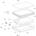
FIG. 1 is a schematic diagram of an overall structure of a battery according to an embodiment of the present invention. -
FIG. 2 is an exploded view ofFIG. 1 . -
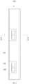
FIG. 3 is a side view ofFIG. 1 . -
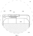
FIG. 4 is a section view taken along line A-A ofFIG. 3 . -
FIG. 5 is an enlarged view of portion B inFIG. 4 . -
FIG. 6 is a schematic diagram of an overall structure of an insulating member in a battery according to an embodiment of the present invention. -
FIG. 7 is a side view ofFIG. 6 . -
FIG. 8 is a schematic diagram of a connecting sheet in a battery according to an embodiment of the present invention. -
FIG. 9 is a side view ofFIG. 8 . - Description of reference numerals:
- 100-battery;
- 110-battery cell;
- 111-tab assembly;
- 1111-tab;
- 1112-overcurrent protection element;
- 120-housing;
- 121-notch;
- 130-insulating member;
- 131-mounting hole;
- 132-mounting groove;
- 133-sliding groove;
- 140-connecting sheet;
- 141-protruding part;
- 150-packaging housing.
- The following clearly and comprehensively describes the technical solutions in embodiments of the present invention with reference to the accompanying drawings in embodiments of the present invention. Apparently, the described embodiments are merely a part of rather than all embodiments of the present invention. All other embodiments obtained by persons of ordinary skill in the art based on embodiments of the present invention without creative labor belong to the protection scope of the present invention.
- In this application, the terms "above/on", "below", "left", "right", "front", "back", "top", "bottom", "inner", "outer", "vertical", "horizontal", "lateral", "longitudinal", etc., indicate the orientation or positional relationship based on the orientation or positional relationship shown in the drawings. These terms are used primarily to better describe the present invention and embodiments therein, and are not intended to limit that the devices, elements or components referred to must have a specific orientation, or be constructed or operated in a specific orientation.
- Moreover, some of the above terms may be used to indicate other meanings in addition to the orientation or positional relationship. For example, the term "on" may also be used to indicate a certain kind of attachment or connection relationship in some cases. For those of ordinary skill in the art, the specific meaning of the above terms in the present invention can be understood according to specific situations.
- Furthermore, the terms "mounted", "disposed", "provided," "connected", "connecting" should be understood broadly. For example, it can be a fixed connection, a detachable connection, or an integral construction; it can be a mechanical connection, or an electrical connection; it can be a direct connection, an indirect connection through an intermediary, or an internal communication between two devices, elements or components. For those of ordinary skill in the art, the specific meaning of the above terms in the present invention can be understood according to specific situations.
- Furthermore, the terms "first", "second", etc., are used primarily to distinguish between different devices, elements, or components (which may be of the same or different specific types and configurations), and are not intended to indicate or imply the relative importance or number of the devices, elements, or components referred to. "A plurality of" means two or more, unless otherwise clearly defined.
- An existing battery generally includes a battery cell, a housing, an insulating member and a pole. The battery cell is disposed inside the housing, and the housing is used for protecting the battery cell. The pole extends from the outside of the housing into the inside of the housing to be electrically connected with the tab of the battery cell, so that electrical charges of the battery cell are extended to the outside of the housing for convenient use. The insulating member is disposed between the inner side and the outer side of the housing and between the housing and the pole. However, existing pole, insulating member and the like themselves occupy large spaces, reducing a volume of the battery cell inside the housing and capacity density of the battery.
- In view of this, the present invention provides a battery. The battery includes a battery cell, a housing, an insulating member and an connecting sheet, where the housing is provided with an accommodating cavity, and the battery cell is disposed in the accommodating cavity; a side wall of the housing is provided with a notch, the insulating member is mounted at the notch, and the insulating member is provided with a mounting hole; the connecting sheet is disposed on the insulating member and is provided with a protruding part, the protruding part penetrates through the mounting hole and extends to inside of the housing, and the protruding part is electrically connected with a tab assembly of the battery cell. According to the battery provided by the present invention, the notch is formed in the side wall of the housing, and the insulating member is directly disposed at the notch. In this way, the insulating member in the present application can not only act as a part of the housing to play the role of protection and support, but also play the role of isolating the connecting sheet from the housing. The mounting hole is then formed in the insulating member, and the connecting sheet is disposed on the insulating member. The connecting sheet is provided with the protruding part, and the protruding part penetrates through the mounting hole and extends to inside of the housing. The connecting sheet is electrically connected with the tab assembly. With this arrangement, the insulating member and the connecting sheet occupy a small part of the internal space of the housing, leaving a large space for the setting of the battery cell. Therefore, capacity density of the battery is improved without changing the overall size of the battery.
-
FIG. 1 is a schematic diagram of an overall structure of a battery according to an embodiment of the present invention.FIG. 2 is an exploded view ofFIG. 1 .FIG. 3 is a side view ofFIG. 1 .FIG. 4 is a section view taken along line A-A ofFIG. 3 .FIG. 5 is an enlarged view of portion B inFIG. 4 .FIG. 6 is a schematic diagram of an overall structure of an insulating member in a battery according to an embodiment of the present invention.FIG. 7 is a side view ofFIG. 6 .FIG. 8 is a schematic diagram of a connecting sheet in a battery according to an embodiment of the present invention.FIG. 9 is a side view ofFIG. 8 . Referring toFIG. 1 to FIG. 9 , an embodiment of the present invention provides abattery 100. Thebattery 100 includes abattery cell 110, ahousing 120, an insulatingmember 130, and a connectingsheet 140. Thehousing 120 is provided with an accommodating cavity, and thebattery cell 110 is disposed in the accommodating cavity. A side wall of thehousing 120 is provided with anotch 121, the insulatingmember 130 is mounted at thenotch 121, and the insulatingmember 130 is provided with a mountinghole 131. The connectingsheet 140 is disposed on the insulatingmember 130 and is provided with a protrudingportion 141. The protrudingportion 141 penetrates through the mountinghole 131 and extends to the inside of thehousing 120, and the protrudingportion 141 is electrically connected to atab assembly 111 of thebattery cell 110. - The
battery cell 110 includes a negative electrode made of a negative electrode material, a positive electrode made of a positive electrode material, and a separator for separating the positive electrode from the negative electrode. Thebattery cell 110 may be disposed in a wound type, a laminated type, etc., which is not specifically limited in this embodiment. - It should be noted that the function of the
housing 120 is to protect thebattery cell 110 therein. Thehousing 120 may be formed by splicing two parts to facilitate installation. Thehousing 120 may be made of stainless steel, aluminum alloy, etc., which is sturdy and corrosion-resistant. Of course, thehousing 120 may also be made of other materials, which is not specifically limited in this embodiment. - The
housing 120 may be a metal housing, and the insulatingmember 130 may be made of resin, plastic, etc. The main function of the insulatingmember 130 is to isolate thehousing 120 from the connectingsheet 140 to prevent electrical contact between thehousing 120 and the connectingsheet 140. The insulatingmember 130 is disposed at thenotch 121 to replace a portion of theoriginal housing 120 at thenotch 121. The size and shape of the insulatingmember 130 may be matched with the size and shape of thenotch 121. Specifically, thenotch 121 may be rectangular in shape. - The connecting
sheet 140 is generally made of a material with good electrical conductivity, such as copper, aluminum, etc. The protrudingportion 141 on the connectingsheet 140 may be formed in advance by a stamping and forming technology, and then the connectingsheet 140 is mounted at the mountinghole 131 on the insulatingmember 130 for assembling. Alternatively, the connectingsheet 140 may cover the mountinghole 131 first, and then the protrudingportion 141 is formed on the connectingsheet 140 by stamping. With this arrangement, on one hand, a tight combination between the protrudingportion 141 and the mountinghole 131 can be ensured, and on the other hand, a length of the protrudingportion 141 may be conveniently controlled. - The mounting
hole 131 may be generally formed in a geometric center of the insulatingmember 130, so that a distance between an edge of the connectingsheet 140 and an edge of the insulatingmember 130 is relatively uniform as much as possible to ensure an insulating effect of the insulatingmember 130. - According to the
battery 100 provided by the embodiment of the present invention, thenotch 121 is formed in the side wall of thehousing 120, and the insulatingmember 130 is directly disposed at thenotch 121. In this way, the insulatingmember 130 in the embodiment of the present application can not only act as a part of thehousing 120 to play the role of protection and support, but also play the role of isolating the connectingsheet 140 from thehousing 120. The mountinghole 131 is then formed in the insulatingmember 130, and the connectingsheet 140 is disposed on the insulatingmember 130. The connectingsheet 140 is provided with theprotruding part 141, and theprotruding part 141 penetrates through the mountinghole 131 and extends to inside of thehousing 120. The connectingsheet 140 is electrically connected with thetab assembly 111. With this arrangement, the insulatingmember 130 and the connectingsheet 140 occupy a small part of the internal space of thehousing 120, leaving a large space for the setting of thebattery cell 110. Therefore, capacity density of thebattery 100 is improved without changing the overall size of thebattery 100. - In the above embodiment, a side of the insulating
member 130 away from thehousing 120 is provided with the mountinggroove 132. The mountinghole 131 may be formed at the bottom of the mountinggroove 132, the connectingsheet 140 may be disposed in the mountinggroove 132, and the connectingsheet 140 may cover the mountinghole 131. It is sufficient to make a depth of the mountinggroove 132 comparable to a thickness of the connectingsheet 140. By disposing the connectingsheet 140 in the mountinggroove 132, on the one hand, the structure of thebattery 100 may be more compact, and the overall stability of thebattery 100 may be increased; on the other hand, the connectingsheet 140 does not need to protrude from the surface of thehousing 120, and the overall size of thebattery 100 may be further reduced. - In the above embodiment, a shape of the insulating
member 130 may be matched with a shape of thenotch 121, and the insulatingmember 130 is clamped at thenotch 121. - In the above embodiment, the insulating
member 130 and thenotch 121 may be mounted together in various ways. For example, edges of both opposite sides of the insulatingmember 130 are provided with slidinggrooves 133, so that the insulatingmember 130 is clamped into thenotch 131 through the slidinggrooves 133. Specifically, as shown inFIG. 2 , thehousing 120 may be of a combined type. Thenotch 121 is formed on the side wall of one part of thehousing 120, and an opening of thenotch 121 is a place where the other part of thehousing 120 is combined. The insulatingmember 130 is clamped into thenotch 121 from the opening of thenotch 121 along the slidinggrooves 133. When the two parts of thehousing 120 are combined together, the part of thehousing 120 without the insulatingmember 130 may block the opening of thenotch 121 to prevent the insulatingmember 130 from being separated from thenotch 121. Designed in this way, the insulatingmember 130 is not only convenient to be assembled and disassembled, but also may be mounted more firmly. - As shown in
FIG. 8 , in the above embodiment, a thickness of a central region of the insulatingmember 130 is less than a thickness of edges of the insulatingmember 130 where the slidinggrooves 133 are provided. The thickness of a portion of the insulatingmember 130 where the slidinggrooves 133 are provided may be thicker than a thickness of thehousing 120, so as to ensure that the slidinggrooves 133 may be clamped into the edges of thenotch 121. It is sufficient to make the thickness of the insulatingmember 130 between the two slidinggrooves 133 comparable to the thickness of thehousing 120, so as to ensure that the space occupied by the insulatingmember 130 may be reduced as much as possible. - In practice, a welding area may be formed between a top of the connecting
sheet 140 and a groove wall of the mountinggroove 132, and the connectingsheet 140 and the insulatingmember 130 may be welded together at the welding area. - In the above embodiment, a top surface of the connecting
sheet 140 may further not exceed a top surface of the insulating member, so as to reduce the size of thebattery 100 as much as possible. - In the above embodiment, the
tab assembly 111 may include atab 1111, and the bottom of theprotruding part 141 may abut against the surface of thetab 1111. Thetab 1111 after being bent may be attached to the surface of thebattery cell 110, the protrudingpart 141 directly abuts against the surface of thetab 1111 after passing through the mountinghole 131, and then theprotruding part 141 and thetab 1111 are welded together. In this way, the structure is compact and the assembly is convenient. - In another embodiment, the
tab assembly 111 includes atab 1111 and anovercurrent protection element 1112. Theovercurrent protection element 1112 is connected between thetab 1111 and the protruding part. Theovercurrent protection element 1112 is mainly used for preventing thebattery 100 from being burnt due to an excessively high current during the charging and discharging processes of thebattery 100. Specifically, theovercurrent protection element 1112 generally includes a specific sensor, and theovercurrent protection element 1112 is normally closed. When the sensor detects that the current flowing through theovercurrent protection element 1112 is excessively high, the normally closed switch of theovercurrent protection element 1112 is open. That is, theovercurrent protection element 1112 is in a disconnected state, so that the electrical connection between thetab 1111 and the connectingsheet 140 is cut off. It should be noted that theovercurrent protection element 1112 is generally disposed at apositive tab 1111. - In the above embodiment, the
battery cell 110 may also be covered with apackaging housing 150, and thetab 1111 of thebattery cell 110 extends out of thepackaging housing 150. Thebattery cell 110 is covered by such inner and outer layers, so as to further prevent thebattery 100 from liquid leaking. - In the above embodiment, the
tab 1111 is disposed on thebattery cell 110. Thepackaging housing 150 may include a body and a sealing edge extending outwards from an edge of a side of the body. A side of thepackaging housing 150 facing thetab 1111 is provided with an opening. The sealing edge is bent in a direction close to the body; and thetab 1111 extends out of thepackaging housing 150 from the opening along the bending direction of the sealing edge. - In the above embodiment, a heat dissipation layer may further be disposed between adjacent wall surfaces of the
packaging housing 150 and thehousing 120. The heat dissipation layer may be a heat dissipation coating adhesive. The heat dissipation adhesive may be coated on the outer wall of thepackaging housing 150 to help better heat dissipation of thebattery cell 110. - In the above embodiment, the mounting
hole 131 may be formed in a circular shape, and accordingly, the protrudingportion 141 may be formed in a circular shape, and the circular protrudingportion 141 has the advantage of being easy to be machined. Of course, the shape of the mountinghole 131 may also be other shapes, such as square, rectangular, etc. The mountinghole 131 is machined into these non-circular shapes, which may ensure that the protrudingportion 141 cannot rotate relative to the mountinghole 131 after being mounted in the mountinghole 131, thereby further improving the stability of the connectingsheet 140. - The
battery 100 provided by the embodiments of the present invention includes thebattery cell 110, thehousing 120, the insulatingmember 130 and the connectingsheet 140, where thehousing 120 is provided with the accommodating cavity, and thebattery cell 110 is disposed in the accommodating cavity; the side wall of thehousing 120 is provided with thenotch 121, the insulatingmember 130 is mounted at thenotch 121, and the insulatingmember 130 is provided with the mountinghole 131; the connectingsheet 140 is disposed on the insulatingmember 130 and is provided with theprotruding part 141, the protrudingpart 141 penetrates through the mountinghole 131 and extends to inside of thehousing 120, and theprotruding part 141 is electrically connected with thetab assembly 111 of thebattery cell 110. According to thebattery 100 provided by the embodiments of the present invention, thenotch 121 is formed in the side wall of thehousing 120, and the insulatingmember 130 is directly disposed at thenotch 121. In this way, the insulatingmember 130 in the embodiments of the present application can not only act as a part of thehousing 120 to play the role of protection and support, but also play the role of isolating the connectingsheet 140 from thehousing 120. The mountinghole 131 is then formed in the insulatingmember 130, and the connectingsheet 140 is disposed on the insulatingmember 130. The connectingsheet 140 is provided with theprotruding part 141, and theprotruding part 141 penetrates through the mountinghole 131 and extends to inside of thehousing 120. The connectingsheet 140 is electrically connected with thetab assembly 111. With this arrangement, the insulatingmember 130 and the connectingsheet 140 occupy a small part of the internal space of thehousing 120, leaving a large space for the setting of thebattery cell 110. Therefore, capacity density of thebattery 100 is improved without changing the overall size of thebattery 100. - In addition, the present invention further provides an electronic device. The electronic device includes any
battery 100 in the above embodiments. Thebattery 100 includes thebattery cell 110, thehousing 120, the insulatingmember 130 and the connectingsheet 140, where thehousing 120 is provided with the accommodating cavity, and thebattery cell 110 is disposed in the accommodating cavity; the side wall of thehousing 120 is provided with thenotch 121, the insulatingmember 130 is mounted at thenotch 121, and the insulatingmember 130 is provided with the mountinghole 131; the connectingsheet 140 is disposed on the insulatingmember 131 and is provided with theprotruding part 141, the protrudingpart 141 penetrates through the mountinghole 131 and extends to inside of thehousing 120, and theprotruding part 141 is electrically connected with thetab assembly 111 of thebattery cell 110. According to thebattery 100 provided by the embodiments of the present invention, thenotch 121 is formed in the side wall of thehousing 120, and the insulatingmember 130 is directly disposed at thenotch 121. In this way, the insulatingmember 130 in the embodiments of the present application can not only act as a part of thehousing 120 to play the role of protection and support, but also play the role of isolating the connectingsheet 140 from thehousing 120. The mountinghole 131 is then formed in the insulatingmember 130, and the connectingsheet 140 is disposed on the insulatingmember 130. The connectingsheet 140 is provided with theprotruding part 141, and theprotruding part 141 penetrates through the mountinghole 131 and extends to inside of thehousing 120. The protrudingpart 141 is electrically connected with thetab assembly 111. With this arrangement, the insulatingmember 130 and the connectingsheet 140 occupy a small part of the internal space of thehousing 120, leaving a large space for the setting of thebattery cell 110. Therefore, capacity density of thebattery 100 is improved without changing the overall size of thebattery 100. Since the capacity density of thebattery 100 is improved, the limited installation space of thebattery 100 in the electronic device provided in these embodiments can accommodate thebattery 100 with a larger capacity, so that the endurance of the electronic device can be prolonged. - Finally, it should be noted that the foregoing embodiments are merely intended for describing the technical solutions of the present invention other than limiting the present invention. Although the present invention is described in detail with reference to the foregoing embodiments, those of ordinary skill in the art should understand that they may still make modifications to the technical solutions described in the foregoing embodiments or make equivalent substitutions to some or all of technical features thereof. However, these modifications and substitutions do not make the essence of the corresponding technical solutions deviate from the scope of the technical solutions of embodiments of the present invention.
Claims (20)
- A battery, comprising a battery cell, a housing, an insulating member and a connecting sheet, wherein the housing is provided with an accommodating cavity, and the battery cell is disposed in the accommodating cavity; a side wall of the housing is provided with a notch, the insulating member is mounted at the notch, and the insulating member is provided with a mounting hole; the connecting sheet is disposed on the insulating member and is provided with a protruding part, the protruding part penetrates through the mounting hole and extends to inside of the housing, and the protruding part is electrically connected with a tab assembly of the battery cell.
- The battery according to claim 1, wherein a side of the insulating member away from the housing is provided with a mounting groove, the mounting hole is located at a bottom of the mounting groove, and the connecting sheet is disposed in the mounting groove and covers the mounting hole.
- The battery according to claim 2, wherein a shape of the insulating member is matched with a shape of the notch, and the insulating member is clamped at the notch.
- The battery according to claim 3, wherein edges of both opposite sides of the insulating member are provided with sliding grooves, and the insulating member is clamped into the notch through the sliding grooves.
- The battery according to claim 4, wherein a thickness of a central region of the insulating member is less than a thickness of the edges of the insulating member where the sliding grooves are provided.
- The battery according to any one of claims 2 to 5, wherein a welding area is formed between a top of the connecting sheet and a groove wall of the mounting groove, and the connecting sheet and the insulating member are welded together at the welding area.
- The battery according to any one of claims 1 to 5, wherein a top surface of the connecting sheet does not exceed a top surface of the insulating member.
- The battery according to any one of claims 1 to 5, wherein the tab assembly comprises a tab, and a bottom of the protruding part abuts against a surface of the tab.
- The battery according to any one of claims 1 to 5, wherein the tab assembly comprises a tab and an overcurrent protection element, and the overcurrent protection element is connected between the tab and the protruding part.
- The battery according to any one of claims 1 to 5, wherein the battery cell is coated with a packaging housing, and a tab of the battery cell extends out of the packaging housing.
- The battery according to claim 10, wherein the tab is disposed on the battery cell, the packaging housing comprises a body and a sealing edge extending outwards from an edge of a side of the body, a side of the packaging housing facing the tab is provided with an opening, and the sealing edge is bent in a direction close to the body; the tab extends out of the packaging housing from the opening along a bending direction of the sealing edge.
- The battery according to claim 11, further comprising a heat dissipation layer, wherein the heat dissipation layer is disposed between adjacent wall surfaces of the packaging housing and the housing.
- The battery according to any one of claims 1 to 5, wherein the housing is a metal housing, and the insulating member is a plastic member.
- The battery according to any one of claims 1 to 5, wherein the battery cell is of a wound structure or a laminated structure.
- The battery according to any one of claims 1 to 5, wherein the notch is rectangular in shape.
- The battery according to any one of claims 1 to 5, wherein the housing is formed by a combination of two housing parts.
- The battery according to any one of claims 1 to 5, wherein the mounting hole is circular or rectangular in shape.
- The battery according to claim 17, wherein the mounting hole is provided at a geometric center of the insulating member.
- The battery according to claim 12, wherein the heat dissipation layer is a heat dissipation coating adhesive.
- An electronic device, comprising the battery according to any one of claims 1 to 19.
Applications Claiming Priority (2)
| Application Number | Priority Date | Filing Date | Title |
|---|---|---|---|
| CN202223051307.3U CN218632379U (en) | 2022-11-15 | 2022-11-15 | Battery and electronic device |
| PCT/CN2023/117838 WO2024103931A1 (en) | 2022-11-15 | 2023-09-08 | Battery and electronic device |
Publications (2)
| Publication Number | Publication Date |
|---|---|
| EP4513662A1 true EP4513662A1 (en) | 2025-02-26 |
| EP4513662A4 EP4513662A4 (en) | 2025-08-20 |
Family
ID=85446899
Family Applications (1)
| Application Number | Title | Priority Date | Filing Date |
|---|---|---|---|
| EP23890368.6A Pending EP4513662A4 (en) | 2022-11-15 | 2023-09-08 | BATTERY AND ELECTRONIC DEVICE |
Country Status (4)
| Country | Link |
|---|---|
| US (1) | US20250046972A1 (en) |
| EP (1) | EP4513662A4 (en) |
| CN (1) | CN218632379U (en) |
| WO (1) | WO2024103931A1 (en) |
Families Citing this family (1)
| Publication number | Priority date | Publication date | Assignee | Title |
|---|---|---|---|---|
| CN218632379U (en) * | 2022-11-15 | 2023-03-14 | 珠海冠宇电池股份有限公司 | Battery and electronic device |
Family Cites Families (9)
| Publication number | Priority date | Publication date | Assignee | Title |
|---|---|---|---|---|
| KR101764841B1 (en) * | 2013-02-13 | 2017-08-04 | 주식회사 엘지화학 | Electrode Assembly of Incline Structure and Battery Cell Employed with the Same |
| CN206490119U (en) * | 2017-02-28 | 2017-09-12 | 宁德时代新能源科技股份有限公司 | Battery modules |
| CN214589167U (en) * | 2021-05-14 | 2021-11-02 | 中航锂电科技有限公司 | Batteries and battery modules |
| CN114512751B (en) * | 2022-02-23 | 2024-02-09 | 上海兰钧新能源科技有限公司 | Battery core pole column assembly and welding method thereof |
| CN217426922U (en) * | 2022-03-01 | 2022-09-13 | 瑞浦兰钧能源股份有限公司 | Cap and cell assembly structure for secondary battery and secondary battery |
| CN114566694A (en) * | 2022-03-04 | 2022-05-31 | 上海兰钧新能源科技有限公司 | Battery assembly structure and battery assembly method |
| CN114614208A (en) * | 2022-03-26 | 2022-06-10 | 珠海冠宇电池股份有限公司 | Battery with a battery cell |
| CN217641722U (en) * | 2022-06-30 | 2022-10-21 | 珠海冠宇电池股份有限公司 | Battery and electronic equipment |
| CN218632379U (en) * | 2022-11-15 | 2023-03-14 | 珠海冠宇电池股份有限公司 | Battery and electronic device |
-
2022
- 2022-11-15 CN CN202223051307.3U patent/CN218632379U/en active Active
-
2023
- 2023-09-08 EP EP23890368.6A patent/EP4513662A4/en active Pending
- 2023-09-08 WO PCT/CN2023/117838 patent/WO2024103931A1/en not_active Ceased
-
2024
- 2024-10-24 US US18/925,559 patent/US20250046972A1/en active Pending
Also Published As
| Publication number | Publication date |
|---|---|
| CN218632379U (en) | 2023-03-14 |
| EP4513662A4 (en) | 2025-08-20 |
| WO2024103931A1 (en) | 2024-05-23 |
| US20250046972A1 (en) | 2025-02-06 |
Similar Documents
| Publication | Publication Date | Title |
|---|---|---|
| KR100870349B1 (en) | Connection terminal of protective circuit board and secondary battery using same | |
| EP2317587B1 (en) | Rechargeable battery | |
| EP2838135B1 (en) | Rechargeable battery pack | |
| EP2073295B1 (en) | Protective circuit board for a battery | |
| EP1906469A1 (en) | Battery Pack | |
| EP2955768B1 (en) | Battery cell including stepped structure | |
| US7662511B2 (en) | Secondary battery having an enlarged electrolytic solution inlet | |
| US8530079B2 (en) | Rechargeable battery | |
| EP4250439B1 (en) | Battery | |
| CN110880563A (en) | Battery case assembly and battery having the same | |
| EP3799182B1 (en) | Secondary battery, battery pack and electric device | |
| EP4250465A2 (en) | Battery | |
| CN114614214A (en) | Battery with a battery cell | |
| EP4510317A1 (en) | Battery and electronic device | |
| US20250046972A1 (en) | Battery and electronic device | |
| JP2013161790A (en) | Secondary battery | |
| CN114361385B (en) | Battery and electronic equipment | |
| CN209786057U (en) | A connecting member and secondary battery | |
| JP7359849B2 (en) | Batteries and electrical equipment equipped with them | |
| CN118040003A (en) | Battery core and electric equipment | |
| US20250070406A1 (en) | Battery and electronic device | |
| CN217507539U (en) | Battery and battery device | |
| EP2600432A1 (en) | Lithium ion battery | |
| CN113921966B (en) | Battery and electronic device | |
| CN216120417U (en) | Lithium ion battery |
Legal Events
| Date | Code | Title | Description |
|---|---|---|---|
| STAA | Information on the status of an ep patent application or granted ep patent |
Free format text: STATUS: THE INTERNATIONAL PUBLICATION HAS BEEN MADE |
|
| PUAI | Public reference made under article 153(3) epc to a published international application that has entered the european phase |
Free format text: ORIGINAL CODE: 0009012 |
|
| STAA | Information on the status of an ep patent application or granted ep patent |
Free format text: STATUS: REQUEST FOR EXAMINATION WAS MADE |
|
| 17P | Request for examination filed |
Effective date: 20241122 |
|
| AK | Designated contracting states |
Kind code of ref document: A1 Designated state(s): AL AT BE BG CH CY CZ DE DK EE ES FI FR GB GR HR HU IE IS IT LI LT LU LV MC ME MK MT NL NO PL PT RO RS SE SI SK SM TR |
|
| A4 | Supplementary search report drawn up and despatched |
Effective date: 20250722 |
|
| RIC1 | Information provided on ipc code assigned before grant |
Ipc: H01M 50/572 20210101AFI20250716BHEP Ipc: H01M 50/531 20210101ALI20250716BHEP Ipc: H01M 50/102 20210101ALI20250716BHEP Ipc: H01M 50/116 20210101ALI20250716BHEP Ipc: H01M 50/14 20210101ALI20250716BHEP Ipc: H01M 10/04 20060101ALI20250716BHEP Ipc: H01M 50/176 20210101ALI20250716BHEP |
|
| STAA | Information on the status of an ep patent application or granted ep patent |
Free format text: STATUS: EXAMINATION IS IN PROGRESS |
|
| 17Q | First examination report despatched |
Effective date: 20251209 |
|
| DAV | Request for validation of the european patent (deleted) | ||
| DAX | Request for extension of the european patent (deleted) |