EP4513648A2 - Battery pack with increased lifespan of battery cell and device including the same - Google Patents
Battery pack with increased lifespan of battery cell and device including the same Download PDFInfo
- Publication number
- EP4513648A2 EP4513648A2 EP25150889.1A EP25150889A EP4513648A2 EP 4513648 A2 EP4513648 A2 EP 4513648A2 EP 25150889 A EP25150889 A EP 25150889A EP 4513648 A2 EP4513648 A2 EP 4513648A2
- Authority
- EP
- European Patent Office
- Prior art keywords
- battery
- support plate
- plate
- pack
- battery cell
- Prior art date
- Legal status (The legal status is an assumption and is not a legal conclusion. Google has not performed a legal analysis and makes no representation as to the accuracy of the status listed.)
- Granted
Links
Images






Classifications
-
- H—ELECTRICITY
- H01—ELECTRIC ELEMENTS
- H01M—PROCESSES OR MEANS, e.g. BATTERIES, FOR THE DIRECT CONVERSION OF CHEMICAL ENERGY INTO ELECTRICAL ENERGY
- H01M50/00—Constructional details or processes of manufacture of the non-active parts of electrochemical cells other than fuel cells, e.g. hybrid cells
- H01M50/20—Mountings; Secondary casings or frames; Racks, modules or packs; Suspension devices; Shock absorbers; Transport or carrying devices; Holders
- H01M50/204—Racks, modules or packs for multiple batteries or multiple cells
-
- H—ELECTRICITY
- H01—ELECTRIC ELEMENTS
- H01M—PROCESSES OR MEANS, e.g. BATTERIES, FOR THE DIRECT CONVERSION OF CHEMICAL ENERGY INTO ELECTRICAL ENERGY
- H01M50/00—Constructional details or processes of manufacture of the non-active parts of electrochemical cells other than fuel cells, e.g. hybrid cells
- H01M50/20—Mountings; Secondary casings or frames; Racks, modules or packs; Suspension devices; Shock absorbers; Transport or carrying devices; Holders
-
- H—ELECTRICITY
- H01—ELECTRIC ELEMENTS
- H01M—PROCESSES OR MEANS, e.g. BATTERIES, FOR THE DIRECT CONVERSION OF CHEMICAL ENERGY INTO ELECTRICAL ENERGY
- H01M10/00—Secondary cells; Manufacture thereof
- H01M10/04—Construction or manufacture in general
- H01M10/0481—Compression means other than compression means for stacks of electrodes and separators
-
- H—ELECTRICITY
- H01—ELECTRIC ELEMENTS
- H01M—PROCESSES OR MEANS, e.g. BATTERIES, FOR THE DIRECT CONVERSION OF CHEMICAL ENERGY INTO ELECTRICAL ENERGY
- H01M10/00—Secondary cells; Manufacture thereof
- H01M10/60—Heating or cooling; Temperature control
- H01M10/64—Heating or cooling; Temperature control characterised by the shape of the cells
- H01M10/647—Prismatic or flat cells, e.g. pouch cells
-
- H—ELECTRICITY
- H01—ELECTRIC ELEMENTS
- H01M—PROCESSES OR MEANS, e.g. BATTERIES, FOR THE DIRECT CONVERSION OF CHEMICAL ENERGY INTO ELECTRICAL ENERGY
- H01M10/00—Secondary cells; Manufacture thereof
- H01M10/60—Heating or cooling; Temperature control
- H01M10/65—Means for temperature control structurally associated with the cells
- H01M10/655—Solid structures for heat exchange or heat conduction
- H01M10/6551—Surfaces specially adapted for heat dissipation or radiation, e.g. fins or coatings
-
- H—ELECTRICITY
- H01—ELECTRIC ELEMENTS
- H01M—PROCESSES OR MEANS, e.g. BATTERIES, FOR THE DIRECT CONVERSION OF CHEMICAL ENERGY INTO ELECTRICAL ENERGY
- H01M50/00—Constructional details or processes of manufacture of the non-active parts of electrochemical cells other than fuel cells, e.g. hybrid cells
- H01M50/20—Mountings; Secondary casings or frames; Racks, modules or packs; Suspension devices; Shock absorbers; Transport or carrying devices; Holders
- H01M50/204—Racks, modules or packs for multiple batteries or multiple cells
- H01M50/207—Racks, modules or packs for multiple batteries or multiple cells characterised by their shape
- H01M50/211—Racks, modules or packs for multiple batteries or multiple cells characterised by their shape adapted for pouch cells
-
- H—ELECTRICITY
- H01—ELECTRIC ELEMENTS
- H01M—PROCESSES OR MEANS, e.g. BATTERIES, FOR THE DIRECT CONVERSION OF CHEMICAL ENERGY INTO ELECTRICAL ENERGY
- H01M50/00—Constructional details or processes of manufacture of the non-active parts of electrochemical cells other than fuel cells, e.g. hybrid cells
- H01M50/20—Mountings; Secondary casings or frames; Racks, modules or packs; Suspension devices; Shock absorbers; Transport or carrying devices; Holders
- H01M50/218—Mountings; Secondary casings or frames; Racks, modules or packs; Suspension devices; Shock absorbers; Transport or carrying devices; Holders characterised by the material
- H01M50/22—Mountings; Secondary casings or frames; Racks, modules or packs; Suspension devices; Shock absorbers; Transport or carrying devices; Holders characterised by the material of the casings or racks
- H01M50/222—Inorganic material
- H01M50/224—Metals
-
- H—ELECTRICITY
- H01—ELECTRIC ELEMENTS
- H01M—PROCESSES OR MEANS, e.g. BATTERIES, FOR THE DIRECT CONVERSION OF CHEMICAL ENERGY INTO ELECTRICAL ENERGY
- H01M50/00—Constructional details or processes of manufacture of the non-active parts of electrochemical cells other than fuel cells, e.g. hybrid cells
- H01M50/20—Mountings; Secondary casings or frames; Racks, modules or packs; Suspension devices; Shock absorbers; Transport or carrying devices; Holders
- H01M50/233—Mountings; Secondary casings or frames; Racks, modules or packs; Suspension devices; Shock absorbers; Transport or carrying devices; Holders characterised by physical properties of casings or racks, e.g. dimensions
- H01M50/24—Mountings; Secondary casings or frames; Racks, modules or packs; Suspension devices; Shock absorbers; Transport or carrying devices; Holders characterised by physical properties of casings or racks, e.g. dimensions adapted for protecting batteries from their environment, e.g. from corrosion
-
- H—ELECTRICITY
- H01—ELECTRIC ELEMENTS
- H01M—PROCESSES OR MEANS, e.g. BATTERIES, FOR THE DIRECT CONVERSION OF CHEMICAL ENERGY INTO ELECTRICAL ENERGY
- H01M50/00—Constructional details or processes of manufacture of the non-active parts of electrochemical cells other than fuel cells, e.g. hybrid cells
- H01M50/20—Mountings; Secondary casings or frames; Racks, modules or packs; Suspension devices; Shock absorbers; Transport or carrying devices; Holders
- H01M50/262—Mountings; Secondary casings or frames; Racks, modules or packs; Suspension devices; Shock absorbers; Transport or carrying devices; Holders with fastening means, e.g. locks
- H01M50/264—Mountings; Secondary casings or frames; Racks, modules or packs; Suspension devices; Shock absorbers; Transport or carrying devices; Holders with fastening means, e.g. locks for cells or batteries, e.g. straps, tie rods or peripheral frames
-
- H—ELECTRICITY
- H01—ELECTRIC ELEMENTS
- H01M—PROCESSES OR MEANS, e.g. BATTERIES, FOR THE DIRECT CONVERSION OF CHEMICAL ENERGY INTO ELECTRICAL ENERGY
- H01M50/00—Constructional details or processes of manufacture of the non-active parts of electrochemical cells other than fuel cells, e.g. hybrid cells
- H01M50/20—Mountings; Secondary casings or frames; Racks, modules or packs; Suspension devices; Shock absorbers; Transport or carrying devices; Holders
- H01M50/289—Mountings; Secondary casings or frames; Racks, modules or packs; Suspension devices; Shock absorbers; Transport or carrying devices; Holders characterised by spacing elements or positioning means within frames, racks or packs
- H01M50/293—Mountings; Secondary casings or frames; Racks, modules or packs; Suspension devices; Shock absorbers; Transport or carrying devices; Holders characterised by spacing elements or positioning means within frames, racks or packs characterised by the material
-
- H—ELECTRICITY
- H01—ELECTRIC ELEMENTS
- H01M—PROCESSES OR MEANS, e.g. BATTERIES, FOR THE DIRECT CONVERSION OF CHEMICAL ENERGY INTO ELECTRICAL ENERGY
- H01M50/00—Constructional details or processes of manufacture of the non-active parts of electrochemical cells other than fuel cells, e.g. hybrid cells
- H01M50/50—Current conducting connections for cells or batteries
- H01M50/502—Interconnectors for connecting terminals of adjacent batteries; Interconnectors for connecting cells outside a battery casing
-
- H—ELECTRICITY
- H01—ELECTRIC ELEMENTS
- H01M—PROCESSES OR MEANS, e.g. BATTERIES, FOR THE DIRECT CONVERSION OF CHEMICAL ENERGY INTO ELECTRICAL ENERGY
- H01M50/00—Constructional details or processes of manufacture of the non-active parts of electrochemical cells other than fuel cells, e.g. hybrid cells
- H01M50/50—Current conducting connections for cells or batteries
- H01M50/502—Interconnectors for connecting terminals of adjacent batteries; Interconnectors for connecting cells outside a battery casing
- H01M50/507—Interconnectors for connecting terminals of adjacent batteries; Interconnectors for connecting cells outside a battery casing comprising an arrangement of two or more busbars within a container structure, e.g. busbar modules
-
- H—ELECTRICITY
- H01—ELECTRIC ELEMENTS
- H01M—PROCESSES OR MEANS, e.g. BATTERIES, FOR THE DIRECT CONVERSION OF CHEMICAL ENERGY INTO ELECTRICAL ENERGY
- H01M2220/00—Batteries for particular applications
- H01M2220/20—Batteries in motive systems, e.g. vehicle, ship, plane
-
- H—ELECTRICITY
- H01—ELECTRIC ELEMENTS
- H01M—PROCESSES OR MEANS, e.g. BATTERIES, FOR THE DIRECT CONVERSION OF CHEMICAL ENERGY INTO ELECTRICAL ENERGY
- H01M50/00—Constructional details or processes of manufacture of the non-active parts of electrochemical cells other than fuel cells, e.g. hybrid cells
- H01M50/20—Mountings; Secondary casings or frames; Racks, modules or packs; Suspension devices; Shock absorbers; Transport or carrying devices; Holders
- H01M50/233—Mountings; Secondary casings or frames; Racks, modules or packs; Suspension devices; Shock absorbers; Transport or carrying devices; Holders characterised by physical properties of casings or racks, e.g. dimensions
- H01M50/242—Mountings; Secondary casings or frames; Racks, modules or packs; Suspension devices; Shock absorbers; Transport or carrying devices; Holders characterised by physical properties of casings or racks, e.g. dimensions adapted for protecting batteries against vibrations, collision impact or swelling
-
- Y—GENERAL TAGGING OF NEW TECHNOLOGICAL DEVELOPMENTS; GENERAL TAGGING OF CROSS-SECTIONAL TECHNOLOGIES SPANNING OVER SEVERAL SECTIONS OF THE IPC; TECHNICAL SUBJECTS COVERED BY FORMER USPC CROSS-REFERENCE ART COLLECTIONS [XRACs] AND DIGESTS
- Y02—TECHNOLOGIES OR APPLICATIONS FOR MITIGATION OR ADAPTATION AGAINST CLIMATE CHANGE
- Y02E—REDUCTION OF GREENHOUSE GAS [GHG] EMISSIONS, RELATED TO ENERGY GENERATION, TRANSMISSION OR DISTRIBUTION
- Y02E60/00—Enabling technologies; Technologies with a potential or indirect contribution to GHG emissions mitigation
- Y02E60/10—Energy storage using batteries
Definitions
- the present invention relates to a battery pack and a device including the same, and more particularly to a battery pack with increased lifespan of a battery cell configured to have a structure in which pressure applied to the battery cell is maintained at an appropriate level, whereby lifespan of the battery cell is extended, and the battery cell is in surface contact with a heat sink, whereby rapid heat dissipation is achieved, and a device including the same.
- the secondary batteries which are being capable of being charged and discharged, are intimately used in daily life.
- the secondary batteries are used in mobile devices, electric vehicles, and hybrid electric vehicles.
- a battery cell swells during repeated charging and discharging thereof, whereby the overall volume of the battery cell is increased.
- electrical contact between an electrode and an active material must be improved. To this end, it is necessary to constantly apply a predetermined level of pressing force to the battery cell.
- FIG. 1 is a perspective view showing the structure of a conventional battery module.
- the conventional battery module includes a plurality of single cells 10 disposed perpendicular to a heat sink 20, a case 30 configured to wrap the plurality of single cells 10 in order to protect the plurality of single cells, pressing plates 40 located at opposite sides of the plurality of single cells 10 vertically disposed, and pressure adjustment members 50 located between the pressing plates 40 and the case 30.
- a second busbar assembly (320) may be located between the lower support plate (220) and the lower cover plate (620).
- FIG. 2 is a perspective view of a battery pack according to a preferred embodiment of the present invention
- FIG. 3 is an exploded perspective view of the battery pack shown in FIG. 2
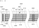
- FIG. 4 is a sectional view taken along line A-A' of FIG. 2 .
- the battery pack 2000 includes a plurality of horizontally stacked battery modules 1000, a pressing plate 2100 located at the upper surface and the lower surface of the plurality of stacked battery modules 1000, an elastic member 2200, a pack case 2300, a plurality of fastening members 2400 configured to fix the battery modules 1000, and a distance retention portion 2500.
- the pressing plate 2100 includes an upper pressing plate 2110 located on the upper surface of the stacked battery modules 1000 in tight contact therewith, a lower pressing plate 2120 located on the lower surface of the stacked battery modules 1000 in tight contact therewith, and a plurality of side plates 2130 located at opposite side surfaces of the battery modules 1000 in a state of being spaced apart therefrom by a predetermined distance.
- the elastic member 2200 includes a first elastic member 2210, a second elastic member 2220, and a third elastic member 2230.
- the first elastic member 2210 and the second elastic member 2220 provide tensile force between the upper pressing plate 2110 and the lower pressing plate 2120, whereas the third elastic member 2230 is located between the upper pressing plate 2110 and an upper pack cover 2310 to provide pressing force.
- the third elastic member 2230 it is preferable for the third elastic member 2230 to be provided in plural in a state of being spaced apart from each other by a predetermined distance.
- the third elastic member inhibits bending of the pressing plate that may be caused by a swelling deviation between the battery cells, whereby it is possible to minimize a deviation in pressing force.
- the pack case 2300 includes an upper pack cover 2310 located at the upper surface of the upper pressing plate 2110, a lower pack cover 2320 located at the lower surface of the lower pressing plate 2120, and side pack covers 2330 located parallel to the side plates 2130.
- the fastening members 2400 are configured to fix the plurality of battery modules 1000, which are stacked in a vertical direction, using predetermined force.
- each of the fastening members may be a bolt having a screw thread formed at one end thereof, and a nut may be fastened to the other side of the fastening member in order to fix the battery modules 1000.
- the nuts are somewhat loosely fastened to the fastening members in consideration of expansion of the battery modules upon swelling.
- the distance retention portion 2500 may be further provided between the upper pressing plate 2110 and the upper pack cover 2310 at the middle thereof in order to supplement tensile force by the first elastic member 2210 and pressing force by the third elastic member 2230.
- the distance retention portion may be a quadrangular pillar made of metal.
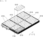
- FIG. 5 is an exploded perspective view of a battery module according to a preferred embodiment of the present invention.
- the battery module 1000 includes a heat sink 100, a support plate 200, a busbar assembly 300, a support frame 400, battery cells 500, and a cover plate 600.
- the heat sink 100 is a flat plate that is provided with a flow channel defined therein and has a predetermined area.
- a plurality of protuberances 110 is formed on the upper surface and the lower surface of the heat sink 100 so as to protrude therefrom in a state of being spaced apart from each other by a predetermined distance.
- the protuberances 110 will be described below in detail.
- the support plate 200 includes an upper support plate 210 and a lower support plate 220 located at opposite surfaces of the heat sink 100, more specifically the upper surface of the heat sink 100 and the lower surface of the heat sink 100, respectively.
- the busbar assembly 300 configured to electrically connect the battery cells 500 to each other includes a first busbar assembly 310 and a second busbar assembly 320.
- the first busbar assembly 310 is located at the upper surface of the upper support plate 210, and the second busbar assembly 320 is disposed at the lower surface of the lower support plate 220.
- the second busbar assemblies 320 are symmetrical with the first busbar assemblies 310, and therefore an additional description thereof will be omitted.
- the support frame 400 includes first support frames 410 and second support frames 420.
- the first support frames 410 are located between the upper support plate 210 and an upper cover plate 610
- the second support frames 420 are located between the lower support plate 220 and the lower cover plate 620.
- the first support frames and the second support frames will be described below in more detail.
Landscapes
- Chemical & Material Sciences (AREA)
- Chemical Kinetics & Catalysis (AREA)
- Electrochemistry (AREA)
- General Chemical & Material Sciences (AREA)
- Engineering & Computer Science (AREA)
- Manufacturing & Machinery (AREA)
- Inorganic Chemistry (AREA)
- Battery Mounting, Suspending (AREA)
- Secondary Cells (AREA)
- Connection Of Batteries Or Terminals (AREA)
Abstract
Description
- This application claims the benefit of priority to
Korean Patent Application No. 2020-0121927 filed on September 22, 2020 - The present invention relates to a battery pack and a device including the same, and more particularly to a battery pack with increased lifespan of a battery cell configured to have a structure in which pressure applied to the battery cell is maintained at an appropriate level, whereby lifespan of the battery cell is extended, and the battery cell is in surface contact with a heat sink, whereby rapid heat dissipation is achieved, and a device including the same.
- With recent development of alternative energies due to air pollution and energy depletion caused as the result of use of fossil fuels, demand for secondary batteries capable of storing electrical energy that is produced has increased. The secondary batteries, which are being capable of being charged and discharged, are intimately used in daily life. For example, the secondary batteries are used in mobile devices, electric vehicles, and hybrid electric vehicles.
- Required capacities of secondary batteries used as energy sources of various kinds of electronic devices inevitably used in modern society have been increased due to an increase in usage of mobile devices, increasing complexity of the mobile devices, and development of electric vehicles. In order to satisfy demand of users, a plurality of battery cells is disposed in a small-sized device, whereas a battery module including a plurality of battery cells electrically connected to each other or a battery pack including a plurality of battery modules is used in a vehicle.
- Meanwhile, a battery cell swells during repeated charging and discharging thereof, whereby the overall volume of the battery cell is increased. In order to increase lifespan of the battery cell, however, electrical contact between an electrode and an active material must be improved. To this end, it is necessary to constantly apply a predetermined level of pressing force to the battery cell.
-
FIG. 1 is a perspective view showing the structure of a conventional battery module. As shown inFIG. 1 , the conventional battery module includes a plurality ofsingle cells 10 disposed perpendicular to aheat sink 20, acase 30 configured to wrap the plurality ofsingle cells 10 in order to protect the plurality of single cells, pressingplates 40 located at opposite sides of the plurality ofsingle cells 10 vertically disposed, andpressure adjustment members 50 located between thepressing plates 40 and thecase 30. - The conventional battery module is configured to have a structure in which the
pressure adjustment members 50, which are elastic members, are located between thecase 30 and thepressing plates 40 in order to press the opposite sides of thesingle cells 10, whereby an increase in volume of the single cells at the time of swelling is inhibited. - In the conventional battery module, however, only pressing is performed and no pressure adjustment function is provided. As a result, it is not possible to increase lifespan of the battery cells.
-
JP 2019-125455 A - The present invention has been made in view of the above problems.
- It is an object of the present invention to provide a battery pack capable of inhibiting occurrence of a secondary problem due to heat generation by efficiently removing heat generated from a battery cell and a device including the same.
- It is a further object of the present invention to provide a battery pack capable of reducing battery cell cooling deviation by increasing adhesion force and a device including the same.
- In order to accomplish the above objects, a battery pack according to the present invention includes a plurality of battery modules (1000) stacked in a vertical direction in a horizontal state; a pressing plate (2100) including an upper pressing plate (2110) and a lower pressing plate (2120) located outside the plurality of battery modules (1000); a first (2210) and a second elastic member (2220) configured to connect the upper pressing plate (2110) and the lower pressing plate (2120) to each other with a tensile force; and a pack case (2300) configured to wrap the pressing plate (2100), wherein the pack case (2300) includes an upper pack cover (2310) and a lower pack cover (2320), and a third elastic member (2230) is provided between the upper pack cover (2310) and the upper pressing plate (2110), wherein each of the battery modules (1000) includes a heat sink (100) having a predetermined area, the heat sink being horizontally located; a support plate (200) including an upper support plate (210) and a lower support plate (220) located respectively at the upper surface and the lower surface of the heat sink (100); a battery cell (500) including a first battery cell (510) disposed in tight contact with the upper support plate (210) and a second battery cell (520) disposed in tight contact with the lower support plate (220); and a cover plate (600) including an upper cover plate (610) located above the first battery cell (510) and a lower cover plate (620) located under the second battery cell (520).
- Also, in the battery pack according to the present invention, the heat sink (100) may be provided on the upper surface thereof with a protuberance (110) protruding by a predetermined height, and the upper support plate (210) may be provided with a first opening (211) configured to receive the protuberance (110).
- Also, in the battery pack according to the present invention, the first battery cell (510) may be located at the upper surface of the protuberance (110).
- Also, in the battery pack according to the present invention, the heat sink (100) may be provided on the lower surface thereof with a protuberance (110) protruding by a predetermined height, and the lower support plate (220) may be provided with a second opening (221) configured to receive the protuberance (110).
- Also, in the battery pack according to the present invention, the second battery cell (520) may be located at the lower surface of the protuberance (110).
- Also, in the battery pack according to the present invention, first support frames (410) may be located between the upper support plate (210) and the upper cover plate (610) so as to extend along opposite edges and the middle thereof while having a predetermined height and width.
- Also, in the battery pack according to the present invention, second support frames (420) may be located between the lower support plate (220) and the lower cover plate (620) so as to extend along opposite edges and the middle thereof while having a predetermined height and width.
- Also, in the battery pack according to the present invention, the first support frame (410) and the second support frame (420) extending along the middle of each of the upper support plate and the upper cover plate or the middle of each of the lower support plate and the lower cover plate may be provided respectively with a first through-hole (411) and a second through-hole (421) configured to allow a first elastic member (2210) to be inserted therethrough.
- Also, in the battery pack according to the present invention, a first busbar assembly (310) may be located between the upper support plate (210) and the upper cover plate (610), and the first busbar assembly (310) may include a first busbar frame (311) having a first receiving recess (311(a)) formed therein and a busbar (312) seated in the first receiving recess (311(a)), the busbar being configured to have a concave-convex structure that is bent at a predetermined angle a plurality of times.
- Also, in the battery pack according to the present invention, a second busbar assembly (320) may be located between the lower support plate (220) and the lower cover plate (620).
- In addition, the present invention provides a device including the battery pack.
- The battery pack with increased lifespan of the battery cell according to the present invention and the device including the same have a merit in that relatively wide side surfaces of the battery cells and a heat sink are in tight contact with each other in a state of being located in a horizontal direction, whereby cooling performance of the battery cells is improved due to an increase in heat transfer area.
- Furthermore, the battery pack with increased lifespan of the battery cell according to the present invention and the device including the same have an advantage in that the battery cells, the heat sink, a support plate, etc. are fastened to each other via a plurality of support frames and fastening members, whereby it is possible to maintain uniform adhesion force between the battery cells and the heat sink while maximizing space utilization.
-
-
FIG. 1 is a perspective view of a conventional battery module. -
FIG. 2 is a perspective view of a battery pack according to a preferred embodiment of the present invention. -
FIG. 3 is an exploded perspective view of the battery pack shown inFIG. 2 . -
FIG. 4 is a sectional view taken along line A-A' ofFIG. 2 . -
FIG. 5 is an exploded perspective view of a battery module according to a preferred embodiment of the present invention. -
FIG. 6 is a perspective view illustrating a coupling structure between a heat sink and a support plate in the battery module according to the preferred embodiment of the present invention. -
FIG. 7 is a perspective view illustrating a battery cell mounting structure in the battery module according to the preferred embodiment of the present invention. -
FIG. 8 is a perspective view illustrating a support frame disposition structure in the battery module according to the preferred embodiment of the present invention. -
FIG. 9 is a perspective view illustrating a coupling structure between battery cells and busbars in the battery module according to the preferred embodiment of the present invention. - Now, preferred embodiments of the present invention will be described in detail with reference to the accompanying drawings such that the preferred embodiments of the present invention can be easily implemented by a person having ordinary skill in the art to which the present invention pertains. In describing the principle of operation of the preferred embodiments of the present invention in detail, however, a detailed description of known functions and configurations incorporated herein will be omitted when the same may obscure the subject matter of the present invention.
- In addition, the same reference numbers will be used throughout the drawings to refer to parts that perform similar functions or operations. In the case in which one part is said to be connected to another part in the entire specification, not only may the one part be directly connected to the other part, but also, the one part may be indirectly connected to the other part via a further part. In addition, that a certain element is included does not mean that other elements are excluded, but means that such elements may be further included unless mentioned otherwise.
- Hereinafter, a battery pack with increased lifespan of a battery cell according to the present invention will be described with reference to the accompanying drawings.
-
FIG. 2 is a perspective view of a battery pack according to a preferred embodiment of the present invention,FIG. 3 is an exploded perspective view of the battery pack shown inFIG. 2 , andFIG. 4 is a sectional view taken along line A-A' ofFIG. 2 . - As shown in
FIGS. 2 to 4 , thebattery pack 2000 according to the present invention includes a plurality of horizontally stackedbattery modules 1000, apressing plate 2100 located at the upper surface and the lower surface of the plurality of stackedbattery modules 1000, anelastic member 2200, apack case 2300, a plurality of fasteningmembers 2400 configured to fix thebattery modules 1000, and adistance retention portion 2500. - First, the
pressing plate 2100 includes an upperpressing plate 2110 located on the upper surface of the stackedbattery modules 1000 in tight contact therewith, a lowerpressing plate 2120 located on the lower surface of the stackedbattery modules 1000 in tight contact therewith, and a plurality ofside plates 2130 located at opposite side surfaces of thebattery modules 1000 in a state of being spaced apart therefrom by a predetermined distance. - The
elastic member 2200 includes a firstelastic member 2210, a secondelastic member 2220, and a thirdelastic member 2230. One side of each of a plurality of firstelastic members 2210, which are inserted perpendicularly through middle parts of thebattery modules 1000, is connected to the upperpressing plate 2110, and the other side of each of the first elastic members is connected to the lowerpressing plate 2120. Since middle parts of the upperpressing plate 2110 and the lowerpressing plate 2120 are pulled, therefore, it is possible to constantly pressbattery cells 500 located at the middle parts of thebattery modules 1000 within a predetermined range irrespective of swelling. - The second
elastic member 2220, which connects the upperpressing plate 2110 and the lowerpressing plate 2120, specifically the edge of the upperpressing plate 2110 and the edge of the lowerpressing plate 2120, to each other, constantly pressesbattery cells 500 located at edges of thebattery modules 1000 within a predetermined range. - The first
elastic member 2210 and the secondelastic member 2220 provide tensile force between the upperpressing plate 2110 and the lowerpressing plate 2120, whereas the thirdelastic member 2230 is located between the upperpressing plate 2110 and anupper pack cover 2310 to provide pressing force. In particular, it is preferable for the thirdelastic member 2230 to be provided in plural in a state of being spaced apart from each other by a predetermined distance. The third elastic member inhibits bending of the pressing plate that may be caused by a swelling deviation between the battery cells, whereby it is possible to minimize a deviation in pressing force. - Here, each of the first
elastic member 2210, the secondelastic member 2220, and the thirdelastic member 2230 may be a coil. However, the present invention is not limited thereto. - The
pack case 2300 includes anupper pack cover 2310 located at the upper surface of the upperpressing plate 2110, alower pack cover 2320 located at the lower surface of the lower pressingplate 2120, and side pack covers 2330 located parallel to theside plates 2130. - The
fastening members 2400 are configured to fix the plurality ofbattery modules 1000, which are stacked in a vertical direction, using predetermined force. As an example, each of the fastening members may be a bolt having a screw thread formed at one end thereof, and a nut may be fastened to the other side of the fastening member in order to fix thebattery modules 1000. - Of course, it is preferable for the nuts to be somewhat loosely fastened to the fastening members in consideration of expansion of the battery modules upon swelling.
- Meanwhile, the
distance retention portion 2500 may be further provided between the upperpressing plate 2110 and theupper pack cover 2310 at the middle thereof in order to supplement tensile force by the firstelastic member 2210 and pressing force by the thirdelastic member 2230. The distance retention portion may be a quadrangular pillar made of metal. -
FIG. 5 is an exploded perspective view of a battery module according to a preferred embodiment of the present invention. As shown inFIG. 5 , thebattery module 1000 includes aheat sink 100, asupport plate 200, abusbar assembly 300, asupport frame 400,battery cells 500, and acover plate 600. - First, the
heat sink 100 is a flat plate that is provided with a flow channel defined therein and has a predetermined area. A plurality ofprotuberances 110 is formed on the upper surface and the lower surface of theheat sink 100 so as to protrude therefrom in a state of being spaced apart from each other by a predetermined distance. Theprotuberances 110 will be described below in detail. - The
support plate 200 includes anupper support plate 210 and alower support plate 220 located at opposite surfaces of theheat sink 100, more specifically the upper surface of theheat sink 100 and the lower surface of theheat sink 100, respectively. - The
busbar assembly 300 configured to electrically connect thebattery cells 500 to each other includes afirst busbar assembly 310 and asecond busbar assembly 320. Thefirst busbar assembly 310 is located at the upper surface of theupper support plate 210, and thesecond busbar assembly 320 is disposed at the lower surface of thelower support plate 220. - A total of six
first busbar assemblies 310, one of which is located in the vicinity of each of opposite edges of theupper support plate 210 and four of which are located between the two first busbar assemblies located in the vicinity of the opposite edges of the upper support plate in a state of being spaced apart from each other by a predetermined distance in a longitudinal direction (an X-axis direction), are shown in the figure, which, however, is merely an example. The number or position of first busbar assemblies may be changed as long as the first busbar assemblies can be brought into tight contact with theupper support plate 210. - The
second busbar assemblies 320 are symmetrical with thefirst busbar assemblies 310, and therefore an additional description thereof will be omitted. - Next, the
support frame 400 includes first support frames 410 and second support frames 420. The first support frames 410 are located between theupper support plate 210 and anupper cover plate 610, and the second support frames 420 are located between thelower support plate 220 and thelower cover plate 620. The first support frames and the second support frames will be described below in more detail. - The
battery cells 500 include a plurality offirst battery cells 510 and a plurality ofsecond battery cells 520 located parallel to theheat sink 100. Specifically, thefirst battery cells 510 are located between theupper support plate 210 and theupper cover plate 610, and thesecond battery cells 520 are located between thelower support plate 220 and thelower cover plate 620. - The
first battery cells 510 and thesecond battery cells 520 may be battery cells having the same construction. For example, each battery cell may include a cell case, in which an electrode assembly (not shown) is received, and a pair of electrode leads. - Here, the electrode assembly may be a jelly-roll type assembly, which is configured to have a structure in which a long sheet type positive electrode and a long sheet type negative electrode are wound in the state in which a separator is interposed therebetween, a stacked type assembly which is configured to have a structure in which a rectangular positive electrode and a rectangular negative electrode are stacked in the state in which a separator is interposed therebetween, a stacked and folded type assembly, which is configured to have a structure in which unit cells are wound using a long separation film, or a laminated and stacked type assembly, which is configured to have a structure in which battery cells are stacked in the state in which a separator is interposed therebetween and are then attached to each other. However, the present invention is not limited thereto. It is preferable for the electrode assembly according to the present invention to be a stacked and folded type assembly or a laminated and stacked type assembly, which has lowest physical stress when a curved module is formed.
- The electrode assembly is received in the cell case. The cell case is generally configured to have a laminate sheet structure including an inner layer, a metal layer, and an outer layer. The inner layer is disposed in direct contact with the electrode assembly, and therefore the inner layer must exhibit high insulation properties and high resistance to an electrolytic solution. In addition, the inner layer must exhibit high sealability in order to hermetically seal the cell case from the outside, i.e. a thermally-bonded sealed portion between inner layers must exhibit excellent thermal bonding strength. The inner layer may be made of a material selected from among a polyolefin-based resin, such as polypropylene, polyethylene, polyethylene acrylate, or polybutylene, a polyurethane resin, and a polyimide resin, which exhibit excellent chemical resistance and high sealability. However, the present invention is not limited thereto, and polypropylene, which exhibits excellent mechanical-physical properties, such as tensile strength, rigidity, surface hardness, and impact strength resistance, and excellent chemical resistance, is the most preferably used.
- The metal layer, which is disposed so as to abut the inner layer, corresponds to a barrier layer configured to prevent moisture or various kinds of gas from permeating into the battery from the outside. An aluminum thin film, which is light and easily shapeable, may be used as a preferred material for the metal layer.
- The outer layer is provided on the other surface of the metal layer. The outer layer may be made of a heat-resistant polymer that exhibits excellent tensile strength, resistance to moisture permeation, and resistance to air transmission such that the outer layer exhibits high heat resistance and chemical resistance while protecting the electrode assembly. As an example, the outer layer may be made of nylon or polyethylene terephthalate. However, the present invention is not limited thereto.
- Meanwhile, the pair of electrode leads is constituted by a positive electrode lead and a negative electrode lead, which may be exposed from the cell case in a state of being electrically connected respectively to positive electrode tabs and negative electrode tabs of the electrode assembly or may be directly connected to the electrode assembly in the state in which tabs are omitted.
- Next, the
cover plate 600 serves to protect thebattery cells 500 from the outside, and includes anupper cover plate 610 and alower cover plate 620. - Specifically, the
upper cover plate 610 is located above thefirst battery cells 510 to protect the upper surfaces of thefirst battery cells 510, and thelower cover plate 620 is located above thesecond battery cells 520 to protect the lower surfaces of thesecond battery cells 520. - Each of the
upper cover plate 610 and thelower cover plate 620 is provided with a plurality of through-holes formed so as to be spaced apart from each other by a predetermined distance such that the firstelastic members 2210 and thefastening members 2400 are inserted therethrough. -
FIG. 6 is a perspective view illustrating a coupling structure between the heat sink and the support plate in the battery module according to the preferred embodiment of the present invention. - Referring to
FIG. 6 , theupper support plate 210 is located at the upper surface of theheat sink 100 according to the present invention, and thelower support plate 220 is located at the lower surface of theheat sink 100. - Meanwhile, it is preferable for the
protuberances 110 to be formed on the opposite surfaces of theheat sink 100, i.e. the upper surface and the lower surface of the heat sink, so as to protrude therefrom by a predetermined height while having a predetermined shape. It is more preferable for theupper support plate 210 to havefirst openings 211 configured to receive theprotuberances 110 formed on the upper surface of theheat sink 100 and for thelower support plate 220 to havesecond openings 221 configured to receive theprotuberances 110 formed on the lower surface of theheat sink 100. - When the
upper support plate 210 and thelower support plate 220 are brought respectively into tight contact with the upper surface and the lower surface of theheat sink 100 having theprotuberances 110 formed on the opposite surfaces thereof, theprotuberances 110 formed on the upper surface of theheat sink 100 are inserted into thefirst openings 211, and theprotuberances 110 formed on the lower surface of theheat sink 100 are inserted into thesecond openings 221, whereby rolling of the heat sink from side to side may be prevented. - Here, each of the
upper support plate 210 and thelower support plate 220 may be made of a thermally conductive resin. - Meanwhile, a
coolant inlet port 120 configured to supply a coolant is provided at one side of theheat sink 100, and acoolant outlet port 130 configured to discharge the coolant that has performed heat exchange is provided in the vicinity of the coolant inlet port. It is obvious that thecoolant inlet port 120 and thecoolant outlet port 130 are not necessarily located so as to be adjacent to each other as long as it is possible to supply and discharge the coolant. - Meanwhile, the
heat sink 100, theupper support plate 210, and thelower support plate 220 are provided with through-holes, through which the firstelastic members 2210 and thefastening members 2400 are inserted. -
FIG. 7 is a perspective view illustrating a battery cell mounting structure in the battery module according to the preferred embodiment of the present invention, andFIG. 8 is a perspective view illustrating a support frame disposition structure in the battery module according to the preferred embodiment of the present invention. - The plurality of
first battery cells 510 according to the present invention is horizontally seated on theprotuberances 110 of theheat sink 100, exposed to the outside in a state of being inserted through thefirst openings 211 of theupper support plate 210, and theupper support plate 210. - A conventional battery module is configured to have a structure in which battery cells are located perpendicular to a heat sink, whereby contact area between the battery cells and the heat sink is small, and therefore cooling performance of the battery module is limited.
- In contrast, the
battery module 1000 according to the present invention is configured to have a structure in which thefirst battery cells 510 are located parallel to theheat sink 100 and in which the horizontal side surfaces of thefirst battery cells 510 contact theprotuberances 110 of theheat sink 100, whereby rapid heat transfer is achieved, and therefore heat transfer efficiency is improved. - Of course, it is obvious that the remaining portions of the
first battery cells 510, which are not in tight contact with theprotuberances 110 of theheat sink 100, are in tight contact with theupper support plate 210. - Meanwhile, a known thermally conductive resin layer may be interposed between each of the
protuberances 110 and a corresponding one of thefirst battery cells 510 in order to fix the protuberance and the first battery cell to each other. - The structure in which the
second battery cells 520 and thelower support plate 220 are mounted is identical to the structure in which thefirst battery cells 510 and theupper support plate 210 are coupled to each other except for only difference in direction, and therefore a detailed description thereof will be omitted. - As previously described, the
support frame 400 includes the first support frames 410 and the second support frames 420. - The first support frames 410 are located between the
upper support plate 210 and theupper cover plate 610, more specifically at opposite edges and the middle of theupper support plate 210 in the longitudinal direction of the battery module (the X-axis direction). Each of the first support frames is a bar that has a predetermined width, height, and length and that has an approximately quadrangular section. Each of the first support frames 410 is provided with a plurality of first through-holes 411 formed so as to be spaced apart from each other by a predetermined distance such that the firstelastic members 2210 and thefastening members 2400 can be inserted therethrough. - The second support frames 420 are identical in construction to the first support frames 410 except that the second support frames are located between the
lower support plate 220 and thelower cover plate 620. That is, each of the second support frames 420 is provided with a plurality of second through-holes 421 formed so as to be spaced apart from each other by a predetermined distance such that thefastening members 2400 can be inserted therethrough. - Even though the plurality of
battery modules 1000 is fastened to each other in a state of being stacked, thesupport plate 200 and thecover plate 600 may be maintained spaced apart from each other by a predetermined distance by the first support frames 410 and the second support frames 420, whereby it is possible to prevent the battery cells from being pressed more than necessary and to inhibit local expansion at the time of swelling. -
FIG. 9 is a perspective view illustrating a coupling structure between the battery cells and busbars in the battery module according to the preferred embodiment of the present invention. - When describing with further reference to
FIG. 7 , thebusbar assembly 300 includes afirst busbar assembly 310 and asecond busbar assembly 320, which are identical in construction to each other except for only difference in disposition. Hereinafter, therefore, a description will be given based on thefirst busbar assembly 310. - The
first busbar assembly 310 includes afirst busbar frame 311 andbusbars 312. Thefirst busbar frame 311 is configured to electrically connect adjacent ones of thebusbars 312 to each other while supporting thebusbars 312. Thefirst busbar frame 311 is provided with first receiving recesses 311(a) configured to receive thebusbars 312 in a seated state and second receiving recesses 311(b) depressed deeper than the first receiving recesses 311(a). - Each of the
busbars 312, which is configured to have a concave-convex structure that is bent at a predetermined angle a plurality of times, includes a first horizontal portion 312(a), a second horizontal portion 312(b) located lower than the first horizontal portion 312(a), and a connection portion 312(c) configured to connect the first horizontal portion 312(a) and the second horizontal portion 312(b) to each other, the connection portion being bent at a predetermined angle. - When the
busbar 312 having the above construction is seated in the receiving recesses of thefirst busbar frame 311, the first horizontal portion 312(a) is inserted into the first receiving recess 311(a), and the second horizontal portion 312(b) is inserted into the second receiving recess 311(b), whereby thebusbar 312 is securely fastened to thefirst busbar frame 311. - Meanwhile, an
electrode lead 511 of each of thefirst battery cells 510 is seated on the first horizontal portion 312 (a) . - The conventional battery module has no function of cooling the
busbar assembly 300 or further needs to have such a cooling function. In the present invention, however, thebusbar assembly 300 is located in surface contact on theupper support plate 210 and thelower support plate 220 located respectively at the upper surface and the lower surface of theheat sink 100, whereby it is possible to cool thebusbar assembly 300 using only theheat sink 100, which is configured to cool the battery cells, and therefore it is possible to minimize an increase in volume of the battery module. - The present invention may provide a device including a battery pack having at least one of the above-mentioned features, and the device may be an electric vehicle, a hybrid electric vehicle, or a plug-in hybrid electric vehicle.
- Those skilled in the art to which the present invention pertains will appreciate that various applications and modifications are possible within the category of the present invention based on the above description.
-
- 1000: Battery module
- 100: Heat sink
- 110: Protuberance
- 120: Coolant inlet port
- 130: Coolant outlet port
- 200: Support plate
- 210: Upper support plate
- 211: First opening
- 220: Lower support plate
- 221: Second opening
- 300: Busbar assembly
- 310: First busbar assembly
- 311: First busbar frame
- 311(a): First receiving recess 311(b): Second receiving recess
- 312: Busbar
- 312(a): First horizontal portion 312(b): Second horizontal portion
- 312(c): Connection portion
- 320: Second busbar assembly
- 400: Support frame
- 410: First support frame 411: First through-hole
- 420: Second support frame 421: Second through-hole
- 500: Battery cell
- 510: First battery cell
- 511: Electrode lead
- 520: Second battery cell
- 600: Cover plate
- 610: Upper cover plate
- 620: Lower cover plate
- 2000: Battery pack
- 2100: Pressing plate
- 2110: Upper pressing plate
- 2120: Lower pressing plate
- 2130: Side plate
- 2200: Elastic member
- 2210: First elastic member
- 2220: Second elastic member
- 2230: Third elastic member
- 2300: Pack case
- 2310: Upper pack cover
- 2320: Lower pack cover
- 2330: Side pack cover
- 2400: Fastening member
- 2500: Distance retention portion
Claims (11)
- A battery pack (2000) comprising:a plurality of battery modules (1000) stacked in a vertical direction in a horizontal state;a pressing plate (2100) comprising an upper pressing plate (2110) and a lower pressing plate (2120) located outside the plurality of battery modules (1000);a first (2210) and a second elastic member (2220) configured to connect the upper pressing plate (2110) and the lower pressing plate (2120) to each other with a tensile force; anda pack case (2300) configured to wrap the pressing plate (2100),wherein the pack case (2300) comprises an upper pack cover (2310) and a lower pack cover (2320),characterized in that a third elastic member (2230) is provided between the upper pack cover (2310) and the upper pressing plate (2110),wherein each of the battery modules (1000) comprises:a heat sink (100) having a predetermined area, the heat sink (100) being horizontally located;a support plate (200) comprising an upper support plate (210) and a lower support plate (220) located respectively at an upper surface and a lower surface of the heat sink (100) ;a battery cell (500) comprising a first battery cell (510) disposed in tight contact with the upper support plate (210) and a second battery cell (520) disposed in tight contact with the lower support plate (220); anda cover plate (600) comprising an upper cover plate (610) located above the first battery cell (510) and a lower cover plate (620) located under the second battery cell (520) .
- The battery pack (2000) according to claim 1, wherein the heat sink (100) is provided on the upper surface thereof with a protuberance (110) protruding by a predetermined height, and
wherein the upper support plate (210) is provided with a first opening (211) configured to receive the protuberance (110) . - The battery pack (2000) according to claim 2, wherein the first battery cell (510) is located at an upper surface of the protuberance (110).
- The battery pack (2000) according to claim 1, wherein the heat sink (100) is provided on the lower surface thereof with a protuberance (110) protruding by a predetermined height, and
wherein the lower support plate (220) is provided with a second opening (221) configured to receive the protuberance (110). - The battery pack (2000) according to claim 4, wherein the second battery cell (520) is located at a lower surface of the protuberance (110).
- The battery pack (2000) according to claim 1, wherein first support frames (410) are located between the upper support plate (210) and the upper cover plate (610) so as to extend along opposite edges and a middle thereof while having a predetermined height and width.
- The battery pack (2000) according to claim 1, wherein second support frames (420) are located between the lower support plate (220) and the lower cover plate (620) so as to extend along opposite edges and a middle thereof while having a predetermined height and width.
- The battery pack (2000) according to claim 6 or 7, wherein the first support frame (410) and the second support frame (420) extending along the middle of each of the upper support plate (210) and the upper cover plate (610) or the middle of each of the lower support plate (220) and the lower cover plate (620) are provided respectively with a first through-hole (411) and a second through-hole (421) configured to allow a first elastic member (2210) to be inserted therethrough.
- The battery pack (2000) according to claim 1, wherein a first busbar assembly (310) is located between the upper support plate (210) and the upper cover plate (610),
wherein the first busbar assembly (310) comprises:a first busbar frame (311) having a first receiving recess (311(a)) formed therein; anda busbar (312) seated in the first receiving recess (311(a)), the busbar (312) being configured to have a concave-convex structure that is bent at a predetermined angle a plurality of times. - The battery pack (2000) according to claim 1, wherein a second busbar assembly (320) is located between the lower support plate (220) and the lower cover plate (620) .
- A device comprising the battery pack (2000) according to any one of the preceding claims.
Applications Claiming Priority (3)
| Application Number | Priority Date | Filing Date | Title |
|---|---|---|---|
| KR1020200121927A KR102922440B1 (en) | 2020-09-22 | 2020-09-22 | Battery Pack With Improved Battery Cell Lifetime And Device Including It |
| EP21872730.3A EP4109646A4 (en) | 2020-09-22 | 2021-08-23 | BATTERY PACK HAVING AN ENHANCED LIFE BATTERY CELL, AND DEVICE COMPRISING THE SAME |
| PCT/KR2021/011201 WO2022065700A1 (en) | 2020-09-22 | 2021-08-23 | Battery pack having battery cell with enhanced lifespan, and device including same |
Related Parent Applications (1)
| Application Number | Title | Priority Date | Filing Date |
|---|---|---|---|
| EP21872730.3A Division EP4109646A4 (en) | 2020-09-22 | 2021-08-23 | BATTERY PACK HAVING AN ENHANCED LIFE BATTERY CELL, AND DEVICE COMPRISING THE SAME |
Publications (3)
| Publication Number | Publication Date |
|---|---|
| EP4513648A2 true EP4513648A2 (en) | 2025-02-26 |
| EP4513648A3 EP4513648A3 (en) | 2025-05-21 |
| EP4513648B1 EP4513648B1 (en) | 2026-02-25 |
Family
ID=80846704
Family Applications (2)
| Application Number | Title | Priority Date | Filing Date |
|---|---|---|---|
| EP25150889.1A Active EP4513648B1 (en) | 2020-09-22 | 2021-08-23 | Battery pack with increased lifespan of battery cell and device including the same |
| EP21872730.3A Pending EP4109646A4 (en) | 2020-09-22 | 2021-08-23 | BATTERY PACK HAVING AN ENHANCED LIFE BATTERY CELL, AND DEVICE COMPRISING THE SAME |
Family Applications After (1)
| Application Number | Title | Priority Date | Filing Date |
|---|---|---|---|
| EP21872730.3A Pending EP4109646A4 (en) | 2020-09-22 | 2021-08-23 | BATTERY PACK HAVING AN ENHANCED LIFE BATTERY CELL, AND DEVICE COMPRISING THE SAME |
Country Status (6)
| Country | Link |
|---|---|
| US (1) | US20230155226A1 (en) |
| EP (2) | EP4513648B1 (en) |
| JP (1) | JP7483302B2 (en) |
| KR (1) | KR102922440B1 (en) |
| CN (1) | CN115336092B (en) |
| WO (1) | WO2022065700A1 (en) |
Families Citing this family (6)
| Publication number | Priority date | Publication date | Assignee | Title |
|---|---|---|---|---|
| KR20220065601A (en) * | 2020-11-13 | 2022-05-20 | 주식회사 엘지에너지솔루션 | Battery pack having a structure capable of swelling control and Vehicle including the same |
| EP4510329A4 (en) * | 2022-10-27 | 2025-08-06 | Contemporary Amperex Technology Co Ltd | BATTERY AND ELECTRICAL DEVICE |
| JP2024154007A (en) * | 2023-04-18 | 2024-10-30 | トヨタ自動車株式会社 | Battery pack |
| KR20250030816A (en) * | 2023-08-25 | 2025-03-05 | 주식회사 엘지에너지솔루션 | Battery pack and Vehicle including the same |
| KR20250159463A (en) * | 2024-05-02 | 2025-11-11 | 주식회사 엘지에너지솔루션 | Battery pack |
| WO2026029484A1 (en) * | 2024-07-31 | 2026-02-05 | 주식회사 엘지에너지솔루션 | Battery pack and vehicle including same |
Citations (1)
| Publication number | Priority date | Publication date | Assignee | Title |
|---|---|---|---|---|
| KR20200121927A (en) | 2018-02-19 | 2020-10-27 | 안드레 아우구스토 세발로스 멜로 | System and method for reinforcing aircraft balls |
Family Cites Families (25)
| Publication number | Priority date | Publication date | Assignee | Title |
|---|---|---|---|---|
| US5346786A (en) * | 1994-03-21 | 1994-09-13 | Hodgetts Philip J | Modular rack mounted battery system |
| JP3451142B2 (en) * | 1994-11-18 | 2003-09-29 | 本田技研工業株式会社 | Battery assembly with temperature control mechanism |
| JP2004055346A (en) * | 2002-07-19 | 2004-02-19 | Nissan Motor Co Ltd | Battery pack, composite battery pack, and vehicle equipped with the same |
| JP3972884B2 (en) * | 2003-10-10 | 2007-09-05 | 日産自動車株式会社 | Assembled battery |
| JP5002958B2 (en) * | 2005-12-22 | 2012-08-15 | トヨタ自動車株式会社 | battery |
| DE102010012930A1 (en) * | 2010-03-26 | 2011-09-29 | Daimler Ag | Battery i.e. heavy-duty battery, for storing traction energy in e.g. electrical propelled car, has clamping devices designed as tie rods, where devices comprise elastic spring in stacking direction |
| CN103199315A (en) * | 2012-01-06 | 2013-07-10 | 乐荣工业股份有限公司 | Lithium battery module |
| KR101709555B1 (en) * | 2013-07-31 | 2017-02-23 | 주식회사 엘지화학 | Battery Module Assembly Having Coolant Flow Channel |
| US10158102B2 (en) * | 2013-08-30 | 2018-12-18 | Gogoro Inc. | Portable electrical energy storage device with thermal runaway mitigation |
| JP6260487B2 (en) * | 2014-07-31 | 2018-01-17 | 株式会社Gsユアサ | Power storage device |
| JP6331863B2 (en) * | 2014-08-11 | 2018-05-30 | 株式会社オートネットワーク技術研究所 | Power storage module |
| JP6265113B2 (en) * | 2014-11-27 | 2018-01-24 | トヨタ自動車株式会社 | Battery pack |
| KR101806995B1 (en) * | 2015-05-18 | 2017-12-08 | 주식회사 엘지화학 | Battery pack |
| CN106329030B (en) * | 2015-06-30 | 2021-06-18 | 比亚迪股份有限公司 | a cooling plate |
| JP2017069169A (en) * | 2015-10-02 | 2017-04-06 | 株式会社リコー | Battery pack |
| KR102148497B1 (en) * | 2015-10-02 | 2020-08-26 | 주식회사 엘지화학 | Battery Pack |
| EP3367460B1 (en) * | 2015-10-22 | 2021-05-05 | Envision AESC Japan Ltd. | Method for assembling a battery pack, and battery back |
| CN206921899U (en) * | 2017-06-29 | 2018-01-23 | 王淑燕 | A kind of new energy car battery module shock-damping structure |
| KR102229410B1 (en) * | 2017-09-18 | 2021-03-17 | 주식회사 엘지화학 | Battery module and battery pack including the same |
| KR102364283B1 (en) * | 2017-12-01 | 2022-02-16 | 주식회사 엘지에너지솔루션 | Battery Module Having Heat Dissipation Plate |
| JP7022307B2 (en) * | 2018-01-15 | 2022-02-18 | トヨタ自動車株式会社 | Battery module |
| KR102391984B1 (en) * | 2018-05-23 | 2022-04-27 | 주식회사 엘지에너지솔루션 | Cooling member for battery module and battery pack including the same |
| CN208722931U (en) * | 2018-08-27 | 2019-04-09 | 江西超维新能源科技股份有限公司 | A high-safety overcharge-resistant lithium-ion battery |
| CN209071408U (en) * | 2018-09-29 | 2019-07-05 | 湖南隆玛科技有限公司 | A kind of soft package lithium battery module for electric vehicle |
| JP7169523B2 (en) * | 2019-04-02 | 2022-11-11 | トヨタ自動車株式会社 | assembled battery |
-
2020
- 2020-09-22 KR KR1020200121927A patent/KR102922440B1/en active Active
-
2021
- 2021-08-23 CN CN202180024743.0A patent/CN115336092B/en active Active
- 2021-08-23 EP EP25150889.1A patent/EP4513648B1/en active Active
- 2021-08-23 WO PCT/KR2021/011201 patent/WO2022065700A1/en not_active Ceased
- 2021-08-23 US US17/916,420 patent/US20230155226A1/en active Pending
- 2021-08-23 JP JP2022566439A patent/JP7483302B2/en active Active
- 2021-08-23 EP EP21872730.3A patent/EP4109646A4/en active Pending
Patent Citations (1)
| Publication number | Priority date | Publication date | Assignee | Title |
|---|---|---|---|---|
| KR20200121927A (en) | 2018-02-19 | 2020-10-27 | 안드레 아우구스토 세발로스 멜로 | System and method for reinforcing aircraft balls |
Also Published As
| Publication number | Publication date |
|---|---|
| CN115336092B (en) | 2024-07-05 |
| KR102922440B1 (en) | 2026-02-05 |
| US20230155226A1 (en) | 2023-05-18 |
| EP4109646A1 (en) | 2022-12-28 |
| CN115336092A (en) | 2022-11-11 |
| KR20220039158A (en) | 2022-03-29 |
| EP4513648A3 (en) | 2025-05-21 |
| JP2023525237A (en) | 2023-06-15 |
| EP4109646A4 (en) | 2024-07-24 |
| EP4513648B1 (en) | 2026-02-25 |
| WO2022065700A1 (en) | 2022-03-31 |
| JP7483302B2 (en) | 2024-05-15 |
Similar Documents
| Publication | Publication Date | Title |
|---|---|---|
| EP4513648B1 (en) | Battery pack with increased lifespan of battery cell and device including the same | |
| US20240030517A1 (en) | Battery Module Having Improved Cooling Structure | |
| US9203065B2 (en) | Battery module | |
| US12394836B2 (en) | Battery pack having cooling unit provided outside case | |
| EP4191750B1 (en) | Battery pack with improved cooling performance and device comprising same | |
| EP4187702B1 (en) | Battery pack and vehicle comprising same | |
| EP4109645B1 (en) | Battery pack with increased lifespan of battery cell and device including the same | |
| EP4099482B1 (en) | Battery module having enhanced cooling performance and battery pack comprising same | |
| JP7715081B2 (en) | Power storage device | |
| US20260031456A1 (en) | Battery pack having excellent impact resistance | |
| EP4167367A1 (en) | Battery module having bent trap part, and battery pack comprising same | |
| CN120584429A (en) | Battery module and battery pack including the same | |
| CN120752806A (en) | Battery module and battery pack including the same |
Legal Events
| Date | Code | Title | Description |
|---|---|---|---|
| PUAI | Public reference made under article 153(3) epc to a published international application that has entered the european phase |
Free format text: ORIGINAL CODE: 0009012 |
|
| STAA | Information on the status of an ep patent application or granted ep patent |
Free format text: STATUS: REQUEST FOR EXAMINATION WAS MADE |
|
| 17P | Request for examination filed |
Effective date: 20250109 |
|
| AC | Divisional application: reference to earlier application |
Ref document number: 4109646 Country of ref document: EP Kind code of ref document: P |
|
| AK | Designated contracting states |
Kind code of ref document: A2 Designated state(s): AL AT BE BG CH CY CZ DE DK EE ES FI FR GB GR HR HU IE IS IT LI LT LU LV MC MK MT NL NO PL PT RO RS SE SI SK SM TR |
|
| REG | Reference to a national code |
Ref country code: DE Ref legal event code: R079 Free format text: PREVIOUS MAIN CLASS: H01M0050264000 Ipc: H01M0050200000 Ref country code: DE Ref legal event code: R079 Ref document number: 602021049041 Country of ref document: DE Free format text: PREVIOUS MAIN CLASS: H01M0050264000 Ipc: H01M0050200000 |
|
| PUAL | Search report despatched |
Free format text: ORIGINAL CODE: 0009013 |
|
| AK | Designated contracting states |
Kind code of ref document: A3 Designated state(s): AL AT BE BG CH CY CZ DE DK EE ES FI FR GB GR HR HU IE IS IT LI LT LU LV MC MK MT NL NO PL PT RO RS SE SI SK SM TR |
|
| RIC1 | Information provided on ipc code assigned before grant |
Ipc: H01M 50/264 20210101ALI20250415BHEP Ipc: H01M 50/293 20210101ALI20250415BHEP Ipc: H01M 50/224 20210101ALI20250415BHEP Ipc: H01M 50/211 20210101ALI20250415BHEP Ipc: H01M 50/242 20210101ALI20250415BHEP Ipc: H01M 10/04 20060101ALI20250415BHEP Ipc: H01M 50/502 20210101ALI20250415BHEP Ipc: H01M 10/647 20140101ALI20250415BHEP Ipc: H01M 10/6551 20140101ALI20250415BHEP Ipc: H01M 50/20 20210101AFI20250415BHEP |
|
| GRAP | Despatch of communication of intention to grant a patent |
Free format text: ORIGINAL CODE: EPIDOSNIGR1 |
|
| STAA | Information on the status of an ep patent application or granted ep patent |
Free format text: STATUS: GRANT OF PATENT IS INTENDED |
|
| INTG | Intention to grant announced |
Effective date: 20251010 |
|
| P01 | Opt-out of the competence of the unified patent court (upc) registered |
Free format text: CASE NUMBER: UPC_APP_0012233_4513648/2025 Effective date: 20251105 |
|
| GRAS | Grant fee paid |
Free format text: ORIGINAL CODE: EPIDOSNIGR3 |
|
| GRAA | (expected) grant |
Free format text: ORIGINAL CODE: 0009210 |
|
| STAA | Information on the status of an ep patent application or granted ep patent |
Free format text: STATUS: THE PATENT HAS BEEN GRANTED |
|
| AC | Divisional application: reference to earlier application |
Ref document number: 4109646 Country of ref document: EP Kind code of ref document: P |
|
| AK | Designated contracting states |
Kind code of ref document: B1 Designated state(s): AL AT BE BG CH CY CZ DE DK EE ES FI FR GB GR HR HU IE IS IT LI LT LU LV MC MK MT NL NO PL PT RO RS SE SI SK SM TR |
|
| REG | Reference to a national code |
Ref country code: CH Ref legal event code: F10 Free format text: ST27 STATUS EVENT CODE: U-0-0-F10-F00 (AS PROVIDED BY THE NATIONAL OFFICE) Effective date: 20260225 Ref country code: GB Ref legal event code: FG4D |
|
| REG | Reference to a national code |
Ref country code: DE Ref legal event code: R096 Ref document number: 602021049041 Country of ref document: DE |
|
| REG | Reference to a national code |
Ref country code: IE Ref legal event code: FG4D |