EP4513643A1 - Battery module and battery pack - Google Patents
Battery module and battery pack Download PDFInfo
- Publication number
- EP4513643A1 EP4513643A1 EP23936787.3A EP23936787A EP4513643A1 EP 4513643 A1 EP4513643 A1 EP 4513643A1 EP 23936787 A EP23936787 A EP 23936787A EP 4513643 A1 EP4513643 A1 EP 4513643A1
- Authority
- EP
- European Patent Office
- Prior art keywords
- cell
- cooling plates
- liquid outlet
- current collectors
- liquid inlet
- Prior art date
- Legal status (The legal status is an assumption and is not a legal conclusion. Google has not performed a legal analysis and makes no representation as to the accuracy of the status listed.)
- Pending
Links
Images




Classifications
-
- H—ELECTRICITY
- H01—ELECTRIC ELEMENTS
- H01M—PROCESSES OR MEANS, e.g. BATTERIES, FOR THE DIRECT CONVERSION OF CHEMICAL ENERGY INTO ELECTRICAL ENERGY
- H01M10/00—Secondary cells; Manufacture thereof
- H01M10/60—Heating or cooling; Temperature control
- H01M10/61—Types of temperature control
- H01M10/613—Cooling or keeping cold
-
- H—ELECTRICITY
- H01—ELECTRIC ELEMENTS
- H01M—PROCESSES OR MEANS, e.g. BATTERIES, FOR THE DIRECT CONVERSION OF CHEMICAL ENERGY INTO ELECTRICAL ENERGY
- H01M10/00—Secondary cells; Manufacture thereof
- H01M10/60—Heating or cooling; Temperature control
- H01M10/62—Heating or cooling; Temperature control specially adapted for specific applications
- H01M10/625—Vehicles
-
- H—ELECTRICITY
- H01—ELECTRIC ELEMENTS
- H01M—PROCESSES OR MEANS, e.g. BATTERIES, FOR THE DIRECT CONVERSION OF CHEMICAL ENERGY INTO ELECTRICAL ENERGY
- H01M10/00—Secondary cells; Manufacture thereof
- H01M10/60—Heating or cooling; Temperature control
- H01M10/65—Means for temperature control structurally associated with the cells
- H01M10/653—Means for temperature control structurally associated with the cells characterised by electrically insulating or thermally conductive materials
-
- H—ELECTRICITY
- H01—ELECTRIC ELEMENTS
- H01M—PROCESSES OR MEANS, e.g. BATTERIES, FOR THE DIRECT CONVERSION OF CHEMICAL ENERGY INTO ELECTRICAL ENERGY
- H01M10/00—Secondary cells; Manufacture thereof
- H01M10/60—Heating or cooling; Temperature control
- H01M10/65—Means for temperature control structurally associated with the cells
- H01M10/655—Solid structures for heat exchange or heat conduction
- H01M10/6551—Surfaces specially adapted for heat dissipation or radiation, e.g. fins or coatings
-
- H—ELECTRICITY
- H01—ELECTRIC ELEMENTS
- H01M—PROCESSES OR MEANS, e.g. BATTERIES, FOR THE DIRECT CONVERSION OF CHEMICAL ENERGY INTO ELECTRICAL ENERGY
- H01M10/00—Secondary cells; Manufacture thereof
- H01M10/60—Heating or cooling; Temperature control
- H01M10/65—Means for temperature control structurally associated with the cells
- H01M10/655—Solid structures for heat exchange or heat conduction
- H01M10/6556—Solid parts with flow channel passages or pipes for heat exchange
-
- H—ELECTRICITY
- H01—ELECTRIC ELEMENTS
- H01M—PROCESSES OR MEANS, e.g. BATTERIES, FOR THE DIRECT CONVERSION OF CHEMICAL ENERGY INTO ELECTRICAL ENERGY
- H01M10/00—Secondary cells; Manufacture thereof
- H01M10/60—Heating or cooling; Temperature control
- H01M10/65—Means for temperature control structurally associated with the cells
- H01M10/655—Solid structures for heat exchange or heat conduction
- H01M10/6556—Solid parts with flow channel passages or pipes for heat exchange
- H01M10/6557—Solid parts with flow channel passages or pipes for heat exchange arranged between the cells
-
- H—ELECTRICITY
- H01—ELECTRIC ELEMENTS
- H01M—PROCESSES OR MEANS, e.g. BATTERIES, FOR THE DIRECT CONVERSION OF CHEMICAL ENERGY INTO ELECTRICAL ENERGY
- H01M10/00—Secondary cells; Manufacture thereof
- H01M10/60—Heating or cooling; Temperature control
- H01M10/65—Means for temperature control structurally associated with the cells
- H01M10/656—Means for temperature control structurally associated with the cells characterised by the type of heat-exchange fluid
- H01M10/6567—Liquids
-
- H—ELECTRICITY
- H01—ELECTRIC ELEMENTS
- H01M—PROCESSES OR MEANS, e.g. BATTERIES, FOR THE DIRECT CONVERSION OF CHEMICAL ENERGY INTO ELECTRICAL ENERGY
- H01M10/00—Secondary cells; Manufacture thereof
- H01M10/60—Heating or cooling; Temperature control
- H01M10/65—Means for temperature control structurally associated with the cells
- H01M10/656—Means for temperature control structurally associated with the cells characterised by the type of heat-exchange fluid
- H01M10/6567—Liquids
- H01M10/6568—Liquids characterised by flow circuits, e.g. loops, located externally to the cells or cell casings
-
- H—ELECTRICITY
- H01—ELECTRIC ELEMENTS
- H01M—PROCESSES OR MEANS, e.g. BATTERIES, FOR THE DIRECT CONVERSION OF CHEMICAL ENERGY INTO ELECTRICAL ENERGY
- H01M10/00—Secondary cells; Manufacture thereof
- H01M10/60—Heating or cooling; Temperature control
- H01M10/65—Means for temperature control structurally associated with the cells
- H01M10/658—Means for temperature control structurally associated with the cells by thermal insulation or shielding
-
- H—ELECTRICITY
- H01—ELECTRIC ELEMENTS
- H01M—PROCESSES OR MEANS, e.g. BATTERIES, FOR THE DIRECT CONVERSION OF CHEMICAL ENERGY INTO ELECTRICAL ENERGY
- H01M50/00—Constructional details or processes of manufacture of the non-active parts of electrochemical cells other than fuel cells, e.g. hybrid cells
- H01M50/20—Mountings; Secondary casings or frames; Racks, modules or packs; Suspension devices; Shock absorbers; Transport or carrying devices; Holders
- H01M50/204—Racks, modules or packs for multiple batteries or multiple cells
- H01M50/207—Racks, modules or packs for multiple batteries or multiple cells characterised by their shape
- H01M50/209—Racks, modules or packs for multiple batteries or multiple cells characterised by their shape adapted for prismatic or rectangular cells
-
- H—ELECTRICITY
- H01—ELECTRIC ELEMENTS
- H01M—PROCESSES OR MEANS, e.g. BATTERIES, FOR THE DIRECT CONVERSION OF CHEMICAL ENERGY INTO ELECTRICAL ENERGY
- H01M50/00—Constructional details or processes of manufacture of the non-active parts of electrochemical cells other than fuel cells, e.g. hybrid cells
- H01M50/20—Mountings; Secondary casings or frames; Racks, modules or packs; Suspension devices; Shock absorbers; Transport or carrying devices; Holders
- H01M50/249—Mountings; Secondary casings or frames; Racks, modules or packs; Suspension devices; Shock absorbers; Transport or carrying devices; Holders specially adapted for aircraft or vehicles, e.g. cars or trains
-
- H—ELECTRICITY
- H01—ELECTRIC ELEMENTS
- H01M—PROCESSES OR MEANS, e.g. BATTERIES, FOR THE DIRECT CONVERSION OF CHEMICAL ENERGY INTO ELECTRICAL ENERGY
- H01M50/00—Constructional details or processes of manufacture of the non-active parts of electrochemical cells other than fuel cells, e.g. hybrid cells
- H01M50/20—Mountings; Secondary casings or frames; Racks, modules or packs; Suspension devices; Shock absorbers; Transport or carrying devices; Holders
- H01M50/258—Modular batteries; Casings provided with means for assembling
-
- H—ELECTRICITY
- H01—ELECTRIC ELEMENTS
- H01M—PROCESSES OR MEANS, e.g. BATTERIES, FOR THE DIRECT CONVERSION OF CHEMICAL ENERGY INTO ELECTRICAL ENERGY
- H01M50/00—Constructional details or processes of manufacture of the non-active parts of electrochemical cells other than fuel cells, e.g. hybrid cells
- H01M50/20—Mountings; Secondary casings or frames; Racks, modules or packs; Suspension devices; Shock absorbers; Transport or carrying devices; Holders
- H01M50/289—Mountings; Secondary casings or frames; Racks, modules or packs; Suspension devices; Shock absorbers; Transport or carrying devices; Holders characterised by spacing elements or positioning means within frames, racks or packs
-
- H—ELECTRICITY
- H01—ELECTRIC ELEMENTS
- H01M—PROCESSES OR MEANS, e.g. BATTERIES, FOR THE DIRECT CONVERSION OF CHEMICAL ENERGY INTO ELECTRICAL ENERGY
- H01M50/00—Constructional details or processes of manufacture of the non-active parts of electrochemical cells other than fuel cells, e.g. hybrid cells
- H01M50/30—Arrangements for facilitating escape of gases
- H01M50/317—Re-sealable arrangements
-
- H—ELECTRICITY
- H01—ELECTRIC ELEMENTS
- H01M—PROCESSES OR MEANS, e.g. BATTERIES, FOR THE DIRECT CONVERSION OF CHEMICAL ENERGY INTO ELECTRICAL ENERGY
- H01M50/00—Constructional details or processes of manufacture of the non-active parts of electrochemical cells other than fuel cells, e.g. hybrid cells
- H01M50/30—Arrangements for facilitating escape of gases
- H01M50/342—Non-re-sealable arrangements
-
- H—ELECTRICITY
- H01—ELECTRIC ELEMENTS
- H01M—PROCESSES OR MEANS, e.g. BATTERIES, FOR THE DIRECT CONVERSION OF CHEMICAL ENERGY INTO ELECTRICAL ENERGY
- H01M50/00—Constructional details or processes of manufacture of the non-active parts of electrochemical cells other than fuel cells, e.g. hybrid cells
- H01M50/30—Arrangements for facilitating escape of gases
- H01M50/342—Non-re-sealable arrangements
- H01M50/3425—Non-re-sealable arrangements in the form of rupturable membranes or weakened parts, e.g. pierced with the aid of a sharp member
-
- H—ELECTRICITY
- H01—ELECTRIC ELEMENTS
- H01M—PROCESSES OR MEANS, e.g. BATTERIES, FOR THE DIRECT CONVERSION OF CHEMICAL ENERGY INTO ELECTRICAL ENERGY
- H01M50/00—Constructional details or processes of manufacture of the non-active parts of electrochemical cells other than fuel cells, e.g. hybrid cells
- H01M50/50—Current conducting connections for cells or batteries
- H01M50/502—Interconnectors for connecting terminals of adjacent batteries; Interconnectors for connecting cells outside a battery casing
- H01M50/507—Interconnectors for connecting terminals of adjacent batteries; Interconnectors for connecting cells outside a battery casing comprising an arrangement of two or more busbars within a container structure, e.g. busbar modules
-
- H—ELECTRICITY
- H01—ELECTRIC ELEMENTS
- H01M—PROCESSES OR MEANS, e.g. BATTERIES, FOR THE DIRECT CONVERSION OF CHEMICAL ENERGY INTO ELECTRICAL ENERGY
- H01M10/00—Secondary cells; Manufacture thereof
- H01M10/60—Heating or cooling; Temperature control
- H01M10/64—Heating or cooling; Temperature control characterised by the shape of the cells
- H01M10/647—Prismatic or flat cells, e.g. pouch cells
-
- H—ELECTRICITY
- H01—ELECTRIC ELEMENTS
- H01M—PROCESSES OR MEANS, e.g. BATTERIES, FOR THE DIRECT CONVERSION OF CHEMICAL ENERGY INTO ELECTRICAL ENERGY
- H01M2220/00—Batteries for particular applications
- H01M2220/20—Batteries in motive systems, e.g. vehicle, ship, plane
-
- Y—GENERAL TAGGING OF NEW TECHNOLOGICAL DEVELOPMENTS; GENERAL TAGGING OF CROSS-SECTIONAL TECHNOLOGIES SPANNING OVER SEVERAL SECTIONS OF THE IPC; TECHNICAL SUBJECTS COVERED BY FORMER USPC CROSS-REFERENCE ART COLLECTIONS [XRACs] AND DIGESTS
- Y02—TECHNOLOGIES OR APPLICATIONS FOR MITIGATION OR ADAPTATION AGAINST CLIMATE CHANGE
- Y02E—REDUCTION OF GREENHOUSE GAS [GHG] EMISSIONS, RELATED TO ENERGY GENERATION, TRANSMISSION OR DISTRIBUTION
- Y02E60/00—Enabling technologies; Technologies with a potential or indirect contribution to GHG emissions mitigation
- Y02E60/10—Energy storage using batteries
Definitions
- the present disclosure relates to the technical field of batteries, in particular to a battery module and a battery pack.
- power batteries are the energy center of electric vehicles. As power battery technology becomes more and more widely used, the market puts forward higher requirements for the cruising range and safety of power batteries.
- CTP cell to pack
- the embodiments of the present disclosure provide a battery module and a battery pack for solving or at least partially solving the shortcomings of the above background.
- the embodiments of the present disclosure provide a battery module, including:
- the embodiments of the present disclosure provide a battery pack, including:
- the embodiment of the present disclosure provides a battery module and a battery pack.
- the battery module includes a cell assembly and a tray.
- the cell assembly includes a plurality of cell groups arranged at intervals along a first direction.
- Each of the cell groups includes a plurality of cells arranged at intervals along a second direction.
- the tray includes a plurality of cell accommodating grooves arranged at intervals along the first direction.
- One of the cell accommodating grooves is arranged corresponding to one of the cell sub groups.
- a coolant flow channel is arranged in a side wall of each of the cell accommodating grooves.
- connection and “coupled” are used broadly, and may be, for example, fixed connections or detachable connections; may also be mechanical connections or electrical connections; may also be direct connections or indirect connections via intervening structures; may also be inner communications of two elements or interaction relationships between two elements.
- connection and “coupled” are used broadly, and may be, for example, fixed connections or detachable connections; may also be mechanical connections or electrical connections; may also be direct connections or indirect connections via intervening structures; may also be inner communications of two elements or interaction relationships between two elements.
- a structure in which a first feature is “on” or “below” a second feature may include an embodiment in which the first feature is in direct contact with the second feature, and may also include an embodiment in which the first feature and the second feature are not in direct contact with each other, but are contacted via an additional feature formed therebetween.
- a first feature "on”, “above”, or “on top of” a second feature may include an embodiment in which the first feature is right or obliquely “on”, “above”, or “on top of” the second feature, or just means that the first feature is at a height higher than that of the second feature.
- a first feature "below”, “under”, or “on bottom of” a second feature may include an embodiment in which the first feature is right or obliquely “below”, “under”, or “on bottom of” the second feature, or just means that the first feature is at a height lower than that of the second feature.
- the embodiments of the present disclosure provide a battery module and a battery pack. Hereinafter, each of them will be described in detail. It should be noted that the order of description of the following embodiments is not intended to limit the preferred order of the embodiments.
- the battery module 1 includes a cell assembly 10 and a tray 21.
- the cell assembly 10 includes a plurality of cell sub groups 11.
- the plurality of cell sub groups 11 are arranged at intervals along a first direction X.
- the cell sub group 11 includes a plurality of cells 111. In any one of the cell sub groups 11, the plurality of cells 111 are arranged at intervals along a second direction Y.
- the tray 21 includes a plurality of cell accommodating grooves 21A arranged at intervals along the first direction X.
- One cell accommodating groove is arranged corresponding to one cell sub group 11.
- a coolant flow channel 221 is arranged in a side wall of the cell accommodating groove 21A.
- CTP cell to pack
- the coolant flow channel 221 in the side wall of the cell accommodating groove 21A by providing the coolant flow channel 221 in the side wall of the cell accommodating groove 21A, the coolant flow channel 221 and the tray 21 are integrated into a whole without providing an additional liquid cooling plate.
- the structure is more simplified, the space utilization of the battery module 1 can be effectively improved, and the manufacturing cost of the battery module 1 can be reduced.
- FIG. 1 is a schematic structural view of the battery module provided by the embodiments of the present disclosure
- FIG. 2 is an explosion view of the battery module provided by the embodiments of the present disclosure.
- the embodiments provide a battery module 1 including a cell assembly 10 and a tray 21.
- the cell assembly 10 includes a plurality of cell sub groups 11.
- the plurality of cell sub groups 11 are arranged at intervals along a first direction X.
- the cell sub group 11 includes a plurality of cells 111. In any one of the cell sub groups 11, the plurality of cells 111 are arranged at intervals along a second direction Y.
- the tray 21 includes a plurality of cell accommodating grooves 21A arranged at intervals along the first direction X.
- One cell accommodating groove is arranged corresponding to one cell sub group 11.
- a coolant flow channel 221 is arranged in a side wall of the cell accommodating groove 21A.
- the battery module 1 further includes a plurality of current collectors 24 disposed at both ends of the side wall of the cell accommodating groove 21A.
- a plurality of connecting members 23 are disposed between adjacent current collectors 24.
- the current collectors 24 on one side are provided with a liquid inlet hole 24A, and the current collectors 24 on another side are provided with a liquid outlet hole 24B.
- the coolant flow channel 221 is filled with coolant, and the coolant circulates in and out of the coolant flow channel 221 through the liquid inlet hole 24A and the liquid outlet hole 24B.
- the connecting member 23 includes, but is not limited to, a bellows 231.
- the first direction is marked by X
- the second direction is marked by Y
- the first direction X and the second direction Y form a preset included angle.
- the present disclosure is illustrated by taking the preset included angle as a right angle as an example.
- FIG. 3 is a schematic cross-sectional view at position A-A' in FIG. 1 .
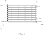
- FIG. 4 is a top view of a liquid cooling assembly provided by the embodiments of the present disclosure.
- FIG. 5 is a schematic cross-sectional view of a cooling plate provided by the embodiments of the present disclosure.
- the tray 21 includes a baseplate 211 and a plurality of cooling plates 22 located on the baseplate 211.
- the plurality of cooling plates 22 are arranged at intervals along the first direction X.
- One cell accommodating groove 21A is located between adjacent cooling plates 22.
- the tray 21 and the cooling plates 22 may be integrally formed.
- the cooling plates 22 and the current collectors 24 may be fixed by welding, thereby simplifying the structure of the tray 21 and reducing costs.
- the cooling plate 22 includes a plurality of coolant flow channels 221.
- the plurality of coolant flow channels 221 are arranged at intervals along the third direction Z.
- the coolant flow channels 221 penetrate the cooling plate 22 along the second direction Y. Both ends of the coolant flow channel 221 are provided with a liquid inlet port 221A and a liquid outlet port 221B, respectively.
- the liquid inlet port 221A is in communication with the liquid inlet hole 24A.
- Aliquid outlet port 221B is in communication with the liquid outlet hole 24B.
- the third direction is marked by Z.
- the third direction Z is provided perpendicular to the first direction X.
- the third direction Z is provided perpendicular to the second direction Y.
- the battery module 1 includes a plurality of first current collectors 241 and a plurality of second current collectors 242.
- the first current collectors 241 are provided with the liquid inlet hole 24A.
- the second current collectors 242 are provided with the liquid outlet hole 24B.
- Both ends of the coolant flow channel 221 are provided with a liquid inlet 221A and a liquid outlet 221B, respectively.
- the liquid inlet port 221A is in communication with the first current collectors 241.
- the liquid outlet port 221B is in communication with the second current collectors 242.
- the coolant flow channel 221 is preferably a linear channel. The coolant circulates in and out of the cooling plate 22 through the liquid inlet hole 24A, the liquid inlet port 221A, the coolant flow channel 221, the liquid outlet port 221B, and the liquid outlet hole 24B.
- the coolant flow channel 221 is provided in the side wall of the cell accommodating tank 21A, that is, in the cooling plate 22, the coolant flow channel 221 and the tray 21 are integrated into a whole.
- the cooling plate 22 is filled with coolant, and the coolant circulates in and out of the cooling plate 22 through the liquid inlet hole 24A, the liquid inlet port 221A, the coolant flow channel 221, the liquid outlet port 221B, and the liquid outlet hole 24B, so that liquid cooling heat dissipation of the cell 111 can be achieved.
- the cell 111 includes a first side surface 111A and a second side surface 111B.
- the first side surface 111A is disposed close to a side wall of the cell accommodating groove 21A.
- the second side surface 111B is located between adjacent cells 111.
- a length of the first side surface 111A is greater than a length of the second side surface 111B.
- the battery module 1 further includes a plurality of heat insulating layers 12 and a plurality of thermally conductive structural adhesives 13.
- the heat insulating layer 12 is located between the second side surfaces 111B of the adjacent cells 111.
- the thermally conductive structural adhesive 13 is located between the side wall of the cell accommodating groove 21A and the cell 111.
- the heat insulating layer 12 is preferably one or more of a fiber layer, a heat insulating foam, a heat insulating cotton, and a heat conductive adhesive.
- the cell 111 is a square shell cell.
- the cooling plate 22 has a flat structure to be adapted to the first side surface 111A of the square shell cell. It can be understood that in some embodiments, by providing the heat insulating layer 12 to be filled between the adjacent cells 111, the cooling efficiency of the cells 111 is improved. Further, by providing the thermally conductive structural adhesive 13 to be filled between the cell 111 and the cooling plate 22, the cell 111 and the cooling plate 22 are closely attached to each other, thereby improving the tightness and stiffness of the liquid cooling assembly 20, thereby preventing the cell 111 from expanding to affect the service life of the battery module 1. In some embodiments, a structural adhesive (not shown in the figure) may also be used to fixedly connect the cell 111 with the tray 21. The connection is convenient and reliable, and the cell 111 is effectively prevented from loosening and falling off.
- the cell 111 includes a thermal runaway nozzle.
- the thermal runaway nozzle is provided correspondingly to the explosion-proof valve 111C.
- the explosion-proof valve 111C is installed on the thermal runaway nozzle. It can be understood that when thermal runaway occurs in one of the cells 111 on the tray 21, the chemicals and gases of the cell 111 are directionally ejected from the thermal runaway nozzle.
- the thermal runaway nozzle of the cell 111 is aligned with the pressure relief hole 210, so that both the chemicals and gases of the cell 111 are directionally ejected into the pressure relief hole 210, thereby releasing pressure from the pressure relief hole 210 to the outside of the battery module 1.
- FIG. 6 is a schematic structural view of a battery pack provided by some embodiments of the present disclosure.
- FIG. 7 is a cross-sectional top view of the battery pack provided by some embodiments of the present disclosure.
- the present embodiments provide a battery pack 2 including a box 2A and a plurality of cell modules 2B.
- the box 2A includes a bottom plate 2A1 and a plurality of side beams 2A2.
- the plurality of side beams 2A2 are fixedly arranged on the edges of the bottom plate 2A1 to enclose to form a accommodation cavity 2C.
- the plurality of cell modules 2B are located in the accommodation cavity 2C.
- the plurality of cell modules 2B are arranged at intervals along the first direction X.
- the plurality of cell module 2B includes a plurality of cell modules 1 arranged at intervals along the second direction Y.
- the battery modules 1 include the battery module 1 described in any one of the above embodiments.
- the plurality of side beams 2A2 are sequentially connected to enclose to form a plurality of annular structures 2D.
- the annular structures 2D and the battery modules 1 are in one-to-one correspondence.
- the annular structures 2D are disposed around the battery modules 1.
- the bottom plate 2A1 and the plurality of side beams 2A2 form a plurality of accommodating sub cavities 2C1 for placing the battery modules 1.
- One of the accommodating sub cavities 2C1 is provided corresponding to one of the battery modules 1.
- the technical solution of the present disclosure is illustrated by taking the battery pack 2 including a first battery module 1A, a second battery module 1B, a third battery module 1C, and a fourth battery module 1D as an example.
- the plurality of cooling plates 22 include two first cooling plates 22A and a plurality of second cooling plates 22B.
- the two first cooling plates 22A are disposed opposite each other along the first direction X.
- the plurality of second cooling plates 22B are disposed between the two first cooling plates 22A at intervals.
- the first cooling plate 22A includes an extension portion 22A1 extending from an end of the first cooling plate 22A towards a direction away from the second cooling plate 22B, and the extension portion 22A1 is fixedly connected to the side beam 2A2.
- the extension portion 22A1 includes a plurality of first openings 22A11 provided at intervals along the second direction Y.
- the side beam 2A2 includes a plurality of second openings provided at intervals along the second direction Y.
- the first openings 22A11 and the second openings are in one-to-one correspondence.
- the extension portion 22A1 and the side beam 2A2 are connected by threads.
- the first cooling plate 22A includes an extension portion 22A1, the extension portion 22A1 extends from the end of the first cooling plate 22A towards the direction away from the second cooling plate 22B, and the extension portion 22A1 is fixedly connected to the side beam 2A2, so that the battery module 1 is limited, the battery module 1 can be prevented from moving when the battery pack 2 is subjected to external impact, and the stability of the battery pack 2 can be improved.
- the extension portion 22A1 and the side beam 2A2 by providing a threaded connection between the extension portion 22A1 and the side beam 2A2, the disassembly, assembly and maintenance are facilitated.
- the box 2A further includes a liquid outlet pipeline 2A4 located between adjacent cell modules 2B, and two liquid inlet pipelines 2A3 opposite each other along the first direction X.
- the liquid inlet pipeline 2A3 is located on a side of the battery module 1 away from the liquid outlet pipeline 2A4.
- the liquid outlet pipeline 2A4 is provided with a plurality of liquid outlet openings 2A41 sequentially arranged along the second direction Y.
- the liquid inlet pipeline 2A3 is provided with a plurality of liquid inlet openings 2A31 sequentially arranged along the second direction Y.
- one of the liquid inlet openings 2A31 is provided corresponding to one of the first cooling plates 22A, and the liquid inlet opening 2A31 is in communication with the liquid inlet hole 24A of the current collector 24 corresponding to the one of the first cooling plates 22A.
- One of the liquid outlet openings 2A41 is provided corresponding to the other of the first cooling plates 22A, and the liquid outlet opening 2A41 is in communication with the liquid outlet hole 24B of the current collector 24 corresponding to the other of first cooling plate 22A.
- the liquid inlet pipeline 2A3 includes a liquid inlet nozzle 2A32
- the liquid outlet pipeline 2A4 includes a liquid outlet nozzle 2A42.
- the liquid inlet nozzle 2A32 is connected to an external device (not shown in the figure), and the liquid outlet nozzle 2A42 is connected to an external device.
- the external device is a conventional device, and is capable of supplying a coolant to the liquid cooling module 20 and recovering the coolant flowing out of the liquid cooling module 20.
- the coolant enters the cooling plate 22 from the liquid inlet nozzle 2A32.
- the coolant circulates in and out of the cooling plate 22 through the liquid inlet hole 24A and the liquid outlet hole 24B.
- the coolant flows back from the liquid outlet nozzle 2A42 to the external device.
- the flow direction of the coolant is: a1 ⁇ b1 ⁇ c1 ⁇ d1 ⁇ e1.
- the flow direction of the coolant is: a1 ⁇ b2 ⁇ c2 ⁇ d2 ⁇ e2.
- the flow direction of the coolant is: a2 ⁇ b3 ⁇ c3 ⁇ d3 ⁇ e2.
- the flow direction of the coolant is: a2 ⁇ b4 ⁇ c4 ⁇ d4 ⁇ e2.
- the box 2A further includes a liquid outlet pipeline 2A4 located between the adjacent cell modules 2B and two liquid inlet pipelines 2A3 opposite each other along the first direction X, so that the structure is simplified, the installation space is reduced, the disassembly, assembly and maintenance are facilitated, and the cost is also reduced. Further, the coolant flows in from both sides of the box 2A and then flows out between the adjacent cell modules 2B, thereby reducing the flow resistance of the coolant inlet in the liquid cooling assembly 20 and improving the heat dissipation effect of the cooling plate 22.
- the coolant flows from the liquid inlet pipeline 2A3 on both sides into the cooling plate 22 of each module and then collects in the liquid outlet pipeline 2A4 in the middle portion.
- the space is saved, and the temperature uniformity of heat dissipation can be improved by the way of collecting from both sides to the middle portion.
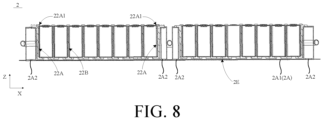
- FIG. 8 is a schematic cross-sectional view of a battery pack provided by the embodiments of the present disclosure.
- the tray 21, the bottom plate 2A1, and the side beam 2A2 are surrounded to form a pressure relief channel 2E.
- the pressure relief hole 210 is in communication with the pressure relief channel 2E.
- the hole diameter of the pressure relief hole 210 is smaller than the diameter of the cell 111.
- the design of the pressure relief channel 2E reduces the impact generated when the cell 111 bursts, and improves the safety of the operation of the battery module 1.
- providing the pressure relief hole 210 can quickly dissipate the heat of the cell 111 or the gas generated when thermal runaway occurs in the battery from the bottom of the cell 111.
- the heat dissipation effect is enhanced, the safety performance of the structure of the battery pack 2 is increased, the gas pressure inside the battery pack 2 is reduced, and the gas generated by the cell 111 is prevented from entering the accommodation cavity 2C, thereby ensuring that the temperature of the accommodation cavity 2C does not rise rapidly.
- a material of the box 2A is a metal.
- the tray 21 is made of plastic or other material with good insulation, which can prevent the bottom surface of the cell 111 from coming into contact with the bottom plate 2A1 and play an insulation protection role.
- a mica plate may also be provided between the tray 21 and the bottom plate 2A1, and the mica plate covers the pressure relief hole 210. The chemicals and gases sprayed by the cells 111 are sprayed onto the mica plate first, thereby preventing the box 2A from being burned through.
- the present embodiments provide an electrical device including the battery module in any one of the above embodiments.
- the electrical device includes the battery module, and the battery module is used as a power supply for the electrical device. Therefore, the electrical device also has various advantages of the battery module, thereby helping to simplify the overall structure of the electrical device.
- the electrical device may be an automobile, an aircraft, a mechanical production apparatus, or the like.
Landscapes
- Chemical & Material Sciences (AREA)
- Chemical Kinetics & Catalysis (AREA)
- Electrochemistry (AREA)
- General Chemical & Material Sciences (AREA)
- Engineering & Computer Science (AREA)
- Manufacturing & Machinery (AREA)
- Aviation & Aerospace Engineering (AREA)
- Secondary Cells (AREA)
- Battery Mounting, Suspending (AREA)
- Connection Of Batteries Or Terminals (AREA)
- Gas Exhaust Devices For Batteries (AREA)
Abstract
Description
- This application claims priority to
Chinese Patent Application No. 202321591191.4 submitted to the Chinese Patent Office on June 20, 2023 - The present disclosure relates to the technical field of batteries, in particular to a battery module and a battery pack.
- As one of the core components of electric vehicles, power batteries are the energy center of electric vehicles. As power battery technology becomes more and more widely used, the market puts forward higher requirements for the cruising range and safety of power batteries.
- At present, group technology of the commonly used power battery pack in the industry is cell to pack (CTP) technology, that is, CTP technology is adopted without the need for end plates, side plates or straps. CTP technology reduces costs and improves product cost performance. However, the power battery will generate a significant amount of heat during the charging and discharging process. In order to ensure the service life of the power battery, it needs to dispose an additional liquid cooling plate on the cell tray to dissipate heat from the battery module in related technologies, resulting in complicated battery system design and high cost.
- The embodiments of the present disclosure provide a battery module and a battery pack for solving or at least partially solving the shortcomings of the above background.
- The embodiments of the present disclosure provide a battery module, including:
- a cell assembly including a plurality of cell sub groups disposed at intervals along a first direction, in which each of the cell sub groups includes a plurality of cells, and the plurality of cells in any one of the cell sub groups are disposed at intervals along a second direction; and
- a tray including a plurality of cell accommodating grooves disposed at intervals along the first direction, in which one of the cell accommodating grooves is provided corresponding to one of the cell sub groups, and a coolant flow channel is arranged in a side wall of each of the cell accommodating grooves.
- The embodiments of the present disclosure provide a battery pack, including:
- a box including a bottom plate and a plurality of side beams, in which the plurality of side beams are fixedly arranged on edges of the bottom plate to enclose to form an accommodation cavity; and
- a plurality of cell modules located in the accommodation cavity, in which the plurality of cell modules are disposed at intervals along a first direction, each of the cell modules includes a plurality of battery modules disposed at intervals along a second direction, and the battery modules include the battery module described above.
- Beneficial effects of the embodiments of the present disclosure: The embodiment of the present disclosure provides a battery module and a battery pack. The battery module includes a cell assembly and a tray. The cell assembly includes a plurality of cell groups arranged at intervals along a first direction. Each of the cell groups includes a plurality of cells arranged at intervals along a second direction. The tray includes a plurality of cell accommodating grooves arranged at intervals along the first direction. One of the cell accommodating grooves is arranged corresponding to one of the cell sub groups. A coolant flow channel is arranged in a side wall of each of the cell accommodating grooves. By providing a coolant flow channel in the side wall of the cell accommodating groove, the coolant flow channel and the tray are integrated into a whole. There is no need to additionally provide a liquid cooling plate. The structure is more simplified, the space utilization of the battery module can be effectively improved, and the manufacturing cost of the battery module can be reduced.
-
-
FIG. 1 is a schematic structural view of a battery module provided by some embodiments of the present disclosure. -
FIG. 2 is an explosion view of the battery module provided by some embodiments of the present disclosure. -
FIG. 3 is a schematic cross-sectional view at a position A-A' inFIG. 1 . -
FIG. 4 is a top view of a liquid cooling assembly provided by some embodiments of the present disclosure. -
FIG. 5 is a schematic cross-sectional view of a cooling plate provided by some embodiments of the present disclosure. -
FIG. 6 is a schematic structural view of a battery pack provided by some embodiments of the present disclosure. -
FIG. 7 is a cross-sectional top view of the battery pack provided by some embodiments of the present disclosure. -
FIG. 8 is a schematic cross-sectional view of the battery pack provided by some embodiments of the present disclosure. -
- 1, battery module; 10, cell assembly; 20, liquid cooling assembly;
- 11, cell sub group; 12, heat insulating layer; 13, thermally conductive structural adhesive;
- 111, cell; 111A, first side surface; 111B, second side surface; 111C, explosion-proof valve;
- 21, tray; 22, cooling plate; 23, connecting member; 24, current collector;
- 21A, cell accommodating groove; 211, baseplate; 231, bellows; 241, first current collector; 242, second current collector; 210, pressure relief hole;
- 221 coolant flow channel; 221A, liquid inlet port; 221B, liquid outlet port; 24A, liquid inlet hole; 24B, liquid outlet hole;
- 2, battery pack; 2A, box; 2B, cell module; 2C, accommodation cavity; 2D, annular structure; 2E, pressure relief channel;
- 2A1, bottom plate; 2A2, side beam; 2A3, liquid inlet pipelines; 2A4, liquid outlet pipelines; 2C1, accommodating sub cavity;
- 2A31, liquid inlet opening; 2A32, liquid inlet nozzle; 2A41, liquid outlet opening; 2A42, liquid outlet nozzle;
- 1A, first battery module; 1B, second battery module; 1C, third battery module; 1D, fourth battery module; 22A, first cooling plate; 22B second cooling plate; 22A1 extension portion; 22A11, first opening.
- In the description of the present disclosure, it should be understood that, unless specified or limited otherwise, the terms "connected" and "coupled" are used broadly, and may be, for example, fixed connections or detachable connections; may also be mechanical connections or electrical connections; may also be direct connections or indirect connections via intervening structures; may also be inner communications of two elements or interaction relationships between two elements. For those ordinary skilled in the art, the specific meanings of the above-mentioned terms in the present disclosure can be understood on a case-by-case basis.
- In the description of the present disclosure, unless specified or limited otherwise, a structure in which a first feature is "on" or "below" a second feature may include an embodiment in which the first feature is in direct contact with the second feature, and may also include an embodiment in which the first feature and the second feature are not in direct contact with each other, but are contacted via an additional feature formed therebetween. Furthermore, a first feature "on", "above", or "on top of" a second feature may include an embodiment in which the first feature is right or obliquely "on", "above", or "on top of" the second feature, or just means that the first feature is at a height higher than that of the second feature. A first feature "below", "under", or "on bottom of" a second feature may include an embodiment in which the first feature is right or obliquely "below", "under", or "on bottom of" the second feature, or just means that the first feature is at a height lower than that of the second feature.
- The embodiments of the present disclosure provide a battery module and a battery pack. Hereinafter, each of them will be described in detail. It should be noted that the order of description of the following embodiments is not intended to limit the preferred order of the embodiments.
- Referring to
FIGS. 1 to 8 , a battery module, a battery pack, and an electrical device are provided by some embodiments. Thebattery module 1 includes acell assembly 10 and atray 21. Thecell assembly 10 includes a plurality ofcell sub groups 11. The plurality ofcell sub groups 11 are arranged at intervals along a first direction X. Thecell sub group 11 includes a plurality ofcells 111. In any one of thecell sub groups 11, the plurality ofcells 111 are arranged at intervals along a second direction Y. Thetray 21 includes a plurality ofcell accommodating grooves 21A arranged at intervals along the first direction X. One cell accommodating groove is arranged corresponding to onecell sub group 11. Acoolant flow channel 221 is arranged in a side wall of thecell accommodating groove 21A. - It should be noted that, in related technologies, group technology of the commonly used power battery pack in the industry is cell to pack (CTP) technology, that is, CTP technology is adopted without the need for end plates, side plates or straps. CTP technology reduces costs and improves product cost performance. However, the power battery will generate a significant amount of heat during the charging and discharging process. In order to ensure the service life of the power battery, it is need to dispose an additional liquid cooling plate on the cell tray to dissipate heat from the battery module, resulting in complicated battery system design and high cost.
- It can be understood that in the embodiments, by providing the
coolant flow channel 221 in the side wall of thecell accommodating groove 21A, thecoolant flow channel 221 and thetray 21 are integrated into a whole without providing an additional liquid cooling plate. The structure is more simplified, the space utilization of thebattery module 1 can be effectively improved, and the manufacturing cost of thebattery module 1 can be reduced. - The technical solutions of the present disclosure will be described hereinafter with reference to the specific embodiments.
- In some embodiments, referring to
FIGS. 1 and2 ,FIG. 1 is a schematic structural view of the battery module provided by the embodiments of the present disclosure, andFIG. 2 is an explosion view of the battery module provided by the embodiments of the present disclosure. - The embodiments provide a
battery module 1 including acell assembly 10 and atray 21. Thecell assembly 10 includes a plurality of cell sub groups 11. The plurality ofcell sub groups 11 are arranged at intervals along a first direction X. Thecell sub group 11 includes a plurality ofcells 111. In any one of thecell sub groups 11, the plurality ofcells 111 are arranged at intervals along a second direction Y. Thetray 21 includes a plurality ofcell accommodating grooves 21A arranged at intervals along the first direction X. One cell accommodating groove is arranged corresponding to onecell sub group 11. Acoolant flow channel 221 is arranged in a side wall of thecell accommodating groove 21A. - In some embodiments, the
battery module 1 further includes a plurality ofcurrent collectors 24 disposed at both ends of the side wall of thecell accommodating groove 21A. A plurality of connectingmembers 23 are disposed between adjacentcurrent collectors 24. Thecurrent collectors 24 on one side are provided with aliquid inlet hole 24A, and thecurrent collectors 24 on another side are provided with aliquid outlet hole 24B. When thebattery module 1 is in a usage state, thecoolant flow channel 221 is filled with coolant, and the coolant circulates in and out of thecoolant flow channel 221 through theliquid inlet hole 24A and theliquid outlet hole 24B. The connectingmember 23 includes, but is not limited to, a bellows 231. - It should be noted that, in the present disclosure, the first direction is marked by X, the second direction is marked by Y, and the first direction X and the second direction Y form a preset included angle. In some embodiments, the present disclosure is illustrated by taking the preset included angle as a right angle as an example.
- In some embodiments, referring to
FIGS. 2 ,3 ,4 , and5 .FIG. 3 is a schematic cross-sectional view at position A-A' inFIG. 1 .FIG. 4 is a top view of a liquid cooling assembly provided by the embodiments of the present disclosure.FIG. 5 is a schematic cross-sectional view of a cooling plate provided by the embodiments of the present disclosure. - The
tray 21 includes a baseplate 211 and a plurality of coolingplates 22 located on the baseplate 211. The plurality of coolingplates 22 are arranged at intervals along the first direction X. One cell accommodating groove 21Ais located betweenadjacent cooling plates 22. Thetray 21 and thecooling plates 22 may be integrally formed. The coolingplates 22 and thecurrent collectors 24 may be fixed by welding, thereby simplifying the structure of thetray 21 and reducing costs. - In some embodiments, the cooling
plate 22 includes a plurality ofcoolant flow channels 221. The plurality ofcoolant flow channels 221 are arranged at intervals along the third direction Z. Thecoolant flow channels 221 penetrate thecooling plate 22 along the second direction Y. Both ends of thecoolant flow channel 221 are provided with aliquid inlet port 221A and aliquid outlet port 221B, respectively. Theliquid inlet port 221A is in communication with theliquid inlet hole 24A.Aliquid outlet port 221B is in communication with theliquid outlet hole 24B. - It should be noted that in the present disclosure, the third direction is marked by Z. The third direction Z is provided perpendicular to the first direction X. The third direction Z is provided perpendicular to the second direction Y.
- Specifically, the
battery module 1 includes a plurality of firstcurrent collectors 241 and a plurality of secondcurrent collectors 242. The firstcurrent collectors 241 are provided with theliquid inlet hole 24A. The secondcurrent collectors 242 are provided with theliquid outlet hole 24B. Both ends of thecoolant flow channel 221 are provided with aliquid inlet 221A and aliquid outlet 221B, respectively. Theliquid inlet port 221A is in communication with the firstcurrent collectors 241. Theliquid outlet port 221B is in communication with the secondcurrent collectors 242. Thecoolant flow channel 221 is preferably a linear channel. The coolant circulates in and out of the coolingplate 22 through theliquid inlet hole 24A, theliquid inlet port 221A, thecoolant flow channel 221, theliquid outlet port 221B, and theliquid outlet hole 24B. - It can be understood that in the embodiments, the
coolant flow channel 221 is provided in the side wall of the cellaccommodating tank 21A, that is, in thecooling plate 22, thecoolant flow channel 221 and thetray 21 are integrated into a whole. The coolingplate 22 is filled with coolant, and the coolant circulates in and out of the coolingplate 22 through theliquid inlet hole 24A, theliquid inlet port 221A, thecoolant flow channel 221, theliquid outlet port 221B, and theliquid outlet hole 24B, so that liquid cooling heat dissipation of thecell 111 can be achieved. There is no need to provide an additional liquid cooling plate in the related art, so that the space utilization of thebattery module 1 can be effectively improved, and the manufacturing cost of thebattery module 1 can be reduced. - In some embodiments, the
cell 111 includes afirst side surface 111A and asecond side surface 111B. Thefirst side surface 111A is disposed close to a side wall of thecell accommodating groove 21A. Thesecond side surface 111B is located betweenadjacent cells 111. A length of thefirst side surface 111A is greater than a length of thesecond side surface 111B. Thebattery module 1 further includes a plurality ofheat insulating layers 12 and a plurality of thermally conductivestructural adhesives 13. Theheat insulating layer 12 is located between the second side surfaces 111B of theadjacent cells 111. The thermally conductivestructural adhesive 13 is located between the side wall of thecell accommodating groove 21A and thecell 111. Theheat insulating layer 12 is preferably one or more of a fiber layer, a heat insulating foam, a heat insulating cotton, and a heat conductive adhesive. - In some embodiments, the
cell 111 is a square shell cell. The coolingplate 22 has a flat structure to be adapted to thefirst side surface 111A of the square shell cell. It can be understood that in some embodiments, by providing theheat insulating layer 12 to be filled between theadjacent cells 111, the cooling efficiency of thecells 111 is improved. Further, by providing the thermally conductive structural adhesive 13 to be filled between thecell 111 and the coolingplate 22, thecell 111 and the coolingplate 22 are closely attached to each other, thereby improving the tightness and stiffness of theliquid cooling assembly 20, thereby preventing thecell 111 from expanding to affect the service life of thebattery module 1. In some embodiments, a structural adhesive (not shown in the figure) may also be used to fixedly connect thecell 111 with thetray 21. The connection is convenient and reliable, and thecell 111 is effectively prevented from loosening and falling off. - It should be noted that an explosion-proof valve 111C is provided on a side of the
cell 111 close to the baseplate 211. The baseplate 211 is provided with a plurality of pressure relief holes 210. Thepressure relief holes 210 penetrate the baseplate 211 along the thickness direction of the baseplate. Onepressure relief hole 210 is provided corresponding to one explosion-proof valve 111C. One end of thecell 111 provided with the explosion-proof valve 111C is in communication with thepressure relief hole 210. - Specifically, the
cell 111 includes a thermal runaway nozzle. The thermal runaway nozzle is provided correspondingly to the explosion-proof valve 111C. The explosion-proof valve 111C is installed on the thermal runaway nozzle. It can be understood that when thermal runaway occurs in one of thecells 111 on thetray 21, the chemicals and gases of thecell 111 are directionally ejected from the thermal runaway nozzle. The thermal runaway nozzle of thecell 111 is aligned with thepressure relief hole 210, so that both the chemicals and gases of thecell 111 are directionally ejected into thepressure relief hole 210, thereby releasing pressure from thepressure relief hole 210 to the outside of thebattery module 1. - In some embodiments, referring to
FIGS. 1 ,4 ,6 , and7 .FIG. 6 is a schematic structural view of a battery pack provided by some embodiments of the present disclosure.FIG. 7 is a cross-sectional top view of the battery pack provided by some embodiments of the present disclosure. - The present embodiments provide a
battery pack 2 including abox 2A and a plurality ofcell modules 2B. Thebox 2A includes a bottom plate 2A1 and a plurality of side beams 2A2. The plurality of side beams 2A2 are fixedly arranged on the edges of the bottom plate 2A1 to enclose to form aaccommodation cavity 2C. The plurality ofcell modules 2B are located in theaccommodation cavity 2C. The plurality ofcell modules 2B are arranged at intervals along the first direction X. The plurality ofcell module 2B includes a plurality ofcell modules 1 arranged at intervals along the second direction Y. Thebattery modules 1 include thebattery module 1 described in any one of the above embodiments. - It can be understood that the
battery module 1 has been described in detail in the above embodiments, and the description will not be repeated here. - In some embodiments, the plurality of side beams 2A2 are sequentially connected to enclose to form a plurality of annular structures 2D. The annular structures 2D and the
battery modules 1 are in one-to-one correspondence. The annular structures 2D are disposed around thebattery modules 1. Specifically, the bottom plate 2A1 and the plurality of side beams 2A2 form a plurality of accommodating sub cavities 2C1 for placing thebattery modules 1. One of the accommodating sub cavities 2C1 is provided corresponding to one of thebattery modules 1. - It should be noted that in the embodiments, the technical solution of the present disclosure is illustrated by taking the
battery pack 2 including afirst battery module 1A, asecond battery module 1B, athird battery module 1C, and a fourth battery module 1D as an example. - In some embodiments, in any one of the
battery modules 1, the plurality of coolingplates 22 include twofirst cooling plates 22A and a plurality ofsecond cooling plates 22B. The twofirst cooling plates 22A are disposed opposite each other along the first direction X. The plurality ofsecond cooling plates 22B are disposed between the twofirst cooling plates 22A at intervals. Thefirst cooling plate 22A includes an extension portion 22A1 extending from an end of thefirst cooling plate 22A towards a direction away from thesecond cooling plate 22B, and the extension portion 22A1 is fixedly connected to the side beam 2A2. - Specifically, the extension portion 22A1 includes a plurality of first openings 22A11 provided at intervals along the second direction Y. The side beam 2A2 includes a plurality of second openings provided at intervals along the second direction Y. The first openings 22A11 and the second openings (not shown in the figure) are in one-to-one correspondence. The extension portion 22A1 and the side beam 2A2 are connected by threads.
- It can be understood that in the embodiments, the
first cooling plate 22A includes an extension portion 22A1, the extension portion 22A1 extends from the end of thefirst cooling plate 22A towards the direction away from thesecond cooling plate 22B, and the extension portion 22A1 is fixedly connected to the side beam 2A2, so that thebattery module 1 is limited, thebattery module 1 can be prevented from moving when thebattery pack 2 is subjected to external impact, and the stability of thebattery pack 2 can be improved. In addition, by providing a threaded connection between the extension portion 22A1 and the side beam 2A2, the disassembly, assembly and maintenance are facilitated. - In some embodiments, the
box 2A further includes a liquid outlet pipeline 2A4 located betweenadjacent cell modules 2B, and two liquid inlet pipelines 2A3 opposite each other along the first direction X. The liquid inlet pipeline 2A3 is located on a side of thebattery module 1 away from the liquid outlet pipeline 2A4. The liquid outlet pipeline 2A4 is provided with a plurality of liquid outlet openings 2A41 sequentially arranged along the second direction Y. The liquid inlet pipeline 2A3 is provided with a plurality of liquid inlet openings 2A31 sequentially arranged along the second direction Y. In any one of thebattery modules 1, one of the liquid inlet openings 2A31 is provided corresponding to one of thefirst cooling plates 22A, and the liquid inlet opening 2A31 is in communication with theliquid inlet hole 24A of thecurrent collector 24 corresponding to the one of thefirst cooling plates 22A. One of the liquid outlet openings 2A41 is provided corresponding to the other of thefirst cooling plates 22A, and the liquid outlet opening 2A41 is in communication with theliquid outlet hole 24B of thecurrent collector 24 corresponding to the other offirst cooling plate 22A. - Specifically, the liquid inlet pipeline 2A3 includes a liquid inlet nozzle 2A32, and the liquid outlet pipeline 2A4 includes a liquid outlet nozzle 2A42. The liquid inlet nozzle 2A32 is connected to an external device (not shown in the figure), and the liquid outlet nozzle 2A42 is connected to an external device. However, the external device is a conventional device, and is capable of supplying a coolant to the
liquid cooling module 20 and recovering the coolant flowing out of theliquid cooling module 20. - In some embodiments, the coolant enters the cooling
plate 22 from the liquid inlet nozzle 2A32. The coolant circulates in and out of the coolingplate 22 through theliquid inlet hole 24A and theliquid outlet hole 24B. The coolant flows back from the liquid outlet nozzle 2A42 to the external device. In thefirst battery module 1A, the flow direction of the coolant is: a1 → b1 → c1 → d1 → e1. In thesecond battery module 1B, the flow direction of the coolant is: a1 → b2 → c2 → d2 → e2. In thethird battery module 1C, the flow direction of the coolant is: a2 → b3 → c3 → d3 → e2. In the fourth battery module 1D, the flow direction of the coolant is: a2 → b4 → c4 → d4 → e2. - It can be understood that in the embodiments, the
box 2A further includes a liquid outlet pipeline 2A4 located between theadjacent cell modules 2B and two liquid inlet pipelines 2A3 opposite each other along the first direction X, so that the structure is simplified, the installation space is reduced, the disassembly, assembly and maintenance are facilitated, and the cost is also reduced. Further, the coolant flows in from both sides of thebox 2A and then flows out between theadjacent cell modules 2B, thereby reducing the flow resistance of the coolant inlet in theliquid cooling assembly 20 and improving the heat dissipation effect of the coolingplate 22. In addition, by providing the liquid outlet pipeline 2A4 to be between the twocell modules 2B, the coolant flows from the liquid inlet pipeline 2A3 on both sides into the coolingplate 22 of each module and then collects in the liquid outlet pipeline 2A4 in the middle portion. Just one liquid outlet pipeline 2A4 is needed to realize backflow, the space is saved, and the temperature uniformity of heat dissipation can be improved by the way of collecting from both sides to the middle portion. - In some embodiments, referring to
FIGS. 3 ,6 ,7 , and8, FIG. 8 is a schematic cross-sectional view of a battery pack provided by the embodiments of the present disclosure. - The
tray 21, the bottom plate 2A1, and the side beam 2A2 are surrounded to form apressure relief channel 2E. Thepressure relief hole 210 is in communication with thepressure relief channel 2E. Specifically, the hole diameter of thepressure relief hole 210 is smaller than the diameter of thecell 111. The design of thepressure relief channel 2E reduces the impact generated when thecell 111 bursts, and improves the safety of the operation of thebattery module 1. In addition, providing thepressure relief hole 210 can quickly dissipate the heat of thecell 111 or the gas generated when thermal runaway occurs in the battery from the bottom of thecell 111. The heat dissipation effect is enhanced, the safety performance of the structure of thebattery pack 2 is increased, the gas pressure inside thebattery pack 2 is reduced, and the gas generated by thecell 111 is prevented from entering theaccommodation cavity 2C, thereby ensuring that the temperature of theaccommodation cavity 2C does not rise rapidly. - It should be noted that a material of the
box 2A is a metal. Thetray 21 is made of plastic or other material with good insulation, which can prevent the bottom surface of thecell 111 from coming into contact with the bottom plate 2A1 and play an insulation protection role. In addition, a mica plate may also be provided between thetray 21 and the bottom plate 2A1, and the mica plate covers thepressure relief hole 210. The chemicals and gases sprayed by thecells 111 are sprayed onto the mica plate first, thereby preventing thebox 2A from being burned through. - The present embodiments provide an electrical device including the battery module in any one of the above embodiments.
- It can be understood that the battery module has been described in detail in the above embodiments, and the description will not be repeated here.
- The electrical device includes the battery module, and the battery module is used as a power supply for the electrical device. Therefore, the electrical device also has various advantages of the battery module, thereby helping to simplify the overall structure of the electrical device. The electrical device may be an automobile, an aircraft, a mechanical production apparatus, or the like.
Claims (20)
- A battery module, comprising:a cell assembly comprising a plurality of cell sub groups disposed at intervals along a first direction, wherein each of the cell sub groups comprises a plurality of cells, and the plurality of cells in any one of the cell sub groups are disposed at intervals along a second direction; anda tray comprising a plurality of cell accommodating grooves disposed at intervals along the first direction, wherein one of the cell accommodating grooves is provided corresponding to one of the cell sub groups, and a coolant flow channel is arranged in a side wall of each of the cell accommodating grooves.
- The battery module of claim 1, wherein the battery module further comprises a plurality of current collectors disposed at both ends of the side wall of the each of the cell accommodating grooves and a plurality of connecting members disposed between adjacent two of the current collectors, ones of the current collectors on one side are provided with a liquid inlet hole, and ones of the current collectors on another side are provided with a liquid outlet hole.
- The battery module of claim 2, wherein the tray comprises a baseplate and a plurality of cooling plates located on the baseplate, the plurality of cooling plates are disposed at intervals along the first direction, one of the cell accommodating grooves is located between adjacent two of the cooling plates, and the baseplate is integrally formed with the cooling plates.
- The battery module of claim 3, wherein each of the cooling plates comprises a plurality of coolant flow channels, the plurality of the coolant flow channels are disposed at intervals along a third direction, and the coolant flow channels penetrate corresponding one of the cooling plates along the second direction; and
both ends of one of the coolant flow channels are provided with a liquid inlet port and a liquid outlet port, respectively, the liquid inlet port is in communication with the liquid inlet hole, and the liquid outlet port is in communication with the liquid outlet hole. - The battery module of claim 4, wherein the battery module comprises a plurality of first current collectors and a plurality of second current collectors, the first current collectors are provided with the liquid inlet hole, the second current collectors are provided with the liquid outlet hole, the liquid inlet port is in communication with the first current collectors, and the liquid outlet port is in communication with the second current collectors; and the coolant flow channels are linear channels.
- The battery module of claim 3, wherein a plurality of explosion-proof valves are provided on a side of the cells close to the baseplate, the baseplate is provided with a plurality of pressure relief holes, the pressure relief holes penetrate the baseplate, and one of the pressure relief holes is provided corresponding to one of the explosion-proof valves.
- The battery module of claim 6, wherein a hole diameter of one of the pressure relief holes is smaller than a diameter of one of the explosion-proof valves.
- The battery module of claim 1, wherein each of the cells comprises a first side surface and a second side surface, the first side surface is disposed close to a side wall of corresponding one of the cell accommodating grooves, the second side surface is located between adjacent two of the cells, and a length of the first side surface is greater than a length of the second side surface; and
the battery module further comprises a plurality of heat insulating layers and a plurality of thermally conductive structural adhesives, each of the heat insulating layers is located between second side surfaces of the adjacent two of the cells, and each of the thermally conductive structural adhesives is located between the side wall of corresponding one of the cell accommodating grooves and one of the cells. - A battery pack, comprising:a box comprising a bottom plate and a plurality of side beams, wherein the plurality of side beams are fixedly arranged on edges of the bottom plate to enclose to form an accommodation cavity; anda plurality of cell modules located in the accommodation cavity, wherein the plurality of cell modules are disposed at intervals along a first direction, each of the cell modules comprises a plurality of battery modules disposed at intervals along a second direction, each of the battery modules comprises a cell assembly and a tray;wherein the cell assembly comprises a plurality of cell sub groups disposed at intervals along the first direction, each of the cell sub groups comprises a plurality of cells, and the plurality of cells in any one of the cell sub groups are disposed at intervals along the second direction; andthe tray comprises a plurality of cell accommodating grooves arranged at intervals along the first direction, one of the cell accommodating grooves is provided corresponding to one of the cell sub groups, and a coolant flow channel is arranged in a side wall of each of the cell accommodating grooves.
- The battery pack of claim 9, wherein in any one of the battery modules, a plurality of cooling plates comprise two first cooling plates and a plurality of second cooling plates, the two first cooling plates are disposed opposite each other along the first direction, the plurality of second cooling plates are located between the two first cooling plates, each of the first cooling plates comprises an extension portion extending from an end of the first cooling plates towards a direction away from the second cooling plates, and the extension portion is fixedly connected to one of the side beams.
- The battery pack of claim 10, wherein the box further comprises a liquid outlet pipeline located between adjacent two of the cell modules and two liquid inlet pipelines opposite each other along the first direction, and each of the liquid inlet pipelines is located on a side of corresponding one of the battery modules away from the liquid outlet pipeline, the liquid outlet pipeline is provided with a plurality of liquid outlet openings sequentially arranged along the second direction, and each of the liquid inlet pipelines is provided with a plurality of liquid inlet openings sequentially arranged along the second direction;
in any one of the battery modules, one of the liquid inlet openings is provided corresponding to one of the first cooling plates, the one of the liquid inlet openings is in communication with a liquid inlet hole of a current collector corresponding to the one of the first cooling plates, one of the liquid outlet openings is provided corresponding to another of the first cooling plates, and the one of the liquid outlet openings is in communication with a liquid outlet hole of a current collector corresponding to the another of the first cooling plates. - The battery pack of claim 9, wherein the tray, the bottom plate, and the side beams are enclosed to form a pressure relief channel, and the pressure relief holes are in communication with the pressure relief channel.
- The battery pack of claim 12, wherein a hole diameter of one of the pressure relief holes is smaller than a diameter of one of the cells.
- The battery pack of claim 9, wherein the battery module further comprises a plurality of current collectors disposed at both ends of the side wall of the each of the cell accommodating grooves and a plurality of connecting members disposed between adjacent two of the current collectors, ones of the current collectors on one side are provided with a liquid inlet hole, and ones of the current collectors on another side are provided with a liquid outlet hole.
- The battery pack of claim 14, wherein the tray comprises a baseplate and a plurality of cooling plates located on the baseplate, the plurality of cooling plates are disposed at intervals along the first direction, one of the cell accommodating grooves is located between adjacent two of the cooling plates, and the baseplate is integrally formed with the cooling plates.
- The battery pack of claim 15, wherein each of the cooling plates comprises a plurality of coolant flow channels, the plurality of the coolant flow channels are disposed at intervals along a third direction, and the coolant flow channels penetrate corresponding one of the cooling plates along the second direction; and
both ends of one of the coolant flow channels are provided with a liquid inlet port and a liquid outlet port, respectively, the liquid inlet port is in communication with the liquid inlet hole, and the liquid outlet port is communication with the liquid outlet hole. - The battery pack of claim 16, wherein the battery module comprises a plurality of first current collectors and a plurality of second current collectors, the first current collectors are provided with the liquid inlet hole, the second current collectors are provided with the liquid outlet hole, the liquid inlet port is in communication with the first current collectors, and the liquid outlet port is in communication with the second current collectors; and the coolant flow channels are linear channels.
- The battery pack of claim 15, wherein a plurality of explosion-proof valves are provided on a side of the cells close to the baseplate, the baseplate is provided with a plurality of pressure relief holes, the pressure relief holes penetrate the baseplate, and one of the pressure relief holes is provided corresponding to one of the explosion-proof valves.
- The battery pack of claim 18, wherein one end of the cells provided with the explosion-proof valves are in communication with the pressure relief holes.
- The battery pack of claim 9, wherein each of the cells comprises a first side surface and a second side surface, the first side surface is disposed close to a side wall of corresponding one of the cell accommodating grooves, the second side surface is located between adjacent two of the cells, and a length of the first side surface is greater than a length of the second side surface; and
the battery module further comprises a plurality of heat insulating layers and a plurality of thermally conductive structural adhesives, each of the heat insulating layers is located between second side surfaces of the adjacent two of the cells, and each of the thermally conductive structural adhesives is located between the side wall of corresponding one of the cell accommodating grooves and one of the cells.
Applications Claiming Priority (2)
| Application Number | Priority Date | Filing Date | Title |
|---|---|---|---|
| CN202321591191.4U CN220021368U (en) | 2023-06-20 | 2023-06-20 | Battery module and battery pack |
| PCT/CN2023/132534 WO2024259885A1 (en) | 2023-06-20 | 2023-11-20 | Battery module and battery pack |
Publications (2)
| Publication Number | Publication Date |
|---|---|
| EP4513643A1 true EP4513643A1 (en) | 2025-02-26 |
| EP4513643A4 EP4513643A4 (en) | 2026-02-11 |
Family
ID=88681672
Family Applications (1)
| Application Number | Title | Priority Date | Filing Date |
|---|---|---|---|
| EP23936787.3A Pending EP4513643A4 (en) | 2023-06-20 | 2023-11-20 | BATTERY MODULE AND BATTERY PACK |
Country Status (6)
| Country | Link |
|---|---|
| US (1) | US20250140982A1 (en) |
| EP (1) | EP4513643A4 (en) |
| JP (1) | JP7841123B2 (en) |
| KR (1) | KR20240178257A (en) |
| CN (1) | CN220021368U (en) |
| WO (1) | WO2024259885A1 (en) |
Families Citing this family (3)
| Publication number | Priority date | Publication date | Assignee | Title |
|---|---|---|---|---|
| CN220021368U (en) * | 2023-06-20 | 2023-11-14 | 惠州亿纬锂能股份有限公司 | Battery module and battery pack |
| KR20250141972A (en) * | 2024-03-21 | 2025-09-30 | 주식회사 엘지에너지솔루션 | Pack housing of extrusion type and manufacturing method for the same |
| EP4647704A1 (en) * | 2024-05-10 | 2025-11-12 | Eve Energy Co., Ltd. | Cooling component and battery pack |
Family Cites Families (14)
| Publication number | Priority date | Publication date | Assignee | Title |
|---|---|---|---|---|
| DE102014200983B4 (en) * | 2014-01-21 | 2023-12-14 | Robert Bosch Gmbh | Battery system with several battery cells and a housing, housing system for a battery and method for assembling a battery system |
| KR102803108B1 (en) * | 2018-12-21 | 2025-05-07 | 아와 세이시 가부시키가이샤 | Power supply and insulation sheets for power supply |
| CN215299355U (en) * | 2021-07-30 | 2021-12-24 | 蜂巢能源科技有限公司 | Battery pack and cooling system for battery pack |
| EP4187698A1 (en) * | 2021-11-26 | 2023-05-31 | Volvo Car Corporation | Cooling system for single and multi-bay ev structural batteries |
| EP4354615A4 (en) * | 2021-11-30 | 2025-01-01 | Contemporary Amperex Technology (Hong Kong) Limited | BATTERY MODULE, BATTERY PACK, ELECTRICAL DEVICE AND METHOD FOR PRODUCING A BATTERY MODULE |
| WO2024031413A1 (en) * | 2022-08-10 | 2024-02-15 | 宁德时代新能源科技股份有限公司 | Battery and electrical device |
| CN116157948A (en) * | 2022-06-27 | 2023-05-23 | 宁德时代新能源科技股份有限公司 | Thermal management device, battery and electrical device |
| CN218123570U (en) * | 2022-09-23 | 2022-12-23 | 楚能新能源股份有限公司 | Battery module |
| CN218568986U (en) * | 2022-10-24 | 2023-03-03 | 湖北亿纬动力有限公司 | Module tray and battery module |
| CN218731481U (en) * | 2022-10-27 | 2023-03-24 | 赛格威科技有限公司 | Battery module shell, battery module and all-terrain vehicle |
| CN115441121B (en) * | 2022-11-08 | 2023-02-07 | 楚能新能源股份有限公司 | Battery module, battery package and electric motor car that delay thermal runaway |
| CN218632348U (en) * | 2022-11-22 | 2023-03-14 | 浙江极氪智能科技有限公司 | Battery package and car |
| CN115966808A (en) * | 2023-01-13 | 2023-04-14 | 惠州亿纬锂能股份有限公司 | Integrated side liquid cooling battery pack and electric automobile |
| CN220021368U (en) * | 2023-06-20 | 2023-11-14 | 惠州亿纬锂能股份有限公司 | Battery module and battery pack |
-
2023
- 2023-06-20 CN CN202321591191.4U patent/CN220021368U/en active Active
- 2023-11-20 EP EP23936787.3A patent/EP4513643A4/en active Pending
- 2023-11-20 KR KR1020247035775A patent/KR20240178257A/en active Pending
- 2023-11-20 WO PCT/CN2023/132534 patent/WO2024259885A1/en not_active Ceased
- 2023-11-20 JP JP2024564952A patent/JP7841123B2/en active Active
-
2024
- 2024-12-29 US US19/004,406 patent/US20250140982A1/en active Pending
Also Published As
| Publication number | Publication date |
|---|---|
| JP2025525283A (en) | 2025-08-05 |
| JP7841123B2 (en) | 2026-04-06 |
| US20250140982A1 (en) | 2025-05-01 |
| KR20240178257A (en) | 2024-12-30 |
| WO2024259885A1 (en) | 2024-12-26 |
| EP4513643A4 (en) | 2026-02-11 |
| CN220021368U (en) | 2023-11-14 |
Similar Documents
| Publication | Publication Date | Title |
|---|---|---|
| EP4513643A1 (en) | Battery module and battery pack | |
| CN219203266U (en) | Batteries and electrical devices | |
| US20250023199A1 (en) | Battery, electrical apparatus and battery forming method | |
| WO2023004720A1 (en) | Battery, electrical apparatus, and manufacturing system and manufacturing method for battery | |
| US12586843B2 (en) | Thermal management component, thermal management system, battery, and electric apparatus | |
| US20250079605A1 (en) | Thermal management component, battery, and electric apparatus | |
| US20250087831A1 (en) | Battery and electric apparatus | |
| WO2024124689A1 (en) | Battery and electrical device | |
| WO2024037655A1 (en) | Battery module upper cover structure, battery module, and battery pack | |
| CN118315747A (en) | Cylindrical battery pack and assembling method thereof | |
| US20250279504A1 (en) | Heat exchange assembly, battery and electrical device | |
| US20250246710A1 (en) | Heat exchanging assembly, battery module, battery, electrical device | |
| US20250293342A1 (en) | Battery and electric device | |
| US20250372799A1 (en) | Pressure relief assembly, battery module, battery pack, and powered device | |
| US20250309466A1 (en) | Pressure relief structure for double-layer battery and battery pack | |
| WO2024250694A1 (en) | Battery and electrical device | |
| CN114421086B (en) | Automobile power lithium ion battery module structure | |
| CN117895175A (en) | Battery modules and battery packs | |
| CN116365150A (en) | Battery components, battery packs and power equipment | |
| CN223296959U (en) | Battery pack and electric equipment | |
| CN222338392U (en) | New energy automobile's battery package assembly and new energy automobile | |
| CN218602557U (en) | Battery pack | |
| CN222690743U (en) | Battery and aircraft | |
| CN220774513U (en) | Heat exchange assembly, battery and electric equipment | |
| EP4657606A1 (en) | Pressure relief assembly, battery module, battery pack, and powered device |
Legal Events
| Date | Code | Title | Description |
|---|---|---|---|
| STAA | Information on the status of an ep patent application or granted ep patent |
Free format text: STATUS: UNKNOWN |
|
| STAA | Information on the status of an ep patent application or granted ep patent |
Free format text: STATUS: THE INTERNATIONAL PUBLICATION HAS BEEN MADE |
|
| PUAI | Public reference made under article 153(3) epc to a published international application that has entered the european phase |
Free format text: ORIGINAL CODE: 0009012 |
|
| STAA | Information on the status of an ep patent application or granted ep patent |
Free format text: STATUS: REQUEST FOR EXAMINATION WAS MADE |
|
| 17P | Request for examination filed |
Effective date: 20241119 |
|
| AK | Designated contracting states |
Kind code of ref document: A1 Designated state(s): AL AT BE BG CH CY CZ DE DK EE ES FI FR GB GR HR HU IE IS IT LI LT LU LV MC ME MK MT NL NO PL PT RO RS SE SI SK SM TR |
|
| A4 | Supplementary search report drawn up and despatched |
Effective date: 20260114 |
|
| RIC1 | Information provided on ipc code assigned before grant |
Ipc: H01M 50/209 20210101AFI20260108BHEP Ipc: H01M 50/244 20210101ALI20260108BHEP Ipc: H01M 50/249 20210101ALI20260108BHEP Ipc: H01M 50/258 20210101ALI20260108BHEP Ipc: H01M 10/613 20140101ALI20260108BHEP Ipc: H01M 10/625 20140101ALI20260108BHEP Ipc: H01M 10/6567 20140101ALI20260108BHEP Ipc: H01M 50/289 20210101ALI20260108BHEP Ipc: H01M 10/653 20140101ALI20260108BHEP Ipc: H01M 10/6557 20140101ALI20260108BHEP Ipc: H01M 10/658 20140101ALI20260108BHEP |