EP4513615A1 - Battery system and method of assembling a battery system - Google Patents
Battery system and method of assembling a battery system Download PDFInfo
- Publication number
- EP4513615A1 EP4513615A1 EP23193423.3A EP23193423A EP4513615A1 EP 4513615 A1 EP4513615 A1 EP 4513615A1 EP 23193423 A EP23193423 A EP 23193423A EP 4513615 A1 EP4513615 A1 EP 4513615A1
- Authority
- EP
- European Patent Office
- Prior art keywords
- printed circuit
- battery
- flat cable
- flexible flat
- circuit boards
- Prior art date
- Legal status (The legal status is an assumption and is not a legal conclusion. Google has not performed a legal analysis and makes no representation as to the accuracy of the status listed.)
- Granted
Links
Images


Classifications
-
- H—ELECTRICITY
- H01—ELECTRIC ELEMENTS
- H01M—PROCESSES OR MEANS, e.g. BATTERIES, FOR THE DIRECT CONVERSION OF CHEMICAL ENERGY INTO ELECTRICAL ENERGY
- H01M50/00—Constructional details or processes of manufacture of the non-active parts of electrochemical cells other than fuel cells, e.g. hybrid cells
- H01M50/50—Current conducting connections for cells or batteries
- H01M50/502—Interconnectors for connecting terminals of adjacent batteries; Interconnectors for connecting cells outside a battery casing
- H01M50/519—Interconnectors for connecting terminals of adjacent batteries; Interconnectors for connecting cells outside a battery casing comprising printed circuit boards [PCB]
-
- H—ELECTRICITY
- H01—ELECTRIC ELEMENTS
- H01M—PROCESSES OR MEANS, e.g. BATTERIES, FOR THE DIRECT CONVERSION OF CHEMICAL ENERGY INTO ELECTRICAL ENERGY
- H01M10/00—Secondary cells; Manufacture thereof
- H01M10/42—Methods or arrangements for servicing or maintenance of secondary cells or secondary half-cells
- H01M10/48—Accumulators combined with arrangements for measuring, testing or indicating the condition of cells, e.g. the level or density of the electrolyte
- H01M10/482—Accumulators combined with arrangements for measuring, testing or indicating the condition of cells, e.g. the level or density of the electrolyte for several batteries or cells simultaneously or sequentially
-
- B—PERFORMING OPERATIONS; TRANSPORTING
- B60—VEHICLES IN GENERAL
- B60L—PROPULSION OF ELECTRICALLY-PROPELLED VEHICLES; SUPPLYING ELECTRIC POWER FOR AUXILIARY EQUIPMENT OF ELECTRICALLY-PROPELLED VEHICLES; ELECTRODYNAMIC BRAKE SYSTEMS FOR VEHICLES IN GENERAL; MAGNETIC SUSPENSION OR LEVITATION FOR VEHICLES; MONITORING OPERATING VARIABLES OF ELECTRICALLY-PROPELLED VEHICLES; ELECTRIC SAFETY DEVICES FOR ELECTRICALLY-PROPELLED VEHICLES
- B60L58/00—Methods or circuit arrangements for monitoring or controlling batteries or fuel cells, specially adapted for electric vehicles
- B60L58/10—Methods or circuit arrangements for monitoring or controlling batteries or fuel cells, specially adapted for electric vehicles for monitoring or controlling batteries
- B60L58/18—Methods or circuit arrangements for monitoring or controlling batteries or fuel cells, specially adapted for electric vehicles for monitoring or controlling batteries of two or more battery modules
-
- H—ELECTRICITY
- H01—ELECTRIC ELEMENTS
- H01M—PROCESSES OR MEANS, e.g. BATTERIES, FOR THE DIRECT CONVERSION OF CHEMICAL ENERGY INTO ELECTRICAL ENERGY
- H01M10/00—Secondary cells; Manufacture thereof
- H01M10/42—Methods or arrangements for servicing or maintenance of secondary cells or secondary half-cells
- H01M10/425—Structural combination with electronic components, e.g. electronic circuits integrated to the outside of the casing
-
- H—ELECTRICITY
- H01—ELECTRIC ELEMENTS
- H01M—PROCESSES OR MEANS, e.g. BATTERIES, FOR THE DIRECT CONVERSION OF CHEMICAL ENERGY INTO ELECTRICAL ENERGY
- H01M10/00—Secondary cells; Manufacture thereof
- H01M10/42—Methods or arrangements for servicing or maintenance of secondary cells or secondary half-cells
- H01M10/4285—Testing apparatus
-
- H—ELECTRICITY
- H01—ELECTRIC ELEMENTS
- H01M—PROCESSES OR MEANS, e.g. BATTERIES, FOR THE DIRECT CONVERSION OF CHEMICAL ENERGY INTO ELECTRICAL ENERGY
- H01M10/00—Secondary cells; Manufacture thereof
- H01M10/42—Methods or arrangements for servicing or maintenance of secondary cells or secondary half-cells
- H01M10/48—Accumulators combined with arrangements for measuring, testing or indicating the condition of cells, e.g. the level or density of the electrolyte
- H01M10/486—Accumulators combined with arrangements for measuring, testing or indicating the condition of cells, e.g. the level or density of the electrolyte for measuring temperature
-
- H—ELECTRICITY
- H01—ELECTRIC ELEMENTS
- H01M—PROCESSES OR MEANS, e.g. BATTERIES, FOR THE DIRECT CONVERSION OF CHEMICAL ENERGY INTO ELECTRICAL ENERGY
- H01M50/00—Constructional details or processes of manufacture of the non-active parts of electrochemical cells other than fuel cells, e.g. hybrid cells
- H01M50/20—Mountings; Secondary casings or frames; Racks, modules or packs; Suspension devices; Shock absorbers; Transport or carrying devices; Holders
- H01M50/204—Racks, modules or packs for multiple batteries or multiple cells
-
- H—ELECTRICITY
- H01—ELECTRIC ELEMENTS
- H01M—PROCESSES OR MEANS, e.g. BATTERIES, FOR THE DIRECT CONVERSION OF CHEMICAL ENERGY INTO ELECTRICAL ENERGY
- H01M50/00—Constructional details or processes of manufacture of the non-active parts of electrochemical cells other than fuel cells, e.g. hybrid cells
- H01M50/20—Mountings; Secondary casings or frames; Racks, modules or packs; Suspension devices; Shock absorbers; Transport or carrying devices; Holders
- H01M50/249—Mountings; Secondary casings or frames; Racks, modules or packs; Suspension devices; Shock absorbers; Transport or carrying devices; Holders specially adapted for aircraft or vehicles, e.g. cars or trains
-
- H—ELECTRICITY
- H01—ELECTRIC ELEMENTS
- H01M—PROCESSES OR MEANS, e.g. BATTERIES, FOR THE DIRECT CONVERSION OF CHEMICAL ENERGY INTO ELECTRICAL ENERGY
- H01M50/00—Constructional details or processes of manufacture of the non-active parts of electrochemical cells other than fuel cells, e.g. hybrid cells
- H01M50/40—Separators; Membranes; Diaphragms; Spacing elements inside cells
- H01M50/489—Separators, membranes, diaphragms or spacing elements inside the cells, characterised by their physical properties, e.g. swelling degree, hydrophilicity or shut down properties
-
- H—ELECTRICITY
- H01—ELECTRIC ELEMENTS
- H01M—PROCESSES OR MEANS, e.g. BATTERIES, FOR THE DIRECT CONVERSION OF CHEMICAL ENERGY INTO ELECTRICAL ENERGY
- H01M50/00—Constructional details or processes of manufacture of the non-active parts of electrochemical cells other than fuel cells, e.g. hybrid cells
- H01M50/50—Current conducting connections for cells or batteries
- H01M50/502—Interconnectors for connecting terminals of adjacent batteries; Interconnectors for connecting cells outside a battery casing
- H01M50/514—Methods for interconnecting adjacent batteries or cells
- H01M50/516—Methods for interconnecting adjacent batteries or cells by welding, soldering or brazing
-
- H—ELECTRICITY
- H01—ELECTRIC ELEMENTS
- H01M—PROCESSES OR MEANS, e.g. BATTERIES, FOR THE DIRECT CONVERSION OF CHEMICAL ENERGY INTO ELECTRICAL ENERGY
- H01M50/00—Constructional details or processes of manufacture of the non-active parts of electrochemical cells other than fuel cells, e.g. hybrid cells
- H01M50/50—Current conducting connections for cells or batteries
- H01M50/528—Fixed electrical connections, i.e. not intended for disconnection
-
- H—ELECTRICITY
- H01—ELECTRIC ELEMENTS
- H01M—PROCESSES OR MEANS, e.g. BATTERIES, FOR THE DIRECT CONVERSION OF CHEMICAL ENERGY INTO ELECTRICAL ENERGY
- H01M50/00—Constructional details or processes of manufacture of the non-active parts of electrochemical cells other than fuel cells, e.g. hybrid cells
- H01M50/50—Current conducting connections for cells or batteries
- H01M50/569—Constructional details of current conducting connections for detecting conditions inside cells or batteries, e.g. details of voltage sensing terminals
-
- H—ELECTRICITY
- H01—ELECTRIC ELEMENTS
- H01M—PROCESSES OR MEANS, e.g. BATTERIES, FOR THE DIRECT CONVERSION OF CHEMICAL ENERGY INTO ELECTRICAL ENERGY
- H01M50/00—Constructional details or processes of manufacture of the non-active parts of electrochemical cells other than fuel cells, e.g. hybrid cells
- H01M50/50—Current conducting connections for cells or batteries
- H01M50/572—Means for preventing undesired use or discharge
- H01M50/574—Devices or arrangements for the interruption of current
- H01M50/583—Devices or arrangements for the interruption of current in response to current, e.g. fuses
-
- H—ELECTRICITY
- H01—ELECTRIC ELEMENTS
- H01M—PROCESSES OR MEANS, e.g. BATTERIES, FOR THE DIRECT CONVERSION OF CHEMICAL ENERGY INTO ELECTRICAL ENERGY
- H01M10/00—Secondary cells; Manufacture thereof
- H01M10/42—Methods or arrangements for servicing or maintenance of secondary cells or secondary half-cells
- H01M10/425—Structural combination with electronic components, e.g. electronic circuits integrated to the outside of the casing
- H01M2010/4271—Battery management systems including electronic circuits, e.g. control of current or voltage to keep battery in healthy state, cell balancing
-
- H—ELECTRICITY
- H01—ELECTRIC ELEMENTS
- H01M—PROCESSES OR MEANS, e.g. BATTERIES, FOR THE DIRECT CONVERSION OF CHEMICAL ENERGY INTO ELECTRICAL ENERGY
- H01M10/00—Secondary cells; Manufacture thereof
- H01M10/42—Methods or arrangements for servicing or maintenance of secondary cells or secondary half-cells
- H01M10/425—Structural combination with electronic components, e.g. electronic circuits integrated to the outside of the casing
- H01M2010/4278—Systems for data transfer from batteries, e.g. transfer of battery parameters to a controller, data transferred between battery controller and main controller
-
- H—ELECTRICITY
- H01—ELECTRIC ELEMENTS
- H01M—PROCESSES OR MEANS, e.g. BATTERIES, FOR THE DIRECT CONVERSION OF CHEMICAL ENERGY INTO ELECTRICAL ENERGY
- H01M2220/00—Batteries for particular applications
- H01M2220/20—Batteries in motive systems, e.g. vehicle, ship, plane
-
- Y—GENERAL TAGGING OF NEW TECHNOLOGICAL DEVELOPMENTS; GENERAL TAGGING OF CROSS-SECTIONAL TECHNOLOGIES SPANNING OVER SEVERAL SECTIONS OF THE IPC; TECHNICAL SUBJECTS COVERED BY FORMER USPC CROSS-REFERENCE ART COLLECTIONS [XRACs] AND DIGESTS
- Y02—TECHNOLOGIES OR APPLICATIONS FOR MITIGATION OR ADAPTATION AGAINST CLIMATE CHANGE
- Y02E—REDUCTION OF GREENHOUSE GAS [GHG] EMISSIONS, RELATED TO ENERGY GENERATION, TRANSMISSION OR DISTRIBUTION
- Y02E60/00—Enabling technologies; Technologies with a potential or indirect contribution to GHG emissions mitigation
- Y02E60/10—Energy storage using batteries
-
- Y—GENERAL TAGGING OF NEW TECHNOLOGICAL DEVELOPMENTS; GENERAL TAGGING OF CROSS-SECTIONAL TECHNOLOGIES SPANNING OVER SEVERAL SECTIONS OF THE IPC; TECHNICAL SUBJECTS COVERED BY FORMER USPC CROSS-REFERENCE ART COLLECTIONS [XRACs] AND DIGESTS
- Y02—TECHNOLOGIES OR APPLICATIONS FOR MITIGATION OR ADAPTATION AGAINST CLIMATE CHANGE
- Y02T—CLIMATE CHANGE MITIGATION TECHNOLOGIES RELATED TO TRANSPORTATION
- Y02T10/00—Road transport of goods or passengers
- Y02T10/60—Other road transportation technologies with climate change mitigation effect
- Y02T10/70—Energy storage systems for electromobility, e.g. batteries
Definitions
- the present disclosure relates to a battery system, a battery monitoring unit for the battery system and a method of assembling the battery system.
- an electric vehicle is an automobile that is propelled by an electric motor, using energy stored in rechargeable batteries.
- An electric vehicle may be solely powered by batteries or may be a form of hybrid vehicle powered by for example a gasoline generator or a hydrogen fuel power cell.
- a hybrid vehicle may include a combination of an electric motor and conventional combustion engine.
- an electric-vehicle battery, EVB, or traction battery is a battery used to power the propulsion of battery electric vehicles, BEVs.
- Electric-vehicle batteries differ from starting, lighting, and ignition batteries in that they are designed to provide power for sustained periods of time.
- a rechargeable or secondary battery differs from a primary battery in that it is designed to be repeatedly charged and discharged, while the latter is designed to provide only an irreversible conversion of chemical to electrical energy.
- Low-capacity rechargeable batteries are used as a power supplies for small electronic devices, such as cellular phones, notebook computers and camcorders, while high-capacity rechargeable batteries are used as a power supplies for electric and hybrid vehicles and the like.
- Rechargeable batteries may be used as a battery module formed of a plurality of unit battery cells coupled to each other in series and/or in parallel so as to provide a high density such as for motor driving of a hybrid vehicle.
- the battery module may be formed by interconnecting the electrode terminals of the plurality of unit battery cells in an arrangement or configuration depending on a desired amount of power and in order to realize a high-power rechargeable battery.
- an electric vehicle including such a battery system.
Landscapes
- Chemical & Material Sciences (AREA)
- Chemical Kinetics & Catalysis (AREA)
- Electrochemistry (AREA)
- General Chemical & Material Sciences (AREA)
- Engineering & Computer Science (AREA)
- Manufacturing & Machinery (AREA)
- Microelectronics & Electronic Packaging (AREA)
- Sustainable Development (AREA)
- Life Sciences & Earth Sciences (AREA)
- Sustainable Energy (AREA)
- Power Engineering (AREA)
- Transportation (AREA)
- Mechanical Engineering (AREA)
- Aviation & Aerospace Engineering (AREA)
- Battery Mounting, Suspending (AREA)
- Secondary Cells (AREA)
Abstract
Description
- The present disclosure relates to a battery system, a battery monitoring unit for the battery system and a method of assembling the battery system.
- Recently, vehicles for transportation of goods and peoples have been developed that use electric power as a source for motion. Such an electric vehicle is an automobile that is propelled by an electric motor, using energy stored in rechargeable batteries. An electric vehicle may be solely powered by batteries or may be a form of hybrid vehicle powered by for example a gasoline generator or a hydrogen fuel power cell. A hybrid vehicle may include a combination of an electric motor and conventional combustion engine. Generally, an electric-vehicle battery, EVB, or traction battery is a battery used to power the propulsion of battery electric vehicles, BEVs. Electric-vehicle batteries differ from starting, lighting, and ignition batteries in that they are designed to provide power for sustained periods of time. A rechargeable or secondary battery differs from a primary battery in that it is designed to be repeatedly charged and discharged, while the latter is designed to provide only an irreversible conversion of chemical to electrical energy. Low-capacity rechargeable batteries are used as a power supplies for small electronic devices, such as cellular phones, notebook computers and camcorders, while high-capacity rechargeable batteries are used as a power supplies for electric and hybrid vehicles and the like.
- Generally, rechargeable batteries include an electrode assembly including a positive electrode, a negative electrode, and a separator interposed between the positive and negative electrodes, a case receiving the electrode assembly, and an electrode terminal electrically connected to the electrode assembly. An electrolyte solution is injected into the case in order to enable charging and discharging of the battery via an electrochemical reaction of the positive electrode, the negative electrode, and the electrolyte solution. The shape of the case such as cylindrical or rectangular, may be selected based on the battery's intended purpose. Lithium-ion (and similar lithium polymer) batteries, widely known via their use in laptops and consumer electronics, dominate the most recent group of electric vehicles in development. Rechargeable batteries may be used as a battery module formed of a plurality of unit battery cells coupled to each other in series and/or in parallel so as to provide a high density such as for motor driving of a hybrid vehicle. For example, the battery module may be formed by interconnecting the electrode terminals of the plurality of unit battery cells in an arrangement or configuration depending on a desired amount of power and in order to realize a high-power rechargeable battery.
- Battery modules can be constructed in either a block design or in a modular design. In the block design each battery is coupled to a common current collector structure and a common battery management system and the unit thereof is arranged in a housing. In the modular design, pluralities of battery cells are connected together to form submodules and several submodules are connected together to form the battery module. In automotive applications, battery systems generally include of a plurality of battery modules connected in series for providing a desired voltage. The battery modules may include submodules with a plurality of stacked battery cells and each stack includes cells connected in parallel that are, in turn, connected in series (XpYs) or cells connected in series that are, in turn, connected in parallel (XsYp).
- A battery pack is a set of any number of (usually identical) battery modules. The battery modules may be configured in a series, parallel or a mixture of both to deliver the desired voltage, capacity, and/or power density. Components of a battery pack include the individual battery modules, and the interconnects, which provide electrical conductivity between the battery modules.
- A battery system may also include a battery management system (BMS), which is any suitable electronic system that is configured to manage the rechargeable battery, battery module, and battery pack, such as by protecting the batteries from operating outside their safe operating area, monitoring their states, calculating secondary data, reporting that data, controlling its environment, authenticating it and/or balancing it. For example, the BMS may monitor the state of the battery as represented by voltage (e.g., a total voltage of the battery pack or battery modules and/or voltages of individual cells), temperature (e.g., an average temperature of the battery pack or battery modules, coolant intake temperature, coolant output temperature, and/or temperatures of individual cells), coolant flow (e.g., flow rate and/or cooling liquid pressure), and current. Additionally, the BMS may calculate values based on the above parameters, such as minimum and maximum cell voltage, state of charge (SOC) or depth of discharge (DOD) to indicate the charge level of the battery, state of health (SOH; a variously-defined measurement of the remaining capacity of the battery as % of the original capacity), state of power (SOP; the amount of power available for a defined time interval given the current power usage, temperature and other conditions), state of safety (SOS), maximum charge current as a charge current limit (CCL), maximum discharge current as a discharge current limit (DCL), and internal impedance of a cell (to determine open circuit voltage).
- The BMS may be centralized such that a single controller is connected to the battery cells through a multitude of wires. In other examples, the BMS may be distributed, with a BMS board is installed at each cell, with just a single communication cable between the battery and a controller. In yet other examples, the BMS may have a modular construction including a few controllers, each handling a certain number of cells, while communicating between the controllers. Centralized BMSs are most economical, but are least expandable and are plagued by a multitude of wires. Distributed BMSs are the most expensive but are simplest to install and offer the cleanest assembly. Modular BMSs provide a compromise of the features and problems of the other two topologies.
- Static control of battery power output and charging may not be sufficient to meet the dynamic power demands of various electrical consumers connected to the battery system. Thus, steady exchange of information between the battery system and the controllers of the electrical consumers may be employed. This information may include the battery system's actual state of charge (SoC), potential electrical performance, charging ability and internal resistance as well as actual or predicted power demands or surpluses of the consumers. Therefore, battery systems usually include a battery management system (BMS), for obtaining and processing such information on a system level and may also include a plurality of battery module managers (BMMs), which are part of the system's battery modules and obtain and process relevant information on a module level. The BMS usually measures the system voltage, the system current, the local temperature at different places inside the system housing, and the insulation resistance between live components and the system housing while the BMMs usually measure the individual cell voltages and temperatures of the battery cells in a battery module.
- The BMS/BMU is provided to manage the battery pack, such as by protecting the battery from operating outside its safe operating area (or safe operating parameters), monitoring its state, calculating secondary data, reporting that data, controlling its environment, authenticating it and/or balancing it.
- In case of an abnormal operation state (or in the event of an abnormal condition), a battery pack should be disconnected from a load connected to a terminal of the battery pack. Therefore, battery systems may include a battery disconnect unit (BDU), that is electrically connected between the battery module and battery system terminals. The BDU is the primary interface between the battery pack and the electrical system of the vehicle. The BDU includes electromechanical switches that open or close high current paths between the battery pack and the electrical system. The BDU provides feedback to the battery control unit (BCU), accompanied to the battery modules such as voltage and current measurements. The BCU controls the switches in the BDU by using low current paths based on the feedback received from the BDU. The primary functions of the BDU may include controlling current flow between the battery pack and the electrical system and current sensing. The BDU may further manage additional functions such as external charging and pre-charging.
- In this respect, a vehicle battery pack wiring harness is known from
CN 218334041 U . The battery pack wiring harness combines a main line and a flexible printed circuit branch line. This allows an easier and more cost-effective connection to battery cells in comparison to a traditional flexible circuit board. The wiring harness includes a flexible flat cable main line with a plurality of conductors and an insulating layer which is partially peeled to form gaps that expose conductors in order to solder flexible printed circuit branch lines via holes of soldering points to the conductors. A circuit board is connected with a connector to realize an overall circuit connection of the vehicle battery pack wiring harness, and to realize the monitoring of the battery cells of the battery pack. - Furthermore,
CN 216488417 U discloses a collection structure of a flexible flat cable, a printed circuit board, a temperature-sensing package and bus bars. The flexible flat cable includes a main body, a flexible flat cable voltage sub strip and a flexible flat cable temperature-sensing sub-strip which is bent twice and welded to the temperature-sensing package. The temperature-sensing package includes a printed circuit branch line temperature acquisition board, a thermistor and an insulating board. - The invention is defined by the appended claims. The description that follows is subjected to this limitation. Any disclosure lying outside the scope of said claims is only intended for illustrative as well as comparative purposes.
- According to one aspect of the present disclosure, there is provided a battery system including: a battery pack including a plurality of battery cells. The battery system further includes a cell monitoring circuit and a conductor arrangement including a plurality of conductor lines, wherein the conductor arrangement includes a flexible flat cable and a plurality of printed circuit boards which overlap with the flexible flat cable, wherein a first end of the conductor lines is connected to the cell monitoring circuit via the flexible flat cable and a second end of the conductor lines is electrically connected to live parts of the battery cells via the printed circuit boards.
- According to another aspect of the present disclosure, there is provided a battery monitoring unit including a conductor arrangement including a plurality of conductor lines, wherein the conductor arrangement includes a flexible flat cable and a plurality of printed circuit boards which overlap with the flexible flat cable, wherein a first end of the conductor lines is connected to the cell monitoring circuit via the flexible flat cable and a second end of the conductor lines is electrically connectable to live parts of the battery cells via the printed circuit boards.
- According to yet another aspect of the invention, there is provided an electric vehicle including such a battery system.
- Furthermore, the invention is related to a method for assembling such a battery system, wherein the method includes the steps of:
- a) providing such a battery system,
- b) connecting a first end of the conductor lines to the cell monitoring circuit via the flexible flat cable,
- c) connecting a second end of the conductor lines to live parts of the battery cell via the printed circuit boards.
- Further aspects of the present disclosure could be learned from the dependent claims or the following description.
- Features will become apparent to those of ordinary skill in the art by describing in detail exemplary embodiments with reference to the attached drawings in which:
- Fig. 1
- illustrates a schematic view of a battery system according to an embodiment of the invention.
- Fig. 2
- illustrates a schematic view of a battery monitoring unit according to prior art.
- Fig. 3
- illustrates a schematic three-dimensional view of a conductor arrangement of a battery monitoring unit according to an embodiment of the invention.
- Fig. 4
- illustrates another schematic view of a conductor arrangement of a battery monitoring unit according to an embodiment of the invention.
- Fig. 5
- discloses a larger section of a conductor arrangement with a flexible flat cable and a printed circuit board according to an embodiment of the invention.
- Fig. 6
- discloses a flexible flat cable of a battery monitoring unit according to an embodiment of the invention.
- Fig.7
- discloses another view of a flexible flat cable of a battery monitoring unit according to an embodiment of the invention.
- Fig. 8
- discloses an embodiment of a printed circuit board of a battery monitoring unit according to the invention.
- Fig. 9
- illustrates another embodiment of a printed circuit board of a battery monitoring unit according to the invention.
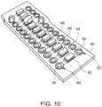
- Fig. 10
- illustrates another printed circuit board for a battery monitoring unit according to the invention.
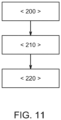
- Fig. 11
- illustrates a flowchart of a process according to the invention for assembling such a battery system.
- Reference will now be made in detail to embodiments, examples of which are illustrated in the accompanying drawings. Effects and features of the exemplary embodiments, and implementation methods thereof will be described with reference to the accompanying drawings. In the drawings, like reference numerals denote like elements, and redundant descriptions are omitted. The present disclosure, however, may be embodied in various different forms, and should not be construed as being limited to only the illustrated embodiments herein. Rather, these embodiments are provided as examples so that this disclosure will be thorough and complete, and will fully convey the aspects and features of the present disclosure to those skilled in the art.
- Accordingly, processes, elements, and techniques that are not considered necessary to those having ordinary skill in the art for a complete understanding of the aspects and features of the present disclosure may not be described. In the drawings, the relative sizes of elements, layers, and regions may be exaggerated for clarity.
- As used herein, the term "and/or" includes any and all combinations of one or more of the associated listed items. Further, the use of "may" when describing embodiments of the present disclosure refers to "one or more embodiments of the present disclosure." In the following description of embodiments of the present disclosure, the terms of a singular form may include plural forms unless the context clearly indicates otherwise.
- It will be understood that although the terms "first" and "second" are used to describe various elements, these elements should not be limited by these terms. These terms are only used to distinguish one element from another element. For example, a first element may be named a second element and, similarly, a second element may be named a first element, without departing from the scope of the present disclosure. Expressions such as "at least one of," when preceding a list of elements, modify the entire list of elements and do not modify the individual elements of the list.
- It will be further understood that the terms "include," "comprise," "including," or "comprising" specify a property, a region, a fixed number, a step, a process, an element, a component, and a combination thereof but do not exclude other properties, regions, fixed numbers, steps, processes, elements, components, and combinations thereof.
- Unless otherwise defined, all terms (including technical and scientific terms) used herein have the same meaning as commonly understood by one of ordinary skill in the art to which the present disclosure belongs. It will be further understood that terms, such as those defined in commonly used dictionaries, should be interpreted as having a meaning that is consistent with their meaning in the context of the relevant art and/or the present specification, and should not be interpreted in an idealized or overly formal sense, unless expressly so defined herein.
- The invention is directed to a battery system including a battery pack and a plurality of battery cells. The battery system further includes a cell monitoring circuit and a conductor arrangement including a plurality of conductor lines, wherein the conductor arrangement includes a flexible flat cable and a plurality of printed circuit boards which overlap with the flexible flat cable, wherein a first end of the conductor lines is connected to the cell monitoring circuit via the flexible flat cable and a second end of the conductor lines is electrically connected to live parts of the battery cells via the printed circuit boards.
- In other words, the invention is related to a battery system with a battery pack including a plurality of battery cells and a unit for electrically connecting those battery cells. The electrically connecting lines connect the cell poles of the battery cells to a battery measurement module. The battery system further includes a battery monitoring system with a conductor arrangement including a plurality of conductor lines, electrically connecting a cell monitoring circuit with the battery cells of the battery pack. The conductor arrangement includes a flexible flat cable as main string and a plurality of printed circuit boards which at least partly overlap with the flexible flat cable. First ends of the conductor lines are connected to the battery cell monitoring circuit via the flexible flat cable. Second ends of the conductor lines are electrically connected to the connection parts of the battery cells via the printed circuit boards.
- The battery system allows a low-cost conductor arrangement to replace more expensive flexible printed circuits for the electrical connection and monitoring of the battery cells. Furthermore, it is possible to use less expensive material and avoid cost extensive materials such as polyimide. The new design allows the usage of much lower cost material for the flexible flat cable instead of current state of the art solutions with flexible printed circuits. The flexible flat cable can be made of straight copper and/or aluminum lines without critical environmental processes. Based on the usage of straight metal lines the design of the electrical connection can be optimized in order to further reduce costs and increase reliability. Furthermore, the proposed battery system allows an easy connection for voltage sensing and temperature sensing and total flexibility for assembly position.
- According to one embodiment, the conductor lines are routed along the flexible flat cable and branched into the plurality of printed circuit boards. This enables particularly simple assembly and particularly simple contacting of the battery cells.
- In an embodiment of the invention, the flexible flat cable includes portions of the conductor lines which are routed through and fixed to the openings of the printed circuit boards in an electrically conduction manner. This ensures a particularly stable and reliable fastening of the conductor lines to the printed circuit boards.
- For example, the portions of the conductor lines which are routed through and fixed to the openings of the printed circuit boards are soldered to the openings of the printed circuit boards. This further improves the connection between the conductor lines and the printed circuit boards.
- According to an embodiment of the invention, the flexible flat cable and/or the printed circuit board includes at least one stability enhancing element which is routed through and fixed to the openings of the printed circuit boards. By a stability enhancing element, the bending stiffness of the flexible flat cable can be improved, reducing the risk of the corresponding conductor snapping off. Furthermore, the assembly process can be eased by such a stability enhancing conductor to facilitate the electrical contacting of the battery cells of the battery pack.
- For example, the stability enhancing element is isolated from the cell monitoring circuit by at least one cut out which interrupts the stability enhancing conductor. This reduces the risk of electrical short circuits.
- According to another embodiment of the battery system, all printed circuit boards connecting the flexible flat cable with the live parts of the battery cells are identical. By using identical printed circuit boards, the variety of parts and the associated costs can be reduced. In addition, the use of identical components can reduce assembly costs and avoid the use of wrong parts.
- In an embodiment of the invention all printed circuit boards including one of the temperature sensors are identical. By using identical printed circuit boards for the connection or integration of the temperature sensors, the variety of parts and the associated costs can be reduced. In addition, the use of identical components can reduce assembly costs and avoid the use of wrong parts.
- According to another embodiment of the invention, at least one of the printed circuit boards connecting the flexible flat cable with one of the live parts of the battery cells includes a fuse. By integrating a fuse into the printed circuit board, the number of components can be reduced when assembling the battery system. This can reduce the work steps and thus the costs in the assembly process.
- For example, all printed circuit boards connecting the flexible flat cable with the live parts of the battery cells include fuses.
- In another embodiment of the invention, the conductor arrangement includes an additional printed circuit board with a plurality of fuses connected between the flexible flat cable and the cell monitoring circuit.
- According to another embodiment, there is provided a cell monitoring unit including a cell monitoring circuit and a conductor arrangement including a plurality of conductor lines. The conductor arrangement includes a flexible flat cable and a plurality of printed circuit boards which at least partly overlap with the flexible flat cable, wherein a first end of the conductor lines is connected to the cell monitoring circuit via the flexible flat cable and a second end of the conductor lines is electrically connected to live parts of the battery cells via the printed circuit boards and/or to at least one temperature sensor included by one of the printed circuit boards.
- Yet another aspect of the invention is related to an electric vehicle including a battery system as described in the above-mentioned paragraphs.
- According to another aspect of the invention, it is provided a method for assembling a battery system, wherein the method includes the following steps of:
- a) providing a battery system as described in the above-mentioned paragraphs
- b) connecting a first end of the conductor lines to the cell monitoring circuit via the flexible flat cable, and
- c) connecting a second end of the conductor lines to live parts of the battery cell via the printed circuit boards and/or to at least one temperature sensor included by one of the printed circuit boards.
-
-
Fig. 1 is a schematic view illustrating abattery system 100 with abattery pack 10 and abattery monitoring unit 50 according to an embodiment of the invention. Thebattery monitoring unit 50 includes acell monitoring circuit 14 and aconductor arrangement 16 including a plurality of conductor lines 18. Theconductor arrangement 16 includes a flexibleflat cable 20 and a plurality of printedcircuit boards 22 which overlap with the flexibleflat cable 20. A first end (or first side) 24 of the conductor lines 18 is connected to thecell monitoring circuit 14 via the flexibleflat cable 20. A second end (or second side) 26 of the conductor lines 18 is connected to liveparts 28 such ascell poles 60 of thebattery cells 12 via the printedcircuit board 22. Thebattery pack 10 as shown inFig. 1 includes ahousing 70 and a plurality ofbattery cells 12 arranged in afirst battery stack 66 and asecond battery stack 68 within thehousing 70. -
Fig.2 discloses abattery monitoring unit 50 according to prior art. Thebattery monitoring unit 50 includes a plurality of flexible printedcircuits 52 which are connected to acircuit board 54 of thebattery monitoring unit 50. Thebattery monitoring unit 50 according to prior art is good and reliable, but expensive and over engineered in terms of the materials used. For example, in the flexible printedcircuits 52 expensive material such as PI (polyimide) is used, which is an overshoot in parameters like voltage resistance, insulation resistance and temperature resistance as well. Based on flexible printedcircuit 52 technology additional material for the production is required which has to be scraped after final production (lot of material loss). -
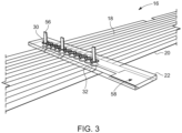
Fig.3 discloses aconductor arrangement 16 according to an embodiment of the invention. Theconductor arrangement 16 includes a flexibleflat cable 20 with a plurality of conduction lines 18. The flexibleflat cable 20 includes a plurality ofpins 56 for connectingopenings 30 of a printedcircuit boards 22 to the conductor lines 18. Thepins 56 are routed along the flexibleflat cable 20 and branched into the plurality of the printedcircuit boards 22. As shown inFig. 3 , the flexibleflat cable 20 includespins 56, that are routed through theopenings 30 of the printedcircuit boards 22 and fixed to theopenings 30 of the printedcircuit boards 22 in an electrically conductive manner. For example, thepins 56 of the conductor lines 18 of the flexibleflat cable 20 are soldered to theopenings 30 of the printedcircuit boards 22. The new solution allows the usage of much lower cost material flexibleflat cable 20 instead of current state of art solution flexible printedcircuits 52. The flexibleflat cable 20 is made out of straight copper oraluminum conductor lines 18 without critical environmental processes. This ends in a better material usage compared to flexible printedcircuits 52. Based on thisstraight conductor lines 18 the design is adopted to enable the flexibleflat cable 20 and printedcircuit boards 22 concept of theconductor arrangement 16. The printedcircuit board 22 further includes awelding surface 58 for connecting the printedcircuit board 22 to liveparts 28 of abattery cell 12. -
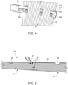
Fig.4 discloses a printedcircuit board 22 that is connected to the flexibleflat cable 20 viapins 56 of the flexibleflat cable 20 andopenings 30 in the printedcircuit board 22. The printedcircuit board 22 further includes afuse 38, for example, SMD type fuse. -
Fig.5 discloses another view of aconductor arrangement 16 including a flexibleflat cable 20 and a printedcircuit board 22 electrically connected to the flexibleflat cable 20. The flexibleflat cable 20 further includes cutouts 34 to prevent contact between thepins 56 and thecell poles 60 of thebattery cells 12. -
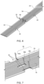
Fig. 6 discloses a flexibleflat cable 20 with a plurality ofcut outs 34. The flexibleflat cable 20 includes threecut outs 34 for thepins 56 and four additional cut outs before and after thepins 56 to avoid potential short cut between thepins 56. -
Fig. 7 shows an enlarge view of the section of the flexibleflat cable 20 as shown inFig. 6 . The flexibleflat cable 20 has threepins 56 cut out and bend 90 degree to be available for soldering to the printedcircuit board 22. First and thelast pins circuit board 22 andmiddle contact pin 56b used to connect to thewelding surface 58 and to thecell pole 60 of thebattery cell 12. -
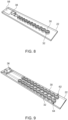
Fig. 8 shows a printedcircuit board 22 of the above embodiment of the invention. The printedcircuit board 22 is designed to be used at any point and have contact to thecell pole 60 through thewelding surface 58 or plated copper and thefuse 38 as predesigned break point in case of unintended short cut. This printedcircuit board 22 is small and universal, that is why it could be produced in large quantity and that is why it will be very cheap and low-cost component. - Instead of one middle contact pin, two pins could be cut out and bent to create a connection for a temperature sensor.
Fig. 9 discloses an alternative example of a printedcircuit board 22. The printedcircuit board 22 includes tworows openings 30 withstability enhancing elements 32 and atemperature sensor 36 is provided on the printedcircuit board 22. A first pin (not shown) of the flexibleflat cable 20 is connected to thefirst row 62 and a second pin (not shown) is connected to thesecond row 64, so that the flexibleflat cable 20 is connected to thelive parts 28 of thebattery cell 12 via thetemperature sensor 36. - One big advantage of the above small universal printed
circuit boards 22 is, that voltage sensing and or temperature sensing is connected in the same way and total flexible for assembly position. -
Fig. 10 discloses an additional printedcircuit board 40 including a plurality offuses circuit board 40 may be used to have all thefuses circuit board 40, so that the other printed circuit boards can be executed without further fuses. The printedcircuit board 40 includes afirst row 62 and asecond row 64 of contact elements withopenings 30 for electrically connecting the printedcircuit board 40 to the flexibleflat cable 20, wherein thefuses first row 62 and thesecond row 64 of contact elements. -
Fig. 11 discloses a flowchart of a process according to the invention for assembling thebattery system 100 according to the invention. In a first step <200>, the battery system as described in the previous sections is provided. In a second step <210>, thefirst end 24 of the conductor lines 18 is connected to thecell monitoring circuit 14 via the flexibleflat cable 20. In a third step <220>, thesecond end 26 of the conductor lines 18 is connected to liveparts 28 of thebattery cells 12 via the printedcircuit boards 22. This allows an easy assembling process for thebattery system 100 and an easy installment of thebattery monitoring unit 50, as the printedcircuit boards 22 can easily be connected to liveparts 28 of the battery cells such ascell poles 60. - Reference signs
- 10
- battery pack
- 12
- battery cell
- 14
- cell monitoring circuit
- 16
- conductor arrangement
- 18
- conductor lines
- 20
- flexible flat cable
- 22
- printed circuit board
- 24
- first end
- 26
- second end
- 28
- live parts
- 30
- opening
- 32
- stability enhancing element
- 34
- cut out
- 36
- temperature sensor
- 38
- fuse
- 40
- printed circuit board
- 42
- fuse
- 44
- fuse
- 46
- fuse
- 48
- fuse
- 50
- battery monitoring unit
- 52
- flexible printed circuit
- 54
- circuit board
- 56
- pin
- 58
- welding surface
- 60
- cell pole
- 62
- first row
- 64
- second row
- 66
- first battery stack
- 68
- second battery stack
- 70
- housing
- 100
- battery system
Claims (14)
- A battery system (100), comprising:
a battery pack (10) comprising a plurality of battery cells (12); a cell monitoring circuit (14) and a conductor arrangement (16) comprising a plurality of conductor lines (18), wherein the conductor arrangement (16) comprises a flexible flat cable (20) and a plurality of printed circuit boards (22) which overlap with the flexible flat cable (20), wherein a first end (24) of the conductor lines (18) is connected to the cell monitoring circuit (14) via the flexible flat cable (20) and a second end (26) of the conductor lines (18) is electrically connected to live parts (28) of the battery cells (12) via the printed circuit boards (22). - The battery system (100) according to claim 1, wherein the conductor lines (18) are routed along the flexible flat cable (20) and branched into the plurality of printed circuit boards (22).
- The battery system (100) according to claim 1 or 2, wherein the flexible flat cable (20) comprises portions of the conductor lines (18) which are routed through and fixed to openings (30) of the printed circuit boards (22) in an electrically conduction manner.
- The battery system (100) according to claim 3, wherein the portions of the conductor lines (18) which are routed through and fixed to the openings (30) of the printed circuit boards (22) are soldered to the openings (30) of the printed circuit boards (22).
- The battery system (100) according to any of the preceding claims, wherein the flexible flat cable (20) and/or the printed circuit board (22) comprises at least one stability enhancing element (32) which is routed through and fixed to the openings (30) of the printed circuit boards (22).
- The battery system (100) according to claim 5, wherein the stability enhancing element (32) is isolated from the cell monitoring circuit (14) by at least one cut out (34) which interrupts the stability enhancing conductor (32).
- The battery system (100) according to any of the preceding claims, wherein all printed circuit boards (22) connecting the flexible flat cable (20) with the live parts (28) are identical.
- The battery system (100) according to any of the preceding claims, wherein a plurality of printed circuit boards (22) comprises a temperature sensor (36) and all printed circuit boards (22) comprising one of the temperature sensors (36) are identical.
- The battery system (100) according to any of the preceding claims, wherein at least one of the printed circuit boards (22) connecting the flexible flat cable (20) with one of the live parts (28) comprises a fuse (38).
- The battery system (100) according to any of the preceding claims, wherein the at least one of the printed circuit boards (22) comprises a temperature sensor (36) and the conductor line (18) is electrically connected to live parts (28) of a battery cell (12) via the temperature sensor (36).
- The battery system (100) according to any of the preceding claims, wherein the conductor arrangement (16) comprises an additional printed circuit board (40) with a plurality of fuses (42, 44, 46, 48) connected between the flexible flat cable (20) and the cell monitoring circuit (14).
- A battery monitoring unit (50) comprising a cell monitoring circuit (14) and a conductor arrangement (16) comprising a plurality of conductor lines (18), wherein the conductor arrangement (16) comprises a flexible flat cable (20) and a plurality of printed circuit boards (22) which overlap with the flexible flat cable (20), wherein a first end (24) of the conductor lines (18) is connected to the cell monitoring circuit (14) via the flexible flat cable (20) and a second end (26) of the conductor lines (18) is electrically connectable to live parts (28) of the battery cells (12) via the printed circuit boards (22).
- An electric vehicle comprising the battery system (100) according to anyone of claims 1 through 11.
- A method for assembling a battery system (100), wherein the method comprises the steps of:a) providing a battery system (100) as defined in claim 1;b) connecting a first end (24) of the conductor lines (18) to the cell monitoring circuit (14) via the flexible flat cable (20),c) connecting a second end (26) of the conductor lines (18) to live parts (28) of the battery cells (12) via the printed circuit boards (22).
Priority Applications (5)
| Application Number | Priority Date | Filing Date | Title |
|---|---|---|---|
| EP23193423.3A EP4513615B1 (en) | 2023-08-25 | 2023-08-25 | Battery system and method of assembling a battery system |
| US18/747,051 US20250070401A1 (en) | 2023-08-25 | 2024-06-18 | Battery system and method of assembling a battery system |
| KR1020240112287A KR20250031138A (en) | 2023-08-25 | 2024-08-21 | Battery system and method of assembling a battery system |
| CN202411157028.6A CN119725826A (en) | 2023-08-25 | 2024-08-22 | Battery system and method of assembling a battery system |
| CN202422040124.4U CN223401670U (en) | 2023-08-25 | 2024-08-22 | Battery system, electric vehicle and battery monitoring unit |
Applications Claiming Priority (1)
| Application Number | Priority Date | Filing Date | Title |
|---|---|---|---|
| EP23193423.3A EP4513615B1 (en) | 2023-08-25 | 2023-08-25 | Battery system and method of assembling a battery system |
Publications (2)
| Publication Number | Publication Date |
|---|---|
| EP4513615A1 true EP4513615A1 (en) | 2025-02-26 |
| EP4513615B1 EP4513615B1 (en) | 2026-05-06 |
Family
ID=87845484
Family Applications (1)
| Application Number | Title | Priority Date | Filing Date |
|---|---|---|---|
| EP23193423.3A Active EP4513615B1 (en) | 2023-08-25 | 2023-08-25 | Battery system and method of assembling a battery system |
Country Status (4)
| Country | Link |
|---|---|
| US (1) | US20250070401A1 (en) |
| EP (1) | EP4513615B1 (en) |
| KR (1) | KR20250031138A (en) |
| CN (2) | CN119725826A (en) |
Citations (4)
| Publication number | Priority date | Publication date | Assignee | Title |
|---|---|---|---|---|
| CN216085214U (en) * | 2021-09-18 | 2022-03-18 | 中航锂电科技有限公司 | Signal acquisition wire harness assembly and battery device |
| CN216488417U (en) | 2021-08-24 | 2022-05-10 | 湖北亿纬动力有限公司 | FFC and plastic sucking disc integrated CCS's collection structure and battery module |
| CN115149221A (en) * | 2022-05-17 | 2022-10-04 | 常州长盈精密技术有限公司 | Battery pack wire harness for vehicle |
| CN218334041U (en) | 2022-05-17 | 2023-01-17 | 常州长盈精密技术有限公司 | Battery pack wire harness for vehicle |
-
2023
- 2023-08-25 EP EP23193423.3A patent/EP4513615B1/en active Active
-
2024
- 2024-06-18 US US18/747,051 patent/US20250070401A1/en active Pending
- 2024-08-21 KR KR1020240112287A patent/KR20250031138A/en active Pending
- 2024-08-22 CN CN202411157028.6A patent/CN119725826A/en active Pending
- 2024-08-22 CN CN202422040124.4U patent/CN223401670U/en active Active
Patent Citations (4)
| Publication number | Priority date | Publication date | Assignee | Title |
|---|---|---|---|---|
| CN216488417U (en) | 2021-08-24 | 2022-05-10 | 湖北亿纬动力有限公司 | FFC and plastic sucking disc integrated CCS's collection structure and battery module |
| CN216085214U (en) * | 2021-09-18 | 2022-03-18 | 中航锂电科技有限公司 | Signal acquisition wire harness assembly and battery device |
| CN115149221A (en) * | 2022-05-17 | 2022-10-04 | 常州长盈精密技术有限公司 | Battery pack wire harness for vehicle |
| CN218334041U (en) | 2022-05-17 | 2023-01-17 | 常州长盈精密技术有限公司 | Battery pack wire harness for vehicle |
Also Published As
| Publication number | Publication date |
|---|---|
| KR20250031138A (en) | 2025-03-06 |
| CN223401670U (en) | 2025-09-30 |
| CN119725826A (en) | 2025-03-28 |
| EP4513615B1 (en) | 2026-05-06 |
| US20250070401A1 (en) | 2025-02-27 |
Similar Documents
| Publication | Publication Date | Title |
|---|---|---|
| EP3965207B1 (en) | Battery system with advanced battery disconnecting unit | |
| US11682797B2 (en) | Systems and methods for providing individual battery cell circuit protection | |
| US12362445B2 (en) | Battery system with advanced battery disconnecting unit | |
| US11801753B2 (en) | Battery system and vehicle including the battery system | |
| EP2612389B1 (en) | High-voltage battery with integrated cell connector | |
| EP4047713A1 (en) | Thermal protection of connector | |
| EP4379920A1 (en) | Battery system and method of assembling thereof | |
| US12113380B2 (en) | Pre-charge unit for charging a dc link capacitor and battery system including the same | |
| US12609423B2 (en) | Relay control system and battery system | |
| EP4089790B1 (en) | Battery cell and battery system comprising a battery cell | |
| EP4060785B1 (en) | Battery system and vehicle including the battery system | |
| US11900785B2 (en) | Thermal protection of connector | |
| EP4156371A1 (en) | Battery system comprising cylindrical cells and a temperature sensor and method of installing the same | |
| US20250266629A1 (en) | Method for electrically connecting electronic components of a battery system and battery system | |
| EP4513615B1 (en) | Battery system and method of assembling a battery system | |
| US12614772B2 (en) | Battery system comprising cylindrical cells and a temperature sensor and method of installing the same | |
| EP4170790B1 (en) | Battery system comprising cylindrical cells and a temperature sensor and method of installing the same | |
| US20230318050A1 (en) | Battery pack, an electric vehicle and a method for assembling a battery pack | |
| EP4557450A1 (en) | Battery module | |
| US12580233B2 (en) | Battery system and method for operating the same | |
| EP4254623A1 (en) | A battery pack, an electric vehicle and a method for assembling a battery pack | |
| EP3944454A1 (en) | Pre-charge unit for charging a dc link capacitor and battery system comprising the same | |
| CN223927602U (en) | Battery module and battery pack including the same | |
| EP4186746A1 (en) | Battery system and method for operating the same | |
| EP4124498A1 (en) | Relay control system and battery system |
Legal Events
| Date | Code | Title | Description |
|---|---|---|---|
| PUAI | Public reference made under article 153(3) epc to a published international application that has entered the european phase |
Free format text: ORIGINAL CODE: 0009012 |
|
| STAA | Information on the status of an ep patent application or granted ep patent |
Free format text: STATUS: REQUEST FOR EXAMINATION WAS MADE |
|
| 17P | Request for examination filed |
Effective date: 20240816 |
|
| AK | Designated contracting states |
Kind code of ref document: A1 Designated state(s): AL AT BE BG CH CY CZ DE DK EE ES FI FR GB GR HR HU IE IS IT LI LT LU LV MC ME MK MT NL NO PL PT RO RS SE SI SK SM TR |
|
| GRAP | Despatch of communication of intention to grant a patent |
Free format text: ORIGINAL CODE: EPIDOSNIGR1 |
|
| STAA | Information on the status of an ep patent application or granted ep patent |
Free format text: STATUS: GRANT OF PATENT IS INTENDED |
|
| RIC1 | Information provided on ipc code assigned before grant |
Ipc: H01M 10/42 20060101AFI20251216BHEP Ipc: H01M 10/48 20060101ALI20251216BHEP Ipc: H01M 50/519 20210101ALI20251216BHEP Ipc: H01M 50/569 20210101ALI20251216BHEP Ipc: H01M 50/583 20210101ALI20251216BHEP |
|
| INTG | Intention to grant announced |
Effective date: 20260105 |
|
| GRAS | Grant fee paid |
Free format text: ORIGINAL CODE: EPIDOSNIGR3 |
|
| GRAA | (expected) grant |
Free format text: ORIGINAL CODE: 0009210 |
|
| STAA | Information on the status of an ep patent application or granted ep patent |
Free format text: STATUS: THE PATENT HAS BEEN GRANTED |