EP4513536A2 - Substrate processing apparatus, method of processing substrate, method of manufacturing semiconductor device, program, and control apparatus - Google Patents
Substrate processing apparatus, method of processing substrate, method of manufacturing semiconductor device, program, and control apparatus Download PDFInfo
- Publication number
- EP4513536A2 EP4513536A2 EP24196145.7A EP24196145A EP4513536A2 EP 4513536 A2 EP4513536 A2 EP 4513536A2 EP 24196145 A EP24196145 A EP 24196145A EP 4513536 A2 EP4513536 A2 EP 4513536A2
- Authority
- EP
- European Patent Office
- Prior art keywords
- screen
- information
- substrate processing
- processing apparatus
- displaying
- Prior art date
- Legal status (The legal status is an assumption and is not a legal conclusion. Google has not performed a legal analysis and makes no representation as to the accuracy of the status listed.)
- Pending
Links
Images


Classifications
-
- H—ELECTRICITY
- H10—SEMICONDUCTOR DEVICES; ELECTRIC SOLID-STATE DEVICES NOT OTHERWISE PROVIDED FOR
- H10P—GENERIC PROCESSES OR APPARATUS FOR THE MANUFACTURE OR TREATMENT OF DEVICES COVERED BY CLASS H10
- H10P72/00—Handling or holding of wafers, substrates or devices during manufacture or treatment thereof
- H10P72/06—Apparatus for monitoring, sorting, marking, testing or measuring
- H10P72/0604—Process monitoring, e.g. flow or thickness monitoring
-
- H—ELECTRICITY
- H10—SEMICONDUCTOR DEVICES; ELECTRIC SOLID-STATE DEVICES NOT OTHERWISE PROVIDED FOR
- H10P—GENERIC PROCESSES OR APPARATUS FOR THE MANUFACTURE OR TREATMENT OF DEVICES COVERED BY CLASS H10
- H10P72/00—Handling or holding of wafers, substrates or devices during manufacture or treatment thereof
- H10P72/30—Handling or holding of wafers, substrates or devices during manufacture or treatment thereof for conveying, e.g. between different workstations
- H10P72/32—Handling or holding of wafers, substrates or devices during manufacture or treatment thereof for conveying, e.g. between different workstations between different workstations
- H10P72/3218—Conveying cassettes, containers or carriers
-
- G—PHYSICS
- G05—CONTROLLING; REGULATING
- G05B—CONTROL OR REGULATING SYSTEMS IN GENERAL; FUNCTIONAL ELEMENTS OF SUCH SYSTEMS; MONITORING OR TESTING ARRANGEMENTS FOR SUCH SYSTEMS OR ELEMENTS
- G05B19/00—Program-control systems
- G05B19/02—Program-control systems electric
- G05B19/418—Total factory control, i.e. centrally controlling a plurality of machines, e.g. direct or distributed numerical control [DNC], flexible manufacturing systems [FMS], integrated manufacturing systems [IMS] or computer integrated manufacturing [CIM]
-
- G—PHYSICS
- G06—COMPUTING OR CALCULATING; COUNTING
- G06F—ELECTRIC DIGITAL DATA PROCESSING
- G06F3/00—Input arrangements for transferring data to be processed into a form capable of being handled by the computer; Output arrangements for transferring data from processing unit to output unit, e.g. interface arrangements
- G06F3/14—Digital output to display device ; Cooperation and interconnection of the display device with other functional units
- G06F3/147—Digital output to display device ; Cooperation and interconnection of the display device with other functional units using display panels
-
- G—PHYSICS
- G05—CONTROLLING; REGULATING
- G05B—CONTROL OR REGULATING SYSTEMS IN GENERAL; FUNCTIONAL ELEMENTS OF SUCH SYSTEMS; MONITORING OR TESTING ARRANGEMENTS FOR SUCH SYSTEMS OR ELEMENTS
- G05B23/00—Testing or monitoring of control systems or parts thereof
- G05B23/02—Electric testing or monitoring
- G05B23/0205—Electric testing or monitoring by means of a monitoring system capable of detecting and responding to faults
- G05B23/0208—Electric testing or monitoring by means of a monitoring system capable of detecting and responding to faults characterized by the configuration of the monitoring system
- G05B23/0216—Human interface functionality, e.g. monitoring system providing help to the user in the selection of tests or in its configuration
-
- G—PHYSICS
- G05—CONTROLLING; REGULATING
- G05B—CONTROL OR REGULATING SYSTEMS IN GENERAL; FUNCTIONAL ELEMENTS OF SUCH SYSTEMS; MONITORING OR TESTING ARRANGEMENTS FOR SUCH SYSTEMS OR ELEMENTS
- G05B23/00—Testing or monitoring of control systems or parts thereof
- G05B23/02—Electric testing or monitoring
- G05B23/0205—Electric testing or monitoring by means of a monitoring system capable of detecting and responding to faults
- G05B23/0259—Electric testing or monitoring by means of a monitoring system capable of detecting and responding to faults characterized by the response to fault detection
- G05B23/0267—Fault communication, e.g. human machine interface [HMI]
- G05B23/027—Alarm generation, e.g. communication protocol; Forms of alarm
-
- G—PHYSICS
- G06—COMPUTING OR CALCULATING; COUNTING
- G06F—ELECTRIC DIGITAL DATA PROCESSING
- G06F3/00—Input arrangements for transferring data to be processed into a form capable of being handled by the computer; Output arrangements for transferring data from processing unit to output unit, e.g. interface arrangements
- G06F3/01—Input arrangements or combined input and output arrangements for interaction between user and computer
- G06F3/048—Interaction techniques based on graphical user interfaces [GUI]
-
- G—PHYSICS
- G06—COMPUTING OR CALCULATING; COUNTING
- G06F—ELECTRIC DIGITAL DATA PROCESSING
- G06F3/00—Input arrangements for transferring data to be processed into a form capable of being handled by the computer; Output arrangements for transferring data from processing unit to output unit, e.g. interface arrangements
- G06F3/01—Input arrangements or combined input and output arrangements for interaction between user and computer
- G06F3/048—Interaction techniques based on graphical user interfaces [GUI]
- G06F3/0484—Interaction techniques based on graphical user interfaces [GUI] for the control of specific functions or operations, e.g. selecting or manipulating an object, an image or a displayed text element, setting a parameter value or selecting a range
- G06F3/04845—Interaction techniques based on graphical user interfaces [GUI] for the control of specific functions or operations, e.g. selecting or manipulating an object, an image or a displayed text element, setting a parameter value or selecting a range for image manipulation, e.g. dragging, rotation, expansion or change of colour
-
- G—PHYSICS
- G06—COMPUTING OR CALCULATING; COUNTING
- G06F—ELECTRIC DIGITAL DATA PROCESSING
- G06F3/00—Input arrangements for transferring data to be processed into a form capable of being handled by the computer; Output arrangements for transferring data from processing unit to output unit, e.g. interface arrangements
- G06F3/01—Input arrangements or combined input and output arrangements for interaction between user and computer
- G06F3/048—Interaction techniques based on graphical user interfaces [GUI]
- G06F3/0487—Interaction techniques based on graphical user interfaces [GUI] using specific features provided by the input device, e.g. functions controlled by the rotation of a mouse with dual sensing arrangements, or of the nature of the input device, e.g. tap gestures based on pressure sensed by a digitiser
- G06F3/0488—Interaction techniques based on graphical user interfaces [GUI] using specific features provided by the input device, e.g. functions controlled by the rotation of a mouse with dual sensing arrangements, or of the nature of the input device, e.g. tap gestures based on pressure sensed by a digitiser using a touch-screen or digitiser, e.g. input of commands through traced gestures
- G06F3/04886—Interaction techniques based on graphical user interfaces [GUI] using specific features provided by the input device, e.g. functions controlled by the rotation of a mouse with dual sensing arrangements, or of the nature of the input device, e.g. tap gestures based on pressure sensed by a digitiser using a touch-screen or digitiser, e.g. input of commands through traced gestures by partitioning the display area of the touch-screen or the surface of the digitising tablet into independently controllable areas, e.g. virtual keyboards or menus
-
- H—ELECTRICITY
- H10—SEMICONDUCTOR DEVICES; ELECTRIC SOLID-STATE DEVICES NOT OTHERWISE PROVIDED FOR
- H10P—GENERIC PROCESSES OR APPARATUS FOR THE MANUFACTURE OR TREATMENT OF DEVICES COVERED BY CLASS H10
- H10P72/00—Handling or holding of wafers, substrates or devices during manufacture or treatment thereof
- H10P72/30—Handling or holding of wafers, substrates or devices during manufacture or treatment thereof for conveying, e.g. between different workstations
- H10P72/32—Handling or holding of wafers, substrates or devices during manufacture or treatment thereof for conveying, e.g. between different workstations between different workstations
- H10P72/3222—Loading to or unloading from a conveyor
-
- H—ELECTRICITY
- H10—SEMICONDUCTOR DEVICES; ELECTRIC SOLID-STATE DEVICES NOT OTHERWISE PROVIDED FOR
- H10P—GENERIC PROCESSES OR APPARATUS FOR THE MANUFACTURE OR TREATMENT OF DEVICES COVERED BY CLASS H10
- H10P72/00—Handling or holding of wafers, substrates or devices during manufacture or treatment thereof
- H10P72/30—Handling or holding of wafers, substrates or devices during manufacture or treatment thereof for conveying, e.g. between different workstations
- H10P72/33—Handling or holding of wafers, substrates or devices during manufacture or treatment thereof for conveying, e.g. between different workstations into and out of processing chamber
- H10P72/3304—Handling or holding of wafers, substrates or devices during manufacture or treatment thereof for conveying, e.g. between different workstations into and out of processing chamber characterised by movements or sequence of movements of transfer devices
-
- H—ELECTRICITY
- H10—SEMICONDUCTOR DEVICES; ELECTRIC SOLID-STATE DEVICES NOT OTHERWISE PROVIDED FOR
- H10P—GENERIC PROCESSES OR APPARATUS FOR THE MANUFACTURE OR TREATMENT OF DEVICES COVERED BY CLASS H10
- H10P72/00—Handling or holding of wafers, substrates or devices during manufacture or treatment thereof
- H10P72/30—Handling or holding of wafers, substrates or devices during manufacture or treatment thereof for conveying, e.g. between different workstations
- H10P72/34—Handling or holding of wafers, substrates or devices during manufacture or treatment thereof for conveying, e.g. between different workstations the wafers being stored in a carrier, involving loading and unloading
- H10P72/3404—Storage means
-
- H—ELECTRICITY
- H10—SEMICONDUCTOR DEVICES; ELECTRIC SOLID-STATE DEVICES NOT OTHERWISE PROVIDED FOR
- H10P—GENERIC PROCESSES OR APPARATUS FOR THE MANUFACTURE OR TREATMENT OF DEVICES COVERED BY CLASS H10
- H10P95/00—Generic processes or apparatus for manufacture or treatments not covered by the other groups of this subclass
-
- G—PHYSICS
- G05—CONTROLLING; REGULATING
- G05B—CONTROL OR REGULATING SYSTEMS IN GENERAL; FUNCTIONAL ELEMENTS OF SUCH SYSTEMS; MONITORING OR TESTING ARRANGEMENTS FOR SUCH SYSTEMS OR ELEMENTS
- G05B2219/00—Program-control systems
- G05B2219/20—Pc systems
- G05B2219/24—Pc safety
- G05B2219/24103—Graphical display of proces as function of detected alarm signals
-
- G—PHYSICS
- G06—COMPUTING OR CALCULATING; COUNTING
- G06F—ELECTRIC DIGITAL DATA PROCESSING
- G06F2203/00—Indexing scheme relating to G06F3/00 - G06F3/048
- G06F2203/048—Indexing scheme relating to G06F3/048
- G06F2203/04803—Split screen, i.e. subdividing the display area or the window area into separate subareas
-
- H—ELECTRICITY
- H10—SEMICONDUCTOR DEVICES; ELECTRIC SOLID-STATE DEVICES NOT OTHERWISE PROVIDED FOR
- H10P—GENERIC PROCESSES OR APPARATUS FOR THE MANUFACTURE OR TREATMENT OF DEVICES COVERED BY CLASS H10
- H10P72/00—Handling or holding of wafers, substrates or devices during manufacture or treatment thereof
- H10P72/04—Apparatus for manufacture or treatment
-
- Y—GENERAL TAGGING OF NEW TECHNOLOGICAL DEVELOPMENTS; GENERAL TAGGING OF CROSS-SECTIONAL TECHNOLOGIES SPANNING OVER SEVERAL SECTIONS OF THE IPC; TECHNICAL SUBJECTS COVERED BY FORMER USPC CROSS-REFERENCE ART COLLECTIONS [XRACs] AND DIGESTS
- Y02—TECHNOLOGIES OR APPLICATIONS FOR MITIGATION OR ADAPTATION AGAINST CLIMATE CHANGE
- Y02P—CLIMATE CHANGE MITIGATION TECHNOLOGIES IN THE PRODUCTION OR PROCESSING OF GOODS
- Y02P90/00—Enabling technologies with a potential contribution to greenhouse gas [GHG] emissions mitigation
- Y02P90/02—Total factory control, e.g. smart factories, flexible manufacturing systems [FMS] or integrated manufacturing systems [IMS]
Definitions
- the present disclosure relates to a substrate processing apparatus, a substrate processing method, a method of manufacturing a semiconductor device, a program, and a control apparatus.
- a substrate processing apparatus capable of displaying an operable sub-screen superimposed on a main screen that displays apparatus information used in the substrate processing apparatus.
- Some embodiments of the present disclosure provide a technique capable of improving an efficiency of operations on a main screen where apparatus information used in a substrate processing apparatus may be displayed or operated.
- a technique that includes a controller configured to be capable of operating a first screen capable of displaying or operating apparatus information that is used in a substrate processing apparatus while at least one second screen capable of displaying at least one piece of related information which is related to the apparatus information is displayed on the first screen.
- FIGS. 1 to 10 the drawings used in the following description are schematic, and dimensional relationships, ratios, and the like of the respective components illustrated in the drawings may not match actual ones. Further, dimensional relationships, ratios, and the like of the respective components among plural drawings may not match one another. Further, the present disclosure is not limited to the following embodiments in any way, and modifications may be made within the scope of the present disclosure as appropriate.
- FIG. 1 is a perspective view schematically illustrating an example of a substrate processing apparatus 2 according to the embodiments of the present disclosure.
- the substrate processing apparatus 2 includes a cassette 100, which accommodates a plurality of substrates 200 made of, e.g., silicon, and a housing 101.
- a cassette stage 105 which serves as a substrate container delivery stage, is installed inside the housing 101 at a cassette loading/unloading port (not illustrated).
- the cassette 100 is configured to be loaded onto the cassette stage 105 and to be unloaded from the cassette stage 105 by an in-process transporter (not illustrated).
- a cassette shelf 109 which serves as a substrate container mounting shelf, is installed approximately at the center of the housing 101 in a front-rear direction.
- the cassette shelf 109 is configured to store a plurality of cassettes 100 in a plurality of rows and columns.
- the cassette shelf 109 is provided with a carriage shelf 123 where the cassettes 100 are stored.
- a spare cassette shelf 110 is provided above the cassette stage 105 and is configured to temporarily store the cassettes 100.
- a cassette elevator 115 which is a substrate container lifting mechanism configured to be capable of moving up or down while holding the cassettes 100, and a cassette carrier 114 are provided between the cassette stage 105 and the cassette shelf 109.
- the cassette elevator 115 and the cassette carrier 114 are configured to, through continuous operations thereof, transport the cassettes 100 among the cassette stage 105, the cassette shelf 109, and the spare cassette shelf 110.
- a substrate carrier 112 configured to be capable of rotating or linearly driving the substrates 200 in a horizontal direction and a carrier elevator 113 configured to raise or lower the substrate carrier 112 are provided behind the cassette shelf 109.
- the carrier elevator 113 is installed at a right end of the housing 101.
- the carrier elevator 113 and the substrate carrier 112 are configured to, through continuous operations thereof, charge or discharge the substrates 200 into or from a boat 217, which serves as a substrate holder, by using a tweezer 111, which is a substrate holding piece of the substrate carrier 112, as a mounter of the substrates 200.
- a process furnace 202 is provided at a rear upper side of the housing 101.
- a lower end of the process furnace 202 is configured to be opened or closed by a furnace opening shutter 116, which serves as an opening/closing mechanism for a furnace opening.
- a boat elevator 121 which serves as a substrate holder lifting mechanism as a lifting mechanism configured to raise or lower the boat 217 into or from the process furnace 202 is provided below the process furnace 202.
- a seal cap 219 which serves as a lid, is horizontally placed at a lifter 122, which is a connector connected to a lifting stand of the boat elevator 121, such that the seal cap 219 is configured to vertically support the boat 217 and to be capable of closing a lower end of the process furnace 202.
- the boat 217 serving as a substrate holder includes a plurality of boat columns 221, and is configured to horizontally hold a plurality of wafers 200 (e.g., 50 or more and 150 or less substrates) with centers of the substrates 200 aligned with one another in a vertical direction.
- a plurality of wafers 200 e.g., 50 or more and 150 or less substrates
- a cleaner 118 is provided above the cassette shelf 109 and is constituted by a supply fan and a dust-proof filter to supply clean air, which is an atmosphere purified from an external air inflow from a duct 124.
- the cleaner 118 is configured to circulate the clean air to the interior of the housing 101.
- the cassette 100 is loaded from the cassette loading/unloading port.
- the cassette 100 is automatically transported to a designated shelf position on either the cassette shelf 109 or the spare cassette shelf 110, where the cassette 100 is temporarily stored. Thereafter, the cassette 100 is carried from either the cassette shelf 109 or the spare cassette shelf 110 to the carriage shelf 123, or is directly transported to the carriage shelf 123.
- the substrate 200 is picked up from the cassette 100 by the tweezer 111 of the substrate carrier 112 through a substrate entrance, and is charged into the boat 217. After delivering the substrate 200 to the boat 217, the substrate carrier 112 returns to the cassette 100 to charge the next substrate 200 into the boat 217.
- the lower end of the process furnace 202 which was closed by the furnace opening shutter 116, is opened by the furnace opening shutter 116. Subsequently, the boat 217 holding a group of substrates 200 is loaded into the process furnace 202 when the seal cap 219 is raised by the boat elevator 121.
- the substrates 200 are subjected to arbitrary processing in the process furnace 202. After the processing, the substrates 200 and the cassette 100 are unloaded out of the housing 101 in the reverse procedure.
- FIG. 2 is a schematic configuration view of the process furnace 202 in the substrate processing apparatus 2 illustrated in FIG. 1 .
- the process furnace 202 includes a reaction tube 203.
- the reaction tube 203 is made of, for example, a heat-resistant and non-metallic material such as quartz (SiO 2 ) or silicon carbide (SiC), and formed in a cylindrical shape with a closed upper end and an open lower end.
- a process chamber 201 is formed inside the reaction tube 203.
- the boat 217 serving as a substrate holder is inserted from below into the process chamber 201, such that the substrates 200 held in a horizontal posture by the boat 217 are accommodated while being aligned with one another in multiple stages along a vertical direction.
- the boat 217 accommodated in the process chamber 201 is configured to be rotatable in a state where the plurality of substrates 200 are mounted on the boat 217, while maintaining an airtightness of the process chamber 201, when a rotating shaft 44 is rotated by a rotator 43.
- a manifold 45 is arranged concentrically with the reaction tube 203 below the reaction tube 203.
- the manifold 45 is made of, for example, a metallic material such as stainless steel, and is formed in a cylindrical shape with open upper and lower ends.
- the reaction tube 203 is supported in a vertical orientation from the lower end side by the manifold 45.
- the reaction tube 203 forming the process chamber 201 is erected vertically via the manifold 45, thus constituting the process furnace 202.
- a lower end of the manifold 45 is configured to be airtightly sealed by the seal cap 219 when the boat elevator 121 moves up.
- a seal 219a such as an O-ring is provided between the lower end of the manifold 45 and the seal cap 219 to airtightly seal the process chamber 201.
- the manifold 45 is connected to each of a gas introduction pipe 47 configured to introduce, e.g., a precursor gas or a purge gas into the process chamber 201 and an exhaust pipe 48 configured to discharge the gas from the process chamber 201.
- a pressure of the process chamber 201 is controlled while an APC valve 35 is regulated based on detection results of a pressure sensor (not illustrated).
- a heater 207 which serves as a heating mechanism, is arranged concentrically with the reaction tube 203 around an outer periphery of the reaction tube 203.
- the heater 207 is configured to heat the process chamber 201 so that a temperature distribution of the entire process chamber 201 becomes a uniform or predetermined temperature distribution.
- the substrate processing apparatus 2 includes a control apparatus 10 serving as a main controller, and the control apparatus 10 controls the substrate processing apparatus 2.
- the control apparatus 10 may be built into the substrate processing apparatus 2 or may be installed in an accessible manner outside the substrate processing apparatus 2.
- the control apparatus 10 controls, e.g., an operation of each component constituting the substrate processing apparatus 2 and the process furnace 202.
- FIG. 3 is a block diagram illustrating an example of a configuration of the control apparatus 10 included in the substrate processing apparatus 2 according to the embodiments.
- the substrate processing apparatus 2 includes the control apparatus 10 serving as a main controller, an external communicator 21, an external memory 22, an operator 23, a display 24, a process controller 25, and a transport controller 26.
- control apparatus 10 includes a controller 11, a memory 14, and an I/O (also referred to as "I/O port") 15.
- the controller 11 includes a central processing unit (CPU) 12 and a random access memory (RAM) 13.
- the control apparatus 10 is connected to the operator 23 and is also connected to the process controller 25 and the transport controller 26 via the I/O 15. Being electrically connected to each of the process controller 25 and the transport controller 26 via the I/O 15, the control apparatus 10 is configured to be capable of performing, e.g., transmission and reception of each data or downloading and uploading of each file.
- the control apparatus 10 is connected to an external host computer (not illustrated) via the external communicator 21. Therefore, even in a case where the substrate processing apparatus 2 is installed in a clean room, the host computer may be located outside the clean room such as in an office. Further, the control apparatus 10 is connected to the external memory 22, which serves as a mount into which a universal serial bus (USB) memory, etc. as an example of a recording medium is detachably inserted.
- USB universal serial bus
- the operator 23 is integrated with the display 24, or is connected to the display 24 via, e.g., a video cable.
- the display 24 is, for example, a liquid crystal display panel.
- the display 24 is configured to display each operation screen configured to operate the substrate processing apparatus 2.
- the operation screen includes a screen configured to monitor statuses of a substrate process system controlled by the process controller 25 and a substrate transport system controlled by the transport controller 26.
- the display 24 may be further provided with each operation button as an input component to input operational instructions for the substrate process system and the substrate transport system.
- the operator 23 enables the display 24 to display information generated in the substrate processing apparatus 2 through the operation screen. Further, the operator 23 enables, for example, the output of the information displayed on the display 24 to a device such as a USB memory inserted into the external memory 22.
- the operator 23 receives input data (input instructions) from the operation screen displayed on the display 24, and transmits the input data to the control apparatus 10. Further, the operator 23 is configured to receive instructions (control instructions) to execute an arbitrary substrate processing recipe (also referred to as "process recipe") among a plurality of recipes stored in the memory 14 or a recipe developed in the RAM 13 and to transmit the instructions to the control apparatus 10.
- the operator 23 and the display 24 may be configured with a touch panel.
- the operator 23 and the display 24 are provided separately from the control apparatus 10 but may be integrally included in the control apparatus 10.
- the process controller 25 although not illustrated herein, includes a temperature controller, a gas flow rate controller, and a pressure controller. Each of the temperature controller, the gas flow rate controller, and the pressure controller constitutes a sub-controller and is electrically connected to the process controller 25, enabling transmission and reception of each data, downloading and uploading of each file, or the like.
- the process controller 25 and each sub-controller may be configured separately or integrally.
- the transport controller 26 although not illustrated herein, includes a mechanism controller.
- the mechanism controller is configured to control each of a drive system, a rotator system, and a lifting system of the substrate processing apparatus 2.
- the transport controller 26 is configured to control a transport operation of each transport mechanism included in the substrate processing apparatus 2.
- the processing of the substrate 200 is performed, for example, according to a recipe that defines a processing condition for the substrate 200.
- the recipe is stored in the memory 14, and the controller 11 acquires the stored recipe during substrate processing, thus controlling the substrate processing based on the processing condition defined in the recipe.
- the recipe may be stored in the external memory 22 as well as the memory 14. Examples of the external memory 22 include a USB memory, compact disc (CD), digital versatile disc (DVD), and external hard disk. Further, the recipe may be acquired from an external device via the external communicator 21.
- control apparatus 10 the process controller 25, and the transport controller 26 according to the embodiments are not limited to a dedicated system and may be realized by using a conventional computer system.
- each controller configured to execute a predetermined processing may be configured by installing a program for executing the above-described processing from a recording medium (such as CD-ROM or USB) storing that program to a general-purpose computer.
- the programs may be supplied through a predetermined recording medium as described above, or may be supplied through, for example, communication lines, communication networks, and communication systems.
- the control apparatus 10 is constituted as a computer equipped with the CPU 12, RAM 13, memory 14, and I/O 15.
- the memory 14 stores, e.g., each recipe file for recipes that define processing conditions and processing procedures, a control program file for executing each recipe file, a parameter file (setting value file) for setting processing conditions and processing procedures, an error-processing program file, an error-processing parameter file, a file for various screens including an input screen configured to input processing parameters, and a file for various icons (none of which are illustrated).
- the control apparatus 10 is connected to a network such as the Internet, local area network (LAN), or wide area network (WAN) by using the external communicator 21, thus enabling communication with external devices via the network.
- LAN local area network
- WAN wide area network
- the memory 14 may be, for example, a hard disk drive (HDD), solid state drive (SSD), or flash memory.
- the memory 14 stores a screen display processing program for executing a screen display processing according to the embodiments of the present disclosure.
- the screen display processing program may be installed in advance in the substrate processing apparatus 2, for example.
- the screen display processing program may be realized by being recorded on a non-volatile recording medium or being distributed via a network, and appropriately being installed in the substrate processing apparatus 2.
- examples of the non-volatile recording medium include a compact disc read only memory (CD-ROM), magneto-optical disk, HDD, digital versatile disc read only memory (DVD-ROM), flash memory, memory card, and USB.
- the CPU 12 of the substrate processing apparatus 2 functions as a display processor 12A illustrated in FIG. 4 by writing the screen display processing program stored in the memory 14 into the RAM 13 and executing the same.
- FIG. 4 is a block diagram illustrating an example of a functional configuration of the substrate processing apparatus 2 according to the embodiments of the present disclosure.
- the display 24 includes a user interface (UI) 24A and a screen 24B.
- the UI 24A acquires at least a part of information displayed on the screen 24B as image data and transmits the same to the screen 24B. Further, the UI 24A receives inputs from the user and processes the same.
- the screen 24B presents the image data transmitted from the UI 24A to the user.
- the display 24 may display a first screen and at least one second screen.
- the first screen is a main screen (also referred to as a "parent screen")
- the second screen is a sub screen (also referred to as a "child screen”).
- the first screen is a screen where apparatus information used in the substrate processing apparatus 2 may be displayed or operated.
- the first screen enables buttons on the screen to be operated, thus enabling editing of recipes, parameters, and the like.
- the apparatus information displayed on the first screen includes, for example, information indicating a state of the substrate processing apparatus 2 and information including recipes, parameters, etc. to be edited.
- the at least one second screen is a screen where at least one piece of related information which is related to the apparatus information on the first screen may be displayed.
- the second screen displays captured images of at least part of the first screen, pre-stored images, text messages, videos, and the like.
- the related information displayed on the second screen includes, for example, apparatus information described in the captured images and text messages.
- the display processor 12A enables the first screen of the display 24 to be operated while the second screen displaying the related information is displayed on the first screen.
- the display processor 12A enables operations on the first screen, for example, pressing buttons, operating scroll bars, editing data such as inputting or modifying data, and the like.
- the display processor 12A enables processing such as loading, saving, and renaming image files stored in the memory 14.
- the display processor 12A enables addition or deletion of text, images, and the like on image data such as captured images. This enables the first screen to be operated while comparing the apparatus information on the first screen with the related information on the second screen on the same screen, for example, on the same display screen.
- FIG. 5 is a front view schematically illustrating an example of a first screen 240 displayed on the display 24.
- the first screen 240 illustrated in FIG. 5 includes a navigation panel 241, a title panel 242, and an apparatus information display area 244.
- the first screen 240 is a screen configured to display apparatus information used in the substrate processing apparatus 2 and is structured hierarchically.
- the navigation panel 241 includes a plurality of buttons arranged to designate the first screen 240 to be displayed.
- the navigation panel 241 is an area where the plurality of buttons are fixed.
- the plurality of buttons arranged on the navigation panel 241 include, for example, a "Job” button, a “System” button, a “Transfer” button, a “Maintenance” button, a “Setup” button, and an "Alarm” button.
- transition to a screen displaying apparatus information regarding a job occurs.
- the "System” button transition to a screen displaying apparatus information regarding a system occurs.
- transition to a screen displaying apparatus information regarding substrate transport occurs.
- transition to a screen displaying apparatus information regarding maintenance occurs.
- the "Setup” button transition to a screen displaying apparatus information regarding setup occurs.
- the "Alarm” button transition to a screen displaying apparatus information regarding an alarm occurs. In the example of FIG. 5 , the "Alarm” button is selected, corresponding apparatus information is displayed.
- the title panel 242 is an area configured to display information regarding the entire system.
- a button arrangement area 243 is fixedly provided in the title panel 242.
- the button arrangement area 243 includes, for example, a screen shot (Sc) button 243A.
- the Sc button 243A is a button for instructing a screenshot and is an example of an instructor.
- the screenshot is, for example, a function of storing the apparatus information as image data and a function of capturing at least a partial area of the first screen. An image acquired with the "screenshot" may be displayed, for example, as a sub screen superimposed on the main screen.
- the button arrangement area 243 includes a Me button for instructing the display of messages, a Ta button for instructing the execution of tasks, a Pr button for switching between English text and Japanese text, and the like.
- the apparatus information display area 244 is at the same hierarchical level as each button of the navigation panel 241 and displays the apparatus information 245 to be edited. In other words, the navigation panel 241 and the apparatus information display area 244 are displayed at a first hierarchical area, while the apparatus information 245 is displayed at a second hierarchical area.
- the apparatus information 245 corresponding to the "Alarm” button is displayed.
- the apparatus information 245 includes various items such as “Current Alarm,” “Alarm History,” “Alarm Monitor,” and so on. These items such as “Current Alarm,” “Alarm History,” “Alarm Monitor,” and so on may be switched and displayed by using tags.
- the apparatus information 245 corresponding to the "Current Alarm” tag is displayed at a third hierarchical area.
- the apparatus information 245 includes various items such as “File list,” “Line status,” and so on. These items such as “File list, "Line status,” and so on may be switched and displayed by using tags.
- the "File list” tag is selected, so that a file list 247 to be edited is displayed. Then, a "A42" file of the displayed file list 247 is selected, and alarm information 248 corresponding to "A42" is displayed.
- a second screen 300 displays related information which is related to the apparatus information on the first screen 240.
- the display processor 12A enables the first screen 240 to be operable while the second screen 300 displaying the related information is displayed on the first screen 240.
- the display processor 12A enables operations such as operating various buttons arranged on each of the navigation panel 241 and the title panel 242 or editing various pieces of information on the first screen 240.
- the Sc button 243A may instruct, for example, creation of a copied image (i.e., a captured image) of the first screen 240.
- the related information displayed on the second screen 300 is a copied image of the first screen 240 created in response to an instruction by the Sc button 243A.
- This enables the creation of a captured image of the first screen 240 by using a simple method.
- the captured image acquired from the first screen 240 may be captured by designating a range of the entire first screen 240 but may be captured by designating a range of a portion of the first screen 240.
- the memory 14 may store the copied image of the first screen 240 as the related information.
- the related information in the memory 14 it is desirable to associate the information with pre-designated information on the first screen 240.
- the pre-designated information on the first screen 240 includes, for example, item names of the navigation panel 241 and names of hierarchies under those item names. As an example, in a case where "Maintenance" of the navigation panel 241 is selected and “monitor” is selected from “monitor,” “editor,” and “log,” which are hierarches under that item, "Maintenance" and "monitor” would be associated as the pre-designated information on the first screen 240.
- the information may also be associated with the date and time the captured image is created. This makes it easier to select the related information when reading the related information later. Specifically, when the information is associated with the date and time, it is possible to track a history such as an alarm along a timeline, thereby improving an efficiency of image operations.
- the memory 14 may be configured to store a plurality of pieces of related information.
- the display processor 12A reads the related information from the memory 14 and displays the read related information on the second screen 300. This enables reading and referring to a plurality of pieces of related information at a desired timing.
- the related information may be images obtained by capturing at least a partial area of the first screen 240. For example, as illustrated in FIG. 6 , a plurality of second screens 300A and 300B obtained by capturing at least a partial area of the first screen 240 may be displayed on the first screen 240.
- FIG. 6 is a front view illustrating an example of a state where the plurality of second screens 300A and 300B are displayed on the first screen 240.
- the first screen 240 illustrated in FIG. 6 is a screen where the "Transport" button of the navigation panel 241 is selected and displayed.
- the "Transport" button of the navigation panel 241 is selected with the plurality of second screens 300A and 300B displayed on the first screen 240 including the apparatus information 245 illustrated in FIG. 5 described above, transition to a screen of the apparatus information 245 illustrated in FIG. 6 occurs.
- the plurality of second screens 300A and 300B remain displayed on the first screen 240 as they are.
- the second screen 300A at the upper side i.e., near the title panel 242
- the second screen 300B at the lower side i.e., near the navigation panel 241
- the second screen 300B at the lower side i.e., near the navigation panel 241 is an image obtained by capturing alarm information corresponding to "A42" of the file list 247 illustrated in FIG. 5 .
- the entire areas of the first screen 240 it becomes possible to record information on the first screen 240 without omission and refer to the same on any screen. Further, when considering a partial area of the first screen 240 as related information, it becomes possible to immediately identify a location to be reviewed when reading that information from the memory 14 at a later time.
- the related information displayed on the second screen 300 may be previously stored information from previous operations.
- Examples of the previously stored information from previous operations include initial setup data stored at a factory before shipping to a customer and data of experiments conducted by the customer after delivery to the customer.
- FIG. 7 is an enlarged view of an example of the second screen 300 displayed on the first screen 240.
- At least one selected from the group of the second screen 300 and the related information may be enlarged or reduced for display.
- a captured image P1 of the first screen 240 is displayed as related information on the second screen 300 illustrated in FIG. 7 .
- the second screen 300 is provided with a minimizing button 301 to minimize the second screen 300, a reducing button 302 to reduce the captured image P1, a enlarging button 303 to enlarge the captured image P1, a "Text” button 304 to add text information to the captured image P1, a "Read” button 305 to read and display new image data from the memory 14, a "Save” button 306 to save the captured image P1, a close button 307 to close the second screen 300, and a scrollbar 308 to scroll through the captured image P1.
- the reducing button 302 and the enlarging button 303 enable the capture image P1 to be reduced or enlarged. This facilitates easy comparison between the item of the first screen 240 to be reviewed and the information on the second screen 300. Further, for example, the second screen 300 may be enlarged or reduced by dragging a frame around the second screen 300.
- the second screen 300 may be movable on the first screen 240. In other words, it becomes possible to move the second screen 300 closer to the item of the first screen 240 to be reviewed. For example, a method of dragging and moving the second screen 300 is used. This facilitates easy comparison between the item of the first screen 240 to be reviewed and the information on the second screen 300.
- the related information displayed on the second screen 300 is information indicating an alarm content regarding the substrate processing apparatus 2 as illustrated in FIG. 6 described above, or information describing the item displayed on the first screen 240.
- the first screen 240 may be operated to enable transition to a display screen regarding an alarm while displaying information indicating the alarm content on the second screen 300.
- examples of the information describing the item displayed on the first screen 240 include help information for the item or information indicating description of terms or description of operations.
- the related information displayed on the second screen 300 may be information indicating a plurality of alarm contents regarding the substrate processing apparatus 2, or information describing a plurality of items displayed on the first screen 240.
- the first screen 240 remains operable while a plurality of second screes 300 displaying the information indicating the alarm contents or a plurality of second screens 300 displaying the information describing the items displayed on the first screen 240 on are displayed on the first screen 240.
- the first screen 240 may be operated to enable transition to a display screen regarding the alarm while displaying information indicating the alarm contents on the plurality of second screens 300.
- the information indicating the alarm content may be information related to, for example, troubleshooting set for each alarm or for each information describing the item. This enables efficient troubleshooting since transition to various display screens is possible while performing a comparison with a plurality of pieces of information related to troubleshooting.
- recipe information (main recipe information or sub-recipe information) that defines a processing condition for the substrate 200 may be displayed on the first screen 240.
- the related information displayed on the second screen 300 may be at least one piece of information related to the recipe information.
- the first screen 240 remains operable while one or more second screens 300 displaying the information related to the recipe information are displayed on the first screen 240. This enables efficient confirmation and editing of the recipe information since it is possible to check the recipe information on the first screen 240 while displaying the information related to the recipe information on the second screens 300.
- the related information displayed on the second screens 300 may be sub-recipe information or main recipe information linked to the recipe information (main recipe information or sub-recipe information) of the first screen 240. This enables checking and editing main recipe information on the first screen 240 while displaying sub-recipe information on the second screen 300. Alternatively, it is also possible to check and edit sub-recipe information on the first screen 240 while displaying main recipe information on the second screen 300.
- the first screen 240 may display parameter information of the substrate processing apparatus 2.
- the second screen 300 may display comparative parameter information for comparison with the parameter information.
- the parameter information on the first screen 240 is real-time information obtained from the substrate processing apparatus 2, and the comparative parameter information on the second screen 300 is pre-stored information for comparison. This enables comparing the parameter information on the first screen 240 with the comparative parameter information on the second screen 300, facilitating easy understanding of the status of the apparatus.
- the display processor 12A may set a plurality of authorities for apparatus information, and may set a browsing or operation authority of the apparatus information for each authority thus set.
- the authority referred to herein is set for customer's supervisor, customer's person in charge, or apparatus manufacturer's person in charge. For example, by enabling the customer's supervisor and the customer's person in charge to browse the apparatus information while disabling the apparatus manufacturer's person in charge from browsing the apparatus information, the apparatus manufacturer's person in charge is unable to browse the parameter information known to the customer alone. As described above, by enabling browsing or operating of the apparatus information for each authority, appropriate information management for each authority becomes possible.
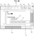
- FIGS. 8A and 8B are enlarged views of other examples of the second screen 300 displayed on the first screen 240.
- the display processor 12A may add new information to the related information displayed on the second screen 300. Adding new information may be performed, for example, by pressing the "Text" button 304.
- the new information referred to herein is, for example, text information or attention-requiring information.
- an enclosure line 310 may be added an example of attention-requiring information or a memo 311 may be added as an example of text information.
- the attention-requiring information may include, for example, circles, underlines, checkmarks, markings, etc.
- the related information displayed on the second screen 300 may include text information. Since the second screen 300 may be used as a text message for the user (worker), it is possible to enhance a work efficiency.
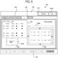
- FIG. 9 is a front view illustrating another example of a state where the plurality of second screens 300A and 300B are displayed on the first screen 240.
- the first screen 240 illustrated in FIG. 9 is a screen where the "Alarm" button of the navigation panel 241 is selected and a "Monitor Data" tag is selected and displayed.
- the first screen 240 displays a monitor data list 250.
- the monitor data list 250 includes an information button 251.
- the second screen 300A is displayed on the first screen 240.
- the second screen 300A includes movement buttons 320 as an example of a button accepting a user touch operation to instruct the movement of the second screen 300A.
- the movement buttons 320 are provided at upper, lower, right, and left sides of the second screen 300A and are capable of moving the second screen 300A vertically and horizontally.
- the movement buttons 320 accept a touch operation even when the user is wearing gloves, enabling the movement of the second screen 300A.
- the related information displayed on the second screen 300B is monitor data indicating an operational status of the substrate processing apparatus 2. In this case, it is possible to perform editing on the first screen 240 while viewing the monitor data.
- the second screen 300B includes the movement buttons 320 as an example of a button accepting a user touch operation to instruct the movement of the second screen 300B.
- the movement buttons 320 are provided at upper, lower, right, and left sides of the second screen 300B and are capable of moving the second screen 300B vertically and horizontally.
- the movement buttons 320 accepts a touch operation even when the user is wearing gloves, enabling the movement of the second screen 300B.
- the monitor data list 250 of the first screen 240 displays monitor data names, which are the names of monitor data indicating the operational status of the substrate processing apparatus 2, and a plurality of items regarding the monitor data names.
- monitor data names which are the names of monitor data indicating the operational status of the substrate processing apparatus 2, and a plurality of items regarding the monitor data names.
- "aa01" to "aa11" of the monitor data list 250 are an example of the monitor data names.
- the second screen 300B display the monitor data names and some items among the plurality of items.
- the monitor data list 250 of the first screen 240 may not be able to display the entire data due to screen size constraints. In the example of FIG.
- the monitor data list 250 of the first screen 240 lists monitor data "aa01" to "aa11," although the monitor date list 250 includes, for example, from “aa01” to "aa40.”
- the second screen 300B displays the entire monitor data names from “aa01” to "aa40” but extracts and displays some items (herein, item "Data”) among the plurality of items of the monitor data list 250. This enables the second screen 300B to display some of the monitor data names and items that may not be fully displayed on the first screen 240, enabling an editing operation.
- the second screen 300B may be configured to display a list of the monitor data names.
- the plurality of items included in the monitor data list 250 are not displayed on the second screen 300B.
- the second screen 300B to display a list of the monitor data names that may not be fully displayed on the first screen 240, enabling an editing operation.
- the items displayed on the second screen 300B may be appropriately selected by the user. This enables displaying information that matches the user's purpose, facilitating easy understanding of desired information.
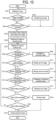
- FIG. 10 is a flowchart illustrating an example of a flow of screen display processing according to the embodiments of the present disclosure.
- step S101 of FIG. 10 the CPU 12 causes the display 24 to display, for example, the first screen 240 illustrated in FIG. 5 as described above and to wait for a user input.
- step S102 the CPU 12 determines whether a screen transition button (e.g., various buttons arranged on the navigation panel 241) is pressed for the first screen 240.
- a screen transition button e.g., various buttons arranged on the navigation panel 241
- step S103 the CPU 12 transitions to a screen corresponding to the screen transition button pressed in step S102, and returns to step S101 to repeat the processing.
- step S104 the CPU 12 determines whether a screenshot button (e.g., the Sc button 243A) is pressed.
- a screenshot button e.g., the Sc button 243A
- the CPU 12 determines that the screenshot button is not pressed (negative determination)
- it returns to step S101 to repeat the processing.
- the CPU 12 determines that the screenshot button is pressed (affirmative determination)
- it proceeds to step S105.
- step S105 the CPU 12 converts, for example, at least part of apparatus information displayed on the first screen 240 illustrated in FIG. 5 as described above into image data.
- step S106 the CPU 12 displays the image data converted in step S105 on the second screens 300A and 300B, for example, as illustrated in FIG. 6 described above, and displays the second screens 300A and 300B on the first screen 240.
- step S107 the CPU 12 causes, for example, the second screen 300 illustrated in FIG. 7 as described above to wait for a user input.
- step S108 the CPU 12 determines whether an enlarging or reducing button (e.g., the reducing button 302 or the enlarging button 303) is pressed for the captured image P1 of the second screen 300, for example, as illustrated in FIG. 7 described above.
- an enlarging or reducing button e.g., the reducing button 302 or the enlarging button 303
- it proceeds to step S109.
- the CPU 12 determines that the enlarging or reducing button is not pressed (negative determination)
- step S109 the CPU 12 performs an operation of enlarging or reducing the captured image P1, and then returns to step S107 to repeat the processing.
- step S110 the CPU 12 determines whether a text addition button (e.g., the "Text" button 304) is pressed for the captured image P1 of the second screen 300.
- a text addition button e.g., the "Text” button 304
- it proceeds to step S111.
- the CPU 12 determines that the text addition button is not pressed (negative determination)
- it proceeds to step S 112.
- step S111 the CPU 12 adds text (e.g., the memo 311) to the captured image P1, for example, as illustrated in FIGS. 8A and 8B , and then returns to step S107 to repeat the processing.
- text e.g., the memo 311
- step S 112 the CPU 12 determines whether a second screen movement button (e.g., the movement button 320) is pressed for either the second screen 300A or the second screen 300B, for example, as illustrated in FIG. 9 .
- a second screen movement button e.g., the movement button 320
- the CPU 12 determines that the second screen movement button is pressed (affirmative determination)
- it proceeds to step S113.
- the CPU 12 determines that the second screen movement button is not pressed (negative determination)
- step S113 the CPU 12 moves the second screen 300A or 300B in response to the user's touch operation, and then returns to step S107 to repeat the processing.
- step S114 the CPU 12 determines whether the operation of enlarging or reducing is instructed for either the second screen 300A or 300B, for example, as illustrated in FIG. 9 described above.
- the CPU 12 determines that the operation of enlarging or reducing is instructed (affirmative determination)
- it proceeds to step S115.
- the CPU 12 determines that the operation of enlarging or reducing is not instructed (negative determination)
- it proceeds to step S116.
- step S115 the CPU 12 performs the operation of enlarging or reducing the second screen 300A or 300B, and then returns to step S107 to repeat the processing.
- step S116 the CPU 12 determines whether a read button (e.g., the "Read” button 305) for instructing reading of new image data from the memory 14 is pressed, for example, as illustrated in FIG. 7 described above. It is determined whether the read button is pressed. When the CPU 12 determines that the read button is pressed (affirmative determination), it proceeds to step S117. When the CPU 12 determines that the read button is not pressed (negative determination), it proceeds to step S118.
- a read button e.g., the "Read” button 305
- step S117 the CPU 12 reads new image data from the memory 14 in response to a user's operation, displays the same on the second screen 300, and then returns to step S107 to repeat the processing.
- step S118 the CPU 12 determines whether a save button (e.g., the "Save” button 306) is pressed for the captured image P1 of the second screen 300, for example, as illustrated in FIG. 7 described above.
- a save button e.g., the "Save” button 306
- step S119 the CPU 12 stores the captured image P1 of the second screen 300 in the memory 14, and then proceeds to step S121.
- step S120 the CPU 12 determines whether a close button (e.g., the close button 307) is pressed for the second screen 300, for example, as illustrated in FIG. 7 described above.
- a close button e.g., the close button 307
- the CPU 12 determines that the close button is pressed (affirmative determination)
- it proceeds to step S121.
- the CPU 12 determines that the close button is not pressed (negative determination)
- it returns to step S107 to repeat the processing.
- step S121 the CPU 12 performs an operation of closing the second screen 300 and terminating the screen display processing.
- the gas introduced via the gas introduction pipe 47 is used to process each substrate 200.
- the gas is used to form a film on the substrate 200.
- the supply of gas via the gas introduction pipe 47 is stopped, and the substrate processing is terminated.
- the boat 217 is unloaded from the process chamber 201.
- the embodiments of the present disclosure may employ a method of processing a substrate, which includes: for the display 24, operating the first screen 240 while the second screen 300 displaying the related information is displayed on the first screen 240; and loading the substrate 200 into the substrate processing apparatus 2 with the first screen 240 operated.
- the embodiments of the present disclosure may employ a method of manufacturing a semiconductor device, which includes processing the substrate 200 in the process chamber 201 included in the substrate processing apparatus 2.
- a main screen (first screen) remains operable while a sub-screen (second screen) displaying the related information is displayed on the main screen.
- This enables, e.g., editing of apparatus information on the main screen while viewing the related information on the sub screen, resulting in an improvement in an efficiency of operations on the main screen.
- the substrate processing apparatus and the control apparatus are described above by way of example.
- the embodiments may also a form of programs that causes a computer to execute functions of the substrate processing apparatus and the control apparatus.
- the embodiments may also a form of a non-transitory recording medium readable by the computer storing these programs.
- the configurations of the substrate processing apparatus and the control apparatus described in the embodiments are given by way of example and may be modified according to situations within the scope without departing from the gist of the present disclosure.
- the embodiments are not limited thereto.
- the embodiments may be realized, for example, by a hardware configuration or a combination of hardware and software configurations.
- an example of performing a predetermined processing on a substrate surface by using a batch-type substrate processing apparatus configured to process a plurality of substrates at once is not limited to the above-described embodiments, and for example, may be suitably applied to a case where a predetermined processing is performed on the substrate surface by using single-wafer type substrate processing apparatus configured to process one or several substrates at once.
- an example of performing a predetermined processing on the substrate surface by using a substrate processing apparatus including a hot-wall-type process furnace is described.
- the present disclosure is not limited to the above-described embodiments, and may be suitably applied to a case where a predetermined processing is performed on the substrate surface by using a substrate processing apparatus including a cold-wall-type process furnace as well.
Landscapes
- Engineering & Computer Science (AREA)
- General Engineering & Computer Science (AREA)
- Theoretical Computer Science (AREA)
- Physics & Mathematics (AREA)
- General Physics & Mathematics (AREA)
- Human Computer Interaction (AREA)
- Automation & Control Theory (AREA)
- Manufacturing & Machinery (AREA)
- Quality & Reliability (AREA)
- User Interface Of Digital Computer (AREA)
- Testing And Monitoring For Control Systems (AREA)
- Container, Conveyance, Adherence, Positioning, Of Wafer (AREA)
Abstract
Description
- This application is based upon and claims the benefit of priority from
Japanese Patent Application No. 2023-136276, filed on August 24, 2023 - The present disclosure relates to a substrate processing apparatus, a substrate processing method, a method of manufacturing a semiconductor device, a program, and a control apparatus.
- For example, in the related art, there is disclosed a substrate processing apparatus capable of displaying an operable sub-screen superimposed on a main screen that displays apparatus information used in the substrate processing apparatus.
- By the way, when operating a substrate processing apparatus, a user does so on an operation screen. Therefore, an improvement in an efficiency of operations on the operation screen is desired.
- Some embodiments of the present disclosure provide a technique capable of improving an efficiency of operations on a main screen where apparatus information used in a substrate processing apparatus may be displayed or operated.
- According to some embodiments of the present disclosure, there is provided a technique that includes a controller configured to be capable of operating a first screen capable of displaying or operating apparatus information that is used in a substrate processing apparatus while at least one second screen capable of displaying at least one piece of related information which is related to the apparatus information is displayed on the first screen.
- The accompanying drawings, which are incorporated in and constitute a part of the specification, illustrate embodiments of the present disclosure.
-
FIG. 1 is a perspective view schematically illustrating an example of a substrate processing apparatus according to some embodiments of the present disclosure. -
FIG. 2 is a schematic configuration view of a process furnace in the substrate processing apparatus illustrated inFIG. 1 . -
FIG. 3 is a block diagram illustrating an example of a configuration of a control apparatus included in a substrate processing apparatus according to some embodiments of the present disclosure. -
FIG. 4 is a block diagram illustrating an example of a functional configuration of a substrate processing apparatus according to some embodiments of the present disclosure. -
FIG. 5 is a front view schematically illustrating an example of a first screen displayed on a display. -
FIG. 6 is a front view illustrating an example of a state where a plurality of second screens are displayed on a first screen. -
FIG. 7 is an enlarged view of an example of a second screen displayed on a first screen. -
FIG. 8A is an enlarged view of another example of a second screen displayed on a first screen. -
FIG. 8B is an enlarged view of another example of the second screen displayed on a first screen. -
FIG. 9 is a front view illustrating another example of a state where a plurality of second screens are displayed on a first screen. -
FIG. 10 is a flowchart illustrating an example of a flow of screen display processing according to the embodiment. - Reference will now be made in detail to various embodiments, examples of which are illustrated in the accompanying drawings. In the following detailed description, numerous specific details are set forth in order to provide a thorough understanding of the present disclosure. However, it will be apparent to one of ordinary skill in the art that the present disclosure may be practiced without these specific details. In other instances, well-known methods, procedures, systems, and components are not described in detail so as not to unnecessarily obscure aspects of the various embodiments.
- Hereinafter, some embodiments of the present disclosure will be described mainly with reference to
FIGS. 1 to 10 . In addition, the drawings used in the following description are schematic, and dimensional relationships, ratios, and the like of the respective components illustrated in the drawings may not match actual ones. Further, dimensional relationships, ratios, and the like of the respective components among plural drawings may not match one another. Further, the present disclosure is not limited to the following embodiments in any way, and modifications may be made within the scope of the present disclosure as appropriate. - First, an outline of a substrate processing apparatus according to the embodiments of the present disclosure will be described with reference to
FIGS. 1 and2 . -
FIG. 1 is a perspective view schematically illustrating an example of asubstrate processing apparatus 2 according to the embodiments of the present disclosure. - As illustrated in
FIG. 1 , thesubstrate processing apparatus 2 according to the embodiments includes acassette 100, which accommodates a plurality ofsubstrates 200 made of, e.g., silicon, and ahousing 101. Acassette stage 105, which serves as a substrate container delivery stage, is installed inside thehousing 101 at a cassette loading/unloading port (not illustrated). Thecassette 100 is configured to be loaded onto thecassette stage 105 and to be unloaded from thecassette stage 105 by an in-process transporter (not illustrated). - A
cassette shelf 109, which serves as a substrate container mounting shelf, is installed approximately at the center of thehousing 101 in a front-rear direction. Thecassette shelf 109 is configured to store a plurality ofcassettes 100 in a plurality of rows and columns. Thecassette shelf 109 is provided with acarriage shelf 123 where thecassettes 100 are stored. Further, aspare cassette shelf 110 is provided above thecassette stage 105 and is configured to temporarily store thecassettes 100. Acassette elevator 115, which is a substrate container lifting mechanism configured to be capable of moving up or down while holding thecassettes 100, and acassette carrier 114 are provided between thecassette stage 105 and thecassette shelf 109. Thecassette elevator 115 and thecassette carrier 114 are configured to, through continuous operations thereof, transport thecassettes 100 among thecassette stage 105, thecassette shelf 109, and thespare cassette shelf 110. - A
substrate carrier 112 configured to be capable of rotating or linearly driving thesubstrates 200 in a horizontal direction and acarrier elevator 113 configured to raise or lower thesubstrate carrier 112 are provided behind thecassette shelf 109. Thecarrier elevator 113 is installed at a right end of thehousing 101. Thecarrier elevator 113 and thesubstrate carrier 112 are configured to, through continuous operations thereof, charge or discharge thesubstrates 200 into or from aboat 217, which serves as a substrate holder, by using atweezer 111, which is a substrate holding piece of thesubstrate carrier 112, as a mounter of thesubstrates 200. - A
process furnace 202 is provided at a rear upper side of thehousing 101. A lower end of theprocess furnace 202 is configured to be opened or closed by afurnace opening shutter 116, which serves as an opening/closing mechanism for a furnace opening. Aboat elevator 121, which serves as a substrate holder lifting mechanism as a lifting mechanism configured to raise or lower theboat 217 into or from theprocess furnace 202 is provided below theprocess furnace 202. Aseal cap 219, which serves as a lid, is horizontally placed at alifter 122, which is a connector connected to a lifting stand of theboat elevator 121, such that theseal cap 219 is configured to vertically support theboat 217 and to be capable of closing a lower end of theprocess furnace 202. Theboat 217 serving as a substrate holder includes a plurality ofboat columns 221, and is configured to horizontally hold a plurality of wafers 200 (e.g., 50 or more and 150 or less substrates) with centers of thesubstrates 200 aligned with one another in a vertical direction. - As illustrated in
FIG. 1 , acleaner 118 is provided above thecassette shelf 109 and is constituted by a supply fan and a dust-proof filter to supply clean air, which is an atmosphere purified from an external air inflow from aduct 124. Thus, thecleaner 118 is configured to circulate the clean air to the interior of thehousing 101. - Next, an operation of the
substrate processing apparatus 2 according to the embodiments of the present disclosure will be described. As illustrated inFIG. 1 , thecassette 100 is loaded from the cassette loading/unloading port. Thecassette 100 is automatically transported to a designated shelf position on either thecassette shelf 109 or thespare cassette shelf 110, where thecassette 100 is temporarily stored. Thereafter, thecassette 100 is carried from either thecassette shelf 109 or thespare cassette shelf 110 to thecarriage shelf 123, or is directly transported to thecarriage shelf 123. - Once the
cassette 100 is carried onto thecarriage shelf 123, thesubstrate 200 is picked up from thecassette 100 by thetweezer 111 of thesubstrate carrier 112 through a substrate entrance, and is charged into theboat 217. After delivering thesubstrate 200 to theboat 217, thesubstrate carrier 112 returns to thecassette 100 to charge thenext substrate 200 into theboat 217. - Once a predetermined number of
substrates 200 are charged into theboat 217, the lower end of theprocess furnace 202, which was closed by thefurnace opening shutter 116, is opened by thefurnace opening shutter 116. Subsequently, theboat 217 holding a group ofsubstrates 200 is loaded into theprocess furnace 202 when theseal cap 219 is raised by theboat elevator 121. - After loading, the
substrates 200 are subjected to arbitrary processing in theprocess furnace 202. After the processing, thesubstrates 200 and thecassette 100 are unloaded out of thehousing 101 in the reverse procedure. -
FIG. 2 is a schematic configuration view of theprocess furnace 202 in thesubstrate processing apparatus 2 illustrated inFIG. 1 . - The
process furnace 202 includes areaction tube 203. Thereaction tube 203 is made of, for example, a heat-resistant and non-metallic material such as quartz (SiO2) or silicon carbide (SiC), and formed in a cylindrical shape with a closed upper end and an open lower end. - A
process chamber 201 is formed inside thereaction tube 203. Theboat 217 serving as a substrate holder is inserted from below into theprocess chamber 201, such that thesubstrates 200 held in a horizontal posture by theboat 217 are accommodated while being aligned with one another in multiple stages along a vertical direction. Theboat 217 accommodated in theprocess chamber 201 is configured to be rotatable in a state where the plurality ofsubstrates 200 are mounted on theboat 217, while maintaining an airtightness of theprocess chamber 201, when arotating shaft 44 is rotated by arotator 43. - A manifold 45 is arranged concentrically with the
reaction tube 203 below thereaction tube 203. The manifold 45 is made of, for example, a metallic material such as stainless steel, and is formed in a cylindrical shape with open upper and lower ends. Thereaction tube 203 is supported in a vertical orientation from the lower end side by themanifold 45. In other words, thereaction tube 203 forming theprocess chamber 201 is erected vertically via themanifold 45, thus constituting theprocess furnace 202. A lower end of the manifold 45 is configured to be airtightly sealed by theseal cap 219 when theboat elevator 121 moves up. Aseal 219a such as an O-ring is provided between the lower end of the manifold 45 and theseal cap 219 to airtightly seal theprocess chamber 201. - Further, the manifold 45 is connected to each of a
gas introduction pipe 47 configured to introduce, e.g., a precursor gas or a purge gas into theprocess chamber 201 and anexhaust pipe 48 configured to discharge the gas from theprocess chamber 201. A pressure of theprocess chamber 201 is controlled while anAPC valve 35 is regulated based on detection results of a pressure sensor (not illustrated). - A
heater 207, which serves as a heating mechanism, is arranged concentrically with thereaction tube 203 around an outer periphery of thereaction tube 203. Theheater 207 is configured to heat theprocess chamber 201 so that a temperature distribution of theentire process chamber 201 becomes a uniform or predetermined temperature distribution. - Herein, as illustrated in
FIG. 1 , thesubstrate processing apparatus 2 includes acontrol apparatus 10 serving as a main controller, and thecontrol apparatus 10 controls thesubstrate processing apparatus 2. Thecontrol apparatus 10 may be built into thesubstrate processing apparatus 2 or may be installed in an accessible manner outside thesubstrate processing apparatus 2. Thecontrol apparatus 10 controls, e.g., an operation of each component constituting thesubstrate processing apparatus 2 and theprocess furnace 202. - Next, a configuration of a control system of the
substrate processing apparatus 2 according to the embodiments of the present disclosure will be described with reference toFIG. 3 . -
FIG. 3 is a block diagram illustrating an example of a configuration of thecontrol apparatus 10 included in thesubstrate processing apparatus 2 according to the embodiments. - As illustrated in
FIG. 3 , thesubstrate processing apparatus 2 includes thecontrol apparatus 10 serving as a main controller, anexternal communicator 21, anexternal memory 22, anoperator 23, adisplay 24, aprocess controller 25, and atransport controller 26. - Further, the
control apparatus 10 includes acontroller 11, amemory 14, and an I/O (also referred to as "I/O port") 15. Thecontroller 11 includes a central processing unit (CPU) 12 and a random access memory (RAM) 13. - The
control apparatus 10 is connected to theoperator 23 and is also connected to theprocess controller 25 and thetransport controller 26 via the I/O 15. Being electrically connected to each of theprocess controller 25 and thetransport controller 26 via the I/O 15, thecontrol apparatus 10 is configured to be capable of performing, e.g., transmission and reception of each data or downloading and uploading of each file. - The
control apparatus 10 is connected to an external host computer (not illustrated) via theexternal communicator 21. Therefore, even in a case where thesubstrate processing apparatus 2 is installed in a clean room, the host computer may be located outside the clean room such as in an office. Further, thecontrol apparatus 10 is connected to theexternal memory 22, which serves as a mount into which a universal serial bus (USB) memory, etc. as an example of a recording medium is detachably inserted. - The
operator 23 is integrated with thedisplay 24, or is connected to thedisplay 24 via, e.g., a video cable. Thedisplay 24 is, for example, a liquid crystal display panel. Thedisplay 24 is configured to display each operation screen configured to operate thesubstrate processing apparatus 2. The operation screen includes a screen configured to monitor statuses of a substrate process system controlled by theprocess controller 25 and a substrate transport system controlled by thetransport controller 26. Thedisplay 24 may be further provided with each operation button as an input component to input operational instructions for the substrate process system and the substrate transport system. Theoperator 23 enables thedisplay 24 to display information generated in thesubstrate processing apparatus 2 through the operation screen. Further, theoperator 23 enables, for example, the output of the information displayed on thedisplay 24 to a device such as a USB memory inserted into theexternal memory 22. Theoperator 23 receives input data (input instructions) from the operation screen displayed on thedisplay 24, and transmits the input data to thecontrol apparatus 10. Further, theoperator 23 is configured to receive instructions (control instructions) to execute an arbitrary substrate processing recipe (also referred to as "process recipe") among a plurality of recipes stored in thememory 14 or a recipe developed in theRAM 13 and to transmit the instructions to thecontrol apparatus 10. In addition, theoperator 23 and thedisplay 24 may be configured with a touch panel. Herein, theoperator 23 and thedisplay 24 are provided separately from thecontrol apparatus 10 but may be integrally included in thecontrol apparatus 10. - The
process controller 25, although not illustrated herein, includes a temperature controller, a gas flow rate controller, and a pressure controller. Each of the temperature controller, the gas flow rate controller, and the pressure controller constitutes a sub-controller and is electrically connected to theprocess controller 25, enabling transmission and reception of each data, downloading and uploading of each file, or the like. In addition, theprocess controller 25 and each sub-controller (temperature controller, gas flow rate controller, and pressure controller) may be configured separately or integrally. - The
transport controller 26, although not illustrated herein, includes a mechanism controller. The mechanism controller is configured to control each of a drive system, a rotator system, and a lifting system of thesubstrate processing apparatus 2. Thetransport controller 26 is configured to control a transport operation of each transport mechanism included in thesubstrate processing apparatus 2. - In addition, the processing of the
substrate 200 is performed, for example, according to a recipe that defines a processing condition for thesubstrate 200. The recipe is stored in thememory 14, and thecontroller 11 acquires the stored recipe during substrate processing, thus controlling the substrate processing based on the processing condition defined in the recipe. The recipe may be stored in theexternal memory 22 as well as thememory 14. Examples of theexternal memory 22 include a USB memory, compact disc (CD), digital versatile disc (DVD), and external hard disk. Further, the recipe may be acquired from an external device via theexternal communicator 21. - In addition, the
control apparatus 10, theprocess controller 25, and thetransport controller 26 according to the embodiments are not limited to a dedicated system and may be realized by using a conventional computer system. For example, each controller configured to execute a predetermined processing may be configured by installing a program for executing the above-described processing from a recording medium (such as CD-ROM or USB) storing that program to a general-purpose computer. - Then, there is an arbitrary way of supplying these programs. The programs may be supplied through a predetermined recording medium as described above, or may be supplied through, for example, communication lines, communication networks, and communication systems.
- The
control apparatus 10 is constituted as a computer equipped with theCPU 12,RAM 13,memory 14, and I/O 15. Thememory 14 stores, e.g., each recipe file for recipes that define processing conditions and processing procedures, a control program file for executing each recipe file, a parameter file (setting value file) for setting processing conditions and processing procedures, an error-processing program file, an error-processing parameter file, a file for various screens including an input screen configured to input processing parameters, and a file for various icons (none of which are illustrated). In addition, thecontrol apparatus 10 is connected to a network such as the Internet, local area network (LAN), or wide area network (WAN) by using theexternal communicator 21, thus enabling communication with external devices via the network. - Further, the
memory 14 may be, for example, a hard disk drive (HDD), solid state drive (SSD), or flash memory. Thememory 14 stores a screen display processing program for executing a screen display processing according to the embodiments of the present disclosure. - The screen display processing program may be installed in advance in the
substrate processing apparatus 2, for example. The screen display processing program may be realized by being recorded on a non-volatile recording medium or being distributed via a network, and appropriately being installed in thesubstrate processing apparatus 2. In addition, examples of the non-volatile recording medium include a compact disc read only memory (CD-ROM), magneto-optical disk, HDD, digital versatile disc read only memory (DVD-ROM), flash memory, memory card, and USB. - The
CPU 12 of thesubstrate processing apparatus 2 according to the embodiments of the present disclosure functions as adisplay processor 12A illustrated inFIG. 4 by writing the screen display processing program stored in thememory 14 into theRAM 13 and executing the same. -
FIG. 4 is a block diagram illustrating an example of a functional configuration of thesubstrate processing apparatus 2 according to the embodiments of the present disclosure. - As illustrated in
FIG. 4 , thedisplay 24 includes a user interface (UI) 24A and ascreen 24B. TheUI 24A acquires at least a part of information displayed on thescreen 24B as image data and transmits the same to thescreen 24B. Further, theUI 24A receives inputs from the user and processes the same. Thescreen 24B presents the image data transmitted from theUI 24A to the user. - The
display 24 may display a first screen and at least one second screen. The first screen is a main screen (also referred to as a "parent screen"), and the second screen is a sub screen (also referred to as a "child screen"). The first screen is a screen where apparatus information used in thesubstrate processing apparatus 2 may be displayed or operated. For example, the first screen enables buttons on the screen to be operated, thus enabling editing of recipes, parameters, and the like. The apparatus information displayed on the first screen includes, for example, information indicating a state of thesubstrate processing apparatus 2 and information including recipes, parameters, etc. to be edited. On the other hand, the at least one second screen is a screen where at least one piece of related information which is related to the apparatus information on the first screen may be displayed. For example, the second screen displays captured images of at least part of the first screen, pre-stored images, text messages, videos, and the like. The related information displayed on the second screen includes, for example, apparatus information described in the captured images and text messages. - The
display processor 12A enables the first screen of thedisplay 24 to be operated while the second screen displaying the related information is displayed on the first screen. In other words, while the second screen displaying the related information is displayed as superimposed on the first screen, thedisplay processor 12A enables operations on the first screen, for example, pressing buttons, operating scroll bars, editing data such as inputting or modifying data, and the like. In addition, thedisplay processor 12A enables processing such as loading, saving, and renaming image files stored in thememory 14. Thedisplay processor 12A enables addition or deletion of text, images, and the like on image data such as captured images. This enables the first screen to be operated while comparing the apparatus information on the first screen with the related information on the second screen on the same screen, for example, on the same display screen. -
FIG. 5 is a front view schematically illustrating an example of afirst screen 240 displayed on thedisplay 24. - The
first screen 240 illustrated inFIG. 5 includes anavigation panel 241, atitle panel 242, and an apparatusinformation display area 244. Thefirst screen 240 is a screen configured to display apparatus information used in thesubstrate processing apparatus 2 and is structured hierarchically. - The
navigation panel 241 includes a plurality of buttons arranged to designate thefirst screen 240 to be displayed. Thenavigation panel 241 is an area where the plurality of buttons are fixed. The plurality of buttons arranged on thenavigation panel 241 include, for example, a "Job" button, a "System" button, a "Transfer" button, a "Maintenance" button, a "Setup" button, and an "Alarm" button. When any one of the plurality of buttons arranged on thenavigation panel 241 is pressed, transition to a screen ofcorresponding apparatus information 245 occurs. - Specifically, when the "Job" button is selected, transition to a screen displaying apparatus information regarding a job occurs. When the "System" button is selected, transition to a screen displaying apparatus information regarding a system occurs. When the "Transfer" button is selected, transition to a screen displaying apparatus information regarding substrate transport occurs. When the "Maintenance" button is selected, transition to a screen displaying apparatus information regarding maintenance occurs. When the "Setup" button is selected, transition to a screen displaying apparatus information regarding setup occurs. When the "Alarm" button is selected, transition to a screen displaying apparatus information regarding an alarm occurs. In the example of
FIG. 5 , the "Alarm" button is selected, corresponding apparatus information is displayed. - The
title panel 242 is an area configured to display information regarding the entire system. Abutton arrangement area 243 is fixedly provided in thetitle panel 242. Thebutton arrangement area 243 includes, for example, a screen shot (Sc)button 243A. TheSc button 243A is a button for instructing a screenshot and is an example of an instructor. The screenshot is, for example, a function of storing the apparatus information as image data and a function of capturing at least a partial area of the first screen. An image acquired with the "screenshot" may be displayed, for example, as a sub screen superimposed on the main screen. In addition to theSc button 243A, thebutton arrangement area 243 includes a Me button for instructing the display of messages, a Ta button for instructing the execution of tasks, a Pr button for switching between English text and Japanese text, and the like. - The apparatus
information display area 244 is at the same hierarchical level as each button of thenavigation panel 241 and displays theapparatus information 245 to be edited. In other words, thenavigation panel 241 and the apparatusinformation display area 244 are displayed at a first hierarchical area, while theapparatus information 245 is displayed at a second hierarchical area. - In the example of
FIG. 5 , since the "Alarm" button of thenavigation panel 241 is selected, theapparatus information 245 corresponding to the "Alarm" button is displayed. Theapparatus information 245 includes various items such as "Current Alarm," "Alarm History," "Alarm Monitor," and so on. These items such as "Current Alarm," "Alarm History," "Alarm Monitor," and so on may be switched and displayed by using tags. - In the example of
FIG. 5 , since the "Current Alarm" tag is selected, theapparatus information 245 corresponding to the "Current Alarm" tag is displayed at a third hierarchical area. Theapparatus information 245 includes various items such as "File list," "Line status," and so on. These items such as "File list, "Line status," and so on may be switched and displayed by using tags. Herein, the "File list" tag is selected, so that afile list 247 to be edited is displayed. Then, a "A42" file of the displayedfile list 247 is selected, andalarm information 248 corresponding to "A42" is displayed. - A
second screen 300 displays related information which is related to the apparatus information on thefirst screen 240. Thedisplay processor 12A enables thefirst screen 240 to be operable while thesecond screen 300 displaying the related information is displayed on thefirst screen 240. Specifically, with thesecond screen 300 displayed on thefirst screen 240, thedisplay processor 12A enables operations such as operating various buttons arranged on each of thenavigation panel 241 and thetitle panel 242 or editing various pieces of information on thefirst screen 240. - The
Sc button 243A may instruct, for example, creation of a copied image (i.e., a captured image) of thefirst screen 240. In this case, the related information displayed on thesecond screen 300 is a copied image of thefirst screen 240 created in response to an instruction by theSc button 243A. This enables the creation of a captured image of thefirst screen 240 by using a simple method. In addition, the captured image acquired from thefirst screen 240 may be captured by designating a range of the entirefirst screen 240 but may be captured by designating a range of a portion of thefirst screen 240. - Further, the
memory 14 may store the copied image of thefirst screen 240 as the related information. In addition, when storing the related information in thememory 14, it is desirable to associate the information with pre-designated information on thefirst screen 240. The pre-designated information on thefirst screen 240 includes, for example, item names of thenavigation panel 241 and names of hierarchies under those item names. As an example, in a case where "Maintenance" of thenavigation panel 241 is selected and "monitor" is selected from "monitor," "editor," and "log," which are hierarches under that item, "Maintenance" and "monitor" would be associated as the pre-designated information on thefirst screen 240. Further, in addition to the item names and the names of hierarchies, the information may also be associated with the date and time the captured image is created. This makes it easier to select the related information when reading the related information later. Specifically, when the information is associated with the date and time, it is possible to track a history such as an alarm along a timeline, thereby improving an efficiency of image operations. - Further, the
memory 14 may be configured to store a plurality of pieces of related information. Thedisplay processor 12A reads the related information from thememory 14 and displays the read related information on thesecond screen 300. This enables reading and referring to a plurality of pieces of related information at a desired timing. The related information may be images obtained by capturing at least a partial area of thefirst screen 240. For example, as illustrated inFIG. 6 , a plurality ofsecond screens first screen 240 may be displayed on thefirst screen 240. -
FIG. 6 is a front view illustrating an example of a state where the plurality ofsecond screens first screen 240. Thefirst screen 240 illustrated inFIG. 6 is a screen where the "Transport" button of thenavigation panel 241 is selected and displayed. For example, when the "Transport" button of thenavigation panel 241 is selected with the plurality ofsecond screens first screen 240 including theapparatus information 245 illustrated inFIG. 5 described above, transition to a screen of theapparatus information 245 illustrated inFIG. 6 occurs. In other words, even when thefirst screen 240 is operated to enable transition of the screen of theapparatus information 245, the plurality ofsecond screens first screen 240 as they are. - In
FIG. 6 , thesecond screen 300A at the upper side, i.e., near thetitle panel 242, is an image obtained by capturing alarm information corresponding to "A11" of thefile list 247 illustrated inFIG. 5 , and thesecond screen 300B at the lower side, i.e., near thenavigation panel 241 is an image obtained by capturing alarm information corresponding to "A42" of thefile list 247 illustrated inFIG. 5 . - When considering the entire areas of the
first screen 240 as related information, it becomes possible to record information on thefirst screen 240 without omission and refer to the same on any screen. Further, when considering a partial area of thefirst screen 240 as related information, it becomes possible to immediately identify a location to be reviewed when reading that information from thememory 14 at a later time. - Further, the related information displayed on the
second screen 300 may be previously stored information from previous operations. Examples of the previously stored information from previous operations include initial setup data stored at a factory before shipping to a customer and data of experiments conducted by the customer after delivery to the customer. -
FIG. 7 is an enlarged view of an example of thesecond screen 300 displayed on thefirst screen 240. - As illustrated in
FIG. 7 , at least one selected from the group of thesecond screen 300 and the related information may be enlarged or reduced for display. - As an example, a captured image P1 of the
first screen 240 is displayed as related information on thesecond screen 300 illustrated inFIG. 7 . Thesecond screen 300 is provided with a minimizingbutton 301 to minimize thesecond screen 300, a reducingbutton 302 to reduce the captured image P1, a enlargingbutton 303 to enlarge the captured image P1, a "Text"button 304 to add text information to the captured image P1, a "Read"button 305 to read and display new image data from thememory 14, a "Save"button 306 to save the captured image P1, aclose button 307 to close thesecond screen 300, and ascrollbar 308 to scroll through the captured image P1. The reducingbutton 302 and the enlargingbutton 303 enable the capture image P1 to be reduced or enlarged. This facilitates easy comparison between the item of thefirst screen 240 to be reviewed and the information on thesecond screen 300. Further, for example, thesecond screen 300 may be enlarged or reduced by dragging a frame around thesecond screen 300. - Further, the
second screen 300 may be movable on thefirst screen 240. In other words, it becomes possible to move thesecond screen 300 closer to the item of thefirst screen 240 to be reviewed. For example, a method of dragging and moving thesecond screen 300 is used. This facilitates easy comparison between the item of thefirst screen 240 to be reviewed and the information on thesecond screen 300. - Herein, as an example, the related information displayed on the
second screen 300 is information indicating an alarm content regarding thesubstrate processing apparatus 2 as illustrated inFIG. 6 described above, or information describing the item displayed on thefirst screen 240. For example, thefirst screen 240 may be operated to enable transition to a display screen regarding an alarm while displaying information indicating the alarm content on thesecond screen 300. In addition, examples of the information describing the item displayed on thefirst screen 240 include help information for the item or information indicating description of terms or description of operations. - Further, the related information displayed on the
second screen 300 may be information indicating a plurality of alarm contents regarding thesubstrate processing apparatus 2, or information describing a plurality of items displayed on thefirst screen 240. In this case, thefirst screen 240 remains operable while a plurality ofsecond screes 300 displaying the information indicating the alarm contents or a plurality ofsecond screens 300 displaying the information describing the items displayed on thefirst screen 240 on are displayed on thefirst screen 240. For example, in a case where each alarm is associated with a plurality of factors, thefirst screen 240 may be operated to enable transition to a display screen regarding the alarm while displaying information indicating the alarm contents on the plurality ofsecond screens 300. - Further, the information indicating the alarm content may be information related to, for example, troubleshooting set for each alarm or for each information describing the item. This enables efficient troubleshooting since transition to various display screens is possible while performing a comparison with a plurality of pieces of information related to troubleshooting.
- Further, recipe information (main recipe information or sub-recipe information) that defines a processing condition for the
substrate 200 may be displayed on thefirst screen 240. Then, the related information displayed on thesecond screen 300 may be at least one piece of information related to the recipe information. In this case, thefirst screen 240 remains operable while one or moresecond screens 300 displaying the information related to the recipe information are displayed on thefirst screen 240. This enables efficient confirmation and editing of the recipe information since it is possible to check the recipe information on thefirst screen 240 while displaying the information related to the recipe information on thesecond screens 300. - Further, the related information displayed on the
second screens 300 may be sub-recipe information or main recipe information linked to the recipe information (main recipe information or sub-recipe information) of thefirst screen 240. This enables checking and editing main recipe information on thefirst screen 240 while displaying sub-recipe information on thesecond screen 300. Alternatively, it is also possible to check and edit sub-recipe information on thefirst screen 240 while displaying main recipe information on thesecond screen 300. - Further, the
first screen 240 may display parameter information of thesubstrate processing apparatus 2. Then, thesecond screen 300 may display comparative parameter information for comparison with the parameter information. The parameter information on thefirst screen 240 is real-time information obtained from thesubstrate processing apparatus 2, and the comparative parameter information on thesecond screen 300 is pre-stored information for comparison. This enables comparing the parameter information on thefirst screen 240 with the comparative parameter information on thesecond screen 300, facilitating easy understanding of the status of the apparatus. - Further, the
display processor 12A may set a plurality of authorities for apparatus information, and may set a browsing or operation authority of the apparatus information for each authority thus set. In addition, as an example, the authority referred to herein is set for customer's supervisor, customer's person in charge, or apparatus manufacturer's person in charge. For example, by enabling the customer's supervisor and the customer's person in charge to browse the apparatus information while disabling the apparatus manufacturer's person in charge from browsing the apparatus information, the apparatus manufacturer's person in charge is unable to browse the parameter information known to the customer alone. As described above, by enabling browsing or operating of the apparatus information for each authority, appropriate information management for each authority becomes possible. -
FIGS. 8A and8B are enlarged views of other examples of thesecond screen 300 displayed on thefirst screen 240. - The
display processor 12A may add new information to the related information displayed on thesecond screen 300. Adding new information may be performed, for example, by pressing the "Text"button 304. The new information referred to herein is, for example, text information or attention-requiring information. Specifically, as illustrated inFIGS. 8A and8B , anenclosure line 310 may be added an example of attention-requiring information or amemo 311 may be added as an example of text information. In addition to theenclosure line 310, the attention-requiring information may include, for example, circles, underlines, checkmarks, markings, etc. By adding theenclosure line 310 or thememo 311 to the captured image P1 as the related information, it is possible to easily understand the previous state when the captured image P1 is read next. - Further, in addition to the image, the related information displayed on the
second screen 300 may include text information. Since thesecond screen 300 may be used as a text message for the user (worker), it is possible to enhance a work efficiency. -
FIG. 9 is a front view illustrating another example of a state where the plurality ofsecond screens first screen 240. Thefirst screen 240 illustrated inFIG. 9 is a screen where the "Alarm" button of thenavigation panel 241 is selected and a "Monitor Data" tag is selected and displayed. - In
FIG. 9 , thefirst screen 240 displays amonitor data list 250. Themonitor data list 250 includes aninformation button 251. When theinformation button 251 is pressed, thesecond screen 300A is displayed on thefirst screen 240. Thesecond screen 300A includesmovement buttons 320 as an example of a button accepting a user touch operation to instruct the movement of thesecond screen 300A. Themovement buttons 320 are provided at upper, lower, right, and left sides of thesecond screen 300A and are capable of moving thesecond screen 300A vertically and horizontally. Themovement buttons 320 accept a touch operation even when the user is wearing gloves, enabling the movement of thesecond screen 300A. - Related information which is related to the
monitor data list 250 is displayed on thesecond screen 300B. The related information displayed on thesecond screen 300B is monitor data indicating an operational status of thesubstrate processing apparatus 2. In this case, it is possible to perform editing on thefirst screen 240 while viewing the monitor data. Similar to thesecond screen 300A, thesecond screen 300B includes themovement buttons 320 as an example of a button accepting a user touch operation to instruct the movement of thesecond screen 300B. Themovement buttons 320 are provided at upper, lower, right, and left sides of thesecond screen 300B and are capable of moving thesecond screen 300B vertically and horizontally. Themovement buttons 320 accepts a touch operation even when the user is wearing gloves, enabling the movement of thesecond screen 300B. - The
monitor data list 250 of thefirst screen 240 displays monitor data names, which are the names of monitor data indicating the operational status of thesubstrate processing apparatus 2, and a plurality of items regarding the monitor data names. Herein, "aa01" to "aa11" of themonitor data list 250 are an example of the monitor data names. Then, thesecond screen 300B display the monitor data names and some items among the plurality of items. In some cases, themonitor data list 250 of thefirst screen 240 may not be able to display the entire data due to screen size constraints. In the example ofFIG. 9 , themonitor data list 250 of thefirst screen 240 lists monitor data "aa01" to "aa11," although themonitor date list 250 includes, for example, from "aa01" to "aa40." In contrast, thesecond screen 300B displays the entire monitor data names from "aa01" to "aa40" but extracts and displays some items (herein, item "Data") among the plurality of items of themonitor data list 250. This enables thesecond screen 300B to display some of the monitor data names and items that may not be fully displayed on thefirst screen 240, enabling an editing operation. - Further, the
second screen 300B may be configured to display a list of the monitor data names. In other words, in this case, the plurality of items included in themonitor data list 250 are not displayed on thesecond screen 300B. This enables thesecond screen 300B to display a list of the monitor data names that may not be fully displayed on thefirst screen 240, enabling an editing operation. Further, the items displayed on thesecond screen 300B may be appropriately selected by the user. This enables displaying information that matches the user's purpose, facilitating easy understanding of desired information. - Next, an action of the
substrate processing apparatus 2 according to the embodiments of the present disclosure will be described with reference toFIG. 10 . -
FIG. 10 is a flowchart illustrating an example of a flow of screen display processing according to the embodiments of the present disclosure. - In step S101 of
FIG. 10 , theCPU 12 causes thedisplay 24 to display, for example, thefirst screen 240 illustrated inFIG. 5 as described above and to wait for a user input. - In step S102, the
CPU 12 determines whether a screen transition button (e.g., various buttons arranged on the navigation panel 241) is pressed for thefirst screen 240. When theCPU 12 determines that the screen transition button is pressed (affirmative determination), it proceeds to step S103. When theCPU 12 determines that the screen transition button is not pressed (negative determination), it proceeds to step S104. - In step S103, the
CPU 12 transitions to a screen corresponding to the screen transition button pressed in step S102, and returns to step S101 to repeat the processing. - On the other hand, in step S104, the
CPU 12 determines whether a screenshot button (e.g., theSc button 243A) is pressed. When theCPU 12 determines that the screenshot button is not pressed (negative determination), it returns to step S101 to repeat the processing. When theCPU 12 determines that the screenshot button is pressed (affirmative determination), it proceeds to step S105. - In step S105, the
CPU 12 converts, for example, at least part of apparatus information displayed on thefirst screen 240 illustrated inFIG. 5 as described above into image data. - In step S106, the
CPU 12 displays the image data converted in step S105 on thesecond screens FIG. 6 described above, and displays thesecond screens first screen 240. - In step S107, the
CPU 12 causes, for example, thesecond screen 300 illustrated inFIG. 7 as described above to wait for a user input. - In step S108, the
CPU 12 determines whether an enlarging or reducing button (e.g., the reducingbutton 302 or the enlarging button 303) is pressed for the captured image P1 of thesecond screen 300, for example, as illustrated inFIG. 7 described above. When theCPU 12 determines that the enlarging or reducing button is pressed (affirmative determination), it proceeds to step S109. When theCPU 12 determines that the enlarging or reducing button is not pressed (negative determination), it proceeds to step S110. - In step S109, the
CPU 12 performs an operation of enlarging or reducing the captured image P1, and then returns to step S107 to repeat the processing. - On the other hand, in step S110, the
CPU 12 determines whether a text addition button (e.g., the "Text" button 304) is pressed for the captured image P1 of thesecond screen 300. When theCPU 12 determines that the text addition button is pressed (affirmative determination), it proceeds to step S111. When theCPU 12 determines that the text addition button is not pressed (negative determination), it proceeds to stepS 112. - In step S111, the
CPU 12 adds text (e.g., the memo 311) to the captured image P1, for example, as illustrated inFIGS. 8A and8B , and then returns to step S107 to repeat the processing. - On the other hand, in
step S 112, theCPU 12 determines whether a second screen movement button (e.g., the movement button 320) is pressed for either thesecond screen 300A or thesecond screen 300B, for example, as illustrated inFIG. 9 . When theCPU 12 determines that the second screen movement button is pressed (affirmative determination), it proceeds to step S113. When theCPU 12 determines that the second screen movement button is not pressed (negative determination), it proceeds to stepS 114. - In step S113, the
CPU 12 moves thesecond screen - On the other hand, in step S114, the
CPU 12 determines whether the operation of enlarging or reducing is instructed for either thesecond screen FIG. 9 described above. When theCPU 12 determines that the operation of enlarging or reducing is instructed (affirmative determination), it proceeds to step S115. When theCPU 12 determines that the operation of enlarging or reducing is not instructed (negative determination), it proceeds to step S116. - In step S115, the
CPU 12 performs the operation of enlarging or reducing thesecond screen - On the other hand, in step S116, the
CPU 12 determines whether a read button (e.g., the "Read" button 305) for instructing reading of new image data from thememory 14 is pressed, for example, as illustrated inFIG. 7 described above. It is determined whether the read button is pressed. When theCPU 12 determines that the read button is pressed (affirmative determination), it proceeds to step S117. When theCPU 12 determines that the read button is not pressed (negative determination), it proceeds to step S118. - In step S117, the
CPU 12 reads new image data from thememory 14 in response to a user's operation, displays the same on thesecond screen 300, and then returns to step S107 to repeat the processing. - On the other hand, in step S118, the
CPU 12 determines whether a save button (e.g., the "Save" button 306) is pressed for the captured image P1 of thesecond screen 300, for example, as illustrated inFIG. 7 described above. When theCPU 12 determines that the save button is pressed (affirmative determination), it proceeds to step S119. When theCPU 12 determines that the save button is not pressed (negative determination), it proceeds to step S120. - In step S119, the
CPU 12 stores the captured image P1 of thesecond screen 300 in thememory 14, and then proceeds to step S121. - On the other hand, in step S120, the
CPU 12 determines whether a close button (e.g., the close button 307) is pressed for thesecond screen 300, for example, as illustrated inFIG. 7 described above. When theCPU 12 determines that the close button is pressed (affirmative determination), it proceeds to step S121. When theCPU 12 determines that the close button is not pressed (negative determination), it returns to step S107 to repeat the processing. - In step S121, the
CPU 12 performs an operation of closing thesecond screen 300 and terminating the screen display processing. - Next, a method of processing a substrate, which uses the
substrate processing apparatus 2, will be described. These processes are controlled by thecontroller 11 based on content of a preset recipe. Once theboat 217 charged with the plurality ofsubstrates 200 is loaded into theprocess chamber 201, the interior of theprocess chamber 201 is maintained at a predetermined pressure and temperature, and a predetermined gas is supplied into theprocess chamber 201 via thegas introduction pipe 47. - The gas introduced via the
gas introduction pipe 47 is used to process eachsubstrate 200. For example, the gas is used to form a film on thesubstrate 200. After a predetermined time elapses, the supply of gas via thegas introduction pipe 47 is stopped, and the substrate processing is terminated. After processing thesubstrate 200 is completed, theboat 217 is unloaded from theprocess chamber 201. - In addition, the embodiments of the present disclosure may employ a method of processing a substrate, which includes: for the
display 24, operating thefirst screen 240 while thesecond screen 300 displaying the related information is displayed on thefirst screen 240; and loading thesubstrate 200 into thesubstrate processing apparatus 2 with thefirst screen 240 operated. - Further, the embodiments of the present disclosure may employ a method of manufacturing a semiconductor device, which includes processing the
substrate 200 in theprocess chamber 201 included in thesubstrate processing apparatus 2. - As described above, according to the embodiments, a main screen (first screen) remains operable while a sub-screen (second screen) displaying the related information is displayed on the main screen. This enables, e.g., editing of apparatus information on the main screen while viewing the related information on the sub screen, resulting in an improvement in an efficiency of operations on the main screen.
- The substrate processing apparatus and the control apparatus according to some embodiments of the present disclosure are described above by way of example. The embodiments may also a form of programs that causes a computer to execute functions of the substrate processing apparatus and the control apparatus. The embodiments may also a form of a non-transitory recording medium readable by the computer storing these programs.
- Moreover, the configurations of the substrate processing apparatus and the control apparatus described in the embodiments are given by way of example and may be modified according to situations within the scope without departing from the gist of the present disclosure.
- Further, the processing flow of the programs described in the above embodiments are also given by way of example, and some steps may be deleted, new steps may be added, or the processing sequence may be changed within the scope without departing from the gist of the present disclosure.
- Further, in the above embodiments, a case where the processing of the embodiments are realized by a software configuration by using a computer through the execution of programs is described, but the embodiments are not limited thereto. The embodiments may be realized, for example, by a hardware configuration or a combination of hardware and software configurations.
- In the above embodiments, an example of performing a predetermined processing on a substrate surface by using a batch-type substrate processing apparatus configured to process a plurality of substrates at once. The present disclosure is not limited to the above-described embodiments, and for example, may be suitably applied to a case where a predetermined processing is performed on the substrate surface by using single-wafer type substrate processing apparatus configured to process one or several substrates at once. Further, in the above-described embodiments, an example of performing a predetermined processing on the substrate surface by using a substrate processing apparatus including a hot-wall-type process furnace is described. The present disclosure is not limited to the above-described embodiments, and may be suitably applied to a case where a predetermined processing is performed on the substrate surface by using a substrate processing apparatus including a cold-wall-type process furnace as well.
- Even when using such a substrate processing apparatus, it is possible to perform each processing by using the same processing procedures and processing conditions as in the above-described embodiments, and to achieve the same effects as the above-described embodiments.
- According to the present disclosure in some embodiments, it is possible to improve an efficiency of operations on a main screen where apparatus information used in a substrate processing apparatus may be displayed or operated.
- While certain embodiments are described above, these embodiments are presented by way of example, and are not intended to limit the scope of the disclosures. Indeed, the embodiments described herein may be embodied in a variety of other forms. Furthermore, various omissions, substitutions and changes in the form of the embodiments described herein may be made without departing from the spirit of the disclosures. The accompanying claims and their equivalents are intended to cover such forms or modifications as would fall within the scope and spirit of the disclosures.
Claims (15)
- A substrate processing apparatus comprising a controller configured to be capable of operating a first screen capable of displaying or operating apparatus information that is used in the substrate processing apparatus while at least one second screen capable of displaying at least one piece of related information which is related to the apparatus information is displayed on the first screen.
- The substrate processing apparatus according to claim 1, further comprising an instructor configured to instruct creation of a copied image that is a captured image of the first screen,
wherein the at least one piece of related information is the copied image of the first screen created in response to an instruction from the instructor. - The substrate processing apparatus according to claim 1, wherein the at least one piece of related information includes a plurality of pieces of related information,wherein the substrate processing apparatus further comprises a memory configured to store the plurality of pieces of related information, andwherein the controller is further configured to be capable of reading the at least one piece of related information from the memory and be capable of displaying the at least one piece of related information thus read on the at least one second screen.
- The substrate processing apparatus according to claim 1, wherein the at least one piece of related information is a captured image of at least a partial area of the first screen, or
wherein the at least one piece of related information is information indicating an alarm content regarding the substrate processing apparatus, or information describing an item displayed on the first screen. - The substrate processing apparatus according to claim 1, wherein the controller is further configured to be capable of displaying at least one selected from the group of the at least one second screen and the at least one piece of related information on an enlarged scale or a reduced scale.
- The substrate processing apparatus according to claim 1, wherein the at least one second screen includes a button to receive an operation by a user touch and instruct movement of the at least one second screen.
- The substrate processing apparatus according to claim 1, wherein the first screen is capable of displaying recipe information that defines a substrate processing condition, andwherein the at least one piece of related information is sub-recipe information or main recipe information linked to the recipe information, orwherein the first screen is capable of displaying parameter information of the substrate processing apparatus, andwherein the at least one second screen is capable of displaying comparative parameter information to be compared with the parameter information.
- The substrate processing apparatus according to claim 1, wherein the controller is further configured to be capable of setting a plurality of authorities for the apparatus information, and setting a browsing or operation authority for the apparatus information for each set authority.
- The substrate processing apparatus according to claim 1, wherein the controller is further configured to be capable of adding new information to the at least one piece of related information displayed on the at least one second screen.
- The substrate processing apparatus according to claim 1, wherein the at least one piece of related information displayed on the at least one second screen is text information or monitor data indicating an operational status of the substrate processing apparatus.
- The substrate processing apparatus according to claim 1, wherein the first screen is capable of displaying a monitor data name that is a name of monitor data indicating an operational status of the substrate processing apparatus and a plurality of items regarding the monitor data name, and
wherein the at least one second screen is capable of displaying the monitor data name and at least one item among the plurality of items or a list of the monitor data name. - A method of processing a substrate, comprising:operating a first screen capable of displaying or operating apparatus information that is used in a substrate processing apparatus while at least one second screen capable of displaying at least one piece of related information which is related to the apparatus information is displayed on the first screen; andloading the substrate into the substrate processing apparatus with the operated first screen.
- A method of manufacturing a semiconductor device, comprising the method according to claim 12.
- A program that causes a substrate processing apparatus to perform each process of the method according to claim 12.
- A control apparatus comprising a controller configured to be capable of operating a first screen capable of displaying or operating apparatus information that is used in a substrate processing apparatus while at least one second screen capable of displaying at least one piece of related information which is related to the apparatus information is displayed on the first screen.
Applications Claiming Priority (1)
| Application Number | Priority Date | Filing Date | Title |
|---|---|---|---|
| JP2023136276A JP2025030730A (en) | 2023-08-24 | 2023-08-24 | SUBSTRATE PROCESSING APPARATUS, SUBSTRATE PROCESSING METHOD, SEMICONDUCTOR DEVICE MANUFACTURING METHOD, PROGRAM, AND CONTROL APPARATUS |
Publications (2)
| Publication Number | Publication Date |
|---|---|
| EP4513536A2 true EP4513536A2 (en) | 2025-02-26 |
| EP4513536A3 EP4513536A3 (en) | 2025-03-19 |
Family
ID=92538488
Family Applications (1)
| Application Number | Title | Priority Date | Filing Date |
|---|---|---|---|
| EP24196145.7A Pending EP4513536A3 (en) | 2023-08-24 | 2024-08-23 | Substrate processing apparatus, method of processing substrate, method of manufacturing semiconductor device, program, and control apparatus |
Country Status (6)
| Country | Link |
|---|---|
| US (1) | US20250068377A1 (en) |
| EP (1) | EP4513536A3 (en) |
| JP (1) | JP2025030730A (en) |
| KR (1) | KR20250030421A (en) |
| CN (1) | CN119517784A (en) |
| TW (1) | TW202510023A (en) |
Citations (1)
| Publication number | Priority date | Publication date | Assignee | Title |
|---|---|---|---|---|
| JP2023136276A (en) | 2022-03-16 | 2023-09-29 | キオクシア株式会社 | semiconductor storage device |
Family Cites Families (5)
| Publication number | Priority date | Publication date | Assignee | Title |
|---|---|---|---|---|
| JP5015015B2 (en) * | 2006-01-27 | 2012-08-29 | 株式会社日立国際電気 | Substrate processing apparatus, recipe display method, substrate processing method, semiconductor device manufacturing method, and recipe transition display method |
| JP5281037B2 (en) | 2008-03-18 | 2013-09-04 | 株式会社日立国際電気 | Substrate processing system, display method of substrate processing system, and program thereof |
| JP6872667B2 (en) * | 2018-03-26 | 2021-05-19 | 株式会社Kokusai Electric | Recipe creation method, semiconductor device manufacturing method and processing device and program |
| JP7418274B2 (en) * | 2020-04-17 | 2024-01-19 | 東京エレクトロン株式会社 | Foreign matter inspection system, foreign matter inspection method, program and semiconductor manufacturing equipment |
| JP7693305B2 (en) * | 2020-12-14 | 2025-06-17 | キヤノン株式会社 | Information processing apparatus, display control method, program, substrate processing apparatus, and method for manufacturing article |
-
2023
- 2023-08-24 JP JP2023136276A patent/JP2025030730A/en active Pending
-
2024
- 2024-07-04 TW TW113125038A patent/TW202510023A/en unknown
- 2024-07-08 CN CN202410905838.9A patent/CN119517784A/en active Pending
- 2024-08-23 EP EP24196145.7A patent/EP4513536A3/en active Pending
- 2024-08-23 US US18/813,856 patent/US20250068377A1/en active Pending
- 2024-08-23 KR KR1020240113586A patent/KR20250030421A/en active Pending
Patent Citations (1)
| Publication number | Priority date | Publication date | Assignee | Title |
|---|---|---|---|---|
| JP2023136276A (en) | 2022-03-16 | 2023-09-29 | キオクシア株式会社 | semiconductor storage device |
Also Published As
| Publication number | Publication date |
|---|---|
| US20250068377A1 (en) | 2025-02-27 |
| TW202510023A (en) | 2025-03-01 |
| JP2025030730A (en) | 2025-03-07 |
| CN119517784A (en) | 2025-02-25 |
| KR20250030421A (en) | 2025-03-05 |
| EP4513536A3 (en) | 2025-03-19 |
Similar Documents
| Publication | Publication Date | Title |
|---|---|---|
| JP5361094B2 (en) | Substrate processing apparatus, display method thereof, setup method, centralized management apparatus, and display method thereof | |
| US12066815B2 (en) | Recipe creation method or apparatus utilizing a series of steps according to a target recipe file for semiconductor manufacturing or substrating processing | |
| JP5275641B2 (en) | Substrate processing apparatus, display method for substrate processing apparatus, control method for substrate processing apparatus, and method for manufacturing semiconductor device | |
| JP6872667B2 (en) | Recipe creation method, semiconductor device manufacturing method and processing device and program | |
| US20250068377A1 (en) | Substrate processing apparatus, method of processing substrate, method of manufacturing semiconductor device, recording medium, and control apparatus | |
| US8510790B2 (en) | Substrate processing apparatus | |
| JP4577889B2 (en) | Substrate processing apparatus, display method for substrate processing apparatus, and data analysis method for substrate processing apparatus | |
| US20250079210A1 (en) | Display processing apparatus, substrate processing apparatus, display method, substrate processing method, method of manufacturing semiconductor device and non-transitory computer-readable recording medium | |
| US20250077057A1 (en) | Processing apparatus, substrate processing apparatus, display method, substrate processing method, method of manufacturing semiconductor device and non-transitory computer-readable recording medium | |
| EP4435545A1 (en) | Control apparatus, substrate processing apparatus, method of manufacturing semiconductor device, and program | |
| TWI917900B (en) | Control device, substrate processing device, processing method, manufacturing method and process of semiconductor device | |
| US20260023370A1 (en) | Processing system, substrate processing apparatus, processing method, method of manufacturing semiconductor device and non-transitory computer-readable recording medium | |
| TW202507447A (en) | Control device, substrate processing device, semiconductor device manufacturing method and program | |
| JP2025151167A (en) | Simulator device, substrate processing apparatus, semiconductor device manufacturing method, and program | |
| CN118676020A (en) | Substrate processing device, method for manufacturing semiconductor device, and recording medium | |
| JP2009117657A (en) | Substrate processing equipment | |
| JP2011003914A (en) | Substrate treatment device, and method of controlling the same |
Legal Events
| Date | Code | Title | Description |
|---|---|---|---|
| PUAI | Public reference made under article 153(3) epc to a published international application that has entered the european phase |
Free format text: ORIGINAL CODE: 0009012 |
|
| STAA | Information on the status of an ep patent application or granted ep patent |
Free format text: STATUS: REQUEST FOR EXAMINATION WAS MADE |
|
| PUAL | Search report despatched |
Free format text: ORIGINAL CODE: 0009013 |
|
| 17P | Request for examination filed |
Effective date: 20241230 |
|
| AK | Designated contracting states |
Kind code of ref document: A2 Designated state(s): AL AT BE BG CH CY CZ DE DK EE ES FI FR GB GR HR HU IE IS IT LI LT LU LV MC ME MK MT NL NO PL PT RO RS SE SI SK SM TR |
|
| AK | Designated contracting states |
Kind code of ref document: A3 Designated state(s): AL AT BE BG CH CY CZ DE DK EE ES FI FR GB GR HR HU IE IS IT LI LT LU LV MC ME MK MT NL NO PL PT RO RS SE SI SK SM TR |
|
| RIC1 | Information provided on ipc code assigned before grant |
Ipc: H01L 21/677 20060101AFI20250210BHEP |
|
| P01 | Opt-out of the competence of the unified patent court (upc) registered |
Free format text: CASE NUMBER: APP_25423/2025 Effective date: 20250528 |