EP4513451A1 - Datenverarbeitungsverfahren und -vorrichtung sowie vorrichtung und system - Google Patents
Datenverarbeitungsverfahren und -vorrichtung sowie vorrichtung und system Download PDFInfo
- Publication number
- EP4513451A1 EP4513451A1 EP23814811.8A EP23814811A EP4513451A1 EP 4513451 A1 EP4513451 A1 EP 4513451A1 EP 23814811 A EP23814811 A EP 23814811A EP 4513451 A1 EP4513451 A1 EP 4513451A1
- Authority
- EP
- European Patent Office
- Prior art keywords
- port
- ports
- optical fiber
- patch cord
- tray
- Prior art date
- Legal status (The legal status is an assumption and is not a legal conclusion. Google has not performed a legal analysis and makes no representation as to the accuracy of the status listed.)
- Pending
Links
Images


Classifications
-
- H—ELECTRICITY
- H04—ELECTRIC COMMUNICATION TECHNIQUE
- H04B—TRANSMISSION
- H04B10/00—Transmission systems employing electromagnetic waves other than radio-waves, e.g. infrared, visible or ultraviolet light, or employing corpuscular radiation, e.g. quantum communication
- H04B10/27—Arrangements for networking
-
- G—PHYSICS
- G02—OPTICS
- G02B—OPTICAL ELEMENTS, SYSTEMS OR APPARATUS
- G02B6/00—Light guides; Structural details of arrangements comprising light guides and other optical elements, e.g. couplings
- G02B6/44—Mechanical structures for providing tensile strength and external protection for fibres, e.g. optical transmission cables
- G02B6/4439—Auxiliary devices
- G02B6/444—Systems or boxes with surplus lengths
- G02B6/44528—Patch-cords; Connector arrangements in the system or in the box
- G02B6/44529—Optical means for identifying patch-cords
-
- G—PHYSICS
- G02—OPTICS
- G02B—OPTICAL ELEMENTS, SYSTEMS OR APPARATUS
- G02B6/00—Light guides; Structural details of arrangements comprising light guides and other optical elements, e.g. couplings
- G02B6/44—Mechanical structures for providing tensile strength and external protection for fibres, e.g. optical transmission cables
- G02B6/4439—Auxiliary devices
- G02B6/444—Systems or boxes with surplus lengths
- G02B6/4453—Cassettes
- G02B6/4454—Cassettes with splices
Definitions
- This application relates to the field of optical networks, and in particular, to a data processing method and apparatus, a device, and a system.
- a system background records information about basic network resources such as an optical distribution frame (optical distribution frame, ODF), an optical cable cross-connect cabinet (optical cable cross-connect cabinet), and an optical fiber patch cord, for example, status information of each port on a splicing tray in the optical distribution frame or the optical cable cross-connect cabinet, and a connection relationship between the optical fiber patch cord and each port of the splicing tray.
- ODF optical distribution frame
- ODF optical cable cross-connect cabinet
- optical fiber patch cord for example, status information of each port on a splicing tray in the optical distribution frame or the optical cable cross-connect cabinet, and a connection relationship between the optical fiber patch cord and each port of the splicing tray.
- This application provides a data processing method and apparatus, a device, and a system. According to the method described in this application, a status of each port on a splicing tray and a connection relationship between an optical fiber patch cord and a port are determined. This facilitates operation, improves efficiency, and facilitates management, operation, and maintenance of an optical network.
- this application provides a data processing method, including: A terminal device obtains a target image captured by a first vision sensor, where the target image includes a tray character label and a plurality of ports on a splicing tray; determines a photographing posture of the first vision sensor based on a posture of the tray character label in the target image, and determines position information of each of the plurality of ports based on the photographing posture; determines a status of each of the plurality of ports based on image data of the plurality of ports in the target image; and sends the position information of each of the plurality of ports and the corresponding status of each port to a system background, so that the system background updates historical statuses of the plurality of ports based on the position information of the plurality of ports and the statuses of the plurality of ports.
- the tray character label is disposed on the splicing tray
- the photographing posture of the first vision sensor is determined based on the posture of the tray character label
- the position information of each port on the splicing tray is determined based on the photographing posture of the first vision sensor. This helps accurately determine the position information of each port, and reduces a photographing requirement.
- the photographing posture includes a photographing height, a photographing distance, and a photographing direction of the first vision sensor
- the posture of the tray character label includes at least a position, a size, and a shape of the tray character label.
- the photographing height, the photographing distance, and the photographing direction of the first vision sensor all affect the target image. Specifically, the photographing height, the photographing distance, and the photographing direction of the first vision sensor affect image data of the tray character label in the target image, and impact on the tray character label is reflected in position, size, shape, and the like of the tray character label.
- the determining statuses of the plurality of ports in the target image based on image data of the plurality of ports in the target image includes: inputting the target image into a trained prediction model, to obtain the statuses of the plurality of ports, where the prediction model is obtained through training based on a large quantity of image samples, the image sample includes at least one port and a label of each of the at least one port, and the label is used to mask a status of the port.
- the prediction model may be obtained through artificial intelligence AI training, and the prediction model is used to predict a status of each port.
- the target image is input into the prediction model, so that the status of each port in the target image can be accurately determined.
- the plurality of ports include any one or a combination of ports included in one or more rows on the splicing tray, ports included in one or more columns on the splicing tray, and all ports on the splicing tray.
- the status of each port in the plurality ports includes an idle state, an occupied state, and an unavailable state.
- the unavailable state of the port means that a flange that is of the port and that is configured to connect to an optical fiber patch cord falls off
- the idle state of the port means that the flange of the port does not fall off and is not connected to the optical fiber patch cord
- the occupied state of the port means that the flange of the port is connected to the optical fiber patch cord.
- identification information is set at both ends of the optical fiber patch cord, and a correspondence exists between the identification information at both ends of the same optical fiber patch cord; and when a port in an occupied state exists in the plurality of ports, the target image includes identification information of one end or both ends of an optical fiber patch cord connected to the port in the occupied state.
- the method further includes: sending, to the system background, position information of the port in the occupied state in the plurality of ports and the identification information of the end of the optical fiber patch cord connected to the port in the occupied state, so that the system background determines a connection relationship between the optical fiber patch cord and the port based on a pre-stored correspondence between the identification information.
- identification information is separately set at two ends of an optical fiber patch cord, and a correspondence exists between the identification information at the two ends of each optical fiber patch cord.
- the terminal device determines, based on the target image, the position information of the port connected to the optical fiber patch cord, and sends the position information and the identification information of the end of the optical fiber patch cord connected to the port to the system background.
- the system background determines the correspondence between each optical fiber patch cord and the connected port based on the position information of the port connected to the optical fiber patch cord, the identification information of the end of the optical fiber patch cord, and the pre-stored correspondence between the identification information.
- the connection relationship between each optical fiber patch cord and the port on the splicing tray is determined. This facilitates operations, improves working efficiency, and facilitates subsequent operation and maintenance of an optical network.
- the identification information includes any one or a combination of a two-dimensional code, a bar code, a specific character, and a specific pattern.
- the sending, to the system background, position information of the port in the occupied state in the plurality of ports and the identification information of the end of the optical fiber patch cord connected to the port in the occupied state includes: identifying the identification information of the end of the optical fiber patch cord connected to the port in the occupied state, to obtain an identification result; and sending the position information of the port in the occupied state and the identification result to the system background, so that the system background determines the connection relationship between the optical fiber patch cord and the port based on the pre-stored correspondence between the identification information.
- the identification information is a two-dimensional code or a bar code
- the two-dimensional code or the bar code may be identified first to obtain the identification result, and the terminal device sends, to the system background, the position information of the port connected to the optical fiber patch cord and the identification result of the identification information on the optical fiber patch cord connected to the port.
- a mechanical part is disposed on the optical fiber patch cord, and the mechanical part is marked with the identification information.
- the mechanical part is plugged into a port of the optical fiber patch cord, and the optical fiber patch cord is plugged into the port of the splicing tray through the mechanical part.
- the optical fiber patch cord is plugged into the mechanical part, and then is plugged into the port through the mechanical part. This facilitates operations.
- this application provides a data processing apparatus, including:
- the photographing posture includes a photographing height, a photographing distance, and a photographing direction of the first vision sensor
- the posture of the tray character label includes at least a position, a size, and a shape of the tray character label.
- determining unit is configured to input the target image into a trained prediction model, to obtain the statuses of the plurality of ports, where the prediction model is obtained through training based on a large quantity of image samples, the image sample includes at least one port and a label of each of the at least one port, and the label is used to mark a status of the port.
- the plurality of ports include any one or a combination of ports included in one or more rows on the splicing tray, ports included in one or more columns on the splicing tray, and all ports on the splicing tray.
- the status of each port in the plurality ports includes an idle state, an occupied state, and an unavailable state.
- the unavailable state of the port means that a flange that is of the port and that is configured to connect to an optical fiber patch cord falls off
- the idle state of the port means that the flange of the port does not fall off and is not connected to the optical fiber patch cord
- the occupied state of the port means that the flange of the port is connected to the optical fiber patch cord.
- identification information is set at both ends of the optical fiber patch cord, and a correspondence exists between the identification information at both ends of the same optical fiber patch cord; and when a port in an occupied state exists in the plurality of ports, the target image includes identification information of one end or both ends of an optical fiber patch cord connected to the port in the occupied state.
- the communication unit is further configured to: send, to the system background, position information of the port in the occupied state in the plurality of ports and the identification information of the end of the optical fiber patch cord connected to the port in the occupied state, so that the system background determines a connection relationship between the optical fiber patch cord and the port based on a pre-stored correspondence between the identification information.
- the identification information includes any one or a combination of a two-dimensional code, a bar code, a specific character, and a specific pattern.
- the apparatus further includes an identification unit.
- the identification unit is configured to identify the identification information of the end of the optical fiber patch cord connected to the port in the occupied state, to obtain an identification result.
- the communication unit is configured to send the position information of the port in the occupied state and the identification result to the system background, so that the system background determines the connection relationship between the optical fiber patch cord and the port based on the pre-stored correspondence between the identification information.
- the functional units in the second aspect are configured to implement the method according to the first aspect or any one of the possible implementations of the first aspect.
- this application provides a terminal device, including a memory and a processor.
- the memory is configured to store instructions
- the processor is configured to invoke the instructions stored in the memory to perform the method according to the first aspect or any one of the possible implementations of the first aspect.
- this application provides a system, including a terminal device and a system background.
- the terminal device is the terminal device according to the second aspect or any one of the possible implementations of the second aspect.
- this application provides a computer storage medium, including program instructions.
- the program instructions When the program instructions are run on a computer, the computer is enabled to perform the method according to the first aspect or any one of the possible implementations of the first aspect.
- this application provides a computer program product, including program instructions.
- the terminal device When the computer program product is executed by a terminal device, the terminal device performs the method according to the first aspect.
- the computer program product may be a software installation package.
- the computer program product may be downloaded and executed on a terminal device, to implement the method according to the first aspect or any one of the possible implementations of the first aspect.
- FIG. 1 is a diagram of an architecture of a system according to this application.
- the system relates to a terminal device and a server.
- the terminal device is configured to capture an image or a video of a splicing tray in an optical distribution frame or an optical cable cross-connect cabinet.
- the image or each video frame may include some ports on the splicing tray, for example, one or more rows of ports on the splicing tray, or one or more columns of ports on the splicing tray, or may include all ports on the splicing tray.
- a quantity of ports included in the image or video frame is not limited in this application, and a photographing posture of the image or video is not limited.
- the terminal device may be, for example, a mobile phone or a tablet computer, or may be a portable wearable device that has an image capture function.
- the terminal device is further configured to process the captured image or video. For example, in this application, the terminal device determines a status of each port based on image data of each port in the image or video.
- the status of the port includes an unavailable state, an idle state, and an occupied state.
- the unavailable state of the port means that the port is damaged.
- the idle state of the port means that the port is not damaged and no optical fiber patch cord is connected to the port.
- the occupied state of the port means that the port is not damaged and an optical fiber patch cord is connected to the port.
- the terminal device determines, based on image data of the port in the occupied state in the image or video, which optical fiber patch cord occupies the port.
- the terminal device is further configured to send a processing result to the server.
- the terminal device sends a determined status of each port to the server.
- the terminal device sends a determined correspondence between each port in an occupied state and an optical fiber patch cord to the server.
- the terminal device may send the processing result to the server in a wired communication manner or a wireless communication manner.
- the server is configured to receive the processing result sent by the terminal device, and perform subsequent processing based on the processing result.
- a system background is installed on the server.
- the server may update a historical status of each port on the system background based on the status of each port sent by the terminal device.
- the server may further determine a correspondence between a local optical fiber patch cord, a peer optical fiber patch cord, and optical path information based on the correspondence that is between each port in an occupied state and an optical fiber patch cord and that is sent by the terminal device.
- FIG. 2 is a schematic flowchart of a data processing method according to this application. The method includes but is not limited to descriptions of the following content.
- a terminal device obtains a target image captured by a first vision sensor, where the target image includes a tray character label and a plurality of ports on a splicing tray.
- the splicing tray includes a plurality of ports, and the plurality of ports may be arranged regularly or irregularly.
- the plurality of ports may be arranged in a form of a plurality of rows. Quantities of ports in all rows may be the same or may be different, and ports in all rows may be aligned or may not be aligned in a column direction.
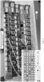
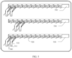
- FIG. 3 is a diagram according to this application.
- the splicing tray includes a plurality of ports. It may be considered that the plurality of ports are arranged in a form of a plurality of rows, and the plurality of ports are not aligned in a column direction.
- the plurality of ports may alternatively be arranged in a form of a plurality of columns.
- Quantities of ports in all columns may be the same or may be different, and ports in all columns may be aligned or may not be aligned in a row direction.
- the plurality of ports on the splicing tray may alternatively be arranged in a manner of unaligned in both a row direction and a column direction.
- An arrangement manner of the ports on the splicing tray is not specifically limited in this application.
- the splicing tray may be a splicing tray in the optical distribution frame, or may be a splicing tray in the optical cable cross-connect cabinet, or may be a splicing tray in another device. This is not limited in this application.
- a tray character label is disposed on the splicing tray, and the tray character label refers to a label on the splicing tray.
- the tray character label may be used to identify position information of each port of the splicing tray. A position of each port may be determined based on the tray character label.
- the tray character label may be, for example, a row label and/or a column label on the splicing tray. For example, in the example of FIG. 3 , ports in the rows are aligned in a row direction. Therefore, the row label may be set as a tray character label.
- row labels include A02, A03, A04, A05, and A06.
- a row label is used to identify a row position of each port.
- FIG. 3 row labels include A02, A03, A04, A05, and A06. A row label is used to identify a row position of each port.
- FIG. 3 row labels include A02, A03, A04, A05, and A06.
- a row label is used to identify
- a column position of a port may be determined based on a distance between the port and a row label of a row in which the port is located. In other words, the column position is a specific port (which may be calculated from left to right or from right to left) in the row.
- a row label may be located on a left side position of a row in which the row label is located, or may be located on a right side position of the row in which the row label is located, or a column label may be located on an upper side position of a column in which the column label is located, or may be located on a lower side position of the column in which the column label is located.
- a position of the tray character label is not specifically limited in this application. In this application, the tray character label including the row label and/or the column label is merely used as an example. The tray character label may alternatively be another form of label used to identify position information of each port. This is not limited in this application.
- the target image includes the plurality of ports on the splicing tray.
- the plurality of ports may be ports included in one row of the splicing tray, or may be ports included in a plurality of rows of the splicing tray, or may be ports included in one column of the splicing tray, or may be ports included in a plurality of columns of the splicing tray, or may be all ports on the splicing tray.
- the target image may be obtained by photographing one or more rows of ports on the splicing tray, or may be obtained by photographing one or more columns of ports on the splicing tray, or may be obtained by photographing all ports on the splicing tray.
- the target image includes the tray character label.
- the target image may include a row label of one row or row labels of a plurality of rows, or the target image includes a column label of one column or column labels of a plurality of columns.
- the target image should include a row label of the row during photographing; if the target image is obtained by photographing ports in a plurality of rows on the splicing tray, the target image should include row labels of the plurality of rows during photographing; if the target image is obtained by photographing ports in one column on the splicing tray, the target image should include a column label of the column during photographing; if the target image is obtained by photographing ports in a plurality of columns on the splicing tray, the target image should include column labels of the plurality of columns during photographing; or if the target image is obtained by photographing all ports on the splicing tray, the target image should include all tray character labels on the
- the target image may be obtained through photographing by the first vision sensor in any photographing posture, where the photographing posture includes a photographing height, a photographing distance, and a photographing direction.
- the photographing height is a photographing height of the first vision sensor, and the photographing height may use a horizontal ground as a reference object, or may use another object as a reference object.
- the photographing distance is a distance between the first vision sensor and the splicing tray.
- a distance between a specific point on the first vision sensor and a specific point on the splicing tray may be used as the photographing distance.
- a distance between a center of the first vision sensor and a center of the splicing tray is used as the photographing distance, or a distance between another specific point on the first vision sensor and another specific point on the splicing tray may be used as the photographing distance. This is not limited in this application.
- the photographing direction means to select a photographing point around a photographed object on a same horizontal plane with the photographed object as a center.
- different photographing directions may present different side images of the photographed object.
- images or videos of the photographed object obtained through photographing in different photographing directions are different.
- colors of the photographed object in obtained images or videos are relatively bright, and in some photographing directions, colors of the photographed object in obtained images or videos are relatively dark.
- zoom ratios or deformations of different parts of the photographed object in the obtained images or videos are different.
- the first vision sensor photographs the plurality of ports on the splicing tray in different photographing directions, and images of the plurality of ports in the obtained target images are also different.
- the first vision sensor when the first vision sensor photographs the plurality of ports on the splicing tray, the first vision sensor may perform photographing at a front angle, that is, the first vision sensor and the splicing tray are spaced at a specific distance, and perform photographing in a posture parallel to the splicing tray.
- the first vision sensor may perform photographing at a non-front angle, that is, not in a posture parallel to the splicing tray, and photograph the splicing tray at a specific tilt angle.
- the specific tilt angle means that the first vision sensor has a specific tilt angle relative to a plane parallel to the splicing tray.
- the tilt angle may be any one or a combination of a depression angle, an elevation angle, a left tilt angle, and a right tilt angle.
- the terminal device may be any terminal device described in the system in FIG. 1 , and has a function of the terminal device in the system in FIG. 1 .
- the first vision sensor may be located in the terminal device, and the terminal device controls the first vision sensor to capture the target image.
- the terminal device may be a mobile phone or a tablet computer, and the first vision sensor may be a camera on the mobile phone or the tablet computer.
- the first vision sensor may not be located on the terminal device.
- the first vision sensor may be a camera machine, and the terminal device may be a mobile phone or a tablet computer.
- the terminal device obtains the target image captured by the first vision sensor in a wired or wireless manner. The obtaining manner is not limited in this application.
- the terminal device determines a photographing posture of the first vision sensor based on a posture of the tray character label in the target image, and determines position information of each of the plurality of ports based on the photographing posture.
- the posture of the tray character label includes at least a position, a size, and a shape of the tray character label. Postures of the tray character label in the target image are different based on different photographing postures of the first vision sensor.
- the photographing posture of the first vision sensor includes a photographing height, a photographing distance, and a photographing direction. For example, when the first vision sensor is far from the splicing tray, that is, when the photographing distance is large, an image of the tray character label in the target image is small. When the first vision sensor is close to the splicing tray, that is, when the photographing distance is small, an image of the tray character label in the target image is large.
- the first vision sensor when the first vision sensor performs photographing in different photographing directions or at different photographing heights, images of the tray character label in the target image are also different, and postures of the tray character label are different.
- the first vision sensor performs photographing at a front angle, an image of the tray character label in the target image has no deformation.
- the first vision sensor performs photographing at a non-front angle, an image of the tray character label in the target image has a deformation, and a larger tilt angle of the first vision sensor indicates a larger image deformation of the tray character label in the target image.
- the tray character label on the splicing tray is rectangular, when photographing is performed at a specific tilt angle, the tray character label in the target image may be in a parallelogram; or when photographing is performed at a specific photographing height or in a specific photographing direction, the tray character label in the target image may be in a trapezoid.
- the photographing posture of the first vision sensor may be determined by performing calculation based on the posture of the tray character label in the target image by using an algorithm.
- the photographing posture of the first vision sensor may be represented by a vector.
- a photographing posture vector of the first vision sensor may be calculated based on the posture of the tray character label in the target image.
- the photographing distance, the photographing height, and the photographing direction may also be obtained based on the photographing posture vector.
- a method for determining the photographing posture of the first vision sensor based on the posture of the tray character label in the target image is not limited in this application.
- the terminal device may capture the target image by using the first vision sensor and determine the photographing posture of the first vision sensor based on the posture of the tray character label in the target image in an interleaving manner, and when the photographing posture of the first vision sensor does not meet a preset condition, the terminal device provides a prompt of adjusting the photographing posture.
- the terminal device captures an image or a video of the splicing tray, and the terminal device processes the obtained image or video, determines a photographing posture of the first vision sensor based on a posture of a tray character label in the obtained image or video, and when the photographing posture of the first vision sensor does not meet the preset condition, provides a prompt about how to adjust the photographing posture, for example, "the photographing distance is excessively long, and please adjust the photographing distance"; "the photographing height is excessively high, and please adjust the photographing height”; and “the photographing direction is excessively tilted, and please adjust the photographing direction”.
- the terminal device captures an image or a video of the splicing tray again.
- the preset condition is to impose a constraint on the photographing posture of the first vision sensor, for example, impose a constraint on one or more of the photographing height, the photographing distance, and the photographing direction.
- a range of the photographing distance may be limited.
- the photographing distance cannot exceed a threshold, or the photographing distance should be within a range between a threshold and another threshold.
- the photographing height and the photographing direction may affect a deformation degree of the tray character label in the target image. An excessive deformation causes difficulty in subsequent image processing, for example, difficulty in determining a photographing posture based on a posture of the tray character label in the target image. Therefore, constraints are imposed on the photographing height and the photographing direction, to facilitate subsequent image processing.
- the target image may be preprocessed first.
- the preprocessing includes image enhancement, that is, image enhancement is performed on the tray character label and each port in the target image, so that the image is clearer.
- the preprocessing may alternatively be another operation, for example, image denoising.
- the preprocessing operation is not limited in this application.
- the determining position information of each of the plurality of ports based on the photographing posture includes determining a row position and a column position of each port.
- ports on the splicing tray are aligned in a row direction and a column direction, that is, the ports may be considered to be arranged in a form of a square array.
- a row label and a column label are disposed on the splicing tray.
- row position information and column position information of each port are determined based on a row label, a column label, and a photographing posture (or a photographing posture vector) in the target image.
- ports on the splicing tray are aligned in a row direction, and a row label is disposed on the splicing tray.
- distances between adjacent ports in each row are equal or approximately equal.
- Column position information is determined based on a photographing posture and a distance between a port and a row label of a row in which the port is located, and row position information of each port may be determined based on the row label and the photographing posture.
- a specific column in which a port in a row is located may be obtained through calculation based on a distance between the port and a row label of the row in which the port is located, a photographing posture, and d.
- a specific algorithm is not limited in this application.
- the terminal device determines a status of each of the plurality of ports based on image data of the plurality of ports in the target image.
- the status of the port includes an idle state, an occupied state, and an unavailable state. That the port is in the unavailable state means that a flange that is of the port and that is configured to connect to an optical fiber patch cord falls off, where the flange refers to a metal body configured to connect to the optical fiber patch cord. That the port is in the occupied state means that the flange of the port is connected to the optical fiber patch cord. That the port is in the idle state means that the flange that is of the port and that is configured to connect to the optical fiber patch cord does not fall off and is not connected to the optical fiber patch cord. For example, in the example shown in FIG.
- FIG. 3 flanges that are configured to connect to optical fiber patch cords and that are of the 1 st port, the 3 rd port, the 5 th port, and the 6 th port that are counted from right to left in the row A03 fall off, and these ports are in an unavailable state; the 5 th port counted from right to left in the row A04, and the 5 th port and the 8 th port counted from right to left in the row A06 are all connected to optical fiber patch cords, and these ports are in an occupied state; and flanges of the 1 st port to the 8 th port counted from right to left in the row A02, and the 1 st port and the 2 nd port counted from right to left in the row A04 do not fall off and are not connected to optical fiber patch cords, and all these ports are in an idle state.
- FIG. 3 herein is merely used as an example, and does not constitute a limitation on this application.
- the status of each of the plurality of ports is determined based on the image data of the plurality of ports in the target image.
- the target image may be input into a trained first prediction model (the first prediction model corresponds to the prediction model in the claims), to obtain a status of each of the plurality of ports.
- the first prediction model is obtained through training based on a large quantity of image samples, each image sample includes at least one port and a label of each of the at least one port, and the label of each port is used to mark a status of the port.
- the trained first prediction model may be used to predict a status of each port.
- a specific training method used for the first prediction model is not limited in this application.
- Step S102 there is no sequence between step S102 and step S103.
- Step S103 may be performed before step S102. This is not limited in this application.
- the terminal device sends the position information of each of the plurality of ports and the corresponding status of each port to a system background.
- system background may be located on the server in the system in FIG. 1 .
- S105 The system background updates a historical status of each port based on the position information of each port and the corresponding status of each port.
- the terminal device sends the position information of each port in the target image and the corresponding status of each port to the system background.
- the system background stores the position information of each port and the historical status of each port. After receiving the status of each port sent by the terminal device, the system background updates the historical status based on the status of each port sent by the terminal device.
- the historical status of each port may be updated according to an on-site result respecting principle.
- Table 1 Historical status of a port in a system background Idle state Occupied state Unavailable state Status of the port determined based on a target image Idle state Consistent, and unchanged
- the status in the system background is updated to an idle state, and the historical status is temporarily stored in a database Inconsistent, and unchanged Occupied state
- the status in the system background is updated to an occupied state, and the historical status is temporarily stored in the database Consistent, and unchanged
- the status in the system background is updated to an occupied state, and the historical status is temporarily stored in the database Unavailable state
- the status in the system background is updated to an unavailable state
- the status in the system background is updated to an unavailable state, and the historical status is temporarily stored in the database Consistent, and unchanged
- the historical status in the system background may remain unchanged. Because the idle state is determined based on an appearance of the port to determine whether the port is undamaged, and whether a determining result is applicable is unknown in practice, and needs to be determined through measurement. That the historical status is the unavailable state indicates that the port may be unavailable. Therefore, in this case, keep the historical status in the system background unchanged.
- this application provides a data processing method.
- the terminal device captures the target image, where the target image includes the tray character label and the plurality of ports on the splicing tray.
- the terminal device determines position information of each port in the target image based on the posture of the tray character label, then determines the status of each port based on the image data of the plurality of ports, further sends the position information of each port and the corresponding status of each port to the system background, and updates the historical status of each port.
- the method in this application facilitates management, operation, and maintenance of optical network resources, saves human resources, and improves efficiency of management, operation, and maintenance.
- FIG. 4 is a schematic flowchart of a data processing method according to this application. The method includes but is not limited to descriptions of the following content.
- a terminal device obtains a target image captured by a first vision sensor, where the target image includes a tray character label and a plurality of ports on a splicing tray.
- step S101 in the embodiment in FIG. 2 .
- step S101 for this step, refer to the descriptions of content in step S101 in the embodiment in FIG. 2 .
- details are not described herein again.
- Identification information is set at both ends of the optical fiber patch cord, and a correspondence exists between the identification information at both ends of each optical fiber patch cord.
- the identification information may be, for example, any one or a combination of a two-dimensional code, a bar code, a specific character, or a specific pattern.
- the specific character may be, for example, A1, A2, B1, or B2, or may be &1, &2, *1, or *2.
- a specific form of the identification information is not limited in this application.
- the identification information is set before delivery, and the correspondence between the identification information is also determined before delivery and pre-stored in a system background. For example, if identification information A1 corresponds to identification information A2, and identification information on one end of an optical fiber patch cord is A1, identification information on the other end of the optical fiber patch cord is A2. If identification information &1 corresponds to identification information &2, and identification information on one end of an optical fiber patch cord is &1, identification information on the other end of the optical fiber patch cord is &2. Similarly, if identification information is a two-dimensional code, a bar code, a specific pattern, or the like, a correspondence also exists between identification information at both ends of an optical fiber patch cord.
- the optical fiber patch cord is connected to the port through a mechanical part, where the mechanical part is marked with identification information.
- the mechanical part is plugged into a port of the optical fiber patch cord, and the optical fiber patch cord is plugged into the port of the splicing tray through the mechanical part.
- FIG. 5 is a diagram of an example according to this application. In FIG.
- 510 is a mechanical part
- 511 is identification information on the mechanical part
- 540 is an optical fiber patch cord
- 520 is a port of a splicing tray
- 530 is a row label
- a first end of the mechanical part 510 is configured to be plugged into the optical fiber patch cord 540
- the optical fiber patch cord 540 is plugged into the port 520 of the splicing tray through the first end of the mechanical part 510
- a second end of the mechanical part 510 is marked with the identification information 511
- the identification information 511 may be two-dimensional code information
- the identification information may alternatively be other information.
- the splicing tray may include more or fewer ports.
- a structure and a form of the mechanical part in FIG. 5 are merely an example, and a specific structure and form of the mechanical part may alternatively be another form. This is not limited in this application.
- a port is connected to an optical fiber patch cord
- identification information is definitely set at two ends of the optical fiber patch cord
- the target image includes identification information of at least one end of the optical fiber patch cord.
- some ports of the plurality of ports on the splicing tray are connected to optical fiber patch cords, that is, some ports are in an occupied state.
- the method embodiment in FIG. 2 does not limit a manner for the optical fiber patch cords to connect to the ports.
- the optical fiber patch cords may be connected to the ports through mechanical parts, or may be directly connected to the ports. In the method embodiment in FIG. 2 , only whether the optical fiber patch cords are connected to the ports and whether the ports are damaged are described, and whether identification information is set on the optical fiber patch cords is not limited.
- the terminal device determines a port in an occupied state in the plurality of ports based on image data of the plurality of ports in the target image.
- a status of each of the plurality of ports may be first determined based on the image data of the plurality of ports in the target image, where the status of each port includes an occupied state, an idle state, and an unavailable state, and then the port in the occupied state is screened out.
- the occupied state, the idle state, the unavailable state, and the manner for determining the status of each of the plurality of ports refer to the descriptions of the content in step S103 in the embodiment in FIG. 2 .
- the target image is input into a second prediction model, to obtain the port in the occupied state in the plurality of ports.
- the second prediction model is obtained through training based on a large quantity of image samples, and each image sample includes at least one port in an occupied state.
- the target image is input into the second prediction model, and the second prediction model identifies each port in the target image, to identify the port in the occupied state.
- a specific training method used for the second prediction model is not limited in this application.
- the terminal device determines a photographing posture of the first vision sensor based on a posture of the tray character label in the target image, and determines position information of each of the port in the occupied state based on the photographing posture.
- the terminal device identifies identification information of an optical fiber patch cord connected to each of the port in the occupied state, to obtain an identification result.
- the terminal device sends the position information of each of the port in the occupied state and the corresponding identification result to the system background.
- the identification information may be a two-dimensional code, a bar code, a specific pattern, or the like.
- the terminal device identifies the identification information to obtain the identification result.
- the identification result may be a "code or name" of an optical fiber patch cord represented by the identification information, for example, the identification result may be A1, A2, &1, &2, *1, *2, or the like.
- the position information of each port in the occupied state and the identification result of the corresponding identification information to the system background.
- the identification information may be in a form of A1, A2, &1, &2, *1, *2, or the like, the identification information does not need to be identified, and the terminal device may directly send the position information of each port in the occupied state and the corresponding identification information to the system background.
- S206 The system background updates a connection relationship between the optical fiber patch cord and the port based on the position information of each port and the corresponding identification result.
- the system background receives the position information of each port in the occupied state and the corresponding identification result sent by the terminal device.
- the correspondence between identification information is pre-stored in the system background.
- A1 corresponds to A2
- B1 corresponds to B2
- &1 corresponds to &2
- *1 corresponds to *2.
- the system background stores historical information, and the historical information includes the connection relationship between the optical fiber patch cord and the port.
- the system background may determine information about each port based on the received position information of each port in the occupied state, and check the connection relationship between the optical fiber patch cord and the port in the historical information based on each port, the corresponding identification result, and the pre-stored correspondence between identification information.
- the information in the system background may be updated according to an on-site result respecting principle. For example, when the on-site determined result is consistent with the historical information result stored in the system background, the information remains unchanged. When the on-site determined result is inconsistent with the historical information result stored in the system background, the historical information in the system background is updated to the on-site determined result.
- the historical information may be temporarily stored in a database, and an error correction person may be dispatched to the site for check.
- the terminal device determines the position information of each port in the occupied state and the corresponding identification information of the optical fiber patch cord connected to each port, and sends the information to the system background.
- the system background checks and updates the connection relationship between the optical fiber patch cord and the port based on the information.
- the method in this application facilitates management, operation, and maintenance of optical network resources, improves efficiency of management, operation, and maintenance, and saves human resources.
- FIG. 6 is a schematic flowchart of a data processing method according to this application. The method includes but is not limited to descriptions of the following content.
- a terminal device obtains a target image captured by a first vision sensor, where the target image includes a tray character label and a plurality of ports on a splicing tray.
- some ports of the ports on the splicing tray are connected to optical fiber patch cords, and identification information is set on the optical fiber patch cords.
- identification information is set on the optical fiber patch cords.
- the terminal device determines a photographing posture of the first vision sensor based on a posture of the tray character label in the target image, and determines position information of each of the plurality of ports based on the photographing posture.
- the terminal device determines a status of each of the plurality of ports based on image data of the plurality of ports in the target image, where the status of each port includes an idle state, an occupied state, and an unavailable state.
- steps S302 and S303 refer to the descriptions in steps S102 and S103 in the method embodiment in FIG. 2 .
- steps S302 and S303 refer to the descriptions in steps S102 and S103 in the method embodiment in FIG. 2 .
- the terminal device identifies identification information of an optical fiber patch cord connected to each port in an occupied state, to obtain an identification result.
- the terminal device sends the position information of each port, the corresponding status of each port, and the identification result corresponding to the port in the occupied state to a system background.
- steps S304 and S305 refer to the descriptions in steps S204 and S205 in the method embodiment in FIG. 4 .
- steps S304 and S305 refer to the descriptions in steps S204 and S205 in the method embodiment in FIG. 4 .
- steps S304 and S305 refer to the descriptions in steps S204 and S205 in the method embodiment in FIG. 4 .
- details are not described herein again.
- S306 The system background updates a historical status of each port and a connection relationship between the optical fiber patch cord and the port based on the position information of each port, the corresponding status of each port, and the identification result corresponding to the port in the occupied state.
- FIG. 7 is a diagram of a structure of a data processing apparatus 700 according to this application.
- the apparatus 700 may be configured as the terminal device in the system in FIG. 1 , or may be configured as the terminal device in the method embodiment in FIG. 2 , FIG. 4 , or FIG. 6 .
- the apparatus 700 includes:
- the photographing posture includes a photographing height, a photographing distance, and a photographing direction of the first vision sensor
- the posture of the tray character label includes at least a position, a size, and a shape of the tray character label.
- the determining unit 702 is configured to input the target image into a trained prediction model, to obtain the statuses of the plurality of ports.
- the prediction model is obtained through training based on a large quantity of image samples, the image sample includes at least one port and a label of each of the at least one port, and the label is used to mark a status of the port.
- the plurality of ports include any one or a combination of ports included in one or more rows on the splicing tray, ports included in one or more columns on the splicing tray, and all ports on the splicing tray.
- the status of each port in the plurality ports includes an idle state, an occupied state, and an unavailable state.
- the unavailable state of the port means that a flange that is of the port and that is configured to connect to an optical fiber patch cord falls off
- the idle state of the port means that the flange of the port does not fall off and is not connected to the optical fiber patch cord
- the occupied state of the port means that the flange of the port is connected to the optical fiber patch cord.
- identification information is set at both ends of the optical fiber patch cord, and a correspondence exists between the identification information at both ends of the same optical fiber patch cord; and when a port in an occupied state exists in the plurality of ports, the target image includes identification information of one end or both ends of an optical fiber patch cord connected to the port in the occupied state.
- the communication unit 703 is further configured to send, to the system background, position information of the port in the occupied state in the plurality of ports and the identification information of the end of the optical fiber patch cord connected to the port in the occupied state, so that the system background determines a connection relationship between the optical fiber patch cord and the port based on a pre-stored correspondence between the identification information.
- the identification information includes any one or a combination of a two-dimensional code, a bar code, a specific character, and a specific pattern.
- the apparatus 700 further includes an identification unit 704.
- the identification unit 704 is configured to identify the identification information of the end of the optical fiber patch cord connected to the port in the occupied state, to obtain an identification result.
- the communication unit 703 is configured to send the position information of the port in the occupied state and the identification result to the system background, so that the system background determines the connection relationship between the optical fiber patch cord and the port based on the pre-stored correspondence between the identification information.
- the terminal device 800 may be configured as the terminal device in the method embodiment in FIG. 2 , FIG. 4 , or FIG. 6 .
- FIG. 8 is a diagram of a structure of the terminal device 800 according to this application.
- the terminal device 800 includes a processor 810, a communication interface 820, and a memory 830.
- the processor 810, the communication interface 820, and the memory 830 may be connected to each other through an internal bus 840, or may implement communication in another manner like wireless transmission.
- the memory 830 is configured to store program code, and the processor 810 controls execution of the program code, to perform the steps in the embodiment in FIG. 2 , FIG. 4 , or FIG. 6 .
- the memory 830 is configured to store program code, and the processor 810 controls execution of the program code, to perform the steps in the embodiment in FIG. 2 , FIG. 4 , or FIG. 6 .
- the memory 830 may include a volatile memory, for example, a RAM.
- the memory 830 may alternatively include a nonvolatile memory, for example, a ROM or a flash memory (flash memory).
- flash memory flash memory
- the memory 830 may alternatively include a combination of the foregoing types.
- the communication interface 820 may be a wired interface (for example, an Ethernet interface), may be an internal interface (for example, a high-speed serial computer extension bus (peripheral component interconnect express, PCIE) bus interface), the wired interface (for example, the Ethernet interface), or a wireless interface (for example, a cellular network interface or a wireless local area network interface), and is configured to communicate with another device or module.
- a wired interface for example, an Ethernet interface
- PCIE peripheral component interconnect express
- the processor 810, the communication interface 820, and the like in the terminal device 800 may implement functions of the devices in the foregoing method embodiments and/or various steps and methods implemented by the devices. For brevity, details are not described herein again.
- the communication unit 703 in the data processing apparatus 700 may be located in the communication interface 820 in the terminal device 800, and the obtaining unit 701, the determining unit 702, and the identification unit 704 in the data processing apparatus 700 may be located in the processor 810 in the terminal device 800.
- the terminal device 800 may further include a user interaction interface or a display (not shown in the figure).
- the user interaction interface or the display is used for interaction between a user and the terminal device 800, and the user interaction interface or the display is further configured to display an image or information.
- the terminal device 800 displays the target image through the user interaction interface or the display, or the terminal device 800 prompts, on the user interaction interface or the display, the user how to perform adjustment to obtain a better target image.
- FIG. 8 is only a possible implementation of embodiments of this application.
- the terminal device 800 may further include more or fewer components. This is not limited herein.
- content that is not shown or described in embodiments of this application refer to related descriptions in the foregoing method embodiments. Details are not described herein again.
- This application further provides a computer-readable storage medium, including computer program instructions.
- the computer program instructions When the computer program instructions are executed by a computer, the computer performs some or all of the steps described in the foregoing data processing method embodiments.
- This application further provides a computer program product, including program instructions.
- the program instructions When the program instructions are run on a computer, the computer is enabled to perform some or all of the steps described in the foregoing data processing method embodiments.
- All or some of the foregoing embodiments may be implemented by using software, hardware, or any combination thereof.
- software When software is used to implement the embodiments, all or a part of the embodiments may be implemented in a form of a computer program product.
- the computer program product may include code.
- the computer program product is read and executed by a computer, some or all steps of the method recorded in the foregoing method embodiments may be implemented.
- the computer may be a general-purpose computer, a dedicated computer, a computer network, or other programmable apparatuses.
- the computer instructions may be stored in a computer-readable storage medium, or may be transmitted from a computer-readable storage medium to another computer-readable storage medium.
- the computer instructions may be transmitted from a website, computer, server, or data center to another website, computer, server, or data center in a wired (for example, a coaxial cable, an optical fiber, or a digital subscriber line) or wireless (for example, infrared, radio, or microwave) manner.
- the computer-readable storage medium may be any usable medium accessible by the computer, or a data storage device, for example, a server or a data center, integrating one or more usable media.
- the usable medium may be a magnetic medium (for example, a floppy disk, a hard disk, or a magnetic tape), an optical medium, or a semiconductor medium.
- Sequence adjustment, combination, or deletion may be performed on steps in the method in embodiments of this application based on an actual requirement.
- the units in the apparatus in embodiments of this application may be divided, combined, or deleted based on the actual requirement.
Landscapes
- Physics & Mathematics (AREA)
- General Physics & Mathematics (AREA)
- Optics & Photonics (AREA)
- Engineering & Computer Science (AREA)
- Computing Systems (AREA)
- Electromagnetism (AREA)
- Computer Networks & Wireless Communication (AREA)
- Signal Processing (AREA)
- Mechanical Coupling Of Light Guides (AREA)
- User Interface Of Digital Computer (AREA)
- Information Transfer Between Computers (AREA)
Applications Claiming Priority (2)
| Application Number | Priority Date | Filing Date | Title |
|---|---|---|---|
| CN202210617439.3A CN117197791A (zh) | 2022-06-01 | 2022-06-01 | 一种数据处理方法、装置、设备及系统 |
| PCT/CN2023/089206 WO2023231625A1 (zh) | 2022-06-01 | 2023-04-19 | 一种数据处理方法、装置、设备及系统 |
Publications (2)
| Publication Number | Publication Date |
|---|---|
| EP4513451A1 true EP4513451A1 (de) | 2025-02-26 |
| EP4513451A4 EP4513451A4 (de) | 2025-07-30 |
Family
ID=88998497
Family Applications (1)
| Application Number | Title | Priority Date | Filing Date |
|---|---|---|---|
| EP23814811.8A Pending EP4513451A4 (de) | 2022-06-01 | 2023-04-19 | Datenverarbeitungsverfahren und -vorrichtung sowie vorrichtung und system |
Country Status (3)
| Country | Link |
|---|---|
| EP (1) | EP4513451A4 (de) |
| CN (1) | CN117197791A (de) |
| WO (1) | WO2023231625A1 (de) |
Family Cites Families (5)
| Publication number | Priority date | Publication date | Assignee | Title |
|---|---|---|---|---|
| US9870773B2 (en) * | 2014-11-11 | 2018-01-16 | Commscope, Inc. Of North Carolina | Multi-tier intelligent infrastructure management systems for communications systems and related equipment and methods |
| JP2020527752A (ja) * | 2017-07-19 | 2020-09-10 | ファイバー・マウンテン・インコーポレイテッド | ファイバーコネクタセンブリ |
| CN110163050B (zh) * | 2018-07-23 | 2022-09-27 | 腾讯科技(深圳)有限公司 | 一种视频处理方法及装置、终端设备、服务器及存储介质 |
| CN113077516B (zh) * | 2021-04-28 | 2024-02-23 | 深圳市人工智能与机器人研究院 | 一种位姿确定方法及相关设备 |
| CN114494833A (zh) * | 2022-01-26 | 2022-05-13 | 杭州东方通信软件技术有限公司 | 光缆交接箱的端口的状态识别方法及装置 |
-
2022
- 2022-06-01 CN CN202210617439.3A patent/CN117197791A/zh active Pending
-
2023
- 2023-04-19 WO PCT/CN2023/089206 patent/WO2023231625A1/zh not_active Ceased
- 2023-04-19 EP EP23814811.8A patent/EP4513451A4/de active Pending
Also Published As
| Publication number | Publication date |
|---|---|
| WO2023231625A1 (zh) | 2023-12-07 |
| EP4513451A4 (de) | 2025-07-30 |
| CN117197791A (zh) | 2023-12-08 |
Similar Documents
| Publication | Publication Date | Title |
|---|---|---|
| CN112581546B (zh) | 摄像头标定方法、装置、计算机设备和存储介质 | |
| CN111355941B (zh) | 图像颜色实时校正方法、装置和系统 | |
| WO2021208875A1 (zh) | 视觉检测方法和视觉检测装置 | |
| CN110968375B (zh) | 界面控制方法、装置、智能终端及计算机可读存储介质 | |
| CN114666473B (zh) | 耕地保护用视频监控方法、系统、终端及存储介质 | |
| CN108668086B (zh) | 自动对焦方法、装置、存储介质及终端 | |
| CN111896233B (zh) | 对比度测试方法、对比度测试设备及存储介质 | |
| US20220164952A1 (en) | Capture and Storage of Magnified Images | |
| CN116416701A (zh) | 一种巡检方法、巡检装置、电子设备及存储介质 | |
| CN116337412A (zh) | 屏幕检测方法、设备及存储介质 | |
| JP2020191086A (ja) | 計量メータ・設置機器情報管理システム、計量メータ・設置機器情報管理方法及び計量メータ・設置機器情報管理プログラム | |
| CN111062374A (zh) | 身份证信息的识别方法、装置、系统、设备及可读介质 | |
| CN113850103A (zh) | 信息处理方法、装置、设备及存储介质 | |
| CN104202448A (zh) | 一种解决移动终端摄像头拍照亮度不均的系统及其方法 | |
| CN114299503A (zh) | 车牌识别方法、装置、电子设备及存储介质 | |
| EP4336449A1 (de) | Markierungslochpositionierungsverfahren und -vorrichtung, montagevorrichtung und speichermedium | |
| EP4513451A1 (de) | Datenverarbeitungsverfahren und -vorrichtung sowie vorrichtung und system | |
| CN116993654B (zh) | 摄像头模组缺陷检测方法、装置、设备、存储介质及产品 | |
| CN117057996A (zh) | 光伏板图像的处理方法、装置、设备及介质 | |
| CN116626046A (zh) | 一种继电保护柜端子缺陷检测方法、系统、设备和介质 | |
| CN118368408B (zh) | 图像采集设备的检测方法、设备和存储介质 | |
| CN113610019A (zh) | 监控图像矫正窗口的调整方法及装置、存储介质 | |
| CN115249244B (zh) | 屏幕缺陷的检测方法、装置、设备及计算机可读存储介质 | |
| CN115695679B (zh) | 三联深度模组匹配方法和装置、移动终端、介质和芯片 | |
| CN109286798B (zh) | 一种投影屏幕的边框位置识别方法、系统及终端设备 |
Legal Events
| Date | Code | Title | Description |
|---|---|---|---|
| STAA | Information on the status of an ep patent application or granted ep patent |
Free format text: STATUS: THE INTERNATIONAL PUBLICATION HAS BEEN MADE |
|
| PUAI | Public reference made under article 153(3) epc to a published international application that has entered the european phase |
Free format text: ORIGINAL CODE: 0009012 |
|
| STAA | Information on the status of an ep patent application or granted ep patent |
Free format text: STATUS: REQUEST FOR EXAMINATION WAS MADE |
|
| 17P | Request for examination filed |
Effective date: 20241121 |
|
| AK | Designated contracting states |
Kind code of ref document: A1 Designated state(s): AL AT BE BG CH CY CZ DE DK EE ES FI FR GB GR HR HU IE IS IT LI LT LU LV MC ME MK MT NL NO PL PT RO RS SE SI SK SM TR |
|
| A4 | Supplementary search report drawn up and despatched |
Effective date: 20250626 |
|
| RIC1 | Information provided on ipc code assigned before grant |
Ipc: G06V 20/62 20220101AFI20250620BHEP Ipc: G02B 6/44 20060101ALI20250620BHEP |
|
| DAV | Request for validation of the european patent (deleted) | ||
| DAX | Request for extension of the european patent (deleted) |