EP4513441A2 - Automatisierte schnittplanung zur entfernung erkrankter bereiche - Google Patents
Automatisierte schnittplanung zur entfernung erkrankter bereiche Download PDFInfo
- Publication number
- EP4513441A2 EP4513441A2 EP25150629.1A EP25150629A EP4513441A2 EP 4513441 A2 EP4513441 A2 EP 4513441A2 EP 25150629 A EP25150629 A EP 25150629A EP 4513441 A2 EP4513441 A2 EP 4513441A2
- Authority
- EP
- European Patent Office
- Prior art keywords
- cutting
- model
- diseased region
- cutting surface
- relative
- Prior art date
- Legal status (The legal status is an assumption and is not a legal conclusion. Google has not performed a legal analysis and makes no representation as to the accuracy of the status listed.)
- Pending
Links
Images


Classifications
-
- G—PHYSICS
- G06—COMPUTING OR CALCULATING; COUNTING
- G06T—IMAGE DATA PROCESSING OR GENERATION, IN GENERAL
- G06T19/00—Manipulating 3D models or images for computer graphics
-
- A—HUMAN NECESSITIES
- A61—MEDICAL OR VETERINARY SCIENCE; HYGIENE
- A61B—DIAGNOSIS; SURGERY; IDENTIFICATION
- A61B34/00—Computer-aided surgery; Manipulators or robots specially adapted for use in surgery
- A61B34/10—Computer-aided planning, simulation or modelling of surgical operations
-
- A—HUMAN NECESSITIES
- A61—MEDICAL OR VETERINARY SCIENCE; HYGIENE
- A61B—DIAGNOSIS; SURGERY; IDENTIFICATION
- A61B34/00—Computer-aided surgery; Manipulators or robots specially adapted for use in surgery
- A61B34/20—Surgical navigation systems; Devices for tracking or guiding surgical instruments, e.g. for frameless stereotaxis
-
- A—HUMAN NECESSITIES
- A61—MEDICAL OR VETERINARY SCIENCE; HYGIENE
- A61B—DIAGNOSIS; SURGERY; IDENTIFICATION
- A61B34/00—Computer-aided surgery; Manipulators or robots specially adapted for use in surgery
- A61B34/70—Manipulators specially adapted for use in surgery
- A61B34/76—Manipulators having means for providing feel, e.g. force or tactile feedback
-
- G—PHYSICS
- G06—COMPUTING OR CALCULATING; COUNTING
- G06T—IMAGE DATA PROCESSING OR GENERATION, IN GENERAL
- G06T17/00—Three dimensional [3D] modelling, e.g. data description of 3D objects
- G06T17/30—Polynomial surface description
-
- G—PHYSICS
- G16—INFORMATION AND COMMUNICATION TECHNOLOGY [ICT] SPECIALLY ADAPTED FOR SPECIFIC APPLICATION FIELDS
- G16H—HEALTHCARE INFORMATICS, i.e. INFORMATION AND COMMUNICATION TECHNOLOGY [ICT] SPECIALLY ADAPTED FOR THE HANDLING OR PROCESSING OF MEDICAL OR HEALTHCARE DATA
- G16H20/00—ICT specially adapted for therapies or health-improving plans, e.g. for handling prescriptions, for steering therapy or for monitoring patient compliance
- G16H20/40—ICT specially adapted for therapies or health-improving plans, e.g. for handling prescriptions, for steering therapy or for monitoring patient compliance relating to mechanical, radiation or invasive therapies, e.g. surgery, laser therapy, dialysis or acupuncture
-
- G—PHYSICS
- G16—INFORMATION AND COMMUNICATION TECHNOLOGY [ICT] SPECIALLY ADAPTED FOR SPECIFIC APPLICATION FIELDS
- G16H—HEALTHCARE INFORMATICS, i.e. INFORMATION AND COMMUNICATION TECHNOLOGY [ICT] SPECIALLY ADAPTED FOR THE HANDLING OR PROCESSING OF MEDICAL OR HEALTHCARE DATA
- G16H50/00—ICT specially adapted for medical diagnosis, medical simulation or medical data mining; ICT specially adapted for detecting, monitoring or modelling epidemics or pandemics
- G16H50/50—ICT specially adapted for medical diagnosis, medical simulation or medical data mining; ICT specially adapted for detecting, monitoring or modelling epidemics or pandemics for simulation or modelling of medical disorders
-
- A—HUMAN NECESSITIES
- A61—MEDICAL OR VETERINARY SCIENCE; HYGIENE
- A61B—DIAGNOSIS; SURGERY; IDENTIFICATION
- A61B17/00—Surgical instruments, devices or methods
- A61B2017/00017—Electrical control of surgical instruments
- A61B2017/00203—Electrical control of surgical instruments with speech control or speech recognition
-
- A—HUMAN NECESSITIES
- A61—MEDICAL OR VETERINARY SCIENCE; HYGIENE
- A61B—DIAGNOSIS; SURGERY; IDENTIFICATION
- A61B17/00—Surgical instruments, devices or methods
- A61B2017/00017—Electrical control of surgical instruments
- A61B2017/00207—Electrical control of surgical instruments with hand gesture control or hand gesture recognition
-
- A—HUMAN NECESSITIES
- A61—MEDICAL OR VETERINARY SCIENCE; HYGIENE
- A61B—DIAGNOSIS; SURGERY; IDENTIFICATION
- A61B34/00—Computer-aided surgery; Manipulators or robots specially adapted for use in surgery
- A61B34/10—Computer-aided planning, simulation or modelling of surgical operations
- A61B2034/101—Computer-aided simulation of surgical operations
- A61B2034/105—Modelling of the patient, e.g. for ligaments or bones
-
- A—HUMAN NECESSITIES
- A61—MEDICAL OR VETERINARY SCIENCE; HYGIENE
- A61B—DIAGNOSIS; SURGERY; IDENTIFICATION
- A61B34/00—Computer-aided surgery; Manipulators or robots specially adapted for use in surgery
- A61B34/10—Computer-aided planning, simulation or modelling of surgical operations
- A61B2034/107—Visualisation of planned trajectories or target regions
-
- A—HUMAN NECESSITIES
- A61—MEDICAL OR VETERINARY SCIENCE; HYGIENE
- A61B—DIAGNOSIS; SURGERY; IDENTIFICATION
- A61B34/00—Computer-aided surgery; Manipulators or robots specially adapted for use in surgery
- A61B34/20—Surgical navigation systems; Devices for tracking or guiding surgical instruments, e.g. for frameless stereotaxis
- A61B2034/2046—Tracking techniques
- A61B2034/2048—Tracking techniques using an accelerometer or inertia sensor
-
- A—HUMAN NECESSITIES
- A61—MEDICAL OR VETERINARY SCIENCE; HYGIENE
- A61B—DIAGNOSIS; SURGERY; IDENTIFICATION
- A61B34/00—Computer-aided surgery; Manipulators or robots specially adapted for use in surgery
- A61B34/20—Surgical navigation systems; Devices for tracking or guiding surgical instruments, e.g. for frameless stereotaxis
- A61B2034/2046—Tracking techniques
- A61B2034/2051—Electromagnetic tracking systems
-
- A—HUMAN NECESSITIES
- A61—MEDICAL OR VETERINARY SCIENCE; HYGIENE
- A61B—DIAGNOSIS; SURGERY; IDENTIFICATION
- A61B34/00—Computer-aided surgery; Manipulators or robots specially adapted for use in surgery
- A61B34/20—Surgical navigation systems; Devices for tracking or guiding surgical instruments, e.g. for frameless stereotaxis
- A61B2034/2046—Tracking techniques
- A61B2034/2055—Optical tracking systems
-
- A—HUMAN NECESSITIES
- A61—MEDICAL OR VETERINARY SCIENCE; HYGIENE
- A61B—DIAGNOSIS; SURGERY; IDENTIFICATION
- A61B34/00—Computer-aided surgery; Manipulators or robots specially adapted for use in surgery
- A61B34/20—Surgical navigation systems; Devices for tracking or guiding surgical instruments, e.g. for frameless stereotaxis
- A61B2034/2046—Tracking techniques
- A61B2034/2059—Mechanical position encoders
-
- A—HUMAN NECESSITIES
- A61—MEDICAL OR VETERINARY SCIENCE; HYGIENE
- A61B—DIAGNOSIS; SURGERY; IDENTIFICATION
- A61B34/00—Computer-aided surgery; Manipulators or robots specially adapted for use in surgery
- A61B34/20—Surgical navigation systems; Devices for tracking or guiding surgical instruments, e.g. for frameless stereotaxis
- A61B2034/2046—Tracking techniques
- A61B2034/2063—Acoustic tracking systems, e.g. using ultrasound
-
- A—HUMAN NECESSITIES
- A61—MEDICAL OR VETERINARY SCIENCE; HYGIENE
- A61B—DIAGNOSIS; SURGERY; IDENTIFICATION
- A61B34/00—Computer-aided surgery; Manipulators or robots specially adapted for use in surgery
- A61B34/20—Surgical navigation systems; Devices for tracking or guiding surgical instruments, e.g. for frameless stereotaxis
- A61B2034/2046—Tracking techniques
- A61B2034/2065—Tracking using image or pattern recognition
-
- A—HUMAN NECESSITIES
- A61—MEDICAL OR VETERINARY SCIENCE; HYGIENE
- A61B—DIAGNOSIS; SURGERY; IDENTIFICATION
- A61B34/00—Computer-aided surgery; Manipulators or robots specially adapted for use in surgery
- A61B34/20—Surgical navigation systems; Devices for tracking or guiding surgical instruments, e.g. for frameless stereotaxis
- A61B2034/2068—Surgical navigation systems; Devices for tracking or guiding surgical instruments, e.g. for frameless stereotaxis using pointers, e.g. pointers having reference marks for determining coordinates of body points
-
- A—HUMAN NECESSITIES
- A61—MEDICAL OR VETERINARY SCIENCE; HYGIENE
- A61B—DIAGNOSIS; SURGERY; IDENTIFICATION
- A61B90/00—Instruments, implements or accessories specially adapted for surgery or diagnosis and not covered by any of the groups A61B1/00 - A61B50/00, e.g. for luxation treatment or for protecting wound edges
- A61B90/06—Measuring instruments not otherwise provided for
- A61B2090/064—Measuring instruments not otherwise provided for for measuring force, pressure or mechanical tension
- A61B2090/065—Measuring instruments not otherwise provided for for measuring force, pressure or mechanical tension for measuring contact or contact pressure
-
- A—HUMAN NECESSITIES
- A61—MEDICAL OR VETERINARY SCIENCE; HYGIENE
- A61B—DIAGNOSIS; SURGERY; IDENTIFICATION
- A61B90/00—Instruments, implements or accessories specially adapted for surgery or diagnosis and not covered by any of the groups A61B1/00 - A61B50/00, e.g. for luxation treatment or for protecting wound edges
- A61B90/39—Markers, e.g. radio-opaque or breast lesions markers
- A61B2090/3937—Visible markers
- A61B2090/3945—Active visible markers, e.g. light emitting diodes
-
- A—HUMAN NECESSITIES
- A61—MEDICAL OR VETERINARY SCIENCE; HYGIENE
- A61B—DIAGNOSIS; SURGERY; IDENTIFICATION
- A61B90/00—Instruments, implements or accessories specially adapted for surgery or diagnosis and not covered by any of the groups A61B1/00 - A61B50/00, e.g. for luxation treatment or for protecting wound edges
- A61B90/39—Markers, e.g. radio-opaque or breast lesions markers
- A61B2090/3966—Radiopaque markers visible in an X-ray image
-
- A—HUMAN NECESSITIES
- A61—MEDICAL OR VETERINARY SCIENCE; HYGIENE
- A61B—DIAGNOSIS; SURGERY; IDENTIFICATION
- A61B34/00—Computer-aided surgery; Manipulators or robots specially adapted for use in surgery
- A61B34/30—Surgical robots
-
- G—PHYSICS
- G06—COMPUTING OR CALCULATING; COUNTING
- G06T—IMAGE DATA PROCESSING OR GENERATION, IN GENERAL
- G06T2210/00—Indexing scheme for image generation or computer graphics
- G06T2210/12—Bounding box
-
- G—PHYSICS
- G06—COMPUTING OR CALCULATING; COUNTING
- G06T—IMAGE DATA PROCESSING OR GENERATION, IN GENERAL
- G06T2210/00—Indexing scheme for image generation or computer graphics
- G06T2210/41—Medical
-
- G—PHYSICS
- G06—COMPUTING OR CALCULATING; COUNTING
- G06T—IMAGE DATA PROCESSING OR GENERATION, IN GENERAL
- G06T2219/00—Indexing scheme for manipulating 3D models or images for computer graphics
- G06T2219/008—Cut plane or projection plane definition
Definitions
- the subject disclosure relates to systems, methods, programs, and techniques for automated generation of surgical cutting plans for removing diseased regions of an anatomy, such as bone tumors.
- a standard practice is to surgically remove malignant bone tumors with the lesion intact (remaining in one piece) to ensure no tumor cells remain which can cause local recurrence.
- a primary aim of excision or resection remains achieving tumor free margins, even at the expense of sacrificing some function of the limb (in the form of removing additional healthy bone).
- the definition of surgical margins of surrounding healthy tissue and subsequent planning of cutting planes are important steps in these procedures. Margin definition depends on several factors, including the size and position of the tumor, presence of skip or secondary lesions, and the infiltration of the tumor through multiple anatomical compartments (for example beyond the growth plates or into soft tissue).
- a computer-implemented method for automated planning of a cutting boundary for removal of a diseased region of an anatomy.
- the method utilizes a model of the diseased region and the computer-implemented method comprising: defining, relative to the model, a first plane and a second plane being spaced apart from the first plane; identifying a geometrical feature of the model; providing a first reference spline derived from the geometrical feature onto the first plane; providing a second reference spline derived from the geometrical feature onto the second plane; creating a first set of ruled surfaces extending between the reference splines; optimizing a shape of one or both of the reference splines to thereby define one or both of an optimized first spline and an optimized second spline, wherein optimizing is based on minimizing a volume bounded by the first set of ruled surfaces and the first and second planes; creating a second set of ruled surfaces extending between one of the reference splines and one of the optimized
- a computer-implemented method for automated planning of a cutting boundary for removal of a diseased region of an anatomy, the method utilizing a model of the diseased region and a healthy region of the anatomy and utilizing a cutting surface defining a region to be removed from the anatomy, the computer-implemented method comprising: placing the cutting surface relative to the model of the diseased region; executing an optimization algorithm comprising: specifying an optimization criterion that minimizes an amount of healthy region to be removed by the cutting surface; initializing, relative to the cutting surface, candidate solutions influencing characteristics of the cutting surface; and iteratively performing the following sub-steps (1) to (3) until the candidate solution is identified that satisfies the optimization criterion: (1) evaluating fitness of each of the candidate solution relative to the optimization criterion; (2) identifying, among the candidate solutions, the candidate solution best fit to the optimization criterion; and (3) updating, relative to the cutting surface, the candidate solutions based on the candidate solution best fit to the optimization criterion;
- Some implementations comprise the geometrical feature being a contour of the diseased region, or an outermost contour of the diseased region. Some implementations comprise: providing one or both reference splines to have a contour being proportionally similar to and proportionally larger than the outermost contour. Some implementations comprise: identifying the geometrical feature to be a closed-loop contour; and providing the first and second reference splines to be closed-loop contours.
- the anatomy (A) model is generated based, in part or in whole, on statistical models or atlas data.
- the model (M) can generated, modified, and/or segmented using machine learning, such as a neural networks trained to specific populations.
- the model (M) can also be generated using imageless techniques, shown at 208, wherein a tracked probe or digitizer is intraoperatively utilized to obtain landmarks of the anatomy (A).
- the model (M) can be represented as a mesh of polygonal elements (e.g., triangles) or a NURBS surface. Any other technique for generating the model (M) of the anatomy (A) is contemplated.
- the cutting boundaries (CB) can be keep-in zones for keeping the tool within the boundary, keep-out zones for keeping the tool outside of a boundary, planar cut boundaries for keeping the tool on a planar cut path, and/or tool path boundaries for keeping the tool on a certain tool path.
- the cutting boundaries (CB) can be used to facilitate a complex cutting shapes, including corner cuts.
- the techniques herein can automatically optimize characteristics of the one or more cutting boundaries (CB) relative to the diseased region (DR) based on a plurality of inputs, constraints, criterion or parameters, which we refer to as planning constraints, shown at 212.
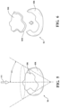
- One such constraint is en bloc removal, shown at 214 in FIG. 1 and visually represented in FIG. 6 . This is a cutting criterion requiring that the one or more cutting boundaries (CB) be planned for removal of an entirety of the diseased region (DR) as a single piece (en bloc) so as to prevent local recurrence.
- Intact removal of the complete diseased region (DR) may be implemented by constraints on the cutting boundary (CB) definition, such as requirements that the cutting boundary (CB) remain external to a surface of the diseased region (DR) without overlap and/or the cutting boundary (CB) fit be optimized to the to the surface of the diseased region (DR) as a whole, without division of the diseased region (DR).
- CB cutting boundary
- Additional planning constraints can be considered, such as requirements that the cutting boundary (CB) be accessed with respect to a defined approach direction or axis (AA), shown at 216 in FIG. 1 and visually represented in FIG. 5 .
- the approach axis (AA) defines the planned primary approach for the surgeon to access the surgical site with a cutting tool.
- the approach direction or axis (AA) can be defined based on surgeon preference or can be determined (or optimized) based on automated techniques evaluating the position, orientation, and/or size of the model (M) of the diseased region (DR), e.g., relative to other features of the anatomy or limitations of the tool.
- the z-axis of the coordinate system in which the model (M) is located can be aligned to the approach axis (AA).
- the x or y-axis of the coordinate system in which the model (M) is located can be aligned to the approach axis (AA).
- an angle of access can also be inputted as a constraint into the optimization algorithm.
- the angle of access (A ⁇ ) represents the degree of access to the surgical site desired or required to treat the tissue.
- An access angle (A ⁇ ) of 0° limits the cutting direction to exactly along the access direction (i.e. as a cut out of the tumor) with greater angles meaning that the tool orientation can vary up to the desired value from the access direction (AA).
- the approach axis (AA) and access angle (A ⁇ ) can be understood as a three-dimensional representation, e.g., as a conical volume containing the diseased region (DR) whereby the axis of the cone is defined by the approach axis (AA) and the aperture of the cone is defined by the access angle (A ⁇ ).
- the pose of the cutting boundary (CB) can be limited to an angle, or range of angles, to respect the limited access dictated by the approach axis (AA) and/or angle of access.
- an addition requirement that can affect automated planning of the cutting boundary (CB) is that the cutting boundary (CB) does not pass through defined critical or no-go regions (N) or zones of the anatomy (A). Such regions are those beyond the diseased region (DR) and located in the healthy region (HR), which should be avoided by the cutting boundary (CB) to prevent removal of the critical structure.
- Such features include, but are not limited to nerves, vessels, articulating joint surfaces, ligaments or ligament insertions, tendons, and the like. These features can be imaged, segmented, and modeled to be included in the model (M) of the anatomy.
- the planning methods can position, orient, size and/or shape the cutting boundaries (CB) to avoid these regions.
- CB cutting boundary
- planning can also be constrained, as shown at 222, such that no cutting boundary (CB) intersects itself in the planning phase.
- Self-intersection can be addressed by proactively avoiding self-intersections or by allowing the self-intersection and removing portions of the cutting boundary (CB) that self-intersect. Additional examples of self-intersection are provided below.
- resection or surgical margin can also be inputted as a constraint on the automated planning techniques described herein.
- a margin (RM) as understood with respect to removal of malignant bone tumors, is the margin of non-tumorous tissue around the diseased region (DR) that has been surgically removed.
- the margin (RM) is described as negative when no cancer cells are present at the edge of the tissue, suggesting that all of the cancer has been removed.
- the margin (RM) is described as positive when cancer cells are present at the edge of the tissue, suggesting that all of the cancer has not been removed.
- the margin (RM) can be set based on surgical preferences, imaging data, default settings, tool geometry, and the like.
- the margin (RM) can be: greater than 0 and less than 1mm; greater than 5mm and less than 10mm, or any other margin that is appropriate for the given procedure or patient condition.
- the defined margins (RM) can affect how the cutting boundary (CB) is oriented or sized relative to the diseased region (DR).
- the margin (RM) can be uniform or variable in dimension.
- the techniques herein automatically optimize characteristics of the one or more cutting geometries (C) relative to the diseased region (DR).
- One manner by which optimization is performed is shown at 228, and described in detail below, which is an optimization criterion requiring minimization of an amount of healthy region (HR) to be removed by the one or more cutting boundaries (CB) so as to keep as much of the healthy bone in tact after excision or resection.
- the minimization of healthy region (HR) does not necessarily mean total minimization such that no healthy region (HR) is removed.
- the amount of healthy region (HR) removed can depend on many factors, such as the presence or absence of other constraints on planning, such as en bloc removal 214, access direction (AA), access angle (A ⁇ ), avoiding critical regions 220, avoiding self-intersection 222, and the definition of surgical margins (RM).
- Another planning constraint may be a requirement that removed region can be filled, e.g., either with an implant or a bone reconstruction material.
- the cutting boundary (CB) is defined such that the planning phase is largely complete.
- a clinical application 186 which can comprise the non-transitory memory storing the instructions for implementing the described automated planning techniques, the surgeon may be able to define, activate, or deactivate any of the parameters, inputs or criterion described above. The surgeon can also modify the optimized cutting boundary (CB) after its generation.
- the automated planning methods can be performed preoperatively or intraoperatively.
- the automated planning methods may be implemented using any appropriate artificial intelligence or machine learning algorithms, including but not limited to any one or more of the following: supervised, unsupervised or reinforcement learning algorithms, neural networks, convolutional neural networks, support vector machining, Bayesian networks, K means prediction, Gaussian mixture models, Dirchlet processes, Q-learning, R-learning, TD learning, Random Forest, dimensionally reduction algorithms, gradient boosting algorithms, linear or logistic regression, k-nearest neighbors, k-means, evolutionary algorithms, genetic algorithms, particle swarm algorithms, or any combination thereof, or the like.
- supervised, unsupervised or reinforcement learning algorithms neural networks, convolutional neural networks, support vector machining, Bayesian networks
- K means prediction, Gaussian mixture models, Dirchlet processes, Q-learning, R-learning, TD learning, Random Forest, dimensionally reduction algorithms, gradient boosting algorithms, linear or logistic regression, k-nearest neighbors, k-means, evolutionary algorithms, genetic algorithms, particle swarm algorithms, or any combination thereof, or the like.
- the automated planning technique creates a first set of ruled surfaces (RS1) extending between the reference splines (S1, S2).
- automated optimization of a shape of one or both of the reference splines (S1, S2) is performed to thereby define one or both of an optimized first spline (OS1) and an optimized second spline (OS2).
- optimizing is based on minimizing a volume bounded by the first set of ruled surfaces (RS1) and the first and second planes (P1, P2).
- a viewing angle is set as the line of intersection between a pair of cutting surfaces (CS), then, with respect to the selected viewing angle, the relative alignment of each cutting surface (CS) is determined.
- the algorithm moves to the next pair of cutting surfaces (CS), and performs the same checks with respect to the new viewing angle. If a particular viewing angle results in each remaining cutting surface (CS) having a negative relative z normal value, then no cutting surface (CS) occludes the resection, and the candidate solution is viable.
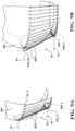
- FIGS. 20A-20C One example of a process of checking whether the resection plan geometry is viable is shown in FIGS. 20A-20C , illustrating an example with three 2D projections of a resection plan with four cutting surfaces (CS1-CS4).
- the bone model (M) surface and volume points are projected in two dimensions and include the diseased region (DR) and the planned portion of healthy region (HR) to be removed. Each view is aligned with the line of intersection between a pair of cutting surfaces (CS).
- Cutting surfaces (CS) are shown with the corresponding normal vector.
- FIG. 20A and 20B show that the resection plan cannot be removed along the corresponding projection.
- cutting surface (CS2) is occluding (shown in the FIGS. 20A-20C by shading) the resection with normal vector pointing towards the viewing angle.
- the cutting surface (CS4) is slightly occluding the resection.
- FIG. 20C shows a projection in which the resection can be removed, as no cutting surface (CS) normal vector points 'toward' the viewing angle.
- a surgical system 100 comprising a robotic manipulator 102 supporting a tool 104 is shown.
- the surgical system 100 is useful for treating an anatomical volume or target site TS of a patient's P body B, such as bone or soft tissue.
- the manipulator 102 generally comprises a base 106, a robotic arm 108, and a coupling 110.
- the robotic arm 108 is supported by the base 106 and is configured to move, maintain, or otherwise control the position and/or orientation of the coupling 110 relative to the base 106 during use.
- the coupling 110 is adapted to releasably secure one or more types of tools 104 which, in turn, generally support or otherwise include an instrument 112 utilized in connection with various types of surgical procedures.
- the instrument 112 may be configured to support, drive, rotate, oscillate, vibrate, and/or otherwise direct energy to an energy applicator 114 (e.g., drill bits, taps, burs, router, end mill, blades, saws, reamers, lasers, and the like) used to effect treatment at or adjacent to the target site TS.
- the end effector can also be a surgical cutting guide, such one comprising slots for guiding a hand-held saw on a cutting plane.
- the instrument 112 may be configured to support, position, align, and/or guide implantable components 116 (e.g., cups, stems, screws, pins, rods, wires, anchors, prostheses, and the like) at or with respect to the target site TS, such as along a trajectory T maintained by the manipulator 102.
- implantable components 116 e.g., cups, stems, screws, pins, rods, wires, anchors, prostheses, and the like
- the patient P is undergoing an illustrative surgical procedure where the target site TS includes or is otherwise defined by portions of the patient's hip and femur.
- various types of surgical procedures are contemplated by the present disclosure, including without limitation surgical procedures involving bone tumor resection, partial or total knee or hip replacement surgery, shoulder replacement surgery, spine surgery, ankle surgery, and the like.
- the surgical procedure may involve tissue removal or other forms of treatment (e.g., cutting, drilling, reaming, coagulating, lesioning, other in-situ tissue treatments, and the like).
- the surgical system 100 may be designed to facilitate cutting away material to be replaced by implantable components 116 (also referred to as "implants"), such as hip and knee implants, including unicompartmental, bicompartmental, multicompartmental, or total knee implants.
- implantable components 116 also referred to as "implants”
- hip and knee implants including unicompartmental, bicompartmental, multicompartmental, or total knee implants.
- other configurations are contemplated, and the surgical system 100 could be utilized in connection with a number of different surgical procedures and may employ various types, styles, and configurations of manipulators 102, tools 104, instruments 112, energy applicators 114, and/or implantable components 116 without departing from the scope of the present disclosure.
- the surgical system 100 and techniques disclosed herein may be used to perform other procedures, surgical or non-surgical, or may be used in industrial applications or other applications where robotic systems are utilized.
- the manipulator 102 (also referred to as a "surgical robot") moves the tool 104 relative to the target site TS and relative to the base 106 via the robotic arm 108 to, among other things, assist medical professionals in carrying out various types of surgical procedures with precise control over movement and positioning of the tool 104, the instrument 112, the energy applicator 114, and/or the implantable component 116.
- the manipulator 102 generally comprises the base 106, the robotic arm 108, and the coupling 110.
- the base 106 is fixed to a manipulator cart 118 and supports the robotic arm 108 which, in turn, is configured to move, maintain, or otherwise control the position and/or orientation of the coupling 110 relative to the base 106 during use.
- the robotic arm 108 illustrated in Figure 21 comprises a plurality of links 120 and joints J arranged in a serial arm configuration.
- the manipulator 102 could employ a different configuration without departing from the scope of the present disclosure.
- the manipulator 102 may have a parallel arm configuration, or any other suitable configuration. In some embodiments, more than one manipulator 102 may be utilized in a multiple arm configuration. It will be appreciated that the robotic arm 108 and other portions of the manipulator 102 may be arranged in a number of different configurations without departing from the scope of the present disclosure.
- the manipulator 102 comprises a plurality of joint encoders 122 located at the joints J for determining position data of the joints J.
- the robotic arm 108 has six joints J1, J2, J3, J4, J5, J6 implementing at least six degrees of freedom (DOF) for the manipulator 102.
- the manipulator 102 may have any suitable number of degrees of freedom, may have any suitable number of joints J, and may have redundant joints J.
- the manipulator 102 need not require joint encoders 122 but may alternatively, or additionally, utilize motor encoders present on motors at each joint J.
- the manipulator 102 need not require rotary joints, but may alternatively, or additionally, utilize one or more prismatic joints. Any suitable combination of joint types are contemplated.
- the surgical system 100 is able to monitor, track, and/or determine changes in the relative position and/or orientation of one or more parts of the manipulator 102, the robotic arm 108, the tool 104, the instrument 112, the energy applicator 114, and/or the implantable component 116, as well as various parts of the patient's body B, within a common coordinate system by utilizing various types of trackers (e.g., multiple degree-of-freedom optical, inertial, and/or ultrasonic sensing devices), navigation systems (e.g., machine vision systems, charge coupled device cameras, tracker sensors, surface scanners, and/or range finders), anatomical computer models (e.g., magnetic resonance imaging scans of the patient's P anatomy), data from previous surgical procedures and/or previously-performed surgical techniques (e.g., data recorded during prior steps of the surgical procedure), and the like.
- trackers e.g., multiple degree-of-freedom optical, inertial, and/or ultrasonic sensing devices
- navigation systems e
- the surgical system 100 employs a control system 124 (also referred to as a "controller” 124) which may comprise or otherwise communicate with one or more of a robotic control system 126, a navigation system 128, and a tool control system 130 which cooperate to facilitate positioning, moving, and/or driving the tool 104 relative to the target site TS and other parts of the surgical system 100 via the manipulator 102, as described in greater detail below.
- a control system 124 also referred to as a "controller” 124
- a robotic control system 126 may comprise or otherwise communicate with one or more of a robotic control system 126, a navigation system 128, and a tool control system 130 which cooperate to facilitate positioning, moving, and/or driving the tool 104 relative to the target site TS and other parts of the surgical system 100 via the manipulator 102, as described in greater detail below.
- the base 106 generally provides a fixed reference coordinate system for other components of the manipulator 102 and/or other components of the surgical system 100.
- the origin of a manipulator coordinate system MNPL is defined at the fixed reference of the base 106.
- the base 106 may be defined with respect to any suitable portion of the manipulator 102, such as one or more of the links 120.
- the base 106 may be defined with respect to the manipulator cart 118, such as where the manipulator 102 is physically attached to the cart 118.
- the base 106 is defined at an intersection of the axis of joint J1 and the axis of joint J2.
- the robotic control system 126, the navigation system 128, and/or the tool control system 130 may also comprise, define, or otherwise employ a user interface 142 with one or more output devices 144 (e.g., screens, displays, status indicators, and the like) and/or input devices 146 (e.g., push button, keyboard, mouse, microphone, voice-activation devices, gesture control devices, touchscreens, foot pedals, pendants, and the like). Other configurations are contemplated.
- output devices 144 e.g., screens, displays, status indicators, and the like
- input devices 146 e.g., push button, keyboard, mouse, microphone, voice-activation devices, gesture control devices, touchscreens, foot pedals, pendants, and the like.
- Other configurations are contemplated.
- first tool tracker 160G and the second tool tracker 160I depicted in Figure 21 can be used by the navigation system 128 to readily determine the relative positions and/or orientations of different parts of the tool 104 via the localizer 158, certain embodiments of the present disclosure may be configured to facilitate this determination in other ways (e.g., such as with one or more sensors).
- other configurations are contemplated by the present disclosure, and it will be appreciated that various combinations of trackers 160, sensors, predetermined geometric relationships, and the like can be utilized in order to track certain objects or otherwise relate those objects to a tracked object.
- first tool tracker 160G and/or the second tool tracker 160I could be fixed to portions of the tool 104 in various ways, such as by integration during manufacture or by releasable attachment ahead of or during a surgical procedure.
- various trackers 160 may be firmly affixed to different types of tracked objects (e.g., discrete bones, tools, pointers, and the like) in a number of different ways.
- trackers 160 may be rigidly fixed, flexibly connected (optical fiber), or not physically connected at all (ultrasound), as long as there is a suitable (e.g., supplemental) way to determine the relationship (e.g., measurement) of that respective tracker 160 to the object or anatomy that it is associated with.
- the position and/or orientation of the trackers 160 relative to the objects or anatomy to which they are attached can be determined by utilizing known registration techniques. For example, determining the pose of the patient trackers 160A, 160B relative to the portions of the patient's body B to which they are attached can be accomplished with various forms of point-based registration, such as where a distal tip of the pointer 156 is used to engage against specific anatomical landmarks (e.g., touching specific portions of bone) or is used to engage several parts of a bone for surface-based registration as the localizer 158 monitors the position and orientation of the pointer tracker 160P. Conventional registration techniques can then be employed to correlate the pose of the patient trackers 160A, 160B to the patient's anatomy (e.g., to each of the femur and the acetabulum).
- point-based registration such as where a distal tip of the pointer 156 is used to engage against specific anatomical landmarks (e.g., touching specific portions of bone) or is used to engage several parts of a
- the manipulator controller 132 and the tool controller 136 are operatively attached to the base 106 of the manipulator 102, and the navigation controller 134 and the localizer 158 are supported on a mobile cart 164 which is movable relative to the base 106 of the manipulator 102.
- the mobile cart 164 may also support the user interface 142 to facilitate operation of the surgical system 100 by displaying information to, and/or by receiving information from, the surgeon or another user. While shown as a part of the navigation system 128 in the representative embodiment illustrated in Figure 21 , it will be appreciated that the user interface 142 could form part of, or otherwise communicate with, other parts of the control system 124 such as the robotic control system 126 and/or the tool control system 130.
- the user interface 142 may be disposed in communication with navigation controller 134, the manipulator controller 132, and/or the tool controller 136, and may likewise comprise one or more output devices 144 (e.g., monitors, indicators, display screens, and the like) to present information to the surgeon or other users (e.g., images, video, data, graphics, navigable menus, and the like), and one or more input devices 146 (e.g., physical or virtual input controls, buttons, touch screens, keyboards, mice, gesture or voice-based input devices, and the like).
- output devices 144 e.g., monitors, indicators, display screens, and the like
- input devices 146 e.g., physical or virtual input controls, buttons, touch screens, keyboards, mice, gesture or voice-based input devices, and the like.
- one or more portions of the surgical system 100 are generally configured to transform the coordinates of each tracker 160 sensed via the localizer 158 from the localizer coordinate system LCLZ into the manipulator coordinate system MNPL (or to other coordinate systems), or vice versa, so that articulation of the manipulator 102 can be performed based at least partially on the relative positions and/or orientations of certain trackers 160 within a common coordinate system (e.g., the manipulator coordinate system MNPL, the localizer coordinate system LCLZ, or another common coordinate system).
- a common coordinate system e.g., the manipulator coordinate system MNPL, the localizer coordinate system LCLZ, or another common coordinate system.
- coordinates within the localizer coordinate system LCLZ can be transformed into coordinates within the manipulator coordinate system MNPL (or other coordinate systems), and vice versa, using a number of different transformation techniques.
- the localizer 158 is an optical localizer and includes a camera unit 166 with one or more optical sensors 168 and, in some embodiments, a video camera 170.
- the localizer 158 may also comprise a localizer controller (not shown) which communicates with the navigation controller 134 or otherwise forms part of the navigation system 128.
- the navigation system 128 employs the optical sensors 168 of the camera unit 166 to sense the position and/or orientation of the trackers 160 within the localizer coordinate system LCLZ.
- the trackers 160 each employ a plurality of markers 162 (see Figure 21 ) which can be sensed by the optical sensors 168 of the camera unit 166.
- the markers 162 are active markers (e.g., light emitting diodes "LEDs") which emit light that can be sensed by the localizer 158.
- the trackers 160 may employ passive markers (e.g., reflectors) which reflect light emitted from the localizer 158 or another light source.
- the navigation system 128 could have any suitable configuration for monitoring trackers 160 which, as will be appreciated from the subsequent description below, may be of various types and configurations.
- the navigation system 128 may comprise multiple localizers 158 and/or trackers 160 of the same or different type.
- the software programs and/or modules include computer readable instructions stored in non-transitory memory 140 on the manipulator controller 132, the navigation controller 134, the tool controller 136, or a combination thereof, to be executed by one or more processors 138 of one or more of the controllers 136, 132, 134.
- the non-transitory memory 140 can store the instructions for implementing the above described automated planning techniques.
- the memory 140 may be of any suitable configuration, such as random access memory (RAM) , non-volatile memory, and the like, and may be implemented locally or from a remote location (e.g., a database, a server, and the like). Additionally, software modules for prompting and/or communicating with the user may form part of the modules or programs, and may include instructions stored in memory 140 on the manipulator controller 132, the navigation controller 134, the tool controller 136, or any combination thereof. The user may interact with any of the input devices 146 and/or output devices 144 of any of the user interfaces 142 (e.g., the user interface 142 of the navigation system 128 shown in Figure 22 ) to communicate with the software modules and/or programs.
- RAM random access memory
- non-volatile memory and the like
- software modules for prompting and/or communicating with the user may form part of the modules or programs, and may include instructions stored in memory 140 on the manipulator controller 132, the navigation controller 134, the tool controller 136, or any combination thereof.
- the control system 124 may also comprise user interfaces 142 (e.g., a graphical user interface GUI) or other software or modules that could run on a separate device from the manipulator controller 132, the navigation controller 134, and/or the tool controller 136 (e.g., a portable electronic device such as a tablet computer). Other configurations are contemplated.
- user interfaces 142 e.g., a graphical user interface GUI
- other software or modules that could run on a separate device from the manipulator controller 132, the navigation controller 134, and/or the tool controller 136 (e.g., a portable electronic device such as a tablet computer).
- Other configurations are contemplated.
- the control system 124 may comprise any suitable arrangement and/or configuration of input, output, and processing devices suitable for carrying out the functions and methods described herein.
- the surgical system 100 may comprise the manipulator controller 132, the navigation controller 134, or the tool controller 136, or any combination thereof, or may comprise only some of these controllers, or additional controllers, any of which could form part of the control system 124 as noted above.
- the controllers 132, 134, 136 may communicate via a wired bus or communication network as shown in Figure 22 , via wireless communication, or otherwise.
- the control system 124 may also be referred to as a controller, and may likewise comprise one or more microcontrollers, field programmable gate arrays, systems on a chip, discrete circuitry, sensors, displays, user interfaces, indicators, and/or other suitable hardware, software, or firmware that is capable of carrying out the functions described herein. Other configurations are contemplated.
- the software employed by the control system 124 may include a boundary generator 172.
- the boundary generator 172 is a software program or module that generates a virtual boundary 174 for constraining movement and/or operation of the tool 104.
- the virtual boundary 174 is the cutting boundary (CB) generated from the above-described planning techniques.
- the virtual boundary 174 may be one-dimensional, two-dimensional, or three-dimensional, and may comprise a point, line, axis, trajectory, plane, or other shapes, including complex geometric shapes.
- the virtual boundary 174 is a surface defined by a triangle mesh. Such virtual boundaries 174 may also be referred to as virtual objects.
- the virtual boundaries 174 may be defined with respect to an anatomical model AM, such as a three-dimensional bone model.
- the anatomical model Am is associated with the real anatomy of the patient P by virtue of the anatomical model AM being mapped to the anatomy of the patient P via registration or other processes.
- the virtual boundaries 174 comprises a generally spherical mesh substantially surrounding an acetabulum with an entry portion (e.g., an opening) that provides access to the acetabulum.
- the entry portion has a funnel or conical shape.
- the virtual boundary 174 is associated with a three-dimensional model of the acetabulum of the pelvis.
- a path generator 176 is another software program or module that may be run by the control system 124. In some embodiments, the path generator 176 is run by the manipulator controller 132. The path generator 176 generates a tool path TP for the tool 104 to traverse, such as for removing sections of the anatomy of the patient P at the target site TS to receive an implantable component 116.
- the tool path TP may comprise a plurality of path segments PS, or may comprise a single path segment PS.
- the path segments PS may be straight segments, curved segments, combinations thereof, and the like.
- the tool path TP may also be defined with respect to the anatomical model AM.
- the tool path TP may be implant-specific (e.g., defined based on a size, shape, volume, and the like of an implantable component 116) and/or patient-specific (e.g., defined based on the anatomy of the patient P). Other configurations are contemplated.
- the tool path TP is defined as a tissue removal path adjacent to the target site TS.
- the tool path TP may be used for treatment other than tissue removal.
- One example of the tissue removal path described herein comprises a tool path TP.
- the term "tool path" generally refers to the path of the tool 104 in the vicinity of the target site TS for milling the anatomy, and is not intended to require that the tool 104 be operably milling the anatomy throughout the entire duration of the path.
- the tool path TP may comprise sections or segments where the tool 104 transitions from one location to another without milling.
- other forms of tissue removal along the tool path TP may be employed, such as tissue ablation, and the like.
- the tool path TP may be a predefined path that is created pre-operatively, intra-operatively, or combinations thereof.
- the tool path TP may be defined before the surgical procedure begins, during the surgical procedure (including during tissue removal), or combinations thereof.
- the control system 124 obtains the tool path TP by storing/retrieving the tool path TP in/from memory 140, obtaining the tool path TP from memory 140, creating the tool path TP pre-operatively, creating the tool path TP intra-operatively, and the like.
- the tool path TP may have any suitable shape, or combinations of shapes, such as circular, helical/corkscrew, linear, curvilinear, combinations thereof, and the like. Other configurations are contemplated.
- the virtual boundaries 174 and/or the milling paths MP may be generated offline rather than on the manipulator controller 132, navigation controller 134, or another component of the surgical system 100. Thereafter, the virtual boundaries 174 and/or milling paths MP may be utilized at runtime by the manipulator controller 132.
- Behavior control 178 is the process of computing data that indicates the next commanded position and/or orientation (e.g., pose) for the tool 104. In some cases, only the position or orientation of the tool center point TCP is output from the behavior control 178, while in other cases, the position and the orientation of the tool center point TCP is output from the behavior control 178.
- output from the boundary generator 172, the path generator 176, and a sensor 180 may feed as inputs into the behavior control 178 to determine the next commanded position and/or orientation for the tool 104.
- the behavior control 178 may process these inputs, along with one or more virtual constraints as described in greater detail below, to determine a commanded pose CP.
- motion control 182 is the control of the manipulator 102.
- the motion control 182 receives data defining the next commanded pose from the behavior control 178. Based on these data, the motion control 182 determines the next position of the joint angles of the joints J of the robotic arm 108 of the manipulator 102 (e.g., via inverse kinematics and Jacobian calculators) so that the manipulator 102 is able to position the tool 104 as commanded by the behavior control 178 (e.g., at the commanded pose).
- the motion control 182 processes the commanded pose CP, which may be defined in Cartesian space, into joint angles of the manipulator 102, so that the manipulator controller 132 can command the joint motors accordingly in order to move the joints J of the manipulator 102 to commanded joint angles corresponding to the commanded pose of the tool 104.
- the motion control 182 regulates the joint angle of each joint J of the robotic arm 108 and continually adjusts the torque that each joint motor outputs in order to, as closely as possible, ensure that the joint motor drives the associated joint J to the commanded joint angle.
- the boundary generator 172, the path generator 176, the behavior control 178, and the motion control 182 may be sub-sets (e.g., modules) of a software program 184. Alternatively, each may be a software program that operates separately and/or independently, or any combination thereof.
- the term "software program” is used herein to describe the computer-executable instructions that are configured to carry out the various capabilities of the technical solutions described. For simplicity, the term "software program” is intended to encompass, at least, any one or more of the boundary generator 172, the path generator 176, the behavior control 178, and/or the motion control 182.
- the software program 184 can be implemented on the manipulator controller 132, navigation controller 134, or any combination thereof, or may be implemented in any suitable manner by the control system 124.
- the clinical application 186 interfaces with the boundary generator 172 and/or path generator 176 after implant placement is set by the user, and then sends the virtual boundary 174 and/or the tool path TP returned by the boundary generator 172 and/or the path generator 176 to the manipulator controller 132 for execution.
- the manipulator controller 132 executes the tool path TP as described herein.
- the manipulator controller 132 may additionally create certain segments (e.g., lead-in segments) when starting or resuming machining to smoothly get back to the generated tool path TP.
- the manipulator controller 132 may also process the virtual boundaries 174 to generate corresponding virtual constraints as described in greater detail below.
- the surgical system 100 may operate in a manual mode.
- the user manually directs, and the manipulator 102 executes movement of the tool 104 and its energy applicator 114 at the surgical site.
- the user e.g., the surgeon
- the manipulator 102 monitors forces and torques placed on the tool 104 by the user in order to position the tool 104.
- measurements taken by the sensor 180 are transformed from a sensor coordinate system SN of the sensor 180 to another coordinate system, such as a virtual mass coordinate system VM, in which a virtual simulation VS is carried out on a virtual rigid body VRB model of the tool 104 so that the forces and torques can be virtually applied to the virtual rigid body VRB in the virtual simulation VS to ultimately determine how those forces and torques (among other inputs) would affect movement of the virtual rigid body VRB, as described below.
- a virtual simulation VS is carried out on a virtual rigid body VRB model of the tool 104 so that the forces and torques can be virtually applied to the virtual rigid body VRB in the virtual simulation VS to ultimately determine how those forces and torques (among other inputs) would affect movement of the virtual rigid body VRB, as described below.
- the surgical system 100 may also operate in a semi-autonomous mode in which the manipulator 102 autonomously moves the tool 104 along the tool path TP, such as by operating active joints J of the manipulator 102 to move the tool 104 without requiring force/torque on the tool 104 from the user.
- the manipulator 102 when the manipulator 102 operates in the semi-autonomous mode, the manipulator 102 is capable of moving the tool 104 free of user assistance.
- free of user assistance may mean that the user does not physically contact the tool 104 or the robotic arm 108 to move the tool 104.
- the user may use some form of remote control (e.g., a pendant; not shown) to control starting and stopping of movement. For example, the user may hold down a button of the remote control to start movement of the tool 104 and release the button to stop movement of the tool 104.
- Other configurations are contemplated.
Landscapes
- Health & Medical Sciences (AREA)
- Engineering & Computer Science (AREA)
- Surgery (AREA)
- Life Sciences & Earth Sciences (AREA)
- Public Health (AREA)
- Medical Informatics (AREA)
- General Health & Medical Sciences (AREA)
- Nuclear Medicine, Radiotherapy & Molecular Imaging (AREA)
- Biomedical Technology (AREA)
- Robotics (AREA)
- Animal Behavior & Ethology (AREA)
- Molecular Biology (AREA)
- Heart & Thoracic Surgery (AREA)
- Veterinary Medicine (AREA)
- Physics & Mathematics (AREA)
- General Physics & Mathematics (AREA)
- Primary Health Care (AREA)
- Epidemiology (AREA)
- Theoretical Computer Science (AREA)
- Computer Graphics (AREA)
- Software Systems (AREA)
- Urology & Nephrology (AREA)
- Data Mining & Analysis (AREA)
- Databases & Information Systems (AREA)
- Pathology (AREA)
- Mathematical Analysis (AREA)
- Algebra (AREA)
- General Engineering & Computer Science (AREA)
- Mathematical Optimization (AREA)
- Mathematical Physics (AREA)
- Pure & Applied Mathematics (AREA)
- Geometry (AREA)
- Computer Hardware Design (AREA)
- Apparatus For Radiation Diagnosis (AREA)
- Surgical Instruments (AREA)
- Magnetic Resonance Imaging Apparatus (AREA)
Applications Claiming Priority (2)
| Application Number | Priority Date | Filing Date | Title |
|---|---|---|---|
| US202062990038P | 2020-03-16 | 2020-03-16 | |
| EP21162700.5A EP3886056B1 (de) | 2020-03-16 | 2021-03-15 | Automatisierte schnittplanung zum entfernen von erkrankten bereichen |
Related Parent Applications (2)
| Application Number | Title | Priority Date | Filing Date |
|---|---|---|---|
| EP21162700.5A Division EP3886056B1 (de) | 2020-03-16 | 2021-03-15 | Automatisierte schnittplanung zum entfernen von erkrankten bereichen |
| EP21162700.5A Division-Into EP3886056B1 (de) | 2020-03-16 | 2021-03-15 | Automatisierte schnittplanung zum entfernen von erkrankten bereichen |
Publications (2)
| Publication Number | Publication Date |
|---|---|
| EP4513441A2 true EP4513441A2 (de) | 2025-02-26 |
| EP4513441A3 EP4513441A3 (de) | 2025-05-14 |
Family
ID=74874783
Family Applications (2)
| Application Number | Title | Priority Date | Filing Date |
|---|---|---|---|
| EP25150629.1A Pending EP4513441A3 (de) | 2020-03-16 | 2021-03-15 | Automatisierte schnittplanung zur entfernung erkrankter bereiche |
| EP21162700.5A Active EP3886056B1 (de) | 2020-03-16 | 2021-03-15 | Automatisierte schnittplanung zum entfernen von erkrankten bereichen |
Family Applications After (1)
| Application Number | Title | Priority Date | Filing Date |
|---|---|---|---|
| EP21162700.5A Active EP3886056B1 (de) | 2020-03-16 | 2021-03-15 | Automatisierte schnittplanung zum entfernen von erkrankten bereichen |
Country Status (3)
| Country | Link |
|---|---|
| US (2) | US11793574B2 (de) |
| EP (2) | EP4513441A3 (de) |
| AU (1) | AU2021201644A1 (de) |
Families Citing this family (19)
| Publication number | Priority date | Publication date | Assignee | Title |
|---|---|---|---|---|
| AU2018383641B2 (en) | 2017-12-14 | 2023-06-15 | Mako Surgical Corp. | View angle-independent visual representation of a cut procedure |
| EP4513441A3 (de) | 2020-03-16 | 2025-05-14 | Stryker Australia PTY LTD | Automatisierte schnittplanung zur entfernung erkrankter bereiche |
| EP4011312B1 (de) * | 2020-12-10 | 2023-08-23 | DePuy Ireland Unlimited Company | Robotisches chirurgisches system |
| CN117580526A (zh) * | 2021-07-20 | 2024-02-20 | 微创骨科学控股股份有限公司 | 用于使用摄影测量来创建用于矫形手术的患者专用引导件的系统和方法 |
| EP4152339A1 (de) * | 2021-09-20 | 2023-03-22 | Universität Zürich | Verfahren zur bestimmung eines operationsplans mittels eines verstärkungslernverfahrens |
| CN113768628B (zh) * | 2021-09-27 | 2023-12-12 | 武汉联影智融医疗科技有限公司 | 磨骨量安全范围确定方法和电子装置 |
| JP2025503621A (ja) * | 2022-01-06 | 2025-02-04 | モノグラム・オーサピディクス・インコーポレイテッド | 動的切断境界のデータ最適化方法 |
| EP4245242A1 (de) | 2022-03-18 | 2023-09-20 | Stryker Australia PTY LTD | Knochenresektionsbewertung und -planung |
| CN114913124B (zh) * | 2022-04-13 | 2023-04-07 | 中南大学湘雅医院 | 一种用于肿瘤手术的切缘路径生成方法、系统及存储介质 |
| WO2023237074A1 (zh) * | 2022-06-09 | 2023-12-14 | 上海市胸科医院 | 基于超声定位的结节定位方法、装置和电子设备 |
| WO2024006451A1 (en) * | 2022-06-30 | 2024-01-04 | Mako Surgical Corp. | Robotic surgery system with plan-dependent surgical visualization |
| US11547486B1 (en) | 2022-08-03 | 2023-01-10 | Ix Innovation Llc | Digital image analysis for robotic installation of surgical implants |
| WO2024039796A1 (en) * | 2022-08-19 | 2024-02-22 | Method Ai, Inc. | Surgical procedure segmentation |
| CN116851856B (zh) * | 2023-03-27 | 2024-05-10 | 浙江万能弹簧机械有限公司 | 纯水线切割加工工艺及其系统 |
| CN116807611A (zh) * | 2023-05-24 | 2023-09-29 | 安徽医科大学 | 一种基于差分进化算法的柔性穿刺针路径规划方法 |
| WO2025101785A1 (en) * | 2023-11-09 | 2025-05-15 | Mako Surgical Corp. | System and method for generating a patient-specific milling path |
| US20250255579A1 (en) * | 2024-02-08 | 2025-08-14 | Fujifilm Sonosite, Inc. | Repeatable Ultrasound |
| WO2025248507A1 (en) * | 2024-05-31 | 2025-12-04 | Stryker European Operations Limited | Extension of virtual models for surgical navigation |
| CN119837634B (zh) * | 2025-01-24 | 2025-09-16 | 北京天智航医疗科技股份有限公司 | 一种用于手术中脊柱锥体自动截骨的装置及其控制方法 |
Family Cites Families (39)
| Publication number | Priority date | Publication date | Assignee | Title |
|---|---|---|---|---|
| US20010034530A1 (en) | 2000-01-27 | 2001-10-25 | Malackowski Donald W. | Surgery system |
| US20040068187A1 (en) | 2000-04-07 | 2004-04-08 | Krause Norman M. | Computer-aided orthopedic surgery |
| US6711432B1 (en) | 2000-10-23 | 2004-03-23 | Carnegie Mellon University | Computer-aided orthopedic surgery |
| US8010180B2 (en) | 2002-03-06 | 2011-08-30 | Mako Surgical Corp. | Haptic guidance system and method |
| US7831292B2 (en) | 2002-03-06 | 2010-11-09 | Mako Surgical Corp. | Guidance system and method for surgical procedures with improved feedback |
| US7542791B2 (en) | 2003-01-30 | 2009-06-02 | Medtronic Navigation, Inc. | Method and apparatus for preplanning a surgical procedure |
| US7203277B2 (en) | 2003-04-25 | 2007-04-10 | Brainlab Ag | Visualization device and method for combined patient and object image data |
| JP2007518484A (ja) | 2004-01-19 | 2007-07-12 | コーニンクレッカ フィリップス エレクトロニクス エヌ ヴィ | 変形可能な表面のセグメント化のリアルタイムなユーザ対話処理 |
| TWI268148B (en) | 2004-11-25 | 2006-12-11 | Univ Chung Yuan Christian | Image analysis method for vertebral disease which comprises 3D reconstruction method and characteristic identification method of unaligned transversal slices |
| CA2580445A1 (en) | 2004-11-27 | 2006-06-01 | Bracco Imaging S.P.A. | 2d / 3d integrated contour editor |
| EP1871267B1 (de) | 2005-02-22 | 2018-09-12 | Mako Surgical Corp. | System zur haptischen führung |
| GB0504172D0 (en) | 2005-03-01 | 2005-04-06 | King S College London | Surgical planning |
| EP2001411B1 (de) | 2006-03-17 | 2013-05-01 | Zimmer, Inc. | Verfahren zur vorabfestlegung der kontur einer herausgeschnittenen knochenoberfläche und zur überprüfung des sitzes einer prothese auf dem knochen |
| RU2449372C2 (ru) | 2006-07-17 | 2012-04-27 | Конинклейке Филипс Электроникс, Н.В. | Эффективное взаимодействие пользователя с многоугольными сетками для сегментации медицинских изображений |
| US20090149977A1 (en) | 2007-11-06 | 2009-06-11 | Schendel Stephen A | Methods, systems, and computer program products for shaping medical implants directly from virtual reality models |
| US9364291B2 (en) | 2008-12-11 | 2016-06-14 | Mako Surgical Corp. | Implant planning using areas representing cartilage |
| EP2400927A2 (de) | 2009-02-24 | 2012-01-04 | Mako Surgical Corp. | Prothesenvorrichtung, verfahren zur planung der entfernung von knochen zur implantation der prothesenvorrichtung und robotersystem |
| US8675939B2 (en) | 2010-07-13 | 2014-03-18 | Stryker Leibinger Gmbh & Co. Kg | Registration of anatomical data sets |
| US9715754B2 (en) | 2010-08-05 | 2017-07-25 | Koninklijke Philips N.V. | In-plane and interactive surface mesh adaptation |
| US9119655B2 (en) | 2012-08-03 | 2015-09-01 | Stryker Corporation | Surgical manipulator capable of controlling a surgical instrument in multiple modes |
| US10667870B2 (en) * | 2011-02-17 | 2020-06-02 | The Trustees Of Dartmouth College | Systems and methods for guiding tissue resection |
| US9028499B2 (en) | 2011-02-23 | 2015-05-12 | The Regents Of The University Of California | Bone cutting device |
| US9381085B2 (en) | 2011-06-23 | 2016-07-05 | Stryker Corporation | Prosthetic implant and method of implantation |
| US8477153B2 (en) | 2011-08-24 | 2013-07-02 | General Electric Company | Method and system for navigating, segmenting, and extracting a three-dimensional image |
| WO2013033566A1 (en) | 2011-09-02 | 2013-03-07 | Stryker Corporation | Surgical instrument including a cutting accessory extending from a housing and actuators that establish the position of the cutting accessory relative to the housing |
| WO2013101753A1 (en) | 2011-12-30 | 2013-07-04 | Mako Surgical Corp. | Systems and methods for customizing interactive haptic boundaries |
| CA2873224A1 (en) | 2012-04-06 | 2013-10-10 | Conformis, Inc. | Advanced methods, techniques, devices, and systems for cruciate retaining knee implants |
| US9008757B2 (en) | 2012-09-26 | 2015-04-14 | Stryker Corporation | Navigation system including optical and non-optical sensors |
| EP2967589B1 (de) | 2013-03-15 | 2019-04-24 | Stryker Corporation | Endeffektor eines chirurgischen manipulationsroboters |
| KR102335667B1 (ko) | 2013-12-31 | 2021-12-03 | 마코 서지컬 코포레이션 | 커스터마이징된 햅틱 경계를 생성하기 위한 시스템 및 방법 |
| US20160256279A1 (en) | 2015-03-02 | 2016-09-08 | Union College | Patient-Specific Implant for Bone Defects and Methods for Designing and Fabricating Such Implants |
| US10117713B2 (en) | 2015-07-01 | 2018-11-06 | Mako Surgical Corp. | Robotic systems and methods for controlling a tool removing material from a workpiece |
| CN108430375B (zh) | 2015-11-11 | 2021-05-07 | 马科外科公司 | 机器人系统以及反向驱动该系统的方法 |
| US10433921B2 (en) | 2015-12-28 | 2019-10-08 | Mako Surgical Corp. | Apparatus and methods for robot assisted bone treatment |
| AU2019211450B2 (en) | 2018-01-26 | 2024-10-24 | Mako Surgical Corp. | End effectors and methods for driving tools guided by surgical robotic systems |
| US10679350B2 (en) | 2018-08-10 | 2020-06-09 | Koninklijke Philips N.V | Method and apparatus for adjusting a model of an anatomical structure |
| US20200170604A1 (en) | 2018-12-04 | 2020-06-04 | Howmedica Osteonics Corp. | CT Based Probabilistic Cancerous Bone Region Detection |
| US11547482B2 (en) | 2018-12-13 | 2023-01-10 | Mako Surgical Corp. | Techniques for patient-specific morphing of virtual boundaries |
| EP4513441A3 (de) | 2020-03-16 | 2025-05-14 | Stryker Australia PTY LTD | Automatisierte schnittplanung zur entfernung erkrankter bereiche |
-
2021
- 2021-03-15 EP EP25150629.1A patent/EP4513441A3/de active Pending
- 2021-03-15 EP EP21162700.5A patent/EP3886056B1/de active Active
- 2021-03-15 US US17/201,479 patent/US11793574B2/en active Active
- 2021-03-16 AU AU2021201644A patent/AU2021201644A1/en active Pending
-
2023
- 2023-09-14 US US18/368,044 patent/US12193755B2/en active Active
Also Published As
| Publication number | Publication date |
|---|---|
| US12193755B2 (en) | 2025-01-14 |
| US20230414291A1 (en) | 2023-12-28 |
| EP4513441A3 (de) | 2025-05-14 |
| US11793574B2 (en) | 2023-10-24 |
| EP3886056B1 (de) | 2025-04-02 |
| AU2021201644A1 (en) | 2021-09-30 |
| US20210282858A1 (en) | 2021-09-16 |
| EP3886056A1 (de) | 2021-09-29 |
Similar Documents
| Publication | Publication Date | Title |
|---|---|---|
| US12193755B2 (en) | Automated cut planning for removal of diseased regions | |
| US12232827B2 (en) | Techniques for patient-specific milling path generation | |
| US11648679B2 (en) | Techniques for controlling position of an end effector of a robotic device relative to a virtual constraint | |
| US12059211B2 (en) | Techniques for patient-specific morphing of virtual boundaries | |
| EP4248900B1 (de) | System zur chirurgischen planung mit weichgewebebefestigungspunkten | |
| US20170231704A1 (en) | Systems and methods for selectively activating virtual guide geometries | |
| US20230190378A1 (en) | Robotic Systems, Methods And Software Programs For Modifying Tool Operation Based On Tissue Parameters | |
| US12528184B2 (en) | Robotic systems and methods for mitigating undesired orientational motion of kinematic components | |
| US20230329813A1 (en) | Systems And Methods For Guided Placement Of A Robotic Manipulator | |
| EP4645327A1 (de) | Verfahren zur erzeugung von fremdkörperextraktionsplänen | |
| KR102926626B1 (ko) | 가상 경계의 환자별 모핑을 위한 기술 | |
| US20250152266A1 (en) | System And Method For Generating A Patient-Specific Milling Path |
Legal Events
| Date | Code | Title | Description |
|---|---|---|---|
| PUAI | Public reference made under article 153(3) epc to a published international application that has entered the european phase |
Free format text: ORIGINAL CODE: 0009012 |
|
| STAA | Information on the status of an ep patent application or granted ep patent |
Free format text: STATUS: THE APPLICATION HAS BEEN PUBLISHED |
|
| AC | Divisional application: reference to earlier application |
Ref document number: 3886056 Country of ref document: EP Kind code of ref document: P |
|
| AK | Designated contracting states |
Kind code of ref document: A2 Designated state(s): AL AT BE BG CH CY CZ DE DK EE ES FI FR GB GR HR HU IE IS IT LI LT LU LV MC MK MT NL NO PL PT RO RS SE SI SK SM TR |
|
| PUAL | Search report despatched |
Free format text: ORIGINAL CODE: 0009013 |
|
| AK | Designated contracting states |
Kind code of ref document: A3 Designated state(s): AL AT BE BG CH CY CZ DE DK EE ES FI FR GB GR HR HU IE IS IT LI LT LU LV MC MK MT NL NO PL PT RO RS SE SI SK SM TR |
|
| RIC1 | Information provided on ipc code assigned before grant |
Ipc: A61B 34/10 20160101ALI20250407BHEP Ipc: G06T 17/30 20060101ALI20250407BHEP Ipc: G06T 19/00 20110101AFI20250407BHEP |
|
| STAA | Information on the status of an ep patent application or granted ep patent |
Free format text: STATUS: REQUEST FOR EXAMINATION WAS MADE |
|
| 17P | Request for examination filed |
Effective date: 20251114 |