EP4513244A2 - Telekommunikationstafel - Google Patents
Telekommunikationstafel Download PDFInfo
- Publication number
- EP4513244A2 EP4513244A2 EP24209536.2A EP24209536A EP4513244A2 EP 4513244 A2 EP4513244 A2 EP 4513244A2 EP 24209536 A EP24209536 A EP 24209536A EP 4513244 A2 EP4513244 A2 EP 4513244A2
- Authority
- EP
- European Patent Office
- Prior art keywords
- basket
- tray
- cable
- telecommunications
- retention
- Prior art date
- Legal status (The legal status is an assumption and is not a legal conclusion. Google has not performed a legal analysis and makes no representation as to the accuracy of the status listed.)
- Pending
Links
Images




Classifications
-
- G—PHYSICS
- G02—OPTICS
- G02B—OPTICAL ELEMENTS, SYSTEMS OR APPARATUS
- G02B6/00—Light guides; Structural details of arrangements comprising light guides and other optical elements, e.g. couplings
- G02B6/44—Mechanical structures for providing tensile strength and external protection for fibres, e.g. optical transmission cables
- G02B6/4439—Auxiliary devices
- G02B6/444—Systems or boxes with surplus lengths
- G02B6/4453—Cassettes
- G02B6/4455—Cassettes characterised by the way of extraction or insertion of the cassette in the distribution frame, e.g. pivoting, sliding, rotating or gliding
-
- G—PHYSICS
- G02—OPTICS
- G02B—OPTICAL ELEMENTS, SYSTEMS OR APPARATUS
- G02B6/00—Light guides; Structural details of arrangements comprising light guides and other optical elements, e.g. couplings
- G02B6/44—Mechanical structures for providing tensile strength and external protection for fibres, e.g. optical transmission cables
- G02B6/4439—Auxiliary devices
- G02B6/444—Systems or boxes with surplus lengths
- G02B6/4452—Distribution frames
- G02B6/44526—Panels or rackmounts covering a whole width of the frame or rack
-
- G—PHYSICS
- G02—OPTICS
- G02B—OPTICAL ELEMENTS, SYSTEMS OR APPARATUS
- G02B6/00—Light guides; Structural details of arrangements comprising light guides and other optical elements, e.g. couplings
- G02B6/44—Mechanical structures for providing tensile strength and external protection for fibres, e.g. optical transmission cables
- G02B6/4439—Auxiliary devices
- G02B6/444—Systems or boxes with surplus lengths
- G02B6/44528—Patch-cords; Connector arrangements in the system or in the box
-
- G—PHYSICS
- G02—OPTICS
- G02B—OPTICAL ELEMENTS, SYSTEMS OR APPARATUS
- G02B6/00—Light guides; Structural details of arrangements comprising light guides and other optical elements, e.g. couplings
- G02B6/44—Mechanical structures for providing tensile strength and external protection for fibres, e.g. optical transmission cables
- G02B6/4439—Auxiliary devices
- G02B6/4471—Terminating devices ; Cable clamps
-
- G—PHYSICS
- G02—OPTICS
- G02B—OPTICAL ELEMENTS, SYSTEMS OR APPARATUS
- G02B6/00—Light guides; Structural details of arrangements comprising light guides and other optical elements, e.g. couplings
- G02B6/44—Mechanical structures for providing tensile strength and external protection for fibres, e.g. optical transmission cables
- G02B6/4479—Manufacturing methods of optical cables
- G02B6/4482—Code or colour marking
-
- G—PHYSICS
- G02—OPTICS
- G02B—OPTICAL ELEMENTS, SYSTEMS OR APPARATUS
- G02B6/00—Light guides; Structural details of arrangements comprising light guides and other optical elements, e.g. couplings
- G02B6/44—Mechanical structures for providing tensile strength and external protection for fibres, e.g. optical transmission cables
- G02B6/4439—Auxiliary devices
- G02B6/4459—Ducts; Conduits; Hollow tubes for air blown fibres
Definitions
- the present invention relates to telecommunications panels, trays, and related cable management structures.
- telecommunications panels exist today and are used in various equipment applications.
- Conventional telecommunications panels include hinges that are designed to allow a tray to be rotated out of the telecommunications panel. By rotating the tray out of the telecommunications panel, access is provided to rear portions of a termination field.
- Such trays may include cable management structures that aid in organizing and managing telecommunications cables routed to and away from the telecommunications panel.
- the multi-positionable tray assembly includes a tray and a support arm.
- the tray is configured to support at least one cable management structure while the support arm is connected to and supports the tray at a pivot j oint. This structure allows the tray to be rotatable about the pivot joint at a pivot axis between a folded position and an access position.
- the support arm is configured for removable attachment to the chassis such that the multi-positionable tray assembly can be placed in a removed position away from the chassis and an installed position within the chassis.
- a basket for a telecommunications tray can include a bottom wall and a sidewall extending from the bottom wall, the sidewall and bottom wall defining an interior volume, the sidewall including a first opening for allowing optical fibers to enter the interior volume and a second opening for allowing optical fibers to exit the interior volume.
- the basket can further include a first cable retention structure proximate the first opening, the first cable retention structure being for retaining a plurality of optical fiber cables housed in tubing having a first nominal diameter.
- the basket can further include a second cable retention structure for retaining the plurality of optical fiber cables housed in overtubing having a second nominal diameter larger than the first nominal diameter.
- the basket includes a second cable storage area located proximate the first opening.
- a first cable retention block is attached to one of the first and second retention structures.
- the cable management basket is formed from a polymeric material.
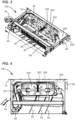
- a telecommunications panel 100 (e.g., an enclosure, an optical distribution frame, etc.) is illustrated according to the principles of the present disclosure.
- the telecommunications panel 100 may be included in a cabinet (not shown).
- the telecommunications panel 100 and/or the cabinet may be used for various purposes in telecommunications systems.
- housing a cable management arrangement including, for example, a cable management basket and a patch panel.
- patch cords i.e., patch cables, connectorized fiber optic cables, etc.
- Fiber optic connectors that terminate ends of the patch cords may connect with the fiber optic adapters of the patch panel.
- the interconnections at the patch panel may be rearranged from time-to-time, as desired, for changing configurations of the telecommunications system.
- the telecommunications panel 100 may further hold various other telecommunications components.
- An exemplary telecommunications system 1 is shown and described in Patent Cooperation Treaty (PCT) publication number WO 2016/042018, filed on September 16, 2015 , the entirety of which is incorporated by reference herein.
- the telecommunications panel 100 may include a chassis 10 to which one or more multi-positionable tray assemblies 20 are removably attached.
- a single tray assembly 20 is attached to the chassis 10.
- the chassis 10 may be configured to hold multiple tray assemblies 20, for example, three or more tray assemblies 20, as shown and described in the WO ⁇ 018 publication.
- the chassis 10 can be configured to support other components of the telecommunications panel 100, as desired.
- the chassis 10 can be configured to support cable management structures 44 and 46.
- cable management structure 44 is configured to guide patch cords extending from the tray assembly 20.
- the cable management structure 46 is configured to allow one or more cables to enter the chassis 10 and tray 20.
- the tray 20 may also be configured to support various cable management structures.
- cable management structures 48 and 50 may be provided to guide patch cords towards cable management structure 44.
- the telecommunications panel 100 further includes a patch panel 104 including a plurality of fiber optic adapters 108 supported by a patch panel frame 106.
- the fiber optic adapters 108 are LC-type adapters. However, other types of adapters may be provided, for example, SC-type adapters.
- the fiber optic adapters 108 are configured to receive fiber optic connectors on each side of the patch panel 104.
- the multi-positionable tray assembly 20 can include a tray 22 (e.g., a sub-rack) and a support arm 24 that are pivotally connected to each other via a pivot joint 26 that allows the tray assembly 20 to be moved between a folded position and an access position.
- the pivot joint 26 is formed by the interface between an upper joint arm of the support arm 24 and an upper joint extension of the tray 22 and by the interface between a lower joint arm of the support arm 24 and a lower joint extension of the tray 22.
- the interfaces can be secured together by a variety of means, for example, a snap-fit type connection via protrusions and corresponding recesses or by a connection utilizing fasteners.
- the pivot joint 26 represents the connection between the tray 22 and the support arm 24 to the chassis 10 and defines a vertical hinge with an axis for the multi-positionable tray assembly 20.
- the pivot joint 26 and support arm 24 are shown as being provided on the left-hand side of the tray 22 (as viewed at Figure 6 , for example) to result in a left-hand swinging tray, the tray 22 may be configured such that the pivot joint 26 and support arm 24 are provided on the right-hand side of the tray 22 to result in a right-hand swinging tray 22.
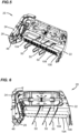
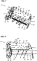
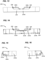
- the tray 22 is configured with multiple attachment feature arrangements 50 which enables the tray 22 to accept various types of telecommunications components, for example the cable management basket 200 shown at Figures 3 to 6 and 9 to 16 .
- the tray 22 includes a rear sidewall 22a, a front sidewall 22b, a second sidewall 22d, an interior wall structure 22e, and a bottom wall 22f.
- Various cable guide structures 22g extending from the bottom wall 22f are also shown as being provided.
- various attachment features are provided such that the cable management basket 200 can be removably secured to the tray 22.
- a pair of spaced attachment features 52 is provided at the rear sidewall 22a of the tray 22.
- An attachment feature 55 is also provided at the rear sidewall 22a and between the attachment features 52.
- Another pair of attachment features 56 is provided on the bottom wall 422h.
- Attachment features can also be provided at a front sidewall 22h.
- a pair of attachment features 57 can be provided, each of which is similarly configured to the attachment feature 55.
- Yet another attachment feature 59 can be provided and is shown as being located between the attachment features 457. Attachment features 52, 55, 56, 57, and 59 are further shown and described in the WO ⁇ 018 publication.
- the hubs 206 can be provided with recessed or scalloped regions 206b such that a gap 206c is provided between the tines 208a, 208b and the hubs 206.
- the gap 206c allows for the cables to be installed and removed during wrapping and unwrapping about the hubs 206.
- the hubs 206 and tines 208 are shown as being integrally formed with the cable management basket 200 bottom wall 202 and outer perimeter wall 204.
- a transition area with cable retention members 220 can also be provided adjacent the retention structure 212 to facilitate cable repair.
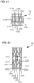
- An example repair station block 220 is shown at Figure 22 and installed within the tray at Figure 23 .
- the retention structures 210, 212, 214 and the cable retention members 220 are integrally formed with the cable management basket 200 bottom wall 202 and/or perimeter wall 204.
- the cable management basket 200 is further shown as being provided with attachment features 222 for enabling the basket 200 to be secured to the tray 20.
- the basket 200 is provided with attachment features 222a and 222b for connecting to the attachment features 52 and 55 and is provided with attachment features 222c, configured as apertures, for connecting to attachment features 56 on the tray 20.
- the basket 200 can also be configure to connect to the attachment features 57 and 59.
- the cable management basket 200 is symmetrical about a transverse centerline axis X1 (see Figure 11 ).
- the tray 20 can be configured for either a right-hand swing or left-hand swing without requiring a differently configured cable management basket 200. Accordingly, the disclosed example is advantageous in that the number of unique components required for various configurations is reduced.
- a cable retention block 218 is shown in isolation.
- the cable retention block 218 is unitarily formed with a bottom wall 218a from which a plurality of sidewall extensions 218b extend to define a plurality of interior channels 218c.
- the retention block 218 is also shown as including a pair of protrusions 218d which engage with the retention structures 212 such that the retention blocks 218 can be retained in with snap-fit type connection.
- each of the sidewall extensions 218b is provided with a plurality of vertically extending barbs or ribs 218e for aiding in retaining cables within the interior channels 218c.
- a tube holder 216 is shown in isolation.
- the tube holder 216 is configured as two separate members 216a, 216b with each including a plurality of sidewalls 216c extending from a base wall 216d to define a pair of channels 216e.
- the sidewalls 216c extend horizontally across the channels 216e such that a narrowed passageway is defined to better retain the cables within the channels 216e.
- Other configurations are possible.
- the tube holder 216 could be provided as a single component with more or fewer channels 216e.
- a repair station block 220 is shown in isolation. As shown, the repair station block 220 includes a base wall 220a from which a plurality of sidewalls 220b extend to define a plurality of channels 220c for retaining an individual cable during a repair operation.
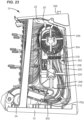
- a pre-cabled telecommunications panel 100 utilizing the above-described components is presented. It is noted that the example shown in Figure 23 is configured with a right-hand swinging tray 20 in contrast to the example shown at Figures 1 to 8 .
- a trunk cable 300 including a plurality of jacketed fiber optic cables 302 enters the telecommunications panel 100 at a rear side of the panel, for example via cable management structure 46.
- the trunk cable 300 extends along the rear side of the chassis 10 adjacent the tray rear wall 22a to a distribution component 304 that is mounted to the chassis 10. With the distribution component 304, an outer jacket of the trunk cable 300 is removed to expose the individual fiber optic cables 302 which exit the distribution component 304 at an opposite end.
- the distribution component 304 can include a lacing structure to organize the fiber optic cables 302.
- the distribution component 304 secures the trunk cable 300 and each of the fiber optic cables 302 and provides a strain-relief function against tensile forces exerted on the trunk cable 300 from being exerted onto the fiber optic cables 302. In one example, this function is accomplished by securing a strength member of the trunk cable 300 to an anchor point within the distribution component 304.
- the fiber optic cables 302 continue to extend along a cable routing pathway defined along the back side 22a of the tray 22 and the support arm 24. As the cables exit the support arm, the cables are routed about the cable routing structure 22g (i.e. bend radius limiter) and into the cable management basket 200 via opening 204c. After entering into the basket 200, the cables 302 are bundled and secured by the tube holders 216. At a location between the tube holders 216 and the cable retention blocks 218, the outer jackets of the fiber optic cables 302 are removed to expose a plurality of optical fibers 306. In the example shown, the optical fibers 306 have a nominal diameter of about 250 ⁇ .
- the optical fibers 306 are then provided with color-coded overtubing 308 having a nominal diameter of about 900 ⁇ .
- the optical fibers 306 and overtubing 308 are then organized and secured by the cable retention blocks 218.
- the optical fibers 306 and overtubing 308 then exit the opening 204d are are routed individually to the adapters 108 with the excess cable lengths being wrapped around hub 206. Where a left-hand swinging tray 20 is provided, the optical fibers 306 and overtubing 308 would be wrapped around the opposite hub 206 with the fiber optic cables 302 entering the opening 204d of the basket 200.
- a telecommunications panel 10 can be entirely cabled within a factory setting with a predetermined length of trunk cable 300 and then shipped for later installation. This approach allows for cabling within the panel 10 to be installed in a much more controlled setting, therefore increasing the quality of the installation and greatly reducing field installation time, particularly since the disclosed panel 10 eliminates the need for field splicing.
- the cable management basket 200 is unitarily formed from a polymeric material.
- the basket 200 could be formed from a metal material and/or with separately formed components that are assembled together to form the basket 200.
Landscapes
- Physics & Mathematics (AREA)
- General Physics & Mathematics (AREA)
- Optics & Photonics (AREA)
- Engineering & Computer Science (AREA)
- Manufacturing & Machinery (AREA)
- Light Guides In General And Applications Therefor (AREA)
- Mechanical Coupling Of Light Guides (AREA)
Applications Claiming Priority (3)
| Application Number | Priority Date | Filing Date | Title |
|---|---|---|---|
| US201862775170P | 2018-12-04 | 2018-12-04 | |
| PCT/EP2019/083550 WO2020115074A1 (en) | 2018-12-04 | 2019-12-03 | Telecommunications panel |
| EP19816623.3A EP3891540B1 (de) | 2018-12-04 | 2019-12-03 | Telekommunikationstafel |
Related Parent Applications (1)
| Application Number | Title | Priority Date | Filing Date |
|---|---|---|---|
| EP19816623.3A Division EP3891540B1 (de) | 2018-12-04 | 2019-12-03 | Telekommunikationstafel |
Publications (2)
| Publication Number | Publication Date |
|---|---|
| EP4513244A2 true EP4513244A2 (de) | 2025-02-26 |
| EP4513244A3 EP4513244A3 (de) | 2025-05-28 |
Family
ID=68808351
Family Applications (2)
| Application Number | Title | Priority Date | Filing Date |
|---|---|---|---|
| EP24209536.2A Pending EP4513244A3 (de) | 2018-12-04 | 2019-12-03 | Telekommunikationstafel |
| EP19816623.3A Active EP3891540B1 (de) | 2018-12-04 | 2019-12-03 | Telekommunikationstafel |
Family Applications After (1)
| Application Number | Title | Priority Date | Filing Date |
|---|---|---|---|
| EP19816623.3A Active EP3891540B1 (de) | 2018-12-04 | 2019-12-03 | Telekommunikationstafel |
Country Status (3)
| Country | Link |
|---|---|
| EP (2) | EP4513244A3 (de) |
| PL (1) | PL3891540T3 (de) |
| WO (1) | WO2020115074A1 (de) |
Families Citing this family (2)
| Publication number | Priority date | Publication date | Assignee | Title |
|---|---|---|---|---|
| PL3891540T3 (pl) | 2018-12-04 | 2025-03-03 | CommScope Connectivity Belgium BVBA | Panel telekomunikacyjny |
| EP4581417A1 (de) * | 2022-09-02 | 2025-07-09 | CommScope Technologies LLC | Telekommunikationstafel und korb |
Citations (2)
| Publication number | Priority date | Publication date | Assignee | Title |
|---|---|---|---|---|
| WO2016042018A2 (en) | 2014-09-16 | 2016-03-24 | Tyco Electronics Raychem Bvba | Telecommunications tray assembly |
| EP3891540A1 (de) | 2018-12-04 | 2021-10-13 | CommScope Connectivity Belgium BVBA | Telekommunikationstafel |
Family Cites Families (5)
| Publication number | Priority date | Publication date | Assignee | Title |
|---|---|---|---|---|
| US5323480A (en) * | 1992-11-25 | 1994-06-21 | Raychem Corporation | Fiber optic splice closure |
| GB9318632D0 (en) * | 1993-09-08 | 1993-10-27 | Raychem Sa Nv | Optical fibre organizer |
| US7970249B2 (en) * | 2008-02-15 | 2011-06-28 | Adc Telecommunications, Inc. | Fiber optic splice enclosure |
| WO2014122104A2 (en) * | 2013-02-05 | 2014-08-14 | Tyco Electronics Raychem Bvba | Management tray with fiber bundle locking arrangement |
| EP3032304B1 (de) * | 2014-12-05 | 2018-11-28 | CommScope Connectivity Belgium BVBA | Vorverkabelte telekommunikationsanordnung |
-
2019
- 2019-12-03 PL PL19816623.3T patent/PL3891540T3/pl unknown
- 2019-12-03 WO PCT/EP2019/083550 patent/WO2020115074A1/en not_active Ceased
- 2019-12-03 EP EP24209536.2A patent/EP4513244A3/de active Pending
- 2019-12-03 EP EP19816623.3A patent/EP3891540B1/de active Active
Patent Citations (2)
| Publication number | Priority date | Publication date | Assignee | Title |
|---|---|---|---|---|
| WO2016042018A2 (en) | 2014-09-16 | 2016-03-24 | Tyco Electronics Raychem Bvba | Telecommunications tray assembly |
| EP3891540A1 (de) | 2018-12-04 | 2021-10-13 | CommScope Connectivity Belgium BVBA | Telekommunikationstafel |
Also Published As
| Publication number | Publication date |
|---|---|
| EP3891540B1 (de) | 2024-10-30 |
| WO2020115074A1 (en) | 2020-06-11 |
| EP4513244A3 (de) | 2025-05-28 |
| PL3891540T3 (pl) | 2025-03-03 |
| EP3891540A1 (de) | 2021-10-13 |
Similar Documents
| Publication | Publication Date | Title |
|---|---|---|
| EP4006606B1 (de) | Multipositionierbare telekommunikationsplatte | |
| EP1325371B1 (de) | Faserverteiler-halterungssystem mit hoher dichte | |
| US10627591B2 (en) | Rotatable patch cable holder | |
| EP3998503B1 (de) | Telekommunikationsplatte mit einem kabelführungsweg, der durch ein zapfenband verläuft | |
| US20190072736A1 (en) | High density distribution frame with an integrated splicing compartment | |
| US6061492A (en) | Apparatus and method for interconnecting fiber cables | |
| US6621975B2 (en) | Distribution terminal for network access point | |
| US6633717B1 (en) | High density fiber optic cable distribution frame system | |
| EP2237091A1 (de) | Lösbar montierbares LWL-Leitungsendgerät | |
| WO2009106874A1 (en) | Optical fibre organiser | |
| EP0623225A1 (de) | Faseroptisches verbindungssystem | |
| US20200081217A1 (en) | Tray assembly for a fiber optic system | |
| EP3891540B1 (de) | Telekommunikationstafel | |
| WO2022035966A1 (en) | Optical fiber organizer with improved fiber routing customizability for a telecommunications closure | |
| US20160216471A1 (en) | Fiber optic assemblies with a fiber optic cable movable between cable openings | |
| EP4581417A1 (de) | Telekommunikationstafel und korb | |
| EP3919955B1 (de) | Kabelmanagerteil für telekommunikationsplattenanordnung |
Legal Events
| Date | Code | Title | Description |
|---|---|---|---|
| PUAI | Public reference made under article 153(3) epc to a published international application that has entered the european phase |
Free format text: ORIGINAL CODE: 0009012 |
|
| STAA | Information on the status of an ep patent application or granted ep patent |
Free format text: STATUS: THE APPLICATION HAS BEEN PUBLISHED |
|
| AC | Divisional application: reference to earlier application |
Ref document number: 3891540 Country of ref document: EP Kind code of ref document: P |
|
| AK | Designated contracting states |
Kind code of ref document: A2 Designated state(s): AL AT BE BG CH CY CZ DE DK EE ES FI FR GB GR HR HU IE IS IT LI LT LU LV MC MK MT NL NO PL PT RO RS SE SI SK SM TR |
|
| PUAL | Search report despatched |
Free format text: ORIGINAL CODE: 0009013 |
|
| AK | Designated contracting states |
Kind code of ref document: A3 Designated state(s): AL AT BE BG CH CY CZ DE DK EE ES FI FR GB GR HR HU IE IS IT LI LT LU LV MC MK MT NL NO PL PT RO RS SE SI SK SM TR |
|
| RIC1 | Information provided on ipc code assigned before grant |
Ipc: G02B 6/44 20060101AFI20250422BHEP |
|
| STAA | Information on the status of an ep patent application or granted ep patent |
Free format text: STATUS: REQUEST FOR EXAMINATION WAS MADE |
|
| 17P | Request for examination filed |
Effective date: 20251127 |
|
| GRAP | Despatch of communication of intention to grant a patent |
Free format text: ORIGINAL CODE: EPIDOSNIGR1 |
|
| STAA | Information on the status of an ep patent application or granted ep patent |
Free format text: STATUS: GRANT OF PATENT IS INTENDED |