EP4513239A2 - Verfahren und mittel zur bewertung und überwachung von formationskriech- und schiefersperren unter verwendung von ionisierender strahlung - Google Patents
Verfahren und mittel zur bewertung und überwachung von formationskriech- und schiefersperren unter verwendung von ionisierender strahlung Download PDFInfo
- Publication number
- EP4513239A2 EP4513239A2 EP24216536.3A EP24216536A EP4513239A2 EP 4513239 A2 EP4513239 A2 EP 4513239A2 EP 24216536 A EP24216536 A EP 24216536A EP 4513239 A2 EP4513239 A2 EP 4513239A2
- Authority
- EP
- European Patent Office
- Prior art keywords
- tool
- shale
- density
- detectors
- production
- Prior art date
- Legal status (The legal status is an assumption and is not a legal conclusion. Google has not performed a legal analysis and makes no representation as to the accuracy of the status listed.)
- Pending
Links
Images


Classifications
-
- G—PHYSICS
- G01—MEASURING; TESTING
- G01V—GEOPHYSICS; GRAVITATIONAL MEASUREMENTS; DETECTING MASSES OR OBJECTS; TAGS
- G01V5/00—Prospecting or detecting by the use of ionising radiation, e.g. of natural or induced radioactivity
- G01V5/04—Prospecting or detecting by the use of ionising radiation, e.g. of natural or induced radioactivity specially adapted for well-logging
- G01V5/08—Prospecting or detecting by the use of ionising radiation, e.g. of natural or induced radioactivity specially adapted for well-logging using primary nuclear radiation sources or X-rays
- G01V5/12—Prospecting or detecting by the use of ionising radiation, e.g. of natural or induced radioactivity specially adapted for well-logging using primary nuclear radiation sources or X-rays using gamma or X-ray sources
-
- G—PHYSICS
- G01—MEASURING; TESTING
- G01V—GEOPHYSICS; GRAVITATIONAL MEASUREMENTS; DETECTING MASSES OR OBJECTS; TAGS
- G01V5/00—Prospecting or detecting by the use of ionising radiation, e.g. of natural or induced radioactivity
- G01V5/04—Prospecting or detecting by the use of ionising radiation, e.g. of natural or induced radioactivity specially adapted for well-logging
- G01V5/045—Transmitting data to recording or processing apparatus; Recording data
Definitions
- the present invention relates generally to management of hydrocarbon producing wells, and in a particular though non-limiting embodiment to methods and means for monitoring and determining annular seal integrity, zonal isolation, and well integrity within single or multi-string wellbore environments that use formation creep or shale as a means to provide a zonal barrier.
- ultra-sonic tools are run within the well to determine whether the annular materials are bonded to the outside of the casing, thereby indicating the presence of cement in the annulus between the casing and formation, or between the casing and an outer casing.
- a leak-off (pressure) test is required to ensure that zonal isolation has been achieved as Ultrasonic tools are highly dependent upon quality of the casing, the bond between the casing and the material in the annulus, and the mechanical properties of the material in the annulus to be able to work correctly.
- ultrasonic tools treat the material in the annulus as a single isotropic and homogenous volume, any actual deviation away from this ideal leads to inaccuracies in the measurement.
- P&A Plugging and abandonment of old well tracks require suitable barriers to be put in place.
- Barrier requirements for example NORSOK D-010, require a double barrier approach, which is typically satisfied by annular cement and the wellhead itself.
- the wellhead is often removed, such that an additional barrier is required.
- the primary barrier e.g., cement
- the primary barrier e.g., cement
- an additional 50m interval of secondary barrier needs to be demonstrated as well.
- Shale could be used as a formation 'barrier' as is creeps and swells, thereby sealing around the casing.
- current technologies cannot accurately assess the quality of the seal created by the shale, as shale that has physically pressed against the outer-diameter of the well casing can be detected, but not whether fluid migration paths exist within the shale itself.
- a permanent well barrier will ideally have the following properties:
- Swelling shale which has been shown to invade the annular materials surrounding a well casing, can satisfy the above requirements. However, the need to prove the quality and distribution of the shale is still paramount.
- US 7,675,029 B2 teaches an apparatus that permits the measurement of x-ray backscattered photons from any horizontal surface inside of a borehole using two-dimensional imaging techniques.
- US 8,481,919 B2 teaches a method of producing Compton-spectrum radiation in a borehole without the use of radioactive isotopes, and further describes rotating collimators disposed around a fixed source installed internally to the apparatus, but does not have solid-state detectors with collimators.
- the ⁇ 919 to Teague also teaches of the use of conical and radially symmetrical anode arrangements to permit the production of panoramic x-ray radiation.
- the reference fails to teach of a means or method to achieve such through the steel wall of a single or multiple well casings, thereby discriminating against signals signal originating from behind the casings from annular materials such as cement.
- the reference also fails to disclose a non-padded (i.e ., concentric) tooling technique within a single or multi-string cased hole environment.
- CA 1,022,902 A discloses a liquid-impermeable geo-logic barrier made from shale.
- the preferred shale is Brainard Shale, the upper shale formation in the Maquoketa Group, which is excavated to expose solid, unweathered shale in its original sedimentary state.
- the Brainard shale is removed by a suitable mining operation and then crushed into an aggregate that can be readily compacted.
- Water is added and the shale aggregate is thoroughly mixed to uniformly disperse the water. It is immediately spread in a layer of uniform thickness along a wall to be sealed, and then worked and mixed in place and compacted solid by multiple passes of a sheepsfoot roller. This is repeated in multiple lifts until the barrier reaches a desired total compacted thickness and width.
- US 20180180765 A1 teaches of methods and means to create three-dimensional data-sets of variations in cement-filled annuli surrounding the multiple strings of a borehole.
- US 2018/0,188,411 A1 teaches methods and means for creating three-dimensional data-sets of variations in cement-filled annuli surrounding the multiple strings of a borehole using light-house type source collimation techniques and, in addition to source-angle variations, to significantly increasing the special resolution of the tool.
- US 2017/218749 A1 relates to downhole imaging and, more particularly, to downhole photon tomographic imagine.
- US 2017/218749 A1 refers mainly to photons, but it is mentioned that X-rays can be used.
- US 7,705,294 B2 teaches an apparatus that measures backscattered x-rays from the inner layers of a borehole in selected radial directions, with the missing segment data being populated through movement of the apparatus through the borehole.
- the apparatus permits generation of data for a two-dimensional reconstruction of the well or borehole, though ideally does not expressly teach the necessary geometry for the illuminating x-ray beam to permit discrimination of the depth from which the backscattered photons originated, only their direction.
- US 3,564,251 A discloses the use of a azimuthally scanning collimated x-ray beam used to produce an attenuated signal at a detector for the purposes of producing a spiral-formed log of the inside of a casing or borehole surface immediately surrounding the tool, which is effectively embodied as an x-ray caliper.
- US 7,634,059 B2 discloses an apparatus that may be used to produce individual two-dimensional x-ray images of the inner surface inside of a borehole using a single pin-hole camera without the technical possibility to ascertain the azimuth of the image being taken, such that a tessellation/stitching of multiple images is not disclosed or even possible.
- US 2013/0009049 A1 discloses an apparatus that allows measurement of backscattered x-rays from the inner layers of a borehole.
- US 8,138,471 B2 discloses a scanning-beam apparatus based on an x-ray source, a rotatable x-ray beam collimator, and solid-state radiation detectors enabling the imaging of only the inner surfaces of borehole casings and pipelines.
- US 5,326,970 A discloses a tool for measuring backscattered x-rays azimuthally in a single direction to measure formation density, with the x-ray source being based on a linear accelerator.
- US 5,081,611 A discloses a method of back projection to determine acoustic physical parameters of the earth formation longitudinally along the borehole using a single ultrasonic transducer and a number of receivers, which are distributed along the primary axis of the tool.
- US 6,725,161 B1 discloses a method of placing a transmitter in a borehole and a receiver on the surface of the earth, or a receiver in a borehole and a transmitter on the surface of the earth, in order to determine structural information regarding the geological materials between the transmitter and receiver.
- US 6,876,721 B2 discloses a method of correlating information taken from a core-sample with information from a borehole density log.
- the core-sample information is derived from a CT scan of the core-sample, whereby the x-ray source and detectors are located on the outside of the sample, and thereby configured as an outside-looking-in arrangement.
- Various kinds of information from the CT scan such as its bulk density is compared to and correlated with the log information.
- US 4,464,569 A discloses a method of determining the elemental composition of earth formations surrounding a well borehole by processing the detected neutron capture gamma radiation emanating from the earth formation after neutron irradiation of the earth formation by a neutron spectroscopy logging tool.
- US 4,433,240 A discloses a borehole logging tool that detects natural radiation from the rock of the formation and logs said information so that it may be represented in an intensity versus depth plot format.
- US 3,976,879 A discloses a borehole logging tool that detects and records the backscattered radiation from the formation surrounding the borehole by means of a pulsed electromagnetic energy or photon source so that characteristic information may be represented in an intensity versus depth plot format.
- US 8,664,587 B2 discloses methods and means for creating azimuthal neutron porosity images in a logging while drilling environment.
- this reference discusses an arrangement of azimuthally static detectors that be implemented in a modern BHA that does not necessarily rotate with the bit by subdividing the neutron detectors into a plurality of azimuthally arranged detectors, each of which are shielded within a moderator in order to infer directionality to incident neutrons and gamma rays.
- US 9,012,836 B2 discloses a method and means for creating azimuthal neutron porosity images in a wireline environment.
- the reference discusses an arrangement of azimuthally static detectors that could be implemented in a wireline tool in order to assist an operator in interpreting logs post-fracking by subdividing the neutron detectors into a plurality of azimuthally arranged detectors, each of which are shielded within a moderator so as to infer directionality to incident neutrons and gamma rays.
- US 4,883,956 A discloses methods and means for investigation of subsurface earth formations, using an apparatus adapted for movement through a borehole.
- the apparatus may include a natural or artificial radiation source for irradiating the formations with penetrating radiation such as gamma rays, x-rays or neutrons.
- US 6,078,867 A discloses a method for generating a three-dimensional graphical representation of a borehole, comprising the steps of: receiving caliper data relating to the borehole, generating a three-dimensional wire mesh model of the borehole from the caliper data, and color mapping the three-dimensional wire mesh model from the caliper data based on either borehole form, rugosity and/or lithology.
- WO 2018/156857 A1 discloses methods and means for detecting anomalies in annular materials, and in particular embodiments methods and means for detecting anomalies in the annular materials of single and dual casing string environments.
- An x-ray-based reservoir evaluation tool for the measurement of a shale density anticipated at shale-creep barrier within a cased borehole, the tool including at least an internal length comprising a sonde section, wherein the sonde section further includes at least an x-ray source; a plurality of radiation measuring detectors; sonde-dependent electronics; and a plurality of tool logic electronics and PSUs.
- a method of using an x-ray-based shale-seal evaluation tool for measuring a shale density anticipated at shale-creep barrier within a cased borehole including at least: using x-rays to illuminate a formation surrounding the cased borehole; using detectors to directly measure a density of the formation; using detectors to directly measure the effects on the measurement from tool stand-off or production liner attenuation; and compensating for a production liner and liner-annular region when computing the saturated formation density within a production interval.
- the methods and means described herein quantitively measure the density and distribution of formation materials surrounding a wellbore, especially those in contact with the casing strings, in a package that does not require direct physical contact with the well casings (i.e., non-padded).
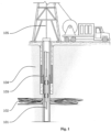
- an x-ray-based reservoir evaluation tool 101 is deployed by wireline conveyance 105 into a cased borehole 103, wherein the tool is deployed into the borehole to determine whether a sufficient seal has been provided by formation 104 creep, such as a shale bed 102.
- the tool is enclosed by a pressure housing that ensures well fluids are maintained outside of the housing.
- Fig. 2 illustrates how a conical x-ray beam 201 interacts with the media surrounding the borehole 202, the prime candidate for investigation being shale 206, the counts are detected an axially offset group of detectors 203, 204, 205.
- Fluid and casing detector 203 data are mostly contributable to single-event scatter mechanisms, whereas shale-distribution detector 204, 205 group data are mostly comprised of multiple scatter event mechanisms.
- cylindrical collimators are used to give directionality to the output of an x-ray source that is located within the pressure housing of a borehole logging tool.
- an azimuthal plurality of x-ray beams are arranged to create a pseudo-cone of x-ray.
- the separate fingers of the pseudo-cone are employed to reduce the amount of cross-talk in signals between the detectors. Consequently, regions of lower density within the annular materials surrounding the borehole are detected at different rates by different azimuthally located detectors, allowing the most likely azimuthal location of the anomaly to be determined. Consequently, lower density regions within the annular materials surrounding the borehole will be detected by different azimuthally located detectors are different rates, such that the most probably azimuthal location of the anomaly can be determined.
- Fig. 3 illustrates how an x-ray beam 301 (shown as a cone) interacts with the shale 302 surrounding the borehole, the counts that are detected at each axially offset group of detectors 303, 304, 305, 306, 307, 308 is a convolution of the various attenuation factor summations of the detected photons as they travelled through and back through each layer 309, 310, 311, 312 of the borehole surroundings.
- An additional function is the mean free path lengths of the various materials as a function of x-ray photon energy.
- the tool is used to determine the position and density of a shale bed through production liners or production casing.
- the tool further comprises additional axially-offset radiation detectors for compensating for the production liner and liner-annular region effects when computing the formation density within the shale bed.
- the data from each detector is deconvoluted through the use of the data collected by the lowest axial offset detector group in order to compensate for fluid-thickness and casing variations alone.
- the signal from each detector is compensated such that the result is a measure of the density of the material within the depth of investigation (region of interest) combined with a function of the attenuations and scattering cross-sections of the materials in lower depths of investigations (or lower axial offsets).
- the lowest axially offset detector group's single scatter bias renders the group ideal for measuring offset between the tool housing and the casing, through the well-fluids.
- the tool will remain mostly centralized.
- any slight variation in well casing diameter (ovality) or inefficiencies in the tool's centralizer mechanisms will result in a longer path length for the x-rays through the wellbore fluid.
- the first order detectors are the primary compensating mechanism for changes in path-length and attenuation for the higher order detectors.
- comparison of each of the azimuthally distributed first order detectors can be employed such that the physical location of the tool within the casing (as a function of offset from the centerline) can be determined.
- comparison of axially offset azimuthal groupings of detectors can also be used to determine the radial position of prospective density anomalies within the shale or formation.
- an anomaly is located within the outer annulus between an outer casing and the formation, then only higher order detector groups will detect a change in incoming photon intensity/counts, whereas lower order detector groups' depth of investigation would be too low to detect said anomaly.
- An anomaly detected by a lower order detector group will be detected by both the lower order anomaly detectors and the higher order detectors as the x-ray beam passes through all of those regions of interest.
- An anomaly located at a lower (inner) depth of investigation will have convoluting impact on the higher order detectors. The difference between the impact on higher and lower order detectors serves as the basis for determining the radial position of a density anomaly located within the annular materials surrounding a borehole.
- the data collected from each azimuthal plane is processed to create a two dimensional density map of the shale extending out from the outer surface of the first casing to a significant distance into the formation surrounding the borehole, thereby capturing all of the density data for the materials as a function of axial position and radial position, over a significant axial interval, such as 50 meters, by moving the tool through the well.
- the data collected from each ⁇ azimuth' is compared with neighboring azimuths to ascertain the azimuthal position of an anomaly so that the two dimensional maps can be amalgamated into a three dimensional map of the density data for the materials as a function of axial position, azimuthal and radial position
- the data collected is presented as either traditional 2D logs (as a function of depth), as a three-dimensional density model, or as slices or sections of such.
- the data can also be further processed through machine learning so that a neural network is trained to look for signal abnormalities, or by setting simple discriminators on the (calibrated) gradients and differences between axially offset detector group data collections.
- the density log data is combinable with other measurements, such as neutron porosity, to improve the quality of the interpretation of the data to better determine the depth at which the shale bed exists.
- existing open-hole logs are used to establish a baseline profile, as a function of depth, for the formation density so that sensitivity to the formation seal could be improved.
- the tool is integrated into a Logging-while-drilling tool.
- the tool is configured for thru-wiring for combination with other tools.
- the tool would be powered by a mud turbine.
- the tool is powered by a battery.
- machine learning is used such that algorithms are taught indicators of a good shale seal when comparing logs and log types so that the process of determining the presence and/or quality of the shale seal can be automated.
- the tool is used to determine the position and density of a shale bed through production liners or production casing.
- the tool is configured to determine the position and density of a shale bed through production liners or production casing, wherein the tool further comprises additional axially-offset radiation detectors configured to compensate production liner and liner-annular region effects when computing a formation density within the shale bed.
Landscapes
- Physics & Mathematics (AREA)
- High Energy & Nuclear Physics (AREA)
- Life Sciences & Earth Sciences (AREA)
- General Life Sciences & Earth Sciences (AREA)
- General Physics & Mathematics (AREA)
- Geophysics (AREA)
- Analysing Materials By The Use Of Radiation (AREA)
- Geophysics And Detection Of Objects (AREA)
Applications Claiming Priority (3)
| Application Number | Priority Date | Filing Date | Title |
|---|---|---|---|
| US201862666440P | 2018-05-03 | 2018-05-03 | |
| PCT/US2019/030676 WO2019213580A1 (en) | 2018-05-03 | 2019-05-03 | Methods and means for evaluating and monitoring formation creep and shale barriers using ionizing radiation |
| EP19724680.4A EP3788415A1 (de) | 2018-05-03 | 2019-05-03 | Verfahren und mittel zur bewertung und überwachung der bildung von kriech- und schieferbarrieren mit ionisierender strahlung |
Related Parent Applications (1)
| Application Number | Title | Priority Date | Filing Date |
|---|---|---|---|
| EP19724680.4A Division EP3788415A1 (de) | 2018-05-03 | 2019-05-03 | Verfahren und mittel zur bewertung und überwachung der bildung von kriech- und schieferbarrieren mit ionisierender strahlung |
Publications (2)
| Publication Number | Publication Date |
|---|---|
| EP4513239A2 true EP4513239A2 (de) | 2025-02-26 |
| EP4513239A3 EP4513239A3 (de) | 2025-04-30 |
Family
ID=67616814
Family Applications (2)
| Application Number | Title | Priority Date | Filing Date |
|---|---|---|---|
| EP24216536.3A Pending EP4513239A3 (de) | 2018-05-03 | 2019-05-03 | Verfahren und mittel zur bewertung und überwachung von formationskriech- und schiefersperren unter verwendung von ionisierender strahlung |
| EP19724680.4A Ceased EP3788415A1 (de) | 2018-05-03 | 2019-05-03 | Verfahren und mittel zur bewertung und überwachung der bildung von kriech- und schieferbarrieren mit ionisierender strahlung |
Family Applications After (1)
| Application Number | Title | Priority Date | Filing Date |
|---|---|---|---|
| EP19724680.4A Ceased EP3788415A1 (de) | 2018-05-03 | 2019-05-03 | Verfahren und mittel zur bewertung und überwachung der bildung von kriech- und schieferbarrieren mit ionisierender strahlung |
Country Status (5)
| Country | Link |
|---|---|
| US (1) | US11035978B2 (de) |
| EP (2) | EP4513239A3 (de) |
| AU (1) | AU2019262636B2 (de) |
| CA (1) | CA3099022C (de) |
| WO (1) | WO2019213580A1 (de) |
Families Citing this family (1)
| Publication number | Priority date | Publication date | Assignee | Title |
|---|---|---|---|---|
| US20190187325A1 (en) * | 2018-02-14 | 2019-06-20 | Philip Teague | Methods and means for neutron imaging within a borehole |
Citations (21)
| Publication number | Priority date | Publication date | Assignee | Title |
|---|---|---|---|---|
| US3564251A (en) | 1968-03-04 | 1971-02-16 | Dresser Ind | Casing inspection method and apparatus |
| US3976879A (en) | 1975-05-22 | 1976-08-24 | Schlumberger Technology Corporation | Well logging method and apparatus using a continuous energy spectrum photon source |
| CA1022902A (en) | 1973-07-20 | 1977-12-20 | Svenska Rotor Maskiner Aktiebolag | Screw compressor |
| US4433240A (en) | 1980-06-25 | 1984-02-21 | Schlumberger Technology Corporation | Method and apparatus for measuring gamma rays in a borehole |
| US4464569A (en) | 1981-06-19 | 1984-08-07 | Schlumberger Technology Corporation | Method and apparatus for spectroscopic analysis of a geological formation |
| US4883956A (en) | 1985-12-23 | 1989-11-28 | Schlumberger Technology Corporation | Methods and apparatus for gamma-ray spectroscopy and like measurements |
| US5081611A (en) | 1991-03-06 | 1992-01-14 | Schlumberger Technology Corporation | Methods for determining formation and borehole parameters via two-dimensional tomographic reconstruction of formation slowness |
| US5326970A (en) | 1991-11-12 | 1994-07-05 | Bayless John R | Method and apparatus for logging media of a borehole |
| US6078867A (en) | 1998-04-08 | 2000-06-20 | Schlumberger Technology Corporation | Method and apparatus for generation of 3D graphical borehole analysis |
| US6725161B1 (en) | 2001-04-26 | 2004-04-20 | Applied Minds, Inc. | Method for locating and identifying underground structures with horizontal borehole to surface tomography |
| US6876721B2 (en) | 2003-01-22 | 2005-04-05 | Saudi Arabian Oil Company | Method for depth-matching using computerized tomography |
| US7634059B2 (en) | 2007-12-05 | 2009-12-15 | Schlumberger Technology Corporation | Downhole imaging tool utilizing x-ray generator |
| US7675029B2 (en) | 2003-08-29 | 2010-03-09 | Visuray As | Apparatus and a method for visualizing target objects in a fluid-carrying pipe |
| US8138471B1 (en) | 2010-12-09 | 2012-03-20 | Gas Technology Institute | X-ray backscatter device for wellbore casing and pipeline inspection |
| US20130009049A1 (en) | 2009-07-01 | 2013-01-10 | Ge Oil & Gas Logging Services, Inc. | Method For Inspecting A Subterranean Tubular |
| US8481919B2 (en) | 2009-10-23 | 2013-07-09 | Visuray Technology Ltd. | Apparatus and method for controllable downhole production of ionizing radiation without the use of radioactive chemical isotopes |
| US8664587B2 (en) | 2010-11-19 | 2014-03-04 | Schlumberger Technology Corporation | Non-rotating logging-while-drilling neutron imaging tool |
| US9012836B2 (en) | 2011-10-27 | 2015-04-21 | Weatherford Technology Holdings, Llc | Neutron logging tool with multiple detectors |
| US20170218749A1 (en) | 2014-10-02 | 2017-08-03 | Halliburton Energy Services, Inc. | Downhole tomographic imaging |
| US20180180765A1 (en) | 2017-02-27 | 2018-06-28 | Philip Teague | Detecting Anomalies in Annular Materials of Single and Dual Casing String Environments |
| US20180188411A1 (en) | 2017-02-24 | 2018-07-05 | Philip Teague | Resolution of Detection of an Azimuthal Distribution of Materials in Multi-Casing Wellbore Environments |
Family Cites Families (5)
| Publication number | Priority date | Publication date | Assignee | Title |
|---|---|---|---|---|
| US7564948B2 (en) * | 2006-12-15 | 2009-07-21 | Schlumberger Technology Corporation | High voltage x-ray generator and related oil well formation analysis apparatus and method |
| US8899107B2 (en) * | 2009-03-11 | 2014-12-02 | Schlumberger Technology Corporation | Downhole determination of asphaltene content |
| US9217323B2 (en) | 2012-09-24 | 2015-12-22 | Schlumberger Technology Corporation | Mechanical caliper system for a logging while drilling (LWD) borehole caliper |
| US20180113233A1 (en) * | 2015-12-15 | 2018-04-26 | Baker Hughes Incorporated | Determination of concentration of chemical elements in an earth formation from non-coaxial dual detector radiation measurements |
| US10705247B2 (en) * | 2017-11-22 | 2020-07-07 | Visuray Intech Ltd (Bvi) | Methods and means for fracture mapping in a well bore |
-
2019
- 2019-05-03 AU AU2019262636A patent/AU2019262636B2/en active Active
- 2019-05-03 EP EP24216536.3A patent/EP4513239A3/de active Pending
- 2019-05-03 WO PCT/US2019/030676 patent/WO2019213580A1/en not_active Ceased
- 2019-05-03 US US16/403,107 patent/US11035978B2/en active Active
- 2019-05-03 CA CA3099022A patent/CA3099022C/en active Active
- 2019-05-03 EP EP19724680.4A patent/EP3788415A1/de not_active Ceased
Patent Citations (23)
| Publication number | Priority date | Publication date | Assignee | Title |
|---|---|---|---|---|
| US3564251A (en) | 1968-03-04 | 1971-02-16 | Dresser Ind | Casing inspection method and apparatus |
| CA1022902A (en) | 1973-07-20 | 1977-12-20 | Svenska Rotor Maskiner Aktiebolag | Screw compressor |
| US3976879A (en) | 1975-05-22 | 1976-08-24 | Schlumberger Technology Corporation | Well logging method and apparatus using a continuous energy spectrum photon source |
| US4433240A (en) | 1980-06-25 | 1984-02-21 | Schlumberger Technology Corporation | Method and apparatus for measuring gamma rays in a borehole |
| US4464569A (en) | 1981-06-19 | 1984-08-07 | Schlumberger Technology Corporation | Method and apparatus for spectroscopic analysis of a geological formation |
| US4883956A (en) | 1985-12-23 | 1989-11-28 | Schlumberger Technology Corporation | Methods and apparatus for gamma-ray spectroscopy and like measurements |
| US5081611A (en) | 1991-03-06 | 1992-01-14 | Schlumberger Technology Corporation | Methods for determining formation and borehole parameters via two-dimensional tomographic reconstruction of formation slowness |
| US5326970A (en) | 1991-11-12 | 1994-07-05 | Bayless John R | Method and apparatus for logging media of a borehole |
| US6078867A (en) | 1998-04-08 | 2000-06-20 | Schlumberger Technology Corporation | Method and apparatus for generation of 3D graphical borehole analysis |
| US6725161B1 (en) | 2001-04-26 | 2004-04-20 | Applied Minds, Inc. | Method for locating and identifying underground structures with horizontal borehole to surface tomography |
| US6876721B2 (en) | 2003-01-22 | 2005-04-05 | Saudi Arabian Oil Company | Method for depth-matching using computerized tomography |
| US7675029B2 (en) | 2003-08-29 | 2010-03-09 | Visuray As | Apparatus and a method for visualizing target objects in a fluid-carrying pipe |
| US7705294B2 (en) | 2003-08-29 | 2010-04-27 | Visuray As | Method of visualizing target objects in a fluid-carrying pipe |
| US7634059B2 (en) | 2007-12-05 | 2009-12-15 | Schlumberger Technology Corporation | Downhole imaging tool utilizing x-ray generator |
| US20130009049A1 (en) | 2009-07-01 | 2013-01-10 | Ge Oil & Gas Logging Services, Inc. | Method For Inspecting A Subterranean Tubular |
| US8481919B2 (en) | 2009-10-23 | 2013-07-09 | Visuray Technology Ltd. | Apparatus and method for controllable downhole production of ionizing radiation without the use of radioactive chemical isotopes |
| US8664587B2 (en) | 2010-11-19 | 2014-03-04 | Schlumberger Technology Corporation | Non-rotating logging-while-drilling neutron imaging tool |
| US8138471B1 (en) | 2010-12-09 | 2012-03-20 | Gas Technology Institute | X-ray backscatter device for wellbore casing and pipeline inspection |
| US9012836B2 (en) | 2011-10-27 | 2015-04-21 | Weatherford Technology Holdings, Llc | Neutron logging tool with multiple detectors |
| US20170218749A1 (en) | 2014-10-02 | 2017-08-03 | Halliburton Energy Services, Inc. | Downhole tomographic imaging |
| US20180188411A1 (en) | 2017-02-24 | 2018-07-05 | Philip Teague | Resolution of Detection of an Azimuthal Distribution of Materials in Multi-Casing Wellbore Environments |
| US20180180765A1 (en) | 2017-02-27 | 2018-06-28 | Philip Teague | Detecting Anomalies in Annular Materials of Single and Dual Casing String Environments |
| WO2018156857A1 (en) | 2017-02-27 | 2018-08-30 | Philip Teague | Detecting anomalies in annular materials of single and dual casing string environments |
Also Published As
| Publication number | Publication date |
|---|---|
| WO2019213580A1 (en) | 2019-11-07 |
| US11035978B2 (en) | 2021-06-15 |
| US20190257976A1 (en) | 2019-08-22 |
| EP4513239A3 (de) | 2025-04-30 |
| AU2019262636B2 (en) | 2022-10-20 |
| EP3788415A1 (de) | 2021-03-10 |
| CA3099022A1 (en) | 2019-11-07 |
| CA3099022C (en) | 2023-02-28 |
| AU2019262636A1 (en) | 2020-12-17 |
Similar Documents
| Publication | Publication Date | Title |
|---|---|---|
| EP3586173B1 (de) | Erkennung von anomalien in ringförmigen materialien von einzel- und dualrohrstrangumgebungen | |
| EP3586171B1 (de) | Verbesserung der auflösung der detektion einer azimuthalen verteilung von materialien in bohrlochumgebungen mit mehreren gehäusen | |
| US20230194748A1 (en) | Methods and Means for Simultaneous Casing Integrity Evaluation and Cement Inspection in a Multiple-Casing Wellbore Environment | |
| US11542808B2 (en) | Methods and means for determining the existence of cement debonding within a cased borehole using x-ray techniques | |
| US20190271794A1 (en) | Methods and means for measuring multiple casing wall thicknesses using x-ray radiation in a wellbore environment | |
| US11035978B2 (en) | Methods and means for evaluating and monitoring formation creep and shale barriers using ionizing radiation |
Legal Events
| Date | Code | Title | Description |
|---|---|---|---|
| PUAI | Public reference made under article 153(3) epc to a published international application that has entered the european phase |
Free format text: ORIGINAL CODE: 0009012 |
|
| STAA | Information on the status of an ep patent application or granted ep patent |
Free format text: STATUS: THE APPLICATION HAS BEEN PUBLISHED |
|
| AC | Divisional application: reference to earlier application |
Ref document number: 3788415 Country of ref document: EP Kind code of ref document: P |
|
| AK | Designated contracting states |
Kind code of ref document: A2 Designated state(s): AL AT BE BG CH CY CZ DE DK EE ES FI FR GB GR HR HU IE IS IT LI LT LU LV MC MK MT NL NO PL PT RO RS SE SI SK SM TR |
|
| PUAL | Search report despatched |
Free format text: ORIGINAL CODE: 0009013 |
|
| AK | Designated contracting states |
Kind code of ref document: A3 Designated state(s): AL AT BE BG CH CY CZ DE DK EE ES FI FR GB GR HR HU IE IS IT LI LT LU LV MC MK MT NL NO PL PT RO RS SE SI SK SM TR |
|
| RIC1 | Information provided on ipc code assigned before grant |
Ipc: G01V 5/12 20060101AFI20250327BHEP |
|
| STAA | Information on the status of an ep patent application or granted ep patent |
Free format text: STATUS: REQUEST FOR EXAMINATION WAS MADE |
|
| 17P | Request for examination filed |
Effective date: 20251030 |