EP4513179A1 - Impedance measurement apparatus and impedance measurement method - Google Patents
Impedance measurement apparatus and impedance measurement method Download PDFInfo
- Publication number
- EP4513179A1 EP4513179A1 EP23791669.7A EP23791669A EP4513179A1 EP 4513179 A1 EP4513179 A1 EP 4513179A1 EP 23791669 A EP23791669 A EP 23791669A EP 4513179 A1 EP4513179 A1 EP 4513179A1
- Authority
- EP
- European Patent Office
- Prior art keywords
- electrode
- voltage
- detection circuit
- electrodes
- impedance
- Prior art date
- Legal status (The legal status is an assumption and is not a legal conclusion. Google has not performed a legal analysis and makes no representation as to the accuracy of the status listed.)
- Pending
Links
Images


Classifications
-
- G—PHYSICS
- G01—MEASURING; TESTING
- G01N—INVESTIGATING OR ANALYSING MATERIALS BY DETERMINING THEIR CHEMICAL OR PHYSICAL PROPERTIES
- G01N33/00—Investigating or analysing materials by specific methods not covered by groups G01N1/00 - G01N31/00
- G01N33/48—Biological material, e.g. blood, urine; Haemocytometers
- G01N33/483—Physical analysis of biological material
- G01N33/4833—Physical analysis of biological material of solid biological material, e.g. tissue samples, cell cultures
- G01N33/4836—Physical analysis of biological material of solid biological material, e.g. tissue samples, cell cultures using multielectrode arrays
-
- G—PHYSICS
- G01—MEASURING; TESTING
- G01N—INVESTIGATING OR ANALYSING MATERIALS BY DETERMINING THEIR CHEMICAL OR PHYSICAL PROPERTIES
- G01N27/00—Investigating or analysing materials by the use of electric, electrochemical, or magnetic means
- G01N27/02—Investigating or analysing materials by the use of electric, electrochemical, or magnetic means by investigating impedance
-
- C—CHEMISTRY; METALLURGY
- C12—BIOCHEMISTRY; BEER; SPIRITS; WINE; VINEGAR; MICROBIOLOGY; ENZYMOLOGY; MUTATION OR GENETIC ENGINEERING
- C12M—APPARATUS FOR ENZYMOLOGY OR MICROBIOLOGY; APPARATUS FOR CULTURING MICROORGANISMS FOR PRODUCING BIOMASS, FOR GROWING CELLS OR FOR OBTAINING FERMENTATION OR METABOLIC PRODUCTS, i.e. BIOREACTORS OR FERMENTERS
- C12M41/00—Means for regulation, monitoring, measurement or control, e.g. flow regulation
- C12M41/30—Means for regulation, monitoring, measurement or control, e.g. flow regulation of concentration
- C12M41/36—Means for regulation, monitoring, measurement or control, e.g. flow regulation of concentration of biomass, e.g. colony counters or by turbidity measurements
-
- C—CHEMISTRY; METALLURGY
- C12—BIOCHEMISTRY; BEER; SPIRITS; WINE; VINEGAR; MICROBIOLOGY; ENZYMOLOGY; MUTATION OR GENETIC ENGINEERING
- C12M—APPARATUS FOR ENZYMOLOGY OR MICROBIOLOGY; APPARATUS FOR CULTURING MICROORGANISMS FOR PRODUCING BIOMASS, FOR GROWING CELLS OR FOR OBTAINING FERMENTATION OR METABOLIC PRODUCTS, i.e. BIOREACTORS OR FERMENTERS
- C12M41/00—Means for regulation, monitoring, measurement or control, e.g. flow regulation
- C12M41/46—Means for regulation, monitoring, measurement or control, e.g. flow regulation of cellular or enzymatic activity or functionality, e.g. cell viability
-
- G—PHYSICS
- G01—MEASURING; TESTING
- G01N—INVESTIGATING OR ANALYSING MATERIALS BY DETERMINING THEIR CHEMICAL OR PHYSICAL PROPERTIES
- G01N27/00—Investigating or analysing materials by the use of electric, electrochemical, or magnetic means
- G01N27/02—Investigating or analysing materials by the use of electric, electrochemical, or magnetic means by investigating impedance
- G01N27/028—Circuits therefor
Definitions
- the subject matter disclosed in the specification of the present invention relates to an impedance measurement apparatus and an impedance measurement method.
- Patent Literature (PTL) 1 discloses a multielectrode array device.
- multielectrode array devices have conventionally been used only for the detection of extracellular action potentials, and technology for measuring the impedance of biomaterials by using a multielectrode array device has not yet been found.
- a first aspect is an impedance measurement apparatus that includes a measurement container, a plurality of first electrodes arranged in an array on a bottom surface of the measurement container, a second electrode located inside the measurement container, a voltage application circuit that applies a voltage between each of the first electrodes and the second electrode, a current detection circuit that detects current flowing through each of the first electrodes, and a voltage detection circuit that detects a voltage between each of the first electrodes and the second electrode.
- a second aspect is the impedance measurement apparatus according to the first aspect that further includes an electrode selection circuit that selects one first electrode that is to be connected to the current detection circuit, from among the plurality of first electrodes.
- a fourth aspect is the impedance measurement apparatus according to any one of the first to third aspects that further includes a calculation unit that calculates an impedance in accordance with the current detected by the current detection circuit and the voltage detected by the voltage detection circuit.
- a fifth aspect is an impedance measurement method that includes a) applying an alternating voltage between at least one of a plurality of first electrodes and a second electrode, the plurality of first electrodes being arranged in an array on a bottom surface of a measurement container, the second electrode being located inside the measurement container, b) detecting current flowing through the first electrode(s) while the alternating voltage is applied by the operation a), c) detecting a voltage between the first electrode(s) and the second electrode while the alternating voltage is applied by the operation a), and d) calculating an impedance of a target object in accordance with the current detected by the operation b) and the voltage detected by the operation c).
- the impedance measurement apparatuses according to the first to fourth aspects are capable of measuring the impedance of a target object by a two-terminal method using the first electrodes arranged in an array.
- the impedance measurement apparatus is capable of measuring the impedance by using one first electrode selected from among the plurality of first electrodes.
- the impedance measurement apparatus is capable of calculating the impedance of a target object in accordance with a phase difference between the alternating voltage and the current.
- Fig. 1 is a diagram schematically showing a configuration of an impedance measurement apparatus 1 according to an embodiment.
- Fig. 2 is a perspective view of a measurement container 10 shown in Fig. 1 .
- Fig. 3 is a top view of the measurement container 10 shown in Fig. 1 .
- the impedance measurement apparatus 1 includes the measurement container 10 and a measuring unit 20.
- the measurement container 10 is a container for measuring the impedance of cells 9 serving as a target object.
- a cell suspension that contains the cells 9 is dropped into the measurement container 10.
- the measurement container 10 has a bottom 11 and a side wall 13 as shown in Figs. 2 and 3 .
- the bottom 11 expands in a disk-like shape along a horizontal plane.
- the side wall 13 extends upward in a cylindrical shape from the peripheral portion of the bottom 11.
- the bottom 11 is an example of a "measurement plate.”
- the bottom 11 has an upper surface that corresponds to the bottom surface of the measurement container 10 on to which the cell suspension is dropped.
- an object to be measured by the measurement container 10 is not limited to the cells 9 and may, for example, be a sample of biological tissue slices.
- the measurement container 10 includes a plurality of first electrodes 31, a second electrode 33, a plurality of first wires 35, and a second wire 37.
- the first electrodes 31, the second electrode 33, the first wires 35, and the second wire 37 are located on the upper surface of the bottom 11 (the bottom surface of the measurement container 10).
- Each first wire 35 and the second wire 37 are covered with an insulator (e.g., light-sensitive polyimide).
- each first electrode 31, the second electrode 33, each first wire 35, and the second wire 37 may be formed by photolithography on the upper surface of the bottom 11.
- the first electrodes 31 are arranged in an array.
- the measurement container 10 is a multielectrode array (or microelectrode array) device that includes the plurality of fine first electrodes 31 arranged in an array.
- sixteen first electrodes 31 are arranged in a matrix with four rows and four columns. Note that the number and layout of the first electrodes 31 may be set freely. Preferably, ten or more first electrodes 31 may be arranged.
- the first electrodes 31 have a square shape in a top view. It is, however, noted that the shape of the first electrodes 31 may be a shape other than a square shape, such as a polygonal shape or a circular shape.
- the second electrode 33 is located radially outward of and away from the first electrodes 31.
- the first electrodes 31 and the second electrode 33 are electrically isolated from each other.
- the second electrode 33 has an approximately circular ring-shape with an opening when viewed from above.
- the second electrode 33 is arranged so as to surround the first electrodes 31. Note that the shape of the second electrode 33 is not limited to an approximately circular ring-shape and may be any other shape such as a circular shape or a polygonal shape.
- the second electrode 33 may be formed in a stick-like shape and configured to be immersed in a liquid 91 that is injected into the measurement container 10.
- Each first wire 35 is electrically connected to a corresponding one of the first electrodes 31. Each first wire 35 extends to the outside of the measurement container 10. The first wires 35 extend to the outside through the opening of the second electrode 33. The first wires 35 and the second electrode 33 are electrically isolated from each other. The second wire 37 is electrically connected to the second electrode 33. The second wire 37 extends from the second electrode 33 to the outside of the measurement container 10. As shown in Fig. 1 , each first wire 35 and the second wire 37 are electrically connected to the measuring unit 20 arranged outside the measurement container 10.
- the measuring unit 20 includes an electrode selection circuit 41, a voltage application circuit 43, a current detection circuit 45, a voltage detection circuit 47, a differential-signal detection circuit 49, and a calculation unit 51.
- the electrode selection circuit 41 is a circuit for selecting one first electrode 31 that is to be electrically connected to the current detection circuit 45 and the voltage detection circuit 47, from among the plurality of first electrodes 31. As shown in Fig. 1 , the electrode selection circuit 41 includes a plurality of switches that open and close circuits that connect each of the first electrodes 31 to the current detection circuit 45.
- the voltage application circuit 43 applies an alternating voltage of a predetermined frequency between the first electrode 31 selected by the electrode selection circuit 41 and the second electrode 33.
- the current detection circuit 45 is electrically connected to the electrode selection circuit 41.
- the current detection circuit 45 detects current flowing through one first electrode 31 selected by the electrode selection circuit 41.
- the current detection circuit 45 includes an operational amplifier 451, a first resistor 453, and a second resistor 455.
- the non-inverting input terminal (+) of the operational amplifier 451 is electrically connected to the voltage application circuit 43.
- the inverting input terminal (-) of the operational amplifier 451 is electrically connected to the electrode selection circuit 41.
- the first resistor 453 is located between the electrode selection circuit 41 and the inverting input terminal (+) of the operational amplifier 451.
- One end of the second resistor 455 is connected between the differential-signal detection circuit 49 and an output terminal of the operational amplifier 451.
- the other end of the second resistor 455 is connected between the first resistor 453 and the inverting input terminal (-) of the operational amplifier 451.
- the voltage detection circuit 47 detects a voltage Vx between the second electrode 33 and one first electrode 31 selected by the electrode selection circuit 41. As shown in Fig. 1 , the voltage detection circuit 47 includes an operational amplifier 471.
- the non-inverting input terminal (+) of the operational amplifier 471 is connected between the electrode selection circuit 41 and the first resistor 453 and is thus electrically connected to one first electrode 31 via the electrode selection circuit 41.
- the inverting input terminal (-) of the operational amplifier 471 is electrically connected to the second electrode 33.
- the differential-signal detection circuit 49 detects a phase difference between the alternating voltage applied by the voltage application circuit 43 and the current detected by the current detection circuit 45. As shown in Fig. 1 , the differential-signal detection circuit 49 includes an operational amplifier 491. The non-inverting input terminal (+) of the operational amplifier 491 is connected to the output terminal of the operational amplifier 451 of the current detection circuit 45. The inverting input terminal (-) of the operational amplifier 491 is connected to the voltage application circuit 43.
- the calculation unit 51 includes a storage device, a processing circuit, an input device, and an output device.
- the storage device may be configured as, for example, memory (storage medium) such as a hard disk drive (HDD), random-access memory (RAM), read-only memory (ROM), flash memory, volatile or nonvolatile semiconductor memory, a magnetic disk, a flexible disk, an optical disk, a compact disc, a minidisc, or a DVD.
- the processing circuit may be configured as, for example, a central processing unit
- the input device may be configured as, for example, a device that is capable of inputting information, such as a mouse, a keyboard, a touch panel, or a variety of switches.
- the output device may be configured as, for example, a device that is capable of outputting information, such as a display, a liquid crystal display, or a lamp.
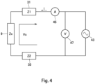
- the calculation unit 51 calculates an impedance based on the voltage Vx output from the voltage detection circuit 47 and a voltage Vy output from the differential-signal detection circuit 49. The procedure for calculating the impedance is described with reference to Fig. 4 .
- Fig. 4 is a diagram showing an equivalent circuit in the case of measuring the impedance.
- the measurement container 10 is used to measure the impedance of the cells 9
- the measurement container 10 is placed on a horizontal base. Then, a cell suspension is dropped onto the bottom 11 of the measurement container 10 on which the first electrodes 31 are arranged. After the cell suspension dropped into the measurement container 10 is left for several minutes, a plurality of cells 9 settle and form a cell layer on the bottom 11 of the measurement container 10.
- the liquid 91 for measurement e.g., culture medium
- the liquid 91 comes in contact with the first electrodes 31 and the second electrode 33 so as to bring the first electrodes 31 and the second electrode 33 into conduction.
- Vy R2 * i ⁇ Vs
- a signal phase difference can be detected by measuring the voltages Vx and Vy, it is possible to measure a composite impedance, i.e., Zx + Z1 + Z2.
- the target impedance Zx can be calculated by subtracting the total value of the contact impedances Z1 and Z2 from the composite impedance of Zx + Z1 + Z2.
- the impedance measurement apparatus 1 is capable of measuring the impedance of the cells 9 serving as a target object, by measuring the current flowing through the first electrodes 31 forming a multielectrode array. Accordingly, it is possible, by using the measurement container 10, which is a multielectrode array device, to measure not only conventional extracellular action potentials but also the impedance of the cells 9.
Landscapes
- Health & Medical Sciences (AREA)
- Life Sciences & Earth Sciences (AREA)
- Engineering & Computer Science (AREA)
- Physics & Mathematics (AREA)
- Chemical & Material Sciences (AREA)
- Biomedical Technology (AREA)
- Analytical Chemistry (AREA)
- Pathology (AREA)
- Immunology (AREA)
- General Physics & Mathematics (AREA)
- General Health & Medical Sciences (AREA)
- Biochemistry (AREA)
- Biophysics (AREA)
- Medicinal Chemistry (AREA)
- Food Science & Technology (AREA)
- Urology & Nephrology (AREA)
- Molecular Biology (AREA)
- Hematology (AREA)
- Optics & Photonics (AREA)
- Chemical Kinetics & Catalysis (AREA)
- Electrochemistry (AREA)
- Investigating Or Analyzing Materials By The Use Of Electric Means (AREA)
- Apparatus Associated With Microorganisms And Enzymes (AREA)
- Measurement And Recording Of Electrical Phenomena And Electrical Characteristics Of The Living Body (AREA)
Abstract
Description
- The subject matter disclosed in the specification of the present invention relates to an impedance measurement apparatus and an impedance measurement method.
- In the field of electrophysiology, analysis is conducted on the activities of a single or a group of cellular ion channels. Examples of known ion channel analyzers include intracellular action potential detectors using a patch-clamp method and extracellular action potential detectors using a multielectrode array (MEA) device. For example, Patent Literature (PTL) 1 discloses a multielectrode array device.
- PTL 1:
Japanese Unexamined Patent Application Publication (Translation of PCT Application) No. 2016-529889 - For example, there may be situations in which the impedance of target biological samples (including cells and biological slices) are measured in order to easily measure changes in cell shape or the density of cells. However, multielectrode array devices have conventionally been used only for the detection of extracellular action potentials, and technology for measuring the impedance of biomaterials by using a multielectrode array device has not yet been found.
- It is an object of the present invention to provide a technique that allows use of a multielectrode array device to measure the impedance of biomaterials.
- To solve the problem described above, a first aspect is an impedance measurement apparatus that includes a measurement container, a plurality of first electrodes arranged in an array on a bottom surface of the measurement container, a second electrode located inside the measurement container, a voltage application circuit that applies a voltage between each of the first electrodes and the second electrode, a current detection circuit that detects current flowing through each of the first electrodes, and a voltage detection circuit that detects a voltage between each of the first electrodes and the second electrode.
- A second aspect is the impedance measurement apparatus according to the first aspect that further includes an electrode selection circuit that selects one first electrode that is to be connected to the current detection circuit, from among the plurality of first electrodes.
- A third aspect is the impedance measurement apparatus according to the first or second aspect, in which the current detection circuit is capable of outputting a voltage responsive to the current. The impedance measurement apparatus further includes a differential-signal detection circuit that detects a difference between an alternating voltage applied by the voltage application circuit and a voltage output from the current detection circuit.
- A fourth aspect is the impedance measurement apparatus according to any one of the first to third aspects that further includes a calculation unit that calculates an impedance in accordance with the current detected by the current detection circuit and the voltage detected by the voltage detection circuit.
- A fifth aspect is an impedance measurement method that includes a) applying an alternating voltage between at least one of a plurality of first electrodes and a second electrode, the plurality of first electrodes being arranged in an array on a bottom surface of a measurement container, the second electrode being located inside the measurement container, b) detecting current flowing through the first electrode(s) while the alternating voltage is applied by the operation a), c) detecting a voltage between the first electrode(s) and the second electrode while the alternating voltage is applied by the operation a), and d) calculating an impedance of a target object in accordance with the current detected by the operation b) and the voltage detected by the operation c).
- The impedance measurement apparatuses according to the first to fourth aspects are capable of measuring the impedance of a target object by a two-terminal method using the first electrodes arranged in an array.
- The impedance measurement apparatus according to the second aspect is capable of measuring the impedance by using one first electrode selected from among the plurality of first electrodes.
- The impedance measurement apparatus according to the third aspect is capable of calculating the impedance of a target object in accordance with a phase difference between the alternating voltage and the current.
-
- [
Fig. 1] Fig. 1 is a diagram schematically showing a configuration of an impedance measurement apparatus according to one embodiment. - [
Fig. 2] Fig. 2 is a perspective view of a measurement container shown inFig. 1 . - [
Fig. 3] Fig. 3 is a top view of the measurement container shown inFig. 1 . - [
Fig. 4] Fig. 4 is a diagram showing an equivalent circuit in the case of measuring an impedance. - Hereinafter, one embodiment of the present invention will be described with reference to the accompanying drawings. Note that constituent elements described in the embodiment are merely examples and are not intended to limit the scope of the present invention. To facilitate understanding of the drawings, the dimensions or number of constituent elements may be illustrated in an exaggerated or simplified manner as necessary.
-
Fig. 1 is a diagram schematically showing a configuration of an impedance measurement apparatus 1 according to an embodiment.Fig. 2 is a perspective view of ameasurement container 10 shown inFig. 1 .Fig. 3 is a top view of themeasurement container 10 shown inFig. 1 . As shown inFig. 1 , the impedance measurement apparatus 1 includes themeasurement container 10 and ameasuring unit 20. - The
measurement container 10 is a container for measuring the impedance ofcells 9 serving as a target object. A cell suspension that contains thecells 9 is dropped into themeasurement container 10. Themeasurement container 10 has abottom 11 and aside wall 13 as shown inFigs. 2 and3 . Thebottom 11 expands in a disk-like shape along a horizontal plane. Theside wall 13 extends upward in a cylindrical shape from the peripheral portion of thebottom 11. Thebottom 11 is an example of a "measurement plate." Thebottom 11 has an upper surface that corresponds to the bottom surface of themeasurement container 10 on
to which the cell suspension is dropped. Note that an object to be measured by themeasurement container 10 is not limited to thecells 9 and may, for example, be a sample of biological tissue slices. - The
measurement container 10 includes a plurality offirst electrodes 31, asecond electrode 33, a plurality offirst wires 35, and asecond wire 37. Thefirst electrodes 31, thesecond electrode 33, thefirst wires 35, and thesecond wire 37 are located on the upper surface of the bottom 11 (the bottom surface of the measurement container 10). Eachfirst wire 35 and thesecond wire 37 are covered with an insulator (e.g., light-sensitive polyimide). For example, eachfirst electrode 31, thesecond electrode 33, eachfirst wire 35, and thesecond wire 37 may be formed by photolithography on the upper surface of thebottom 11. - The
first electrodes 31 are arranged in an array. Themeasurement container 10 is a multielectrode array (or microelectrode array) device that includes the plurality of finefirst electrodes 31 arranged in an array. In the examples shown inFigs. 1 ,2 , and3 , sixteenfirst electrodes 31 are arranged in a matrix with four rows and four columns. Note that the number and layout of thefirst electrodes 31 may be set freely. Preferably, ten or morefirst electrodes 31 may be arranged. Thefirst electrodes 31 have a square shape in a top view. It is, however, noted that the shape of thefirst electrodes 31 may be a shape other than a square shape, such as a polygonal shape or a circular shape. - The
second electrode 33 is located radially outward of and away from thefirst electrodes 31. Thefirst electrodes 31 and thesecond electrode 33 are electrically isolated from each other. In the examples shown inFigs. 1 ,2 , and3 , thesecond electrode 33 has an approximately circular ring-shape with an opening when viewed from above. Thesecond electrode 33 is arranged so as to surround thefirst electrodes 31. Note that the shape of thesecond electrode 33 is not limited to an approximately circular ring-shape and may be any other shape such as a circular shape or a polygonal shape. - It is not essential to locate the
second electrode 33 on the upper surface of thebottom 11. For example, thesecond electrode 33 may be formed in a stick-like shape and configured to be immersed in aliquid 91 that is injected into themeasurement container 10. - Each
first wire 35 is electrically connected to a corresponding one of thefirst electrodes 31. Eachfirst wire 35 extends to the outside of themeasurement container 10. Thefirst wires 35 extend to the outside through the opening of thesecond electrode 33. Thefirst wires 35 and thesecond electrode 33 are electrically isolated from each other. Thesecond wire 37 is electrically connected to thesecond electrode 33. Thesecond wire 37 extends from thesecond electrode 33 to the outside of themeasurement container 10. As shown inFig. 1 , eachfirst wire 35 and thesecond wire 37 are electrically connected to the measuringunit 20 arranged outside themeasurement container 10. - As shown in
Fig. 1 , the measuringunit 20 includes anelectrode selection circuit 41, avoltage application circuit 43, acurrent detection circuit 45, avoltage detection circuit 47, a differential-signal detection circuit 49, and acalculation unit 51. - The
electrode selection circuit 41 is a circuit for selecting onefirst electrode 31 that is to be electrically connected to thecurrent detection circuit 45 and thevoltage detection circuit 47, from among the plurality offirst electrodes 31. As shown inFig. 1 , theelectrode selection circuit 41 includes a plurality of switches that open and close circuits that connect each of thefirst electrodes 31 to thecurrent detection circuit 45. - The
voltage application circuit 43 applies an alternating voltage of a predetermined frequency between thefirst electrode 31 selected by theelectrode selection circuit 41 and thesecond electrode 33. - The
current detection circuit 45 is electrically connected to theelectrode selection circuit 41. Thecurrent detection circuit 45 detects current flowing through onefirst electrode 31 selected by theelectrode selection circuit 41. - As shown in
Fig. 1 , thecurrent detection circuit 45 includes anoperational amplifier 451, afirst resistor 453, and a second resistor 455. The non-inverting input terminal (+) of theoperational amplifier 451 is electrically connected to thevoltage application circuit 43. The inverting input terminal (-) of theoperational amplifier 451 is electrically connected to theelectrode selection circuit 41. Thefirst resistor 453 is located between theelectrode selection circuit 41 and the inverting input terminal (+) of theoperational amplifier 451. One end of the second resistor 455 is connected between the differential-signal detection circuit 49 and an output terminal of theoperational amplifier 451. The other end of the second resistor 455 is connected between thefirst resistor 453 and the inverting input terminal (-) of theoperational amplifier 451. - The
voltage detection circuit 47 detects a voltage Vx between thesecond electrode 33 and onefirst electrode 31 selected by theelectrode selection circuit 41. As shown inFig. 1 , thevoltage detection circuit 47 includes anoperational amplifier 471. The non-inverting input terminal (+) of theoperational amplifier 471 is connected between theelectrode selection circuit 41 and thefirst resistor 453 and is thus electrically connected to onefirst electrode 31 via theelectrode selection circuit 41. The inverting input terminal (-) of theoperational amplifier 471 is electrically connected to thesecond electrode 33. - The differential-
signal detection circuit 49 detects a phase difference between the alternating voltage applied by thevoltage application circuit 43 and the current detected by thecurrent detection circuit 45. As shown inFig. 1 , the differential-signal detection circuit 49 includes anoperational amplifier 491. The non-inverting input terminal (+) of theoperational amplifier 491 is connected to the output terminal of theoperational amplifier 451 of thecurrent detection circuit 45. The inverting input terminal (-) of theoperational amplifier 491 is connected to thevoltage application circuit 43. - The
calculation unit 51 includes a storage device, a processing circuit, an input device, and an output device. The storage device may be configured as, for example, memory (storage medium) such as a hard disk drive (HDD), random-access memory (RAM), read-only memory (ROM), flash memory, volatile or nonvolatile semiconductor memory, a magnetic disk, a flexible disk, an optical disk, a compact disc, a minidisc, or a DVD. The processing circuit may be configured as, for example, a central processing unit - (CPU) that executes programs stored in the storage device. The input device may be configured as, for example, a device that is capable of inputting information, such as a mouse, a keyboard, a touch panel, or a variety of switches. The output device may be configured as, for example, a device that is capable of outputting information, such as a display, a liquid crystal display, or a lamp.
- The
calculation unit 51 calculates an impedance based on the voltage Vx output from thevoltage detection circuit 47 and a voltage Vy output from the differential-signal detection circuit 49. The procedure for calculating the impedance is described with reference toFig. 4 . -
Fig. 4 is a diagram showing an equivalent circuit in the case of measuring the impedance. In the case where themeasurement container 10 is used to measure the impedance of thecells 9, themeasurement container 10 is placed on a horizontal base. Then, a cell suspension is dropped onto the bottom 11 of themeasurement container 10 on which thefirst electrodes 31 are arranged. After the cell suspension dropped into themeasurement container 10 is left for several minutes, a plurality ofcells 9 settle and form a cell layer on the bottom 11 of themeasurement container 10. After the formation of the cell layer, the liquid 91 for measurement (e.g., culture medium) is injected into themeasurement container 10. Then, the liquid 91 comes in contact with thefirst electrodes 31 and thesecond electrode 33 so as to bring thefirst electrodes 31 and thesecond electrode 33 into conduction. - As shown in
Fig. 4 , when thevoltage application circuit 43 has applied an alternating voltage, alternating current i flows through thefirst electrode 31. Thevoltage detection circuit 47 detects the voltage Vx generated between thefirst electrode 31 and thesecond electrode 33. This voltage Vx is expressed by Expression (1) below, where Z1 represents the contact impedance of thefirst electrode 31, Z2 represents the contact impedance of thesecond electrode 33, and Zx represents the impedance of the target object (cells 9).
- Here, the alternating current i is expressed by Expression (2) below, where Vs represents the voltage applied by the
voltage application circuit 43, and R1 represents the resistance value of thefirst resistor 453.
- The voltage Vy output from the differential-
signal detection circuit 49 corresponds to a difference between the applied voltage Vs and the voltage (= R2*i) output from thecurrent detection circuit 45. That is, the voltage Vy is expressed by Expression (3) below.
- Since a signal phase difference can be detected by measuring the voltages Vx and Vy, it is possible to measure a composite impedance, i.e., Zx + Z1 + Z2. A total value of the contact impedances Z1 and Z2 can be measured by impedance measurement conducted in the presence of only the liquid 91 (i.e., no cells 9: Zx = 0). The target impedance Zx can be calculated by subtracting the total value of the contact impedances Z1 and Z2 from the composite impedance of Zx + Z1 + Z2.
- As described above, the impedance measurement apparatus 1 is capable of measuring the impedance of the
cells 9 serving as a target object, by measuring the current flowing through thefirst electrodes 31 forming a multielectrode array. Accordingly, it is possible, by using themeasurement container 10, which is a multielectrode array device, to measure not only conventional extracellular action potentials but also the impedance of thecells 9. - While the invention has been shown and described in detail, the foregoing description is in all aspects for illustration purposes only and not limiting. It is therefore understood that numerous modifications and variations that are not described above can be devised without departing from the scope of the invention. The configurations in the embodiments and variations described above may be appropriately combined or omitted as long as there are no mutual inconsistencies.
-
- 1
- impedance measurement apparatus
- 10
- measurement container
- 11
- bottom
- 20
- measuring unit
- 31
- first electrode
- 33
- second electrode
- 41
- electrode selection circuit
- 43
- voltage application circuit
- 45
- current detection circuit
- 47
- voltage detection circuit
- 49
- differential-signal detection circuit
- 51
- calculation unit
Claims (5)
- An impedance measurement apparatus comprising:a measurement container;a plurality of first electrodes arranged in an array on a bottom surface of the measurement container;a second electrode located inside the measurement container;a voltage application circuit that applies a voltage between each of the first electrodes and the second electrode;a current detection circuit that detects current flowing through each of the first electrodes; anda voltage detection circuit that detects a voltage between each of the first electrodes and the second electrode.
- The impedance measurement apparatus according to claim 1, further comprising:
an electrode selection circuit that selects one first electrode that is to be connected to the current detection circuit, from among the plurality of first electrodes. - The impedance measurement apparatus according to claim 1 or 2, whereinthe current detection circuit is capable of outputting a voltage responsive to the current,the impedance measurement apparatus further comprising:
a differential-signal detection circuit that detects a difference between an alternating voltage applied by the voltage application circuit and a voltage output from the current detection circuit. - The impedance measurement apparatus according to any one of claims 1 to 3, further comprising:
a calculation unit that calculates an impedance in accordance with the current detected by the current detection circuit and the voltage detected by the voltage detection circuit. - An impedance measurement method comprising:a) applying an alternating voltage between at least one of a plurality of first electrodes and a second electrode, the plurality of first electrodes being arranged in an array on a bottom surface of a measurement container, the second electrode being located inside the measurement container;b) detecting current flowing through the first electrode(s) while the alternating voltage is applied by the operation a);c) detecting a voltage between the first electrode(s) and the second electrode while the alternating voltage is applied by the operation a); andd) calculating an impedance of a target object in accordance with the current detected by the operation b) and the voltage detected by the operation c).
Applications Claiming Priority (2)
| Application Number | Priority Date | Filing Date | Title |
|---|---|---|---|
| JP2022070704A JP7854842B2 (en) | 2022-04-22 | 2022-04-22 | Impedance measuring device and impedance measuring method |
| PCT/JP2023/013966 WO2023204018A1 (en) | 2022-04-22 | 2023-04-04 | Impedance measurement apparatus and impedance measurement method |
Publications (2)
| Publication Number | Publication Date |
|---|---|
| EP4513179A1 true EP4513179A1 (en) | 2025-02-26 |
| EP4513179A4 EP4513179A4 (en) | 2026-03-25 |
Family
ID=88419741
Family Applications (1)
| Application Number | Title | Priority Date | Filing Date |
|---|---|---|---|
| EP23791669.7A Pending EP4513179A4 (en) | 2022-04-22 | 2023-04-04 | IMPEDANCE MEASURING DEVICE AND IMPEDANCE MEASURING METHOD |
Country Status (3)
| Country | Link |
|---|---|
| EP (1) | EP4513179A4 (en) |
| JP (1) | JP7854842B2 (en) |
| WO (1) | WO2023204018A1 (en) |
Family Cites Families (9)
| Publication number | Priority date | Publication date | Assignee | Title |
|---|---|---|---|---|
| JPS6131948A (en) * | 1984-07-25 | 1986-02-14 | Toshiba Corp | Instrument for measuring impedance of coated film |
| US6596507B2 (en) * | 2000-04-14 | 2003-07-22 | Nanotec Solution | Device and method for determining characteristic of a biomass |
| EP2213721B1 (en) | 2007-09-18 | 2016-03-02 | Reprocell, Inc. | Cell measuring vessel, extracellular potential measuring method, and chemical testing method |
| JP2012037435A (en) | 2010-08-09 | 2012-02-23 | Hioki Ee Corp | Method and device for detecting cell behavior |
| US9683253B2 (en) | 2013-03-19 | 2017-06-20 | Imec | Method and device for identifying cells |
| JP6570981B2 (en) | 2015-11-24 | 2019-09-04 | 日置電機株式会社 | Measuring apparatus and measuring method |
| US10758151B2 (en) | 2017-01-23 | 2020-09-01 | NovaScan, Inc. | Techniques for detecting cancerous cells in excised tissue samples using impedance detection |
| WO2020189172A1 (en) * | 2019-03-20 | 2020-09-24 | 株式会社Screenホールディングス | Cell holding container and measurement system |
| JP7460110B2 (en) | 2019-11-28 | 2024-04-02 | 学校法人立命館 | Measurement method and device |
-
2022
- 2022-04-22 JP JP2022070704A patent/JP7854842B2/en active Active
-
2023
- 2023-04-04 EP EP23791669.7A patent/EP4513179A4/en active Pending
- 2023-04-04 WO PCT/JP2023/013966 patent/WO2023204018A1/en not_active Ceased
Also Published As
| Publication number | Publication date |
|---|---|
| WO2023204018A1 (en) | 2023-10-26 |
| EP4513179A4 (en) | 2026-03-25 |
| JP2023160373A (en) | 2023-11-02 |
| JP7854842B2 (en) | 2026-05-07 |
Similar Documents
| Publication | Publication Date | Title |
|---|---|---|
| JP3570715B2 (en) | Signal detection sensor with multiple electrodes | |
| US6894511B2 (en) | Extracellular recording multiple electrode | |
| Thein et al. | Response characteristics of single-cell impedance sensors employed with surface-modified microelectrodes | |
| JP6138805B2 (en) | Apparatus and method for recording impedance spectrum and electric field potential in parallel | |
| RU2566605C2 (en) | Device and method of improved measurements by means of inspection device | |
| US9671432B2 (en) | Nanowire electrode sensor | |
| Gillis et al. | Electrochemical measurement of quantal exocytosis using microchips | |
| WO2020189172A1 (en) | Cell holding container and measurement system | |
| US6010889A (en) | Electrochemical noise measurement to assess cellular behavior and metabolic activity | |
| EP1410015B1 (en) | Method and circuitry for controlling and measuring electrical parameters in a biological membrane | |
| US10823722B2 (en) | Probe for measuring the biomass content in a medium | |
| US10837936B2 (en) | Electrochemical measurement system, electrochemical measurement device, and electrochemical measurement method | |
| US8217665B2 (en) | Radio-frequency ion channel probe | |
| EP4513180A1 (en) | Impedance measurement apparatus and impedance measurement method | |
| CN112673252B (en) | Cellular analysis using a CHEMFET sensor array-based system | |
| JP7854842B2 (en) | Impedance measuring device and impedance measuring method | |
| WO2023014437A1 (en) | Electrochemical measurement apparatuses and methods for monitoring and controlling ph | |
| Das et al. | Electrical characterization of suspended HeLa cells using ECIS based biosensor | |
| JP2014124133A (en) | Device and method for measuring extracellular potential | |
| CN106574909B (en) | Contact structure body and electrical measurement device using biological sample contact structure body | |
| EP3591377B1 (en) | Electrochemical determination of the permeability of biological membranes and cellular layers | |
| RU2488104C1 (en) | Method for determination of electrical characteristics and/or identification of biological objects and apparatus for realising said method | |
| US12631593B2 (en) | Electrochemical measurement apparatuses and methods for monitoring and controlling pH | |
| JP3182127U (en) | Extracellular potential measuring apparatus and method | |
| JP2020150854A (en) | Cell retention vessel and measurement system |
Legal Events
| Date | Code | Title | Description |
|---|---|---|---|
| STAA | Information on the status of an ep patent application or granted ep patent |
Free format text: STATUS: THE INTERNATIONAL PUBLICATION HAS BEEN MADE |
|
| PUAI | Public reference made under article 153(3) epc to a published international application that has entered the european phase |
Free format text: ORIGINAL CODE: 0009012 |
|
| STAA | Information on the status of an ep patent application or granted ep patent |
Free format text: STATUS: REQUEST FOR EXAMINATION WAS MADE |
|
| 17P | Request for examination filed |
Effective date: 20241007 |
|
| AK | Designated contracting states |
Kind code of ref document: A1 Designated state(s): AL AT BE BG CH CY CZ DE DK EE ES FI FR GB GR HR HU IE IS IT LI LT LU LV MC ME MK MT NL NO PL PT RO RS SE SI SK SM TR |
|
| DAV | Request for validation of the european patent (deleted) | ||
| DAX | Request for extension of the european patent (deleted) | ||
| A4 | Supplementary search report drawn up and despatched |
Effective date: 20260225 |
|
| RIC1 | Information provided on ipc code assigned before grant |
Ipc: G01N 27/02 20060101AFI20260219BHEP Ipc: C12M 1/34 20060101ALI20260219BHEP Ipc: G01N 33/483 20060101ALI20260219BHEP |