EP4513162A1 - Verfahren und vorrichtung zur automatischen prüfung von gasturbinen - Google Patents
Verfahren und vorrichtung zur automatischen prüfung von gasturbinen Download PDFInfo
- Publication number
- EP4513162A1 EP4513162A1 EP24196298.4A EP24196298A EP4513162A1 EP 4513162 A1 EP4513162 A1 EP 4513162A1 EP 24196298 A EP24196298 A EP 24196298A EP 4513162 A1 EP4513162 A1 EP 4513162A1
- Authority
- EP
- European Patent Office
- Prior art keywords
- test
- engine
- subsystem
- test cell
- fuel
- Prior art date
- Legal status (The legal status is an assumption and is not a legal conclusion. Google has not performed a legal analysis and makes no representation as to the accuracy of the status listed.)
- Pending
Links
Images


Classifications
-
- G—PHYSICS
- G01—MEASURING; TESTING
- G01M—TESTING STATIC OR DYNAMIC BALANCE OF MACHINES OR STRUCTURES; TESTING OF STRUCTURES OR APPARATUS, NOT OTHERWISE PROVIDED FOR
- G01M15/00—Testing of engines
- G01M15/14—Testing gas-turbine engines or jet-propulsion engines
-
- F—MECHANICAL ENGINEERING; LIGHTING; HEATING; WEAPONS; BLASTING
- F02—COMBUSTION ENGINES; HOT-GAS OR COMBUSTION-PRODUCT ENGINE PLANTS
- F02C—GAS-TURBINE PLANTS; AIR INTAKES FOR JET-PROPULSION PLANTS; CONTROLLING FUEL SUPPLY IN AIR-BREATHING JET-PROPULSION PLANTS
- F02C7/00—Features, components parts, details or accessories, not provided for in, or of interest apart form groups F02C1/00 - F02C6/00; Air intakes for jet-propulsion plants
- F02C7/24—Heat or noise insulation
- F02C7/25—Fire protection or prevention
-
- F—MECHANICAL ENGINEERING; LIGHTING; HEATING; WEAPONS; BLASTING
- F02—COMBUSTION ENGINES; HOT-GAS OR COMBUSTION-PRODUCT ENGINE PLANTS
- F02C—GAS-TURBINE PLANTS; AIR INTAKES FOR JET-PROPULSION PLANTS; CONTROLLING FUEL SUPPLY IN AIR-BREATHING JET-PROPULSION PLANTS
- F02C9/00—Controlling gas-turbine plants; Controlling fuel supply in air- breathing jet-propulsion plants
- F02C9/26—Control of fuel supply
- F02C9/46—Emergency fuel control
-
- F—MECHANICAL ENGINEERING; LIGHTING; HEATING; WEAPONS; BLASTING
- F05—INDEXING SCHEMES RELATING TO ENGINES OR PUMPS IN VARIOUS SUBCLASSES OF CLASSES F01-F04
- F05D—INDEXING SCHEME FOR ASPECTS RELATING TO NON-POSITIVE-DISPLACEMENT MACHINES OR ENGINES, GAS-TURBINES OR JET-PROPULSION PLANTS
- F05D2260/00—Function
- F05D2260/80—Diagnostics
-
- F—MECHANICAL ENGINEERING; LIGHTING; HEATING; WEAPONS; BLASTING
- F05—INDEXING SCHEMES RELATING TO ENGINES OR PUMPS IN VARIOUS SUBCLASSES OF CLASSES F01-F04
- F05D—INDEXING SCHEME FOR ASPECTS RELATING TO NON-POSITIVE-DISPLACEMENT MACHINES OR ENGINES, GAS-TURBINES OR JET-PROPULSION PLANTS
- F05D2260/00—Function
- F05D2260/83—Testing, e.g. methods, components or tools therefor
Definitions
- the present disclosure relates to methods and apparatus for testing gas turbine engines.
- New and overhauled aircraft engines are subjected to extensive testing as a prerequisite before being brought into service. Certain tests may be performed with the engine in a nonoperational mode (e.g., no ignition) but other tests are performed while the engine is running in a test cell. Using conventional test procedures, engine operation testing tends to be labor intensive.
- test cell operations are performed by a test cell operator (e.g., a test engineer) that must be present during engine operation to conduct the testing and to collect data. Because certain tests require a substantial amount of time, more than one test cell operator may be tasked with performing the tests. As a result, tests that are performed repetitively may not be performed in the exact same manner each time (human variation) and the test data may be tainted as a result.
- test tests are performed over a significant period time that may exceed the daily working hours of a test engineer or may run beyond a test engineer's work week. In these instances, under conventional practices the testing may be suspended overnight, or over a weekend, or over a holiday, or the like, thereby extending the time frame necessary to perform the testing.
- an automated test cell for testing a gas turbine test engine includes a fuel subsystem, an engine lubrication subsystem, a test cell security subsystem, and a system controller.
- the system controller is in communication with the fuel subsystem, the engine lubrication subsystem, the test cell security subsystem, and a non-transitory memory storing instructions.
- the instructions when executed cause the system controller to: operate the test engine pursuant to a predetermined test cycle, including producing test data; control the engine lubrication subsystem to provide lubrication to the test engine pursuant to the predetermined test cycle; control the fuel subsystem to provide fuel to the test engine pursuant to the predetermined test cycle; control the test cell security subsystem to monitor an environment within the test cell; and report the test data.
- the instructions when executed may cause the system controller to control the test cell security subsystem to monitor the test cell environment for fire.
- the monitoring of the test cell environment for fire may include sensing for combustion gases and/or thermal sensing.
- the instructions when executed may cause the system controller to control the test cell security subsystem to monitor the test cell environment for fuel leakage, and in the event a fuel leakage is detected, may control the fuel subsystem to close down.
- the instructions when executed may cause the system controller to control the test cell security subsystem to monitor the test cell environment for fuel fumes, and in the event said fuel fumes are detected, may control the fuel subsystem to close down.
- the instructions when executed may cause the system controller to control the test cell security subsystem to monitor the test cell environment for fire, and in the event fire is detected the instructions may cause the system controller to control the test cell security subsystem to initiate fire extinguishing steps.
- the fire extinguishing steps may include controlling one or more fire extinguishing devices, and may include controlling the fuel subsystem and the engine lubrication system to close down.
- the automated test cell may include a test cell engine airflow subsystem
- the fire extinguishing steps may include controlling the test cell engine airflow subsystem to stop an influx of air into the test cell in the event fire is detected.
- the automated test cell may include an engine air bleed subsystem, and the instructions when executed may cause the system controller to control the engine air bleed subsystem to bleed gas path air from a compressor section of the test engine during the predetermined test cycle.
- the automated test cell may include an engine load subsystem, and the instructions when executed may cause the system controller to control the engine load subsystem to selectively apply a load to the test engine during the predetermined test cycle.
- a method for testing a gas turbine test engine within a test cell includes: engaging the test engine with a fuel subsystem configured to selectively provide a flow of fuel to the test engine and an engine lubrication subsystem configured to selectively provide a flow of lubricant to the test engine; operating the test engine within the test cell using a system controller that is in communication with the fuel subsystem and the lubrication subsystem, the operation of the test engine using the system controller including operating the test engine according to a predetermined test cycle and producing test data representative of the test engine operation; and monitoring the operation of the test engine within the test cell during the predetermined test cycle using a test cell security subsystem that is in communication with the system controller, wherein the monitoring includes monitoring an environment within the test cell during the predetermined test cycle.
- test engine operation monitoring within the test cell during the predetermined test cycle using a test cell security subsystem may include sensing for combustion gases indicative of a fire.
- the method may include controlling the test cell security subsystem to initiate fire extinguishing steps in the event the monitoring step detects fire, and may include controlling the fuel subsystem and the engine lubrication system to close down in the event of fire, and may include sealing the test cell to stop an influx of air into the test cell in the event of fire.
- the method may include monitoring the test cell for fuel leakage or fuel fumes during the operation of the test engine according to the predetermined test cycle.
- the method may include using the system controller to control an engine air bleed subsystem to bleed gas path air from a compressor section of the test engine during the predetermined test cycle.
- the method may include using the system controller to control an engine load subsystem to apply a load to the test engine during the predetermined test cycle.
- FIG. 1 diagrammatically illustrates an example of a gas turbine engine 20 that may be tested using the present disclosure method and system.
- the gas turbine engine 20 has in serial flow communication a fan section 22, a compressor section 24, a combustor 26, a turbine section 28, and an axial centerline 30.
- the present disclosure may be utilized with a variety of different gas turbine engine types, including turboprop engines, turboshaft engines, turbojet engines, a propfan engines, open rotor engines, auxiliary power units (APU), or the like.
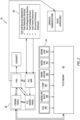
- Embodiments of the present disclosure automated test cell 32 includes a plurality of test cell engine subsystems 34, a security subsystem 36, a system controller 38, and input and output devices.
- the test cell engine subsystems 34 may include one or more of a fuel subsystem 34A, an engine air bleed subsystem 34B, an environmental temperature subsystem (“E-Temp") 34C, an engine airflow subsystem 34D, an engine lubrication subsystem (“Engine Lube”) 34E, and an engine load subsystem 34F, and combinations thereof.
- the listed subsystems 34A-F represent examples of test cell engine subsystems 34 that may be included in the present disclosure test cell 32.
- the present disclosure test cell 32 may include fewer, or more, and/or different engine subsystems 34.
- test engine 40 a gas turbine engine
- the test frame is configured to support the test engine 40 and to keep the test engine 40 substantially stationary relative to the ground.
- the present disclosure is not limited to any particular test frame configuration or other structure for holding the test engine 40.
- the fuel subsystem 34A may include a fuel storage device (e.g., a tank) configure to store a sufficient amount of the type of fuel combusted within the test engine 40.
- the fuel subsystem 34A or the test engine itself may include a pump configured to provide a volumetric flow of fuel from the storage device to the test engine 40.
- the fuel subsystem 34A may include one or more valving / metering devices controllable to provide a desired amount of fuel to the test engine 40 for the operating conditions of the engine; e.g., a fuel flow appropriate for idle when the test engine 40 is operating in an idle state, a fuel flow appropriate for cruise when the test engine 40 is operating in a cruise state, and so on.
- the fuel subsystem 34A may include sensors configured to measure the fuel flow (e.g., measure the volumetric fuel flow rate) during use.
- the fuel subsystem 34A may include safety valving that is configured to shut off the flow of fuel to the test engine 40 in the event of an issue during testing.
- the engine air bleed subsystem 34B may be configured to replicate gas path air bleeding applications so that the present disclosure test cell 32 can replicate actual engine operating conditions.
- Gas turbine engines in normal operation very often include structure for continuously or selectively bleeding air from the gas path of the engine. Air bled from the gas path within the compressor section of the gas turbine engine may be used for a variety of different purposes including use within an aircraft cabin environment control systems, for compressor operability, to provide engine starting air (e.g., produced by an APU), to produce a load on the test engine 40, and the like.
- the engine air bleed subsystem 34B may be configured to replicate at least some of these gas path air bleeding applications so that the engine testing can replicate actual operating conditions.
- the engine air bleed subsystem 34B may be configured to be in fluid communication with the test engine 40 so as to receive bleed air from the test engine 40 at the appropriate ports.
- the engine air bleed subsystem 34B may include downstream valving or the like that alters the downstream flow of the bleed air (e.g., closes the flow entirely or partially) in a manner that replicates gas path air bleeding during takeoff, during ascent, cruise, during descent, and the like.
- the engine air bleed subsystem 34B is configured to control and measure the volumetric rate of airflow being bled from the test engine 40.
- the environmental temperature subsystem (“E-Temp") 34C is configured to create a temperature environment within the test cell 32 that improves the ability of the test cell 32 to operate the test engine 40 during testing; e.g., the environmental temperature subsystem 34C heats or cools the air within the test cell 32 as desired for the test at hand.
- the test cell engine airflow subsystem 34D is configured to handle air intake into and engine exhaust from the test cell 32.
- the intake portion of this subsystem 34D provides the volumetric air requirements for all of the engine operation conditions tested within the test cell 32; e.g., idle, takeoff, cruise, etc.
- the exhaust portion of this subsystem 34D provides structure to handle the exhaust produced by the test engine 40 under all engine operation conditions tested within the test cell 32; e.g., idle, takeoff, cruise, etc.
- Both the intake and exhaust portions may be configured to close in the event of an issue arising during the testing process. For example, in the event a fire is detected within the test cell 32, the intake and the exhaust portions may be closed to prevent an influx of air.
- the apparatus utilized to close the intake and/or exhaust portions may be controlled to coordinate the timing of the closing based on the operating condition of the engine being tested.
- engine lubricant e.g., "oil”
- the lubrication system is configured to provide a lubricant flow to, and recover lubricant from, engine components.
- the lubrication system may include elements that are integral with the engine and may include elements that are independent of, but in communication with, the engine.
- Engine Lube 34E provides those elements (or elements that are functionally equivalent) to enable satisfaction of the lubrication requirements of the test engine 40 for all engine operating conditions tested within the test cell; e.g., idle, takeoff, cruise, etc.
- Engine Lube subsystem 34E may include one or more heat exchangers in communication with a cooling medium sufficient to control the lubricant temperature for all of the aforesaid testing operating conditions.
- Embodiments of the present disclosure engine lubrication subsystem 34E may also include elements necessary to satisfy the lubricant flow requirements of the test engine 40; e.g., elements that provide a flow of lubricant flow to and from the test engine 40 such as a supply pump, a scavenge pump, a tank, a deaerator, valving, and the like, and any combination thereof.
- engine load subsystem 34F is configured to apply a load to the test engine 40 that simulates various engine operating conditions tested within the test cell; e.g., idle, takeoff, cruise, etc.
- the engine load subsystem 34F may be configured to apply a load to the test engine 40 that replicates the load that an electric generator would apply to the test engine 40 during engine operating conditions.
- the test cell security subsystem 36 may include fire detection devices, fire extinguishing devices, fuel leakage sensors, and fuel fume sensors.
- the test cell security subsystem 36 may include personnel presence detectors.
- the fire detection devices may include smoke sensors, combustion gas sensors (e.g., CO2), heat sensors (e.g., thermocouples), optical flame detectors (e.g., "fire eyes"), and the like, or any combination thereof.
- the present disclosure is not limited to any particular fire detection devices other than those suitable to be used in the test cell environment.
- the fire extinguishing devices may include a gaseous environment system configured to fill the test cell 32 with an inert gas that is not combustible.
- the air within the test cell 32 may be replaced with the inert gas.
- the replacement of air with the inert gas will cause the fire to starve from lack of oxygen, and thereby self-extinguish.
- the present disclosure is not limited to any particular fire extinguishing devices other than one that is suitable to be used in the test cell environment.
- the present disclosure is not limited to any particular fuel leakage sensor and/or fuel fume sensors other than those suitable to be used in the test cell environment.
- the test cell security subsystem 36 that include a personnel presence sensing device, the device is configured to sense the presence of a person within the test cell.
- the device may include motion sensors, or cameras, or the like that provide an indication of the presence of a person within the test cell.
- the present disclosure is not limited to any particular type of personnel presence detectors other than one that is suitable to be used in the test cell environment.
- the system controller 38 may include one or more processors in signal communication with a memory device.
- the processor may include any type of computing device, computational circuit, processor(s), CPU, computer, or the like capable of executing a series of instructions that are stored in the memory. Instructions can be directly executable or can be used to develop executable instructions. For example, instructions may be executable or non-executable machine code or a high-level language that can be compiled to produce executable or non-executable machine code, or any combination thereof. Instructions may include data. Instructions may be organized in any format, including routines, subroutines, programs, data structures, objects, modules, applications, applets, functions, etc.
- Instructions may include an operating system, and/or executable software modules such as program files, system data, buffers, drivers, utilities, and the like.
- the instructions may apply to any test cell 32 functionality described herein.
- the memory may include a single memory device or a plurality of memory devices; e.g., a computer-readable storage device that can be read, written, or otherwise accessed by a general purpose or special purpose computing device, including any processing electronics and/or processing circuitry capable of executing instructions.
- the present disclosure is not limited to any particular type of memory device, which may be non-transitory, and may include read-only memory, random access memory, volatile memory, non-volatile memory, static memory, dynamic memory, flash memory, cache memory, volatile or non-volatile semiconductor memory, optical disk storage, magnetic disk storage, magnetic tape, other magnetic storage devices, or any other medium capable of storing one or more instructions, and/or any device that stores digital information.
- the memory device(s) may be integral with the system controller 38 or may be independent of, but in communication with, the system controller 38.
- the system controller 38 may include, or may be in communication with, an input device that enables a user to enter data and/or instructions, and may include, or be in communication with, an output device configured, for example to display information (e.g., a visual display or a printer), or to transfer data, etc.
- the present disclosure test cell embodiment diagrammatically shown in FIG. 2 includes a programmable logic controller smart panel ("PLC smart panel”) and a PLC human-machine interface (“PLC HMI”) that may be configured as input devices, or output devices, or both.
- PLC smart panel programmable logic controller smart panel
- PLC HMI PLC human-machine interface
- the test cell embodiment shown in FIG. 2 also includes a "logsheet” which may be an input/storage device that can be used test personnel to input test data for storage purposes.
- the logsheet may be used to record all of the steps taken during the testing, to record engine and/or test parameters, input from test cell systems and subsystems, operator notes, and the like.
- the input from test cell systems and subsystems may include, for example, input from the various test cell security subsystems (e.g., signals indicating "fire detection devices operational”, “no fuel leakage sensed”, “no fuel fumes sensed”, “test cell temperatures”, and the like) to provide a record of all important parameters occurring during the testing.
- the logsheet may be configured to time stamp all input such that the record is complete as a function of time.
- the test cell 32 embodiment shown in FIG. 2 also includes a block labeled "operator communications" and visual surveillance" in communication with the system controller 38.
- test cell management information e.g., current test cycle, current test data, user control input prompts, and the like
- visual monitoring images of the test cell 32 may be provided.
- the input and/or output devices may be disposed locally with the test cell 32 and/or may be located remotely; e.g., to enable oversight from a remote location.
- the "engine FADEC” block shown in the system controller 38 diagrammatically represents stored instructions as may be provided in the full authority digital engine control (FADEC) used to control the test engine 40 in a given aircraft application.
- the "engine FADEC” block represents instructions that may be used to control the test engine 40 under all engine operating conditions tested within the test cell 32; e.g., idle, takeoff, cruise, and the like.
- the "DAS" block shown in the system controller 38 diagrammatically represents stored instructions directed toward data acquisition. For example, during the testing engine performance data is collected; e.g., temperatures, pressures, rotor speeds, and the like.
- the data acquisition system (“DAS") may be configured to collect and organize that data for subsequent analysis to evaluate the performance of the test engine 40 under the test conditions. Communications within the test cell 32 (e.g., within the system controller 38, or between the system controller 38 and other test cell 32 components may be via a hardwire connection or via a wireless connection.
- portions of the system controller 38 may assume various forms (e.g., digital signal processor, analog device, etc.) capable of performing the functions described herein.
- the functions of the system controller 38 described herein may be performed by an independent system controller 38 or alternatively some or all of the system controller 38 functions may be performed by a plurality of different controllers.
- gas turbine engines may be tested off wing in a test cell to ensure characteristics relating to performance, durability, reliability, and the like.
- the testing may be configured to control and verify engine and engine system functions, verify engine parameters, verify engine reliability and durability, verify engine performance, and the like.
- the testing likely includes a substantial number of testing cycles at different loadings, at different rotational speeds, and the like, performed relative to predetermined codes and standards.
- test cell operations are performed by a test cell operator present at the test cell during testing.
- the testing may include performing tests repeatedly under different parameters and typically takes a substantial amount of time.
- tests may be performed by different test cell operators (which may introduce human variable error) and the test data may be tainted as a result.
- many of the tests are performed over a significant period of time. Testing that is not completed in a given work day or in a given week, may be suspended until the next work day or suspended over the weekend. In some instances, resumption of the testing requires additional time to bring the engine (and/or collateral systems) up to speed for the test at hand.
- the present disclosure automated test cell 32 and method provides a substantial improvement over current test cell systems and practices.
- the present disclosure automated test cell 32 and method permits automated testing that does not require a test cell operator to perform the tests.
- the testing is performed in an automated fashion, and can be performed non-stop (e.g., on a twenty-four hour basis, on traditional workdays, or weekend days, or during holidays, or the like).
- the test engine 40 may be mounted on a test frame within the present disclosure test cell 32.
- various present disclosure subsystems are engaged with the test engine 40.
- the environmental temperature subsystem 34C may be controlled to establish a desired test cell air temperature.
- the environmental temperature subsystem 34C may be controlled to maintain the desired test cell air temperature or to change the test cell air temperature to meet the requirements of the test at hand.
- the fuel subsystem 34A is engaged with the test engine 40 to provide fuel to the combustor section of the test engine 40.
- the system controller 38 controls the fuel subsystem 34A to provide an appropriate flow of fuel at an appropriate point in time.
- the engine air bleed subsystem 34B is engaged with the test engine 40.
- the system controller 38 controls the engine air bleed subsystem 34B to bleed an amount of gas path flow to replicate operating conditions for the specific test at hand; e.g., continuous or selective bleeding of air from the gas path of the test engine 40 to replicate gas path air bleeding during takeoff, during ascent, cruise, during descent, and the like.
- the test engine 40 may be engaged with a device configured to apply a load on the test engine 40.
- the engine load subsystem 34F is controlled to apply an appropriate amount of load at an appropriate time and for an appropriate duration to replicate engine operating conditions during flight segments such as takeoff, ascent, cruise, descent, and the like.
- the security subsystem 36 is engaged and verified; e.g., the security subsystem 36 may be controlled to verify that fire detection devices are properly operating, and fire detection devices are operational, and no fuel leakage or fumes are sensed.
- the personnel presence detector(s) may be operated to verify that the test cell is clear of personnel.
- the system controller 38 may control the present disclosure to run through a pre-test verification sequence (e.g., via stored instructions) that verifies all appropriate subsystems are properly configured and/or operating to perform the testing at hand. Assuming the pre-test verification sequence indicates all appropriate subsystems are operational, then the system controller 38 may start the test engine 40 and run the test engine 40 until the engine arrives at an operational status that is acceptable to begin the testing.
- a pre-test verification sequence e.g., via stored instructions
- the system controller 38 controls the test engine 40 and the respective subsystems in a manner appropriate for each predetermined aspect of the testing at hand.
- a test cell operator may monitor the testing via the output devices in communication with the system controller 38; e.g., locally at the test cell 32 or remotely via communication with the system controller 38.
- the test cell operator may input instructions into the test cell 32 via input device(s) (e.g., a PLC smart panel, a PLC HMI, a remote device in communication with the system controller 38, or the like), but that is not required in the present disclosure automated test cell 32.
- input device(s) e.g., a PLC smart panel, a PLC HMI, a remote device in communication with the system controller 38, or the like
- the automated test cell 32 may be configured so that the security subsystem 36 continuously monitors the present disclosure test cell.
- the automated test cell 32 may be configured so that components of the security subsystem 36 (e.g., fire detection devices like a smoke sensor, a heat sensor, or the like, and/or fuel leakage sensor and/or fuel fume sensors) continuously send sensor data to the system controller 38, and the system controller 38 evaluates that sensor data to determine if any threshold indicative of a problem is met, and the like.
- the sensor data may be stored in memory.
- the automated test cell 32 may be configured so that components of the security subsystem 36 send sensor data to the system controller 38 only when the signal data is indicative of a problem; e.g., a threshold is met. In some embodiments, the automated test cell 32 may be configured to have some combination of continuous reporting and event reporting.
- the system controller 38 is configured to take appropriate action. For example, if an engine malfunction is detected the security subsystem 36 (or other subsystem) may control the fuel subsystem 34A to shut down the flow of fuel and thereby terminate the test. As another example, if a fuel leakage or fuel fumes are detected within the test cell, the fuel subsystem 34A may be controlled to shut down the flow of fuel and thereby terminate the test. As another example, if a lubrication subsystem malfunction is detected within the test cell, the fuel subsystem 34A may be controlled to shut down the flow of fuel and thereby terminate the test.
- the security subsystem 36 may be controlled to automatically a) shut down the flow of fuel; b) close the intake and/or exhaust portions of the test cell 32; c) shut down the engine lubrication system 34E; and d) initiate the fire extinguishing devices.
- the system controller 38 of the present disclosure automated test cell 32 may be controlled to automatically provide communications to the test cell operator regarding the current status of the test cell.
- any one of these structures may describe the operations as a sequential process, many of the operations can be performed in parallel or concurrently.
- the order of the operations may be rearranged.
- a process may correspond to a method, a function, a procedure, a subroutine, a subprogram, etc.
Landscapes
- Engineering & Computer Science (AREA)
- Chemical & Material Sciences (AREA)
- Combustion & Propulsion (AREA)
- Mechanical Engineering (AREA)
- General Engineering & Computer Science (AREA)
- Physics & Mathematics (AREA)
- General Physics & Mathematics (AREA)
- Testing Of Engines (AREA)
Applications Claiming Priority (1)
| Application Number | Priority Date | Filing Date | Title |
|---|---|---|---|
| US18/238,316 US12247897B1 (en) | 2023-08-25 | 2023-08-25 | Method and apparatus for automated gas turbine engine testing |
Publications (1)
| Publication Number | Publication Date |
|---|---|
| EP4513162A1 true EP4513162A1 (de) | 2025-02-26 |
Family
ID=92538575
Family Applications (1)
| Application Number | Title | Priority Date | Filing Date |
|---|---|---|---|
| EP24196298.4A Pending EP4513162A1 (de) | 2023-08-25 | 2024-08-23 | Verfahren und vorrichtung zur automatischen prüfung von gasturbinen |
Country Status (3)
| Country | Link |
|---|---|
| US (1) | US12247897B1 (de) |
| EP (1) | EP4513162A1 (de) |
| CA (1) | CA3253230A1 (de) |
Citations (6)
| Publication number | Priority date | Publication date | Assignee | Title |
|---|---|---|---|---|
| EP1288644A2 (de) * | 2001-08-31 | 2003-03-05 | General Electric Company | Verfahren und System zur Diagnose von Turbinenmotoren |
| EP2006655A2 (de) * | 2007-06-20 | 2008-12-24 | Pratt & Whitney Canada Corp. | Flugzeugmotoren-Vorausrüstungseinheit für eine Testeinrichtung |
| EP2722511A2 (de) * | 2012-10-16 | 2014-04-23 | General Electric Company | Turbinenleckerkennungssystem |
| US20170216637A1 (en) * | 2016-01-28 | 2017-08-03 | Safran Aero Boosters Sa | Test cell for an aircraft turbine engine |
| US20180283200A1 (en) * | 2017-03-28 | 2018-10-04 | Honeywell International Inc. | Gas turbine engine and test cell real-time diagnostic fault detection and corrective action system and method |
| CN111426482A (zh) * | 2020-05-06 | 2020-07-17 | 湖南汉能科技有限公司 | 一种航空发动机燃烧室试验台 |
Family Cites Families (6)
| Publication number | Priority date | Publication date | Assignee | Title |
|---|---|---|---|---|
| US4821217A (en) | 1987-01-12 | 1989-04-11 | The Boeing Company | Programmable jet engine test station |
| US5293775A (en) * | 1992-11-02 | 1994-03-15 | United Technologies Corporation | Gas turbine engine test cell |
| US6138081A (en) | 1998-04-09 | 2000-10-24 | Cmr Technologies, Inc. | Data acquisition system and method for monitoring gas turbine engine testing |
| EP2762852A1 (de) | 2013-02-05 | 2014-08-06 | Siemens Aktiengesellschaft | Selbstprüfungssystem für eine Gasturbine |
| US9915224B2 (en) * | 2015-04-02 | 2018-03-13 | Symbrium, Inc. | Engine test cell |
| US10809156B2 (en) | 2016-02-15 | 2020-10-20 | General Electric Company | Automated system and method for generating engine test cell analytics and diagnostics |
-
2023
- 2023-08-25 US US18/238,316 patent/US12247897B1/en active Active
-
2024
- 2024-08-22 CA CA3253230A patent/CA3253230A1/en active Pending
- 2024-08-23 EP EP24196298.4A patent/EP4513162A1/de active Pending
Patent Citations (6)
| Publication number | Priority date | Publication date | Assignee | Title |
|---|---|---|---|---|
| EP1288644A2 (de) * | 2001-08-31 | 2003-03-05 | General Electric Company | Verfahren und System zur Diagnose von Turbinenmotoren |
| EP2006655A2 (de) * | 2007-06-20 | 2008-12-24 | Pratt & Whitney Canada Corp. | Flugzeugmotoren-Vorausrüstungseinheit für eine Testeinrichtung |
| EP2722511A2 (de) * | 2012-10-16 | 2014-04-23 | General Electric Company | Turbinenleckerkennungssystem |
| US20170216637A1 (en) * | 2016-01-28 | 2017-08-03 | Safran Aero Boosters Sa | Test cell for an aircraft turbine engine |
| US20180283200A1 (en) * | 2017-03-28 | 2018-10-04 | Honeywell International Inc. | Gas turbine engine and test cell real-time diagnostic fault detection and corrective action system and method |
| CN111426482A (zh) * | 2020-05-06 | 2020-07-17 | 湖南汉能科技有限公司 | 一种航空发动机燃烧室试验台 |
Also Published As
| Publication number | Publication date |
|---|---|
| US20250067626A1 (en) | 2025-02-27 |
| CA3253230A1 (en) | 2025-06-03 |
| US12247897B1 (en) | 2025-03-11 |
Similar Documents
| Publication | Publication Date | Title |
|---|---|---|
| JP6403690B2 (ja) | ガスタービンのための自動テストシステム | |
| EP1722072A2 (de) | Verfahren und Vorrichtung zur Bestimmung der Lebensdauer von einem Element einer Maschine | |
| GB2518893A (en) | Method for predicting an auxiliary power unit fault | |
| EP4527744A1 (de) | Wasserstoffleckerkennungssystem für ein flugzeugantriebssystem | |
| EP4345258A1 (de) | Systeme und verfahren zur bestimmung von gasturbinenmotortemperaturen | |
| US12247897B1 (en) | Method and apparatus for automated gas turbine engine testing | |
| CA3105230A1 (en) | Method and system for controlling operation of an engine using an engine controller | |
| EP4332708A1 (de) | Motorsteuerungssystem und verfahren mit sensortraining mit künstlicher intelligenz | |
| EP4653671A1 (de) | Motorölsystem für ein flugzeugantriebssystem und verfahren zur steuerung davon | |
| RU2817575C1 (ru) | Способ контроля теплового состояния электронного регулятора газотурбинного двигателя | |
| US20240060426A1 (en) | Systems and methods for determining gas turbine engine operating margins | |
| EP4461650A1 (de) | System und verfahren zur erkennung der blockierung eines lufteinlasses für ein flugzeugantriebssystem | |
| US12392255B2 (en) | Systems and methods for determining gas turbine engine operating margins | |
| EP4520666A1 (de) | Flugzeugtriebwerksanordnung zur steuerung des motorölflusses bei brandbedingungen und verfahren zur verwendung davon | |
| US12535016B2 (en) | Systems and methods for identifying insufficient starter acceleration for an aircraft engine | |
| Mei et al. | Research on real-time simulation test method for functional requirement design verification of civil aircraft auxiliary power source | |
| US20250051021A1 (en) | Loss of load path detection system for aircraft propulsion system nacelle and method for using same | |
| Neporozhniy et al. | GRAPHIC SUPPORT FOR THE OPERATION OF AIRCRAFT POWER UNITS. | |
| Peitsch | Modelling the transient behaviour of jet engines | |
| Xinlei et al. | Civil aircraft engine start system health monitoring method based on QAR data | |
| Bolivar et al. | Advanced Propulsion System Simulation Model for a Modern Fighter Aircraft Training Aid | |
| Speth et al. | F15/F100 engine diagnostic system | |
| Brenner | On-board checkout approach to engine diagnostics-It can work | |
| Meador et al. | Advance Airborne System for Maintenance Monitoring | |
| Lekki et al. | Vehicle Integrated Propulsion Research for the Study of Health Management Capabilities |
Legal Events
| Date | Code | Title | Description |
|---|---|---|---|
| PUAI | Public reference made under article 153(3) epc to a published international application that has entered the european phase |
Free format text: ORIGINAL CODE: 0009012 |
|
| STAA | Information on the status of an ep patent application or granted ep patent |
Free format text: STATUS: THE APPLICATION HAS BEEN PUBLISHED |
|
| AK | Designated contracting states |
Kind code of ref document: A1 Designated state(s): AL AT BE BG CH CY CZ DE DK EE ES FI FR GB GR HR HU IE IS IT LI LT LU LV MC ME MK MT NL NO PL PT RO RS SE SI SK SM TR |
|
| STAA | Information on the status of an ep patent application or granted ep patent |
Free format text: STATUS: REQUEST FOR EXAMINATION WAS MADE |
|
| 17P | Request for examination filed |
Effective date: 20250826 |