EP4513146B1 - Rotary sensor - Google Patents
Rotary sensor Download PDFInfo
- Publication number
- EP4513146B1 EP4513146B1 EP23192499.4A EP23192499A EP4513146B1 EP 4513146 B1 EP4513146 B1 EP 4513146B1 EP 23192499 A EP23192499 A EP 23192499A EP 4513146 B1 EP4513146 B1 EP 4513146B1
- Authority
- EP
- European Patent Office
- Prior art keywords
- permanent magnets
- magnet arrangement
- sensor
- operating device
- magnet
- Prior art date
- Legal status (The legal status is an assumption and is not a legal conclusion. Google has not performed a legal analysis and makes no representation as to the accuracy of the status listed.)
- Active
Links
Images


Classifications
-
- G—PHYSICS
- G01—MEASURING; TESTING
- G01D—MEASURING NOT SPECIALLY ADAPTED FOR A SPECIFIC VARIABLE; ARRANGEMENTS FOR MEASURING TWO OR MORE VARIABLES NOT COVERED IN A SINGLE OTHER SUBCLASS; TARIFF METERING APPARATUS; MEASURING OR TESTING NOT OTHERWISE PROVIDED FOR
- G01D5/00—Mechanical means for transferring the output of a sensing member; Means for converting the output of a sensing member to another variable where the form or nature of the sensing member does not constrain the means for converting; Transducers not specially adapted for a specific variable
- G01D5/12—Mechanical means for transferring the output of a sensing member; Means for converting the output of a sensing member to another variable where the form or nature of the sensing member does not constrain the means for converting; Transducers not specially adapted for a specific variable using electric or magnetic means
- G01D5/14—Mechanical means for transferring the output of a sensing member; Means for converting the output of a sensing member to another variable where the form or nature of the sensing member does not constrain the means for converting; Transducers not specially adapted for a specific variable using electric or magnetic means influencing the magnitude of a current or voltage
- G01D5/142—Mechanical means for transferring the output of a sensing member; Means for converting the output of a sensing member to another variable where the form or nature of the sensing member does not constrain the means for converting; Transducers not specially adapted for a specific variable using electric or magnetic means influencing the magnitude of a current or voltage using Hall-effect devices
- G01D5/145—Mechanical means for transferring the output of a sensing member; Means for converting the output of a sensing member to another variable where the form or nature of the sensing member does not constrain the means for converting; Transducers not specially adapted for a specific variable using electric or magnetic means influencing the magnitude of a current or voltage using Hall-effect devices influenced by the relative movement between the Hall device and magnetic fields
Definitions
- the present application relates to a rotary sensor comprising a magnet arrangement and to a method of assembling a rotary sensor.
- Rotary sensors can be used for angular or rotational measurements.
- Hall-sensors may for example be employed for contactless angular measurements which are particularly suitable for harsh environments.
- a disc or ring magnet having a number of poles is mounted to the rotating equipment and the rotation of the magnetic field is detected by the Hall-sensor.
- plural sensor elements including Hall-sensor pairs may be employed, which can be provided on a single integrated circuit.
- ring magnets may be employed which have four sectors, each sector being magnetized axially, wherein neighboring sectors have an opposite direction of magnetization. Two north poles and two south poles may accordingly be provided on each axial face of the ring magnet.
- Such magnets are generally produced by using injection molding of magnetizable material mixed with thermoplastic material (with a filling degree of up to 85%).
- a Hall-sensor can be arranged opposite to the annular axial face of such ring magnet at a predefined distance thereto.
- the sensor element is generally offset in a radial direction to be exposed to a relatively large z-component of the magnetic field, in particular of the magnetic flux density Bz.
- a radial displacement for example due to mechanical drift, mechanical wear, or mechanical vibrations, may result in a deviation of an angle of rotation measured by the Hall-sensor.
- the document EP 3 543 657 A1 suggests the providing of grooves between the sectors of the ring magnet, which is formed of a single monolithic piece of material.
- the grooves provide a constant magnetic field gradient in a central region around the axis of the magnet. Such shaping of the magnetic field reduces the angular position error.
- the ring magnet has to maintain a minimum flux density, which requires particularly large ring magnets when produced with the conventional injection molding methods. A magnetization of the magnetic material may further become difficult or may not even be possible below a certain size of the ring magnet.
- the document EP 3 244 167 A1 describes a magnetic component for a Hall effect sensor of an electric supercharger of a combustion engine.
- the magnetic component includes four magnets distributed around the axis of a body. Additional magnets are provided for increasing the rising fronts of magnet sensor signals to improve the accuracy of detecting the rotation speed above 10,000 rpm.
- the document US 5,831,596 A describes a joystick controller having a resilient arm with a tube and a handle.
- the arm flexes around a pivot point, wherein a position of a magnet mounted to the tube affects an output of Hall effect probes.
- Such magnet arrangement may allow the rotary sensor to become more compact.
- the degree of magnetization and thus the magnetic flux density that can be generated by the magnet arrangement may be increased significantly.
- such distinct permanent magnets may be made more compact and may be arranged closer to, e.g., a shaft of the component, so that the size required by the magnet arrangement may be reduced. Mounting of the magnet arrangement to the component may thus be facilitated, as it may be easier to feed the magnet arrangement through a small space or aperture. Contrary to the general perception, it has further been found that with such arrangement, the robustness of the rotary sensor against misalignment between the magnet arrangement and the magnetic field sensor may further be improved.
- the rotary sensor may thus provide an improved measurement accuracy and may further be more robust against mechanical vibrations and/or mechanical drift, e.g. due to bearing play. Further, by providing a higher magnetic flux density, the rotary sensor may be more robust against disturbing external magnetic fields, such as homogeneous and inhomogeneous magnetic fields.
- the magnet arrangement comprises at least four distinct and spatially separate permanent magnets arranged circumferentially about the rotational axis. It may comprise exactly four distinct and spatially separate permanent magnets arranged circumferentially about the rotational axis. In other configurations, it may comprise even more permanent magnets, such as at least six or exactly six, at least eight or exactly eight, or the like.
- the component may comprise a shaft or protrusion extending in the axial direction, and the magnet arrangement may be mountable to the shaft or protrusion.
- the magnet arrangement may comprise an inner recess or hole that extends on the rotation axis in the axial direction and that may be configured to receive such shaft (e.g., a shaft end) of the component.
- the at least four permanent magnets may be spaced apart from each other in circumferential direction.
- a distance by which the at least four permanent magnets are spaced apart from each other in circumferential direction may be less than 6 mm, less than 3 mm, less than 2 mm, or less than 1.5 mm. With such spacing, a deviation of an angle measurement by the rotary sensor due to a displacement of the magnetic field sensor may thereby be minimized.
- the optimal spacing between the neighboring permanent magnets will generally depend on the size of the permanent magnets and may thus be chosen accordingly.
- the spacing relates to the spacing between the outer perimeter of the permanent magnets, i.e. the minimum distance between the outer surfaces of neighboring permanent magnets.
- north and south poles alternate in circumferential direction.
- the permanent magnet may in particular be a bar magnet or a rod magnet, with its magnetic poles on the opposite axial end faces.
- the at least one magnetic field sensor may comprise at least one Hall-sensor arranged in the axial direction on a side of the magnet element that is opposite to a side on which the magnet element is configured to receive or to be mounted to the component (e.g. to receive a shaft).
- a sensor element of the Hall-sensor may be offset from the rotation axis in a radial direction that is perpendicular to the axial direction.
- a Hall-sensor may comprise one or plural different Hall-sensor elements to measure different directions of the magnetic field and/or to compensate for external magnetic fields.
- the sensor element of the Hall sensor may be a sensor array.
- the Hall sensor may comprise 1, 2 or more respective sensor arrays.
- a sensor array may form a circle, e.g. a Hall plate circle. The center of such Hall plate circle may be offset from the axis in said radial direction, for example by less than 5 mm, less than 3 mm, or less than 2 mm.
- the Hall-sensor may be provided as a single chip or single integrated circuit on which a number of Hall-sensor elements is provided. Depending on the arrangement, the Hall-sensor may comprise a vertical Hall-device.
- the Hall-sensor may in particular be provided as a sensor chip that comprises the one or more sensor elements and electronics configured to evaluate signals measured by the sensor element(s) and to give out a signal that indicates the angular orientation of the magnetic field or of the rotary shaft.
- the rotary sensor may comprise plural magnetic field sensors, for example plural Hall-sensors arranged at different positions relative to the magnet arrangement.
- the rotary sensor may comprise one or more Hall-sensors arranged radially adjacent to the magnet arrangement, for example to measure a radial or tangential component of the magnetic flux density.
- Such arrangements are similarly suitable for providing an accurate indication of the rotational state or rotational speed of the magnet arrangement and thus of a component to which it is mounted.
- the rotary sensor may be a rotation angle sensor configured to detect an angle of rotation of the component and/or a rotational speed sensor configured to detect a rotational speed of the component.
- the permanent magnets may be rare-earth magnets, such as Sm 2 Co 17 magnets.
- the permanent magnets each have a magnetic remanence of at least 400 mT, preferably at least 600 mT or at least 800 mT.
- a sufficiently strong magnetic field for detection by the magnetic field sensor may thus be provided.
- the magnet arrangement may be configured to provide an axial component of a magnetic flux density (Bz) of at least 10 mT, preferably at least 12 mT or at least 15 mT at a position in a plane perpendicular to the axial direction, wherein the plane is spaced apart from the magnet arrangement in axial direction by at least 1 mm or at least 2 mm.
- Bz magnetic flux density
- the magnetic flux density may be higher or may be lower; however, it must achieve in the plane at least the defined minimum magnetic flux density.
- the plane may in particular be a plane in which the magnetic field sensor is arranged, in particular a sensor element of the Hall-sensor (such as sensitive semiconductor slab of the Hall-sensor).
- the magnetic flux density is generally designated as the B-field and is measured in Tesla (T).
- the rotary sensor may further comprise a housing configured to house the at least four permanent magnets.
- the housing may be configured to be mounted to the component in a non-rotatable manner. Such housing may accordingly fix the relative positioning of the permanent magnets relative to each other and may further fix their positioning with respect to the component. A stable, reliable and reproducible magnetic field may thereby be provided in the rotary sensor.
- the housing may comprise a recess configured to receive a shaft of the component.
- the shaft may be received in the housing and the shaft may have opening into which a pin is mounted, e.g. screwed or pressed, wherein the pin secures the housing on the shaft, e.g. via a head of the pin.
- the housing may include a recess configured to receive such head of the pin. A compact configuration may thereby be achieved.
- the housing may additionally or alternatively comprise a support member for each permanent magnet.
- the support member may be configured to hold the respective permanent magnet.
- the support member may hold the permanent magnet by clamping, by using an interference fit, and/or the housing may have a cover configured to close the housing after insertion of the permanent magnets into the respective support members in order to secure the permanent magnets within the housing.
- the housing may additionally or alternatively comprise an interlocking feature configured to receive a complementary interlocking feature of the component in a form-fitting manner, e.g. to mitigate or prevent a rotation of the housing with respect to the shaft or component.
- the interlocking feature of the shaft may be a shaft end having a non-circular shape
- the interlocking feature of the housing may include a recess having a shape that is complementary to the shape of the end of the shaft to enable the engagement of the shaft and the housing in a form-fitting manner.
- the recess is formed by a central cut-away section of the housing that exposes lateral side walls of the at least four permanent magnets, and the end of the shaft may be formed to engage the cut-away section in a form fitting manner; it may in particular be configured to abut the respective side wall sections of the at least four permanent magnets.
- the interlocking features may alternatively be configured as a slot and key arrangement, e.g. for a circular shaft or shaft end. A compact configuration which at the same time provides protection against relative rotation may thus be achieved.
- Other ways of non-rotatably mounting the magnet arrangement to the shaft are certainly conceivable, such as a pin configured to engage the shaft, a clamping member, gluing, soldering, welding or the like.
- an angular deviation of a measurement by the rotary sensor caused by a radial displacement (with respect to the rotational axis) of the magnetic sensor element may be at least 15%, preferably at least 25%, 35%, or 45%, lower than an angular deviation of a measurement caused by a respective radial displacement of a rotary sensor comprising such ring magnet and the same or a similar magnetic sensor element.
- the reduction may for example be achieved at a radial displacement of 10% of the diameter of the permanent magnets (e.g., at 0.3 mm for permanent magnets of 3 mm diameter).
- the configuration of the rotary sensor may thus reduce such deviation of an angular measurement significantly. Measurement accuracy may thereby be improved, in particular in harsh environments in which the rotary sensor is exposed to vibration, thermal cycling, or other environmental influences that may have a negative impact on measuring accuracy and that may, in conventional sensors, for example result in sensor drift.
- the component, and in particular the shaft, may form part of the rotary sensor.
- an operating device for a mobile machine comprising a pivotable handle and a detection mechanism coupled to the pivotable handle.
- the detection mechanism comprises a component that is rotated about an axis upon pivoting the handle.
- the operating device further comprises a rotary sensor having any of the configurations described herein.
- the magnet arrangement of the rotary sensor is mounted to the component of the operating device detect a rotation of the component.
- a reliable and precise control of the machine may be enabled by such operating device.
- the operating device can be made durable and well suited for use in harsh environments.
- the operating device may for example be a joystick control device.
- the operating device may have a suspension that rotates about the axis about which the handle pivots, and the component may be mounted to or may form part of such suspension.
- the handle may be mounted by a gimbal mount, and the component may be mounted to or may form part of a respective gimbal.
- a precise detection of the degree of pivoting of the handle becomes possible.
- such operating device may comprise plural respective rotary sensors, e.g. one or two for each direction of pivoting/rotation.
- a method of assembling a rotary sensor comprises providing a magnet arrangement configured to generate a magnetic field, wherein the magnet arrangement comprises at least four distinct and seatially separate permanent magnets. wherein the at least four permanent magnets are arranged circumferentially about a rotation axis extending in an axial direction, and wherein the magnet arrangement is configured to be non-rotatably mounted to a component a rotation of which about the rotational axis is to be measured.
- the method may further comprise arranging at least one magnetic field sensor adjacent to the magnet arrangement to detect a rotation of the magnetic field generated by the magnet arrangement upon rotation of the magnet arrangement.
- the method may further comprise mounting the magnet arrangement non-rotatably to the component, e.g. to a rotatable shaft thereof that extends in the axial direction.
- the rotary sensor may thus be enabled to provide a precise measurement of the component's angular position and/or rotational speed.
- the method may comprise further steps for assembling a rotary sensor having any of the configurations described herein.
- the rotary sensor may be assembled by any of the methods disclosed herein.
- Fig. 1 schematically illustrates a rotary sensor 10 including a magnet arrangement 20 that is configured to generate a magnetic field.
- the magnet arrangement 20 comprises four permanent magnets 21, 22, 23, and 24, which are arranged circumferentially around the rotation axis 15. Axis 15 extends in an axial direction perpendicular to the drawing plane.
- the magnet arrangement 20 is configured to be mounted to a rotating component, such as a rotating shaft, which rotates together with the magnet arrangement about the rotation axis 15.
- the magnet arrangement is rotationally symmetric with respect to rotation axis 15.
- the magnetization of the permanent magnets 21 to 24 is parallel to the axial direction of the axis 15.
- the direction of magnetization alternates between neighboring permanent magnets.
- the permanent magnets 21, 23 present a north pole at their respective axial end, whereas the permanent magnets 22, 24 present a south pole at their respective axial end.
- the magnetic poles have naturally the opposite polarity, meaning that permanent magnets 21, 23 present a south pole, whereas permanent magnets 22 and 24 present a north pole.
- the magnet arrangement 20 thus has four pole pairs and presents four magnetic poles on each end face.
- the permanent magnets 21 to 24 are preferably spaced apart from each other.
- the spacing 25 between neighboring permanent magnets is illustrated in Fig. 1 and is the same for each pair of neighboring permanent magnets. An equal spacing is preferred to maintain symmetry of the generated magnetic field.
- the permanent magnets 21 to 24 further have the same shape and size. In the present example, they have a cylindrical shape, as also shown in Fig. 2 . In the top view of Fig. 1 , they accordingly have a circular end face.
- the periphery, or outer edge, of the permanent magnets 21 to 24 abuts the inner circle 11.
- the permanent magnets 21 to 24 are thus equally spaced apart from the central axis 15. Further, the perimeter of the permanent magnets 21 to 24 abuts the outer circle 12, in particular as the permanent magnets have the same size, in particular the same diameter. In a plane perpendicular to the rotation axis 15, as shown in Fig. 1 , the permanent magnets 21 to 24 are thus arranged within an annular surface bounded by the inner circle 11 and the outer circle 12. These dimensions may be employed for a comparison with a corresponding ring-shaped magnet having a respective inner and outer diameter 11, 12.
- the diameter of the cylindrically shaped permanent magnets is 3 mm.
- the height 26 ( figure 2 ) of the permanent magnets may also be 3 mm.
- permanent magnets 21 to 24 are shown in the embodiments of Figs. 1 and 2 , any other even number of permanent magnets may be employed as well, such as six, eight, or more permanent magnets. Further, to tune the magnetic field generated by magnet arrangement 20, it is also conceivable to provide permanent magnets of differing sizes and/or shapes. Further, the permanent magnets do not need to be cylindrical, but may have any desirable shape, such as a polygonal shape, e.g. a rectangular, pentagonal, or other cross-section. Permanent magnets 21 to 24 may for example be rod magnets or bar magnets, with the magnetic poles at the respective axial ends.
- Sensor element 31 (and optional further sensor elements 32) of magnetic field sensor 30 is radially offset from rotation axis 15 by a distance 36.
- Respective Hall-sensors comprising one or more sensor elements 31, 32 are commercially available as single chip solutions, and any respective configuration may be employed here.
- the magnetic field sensor 30 can provide a precise measurement of the rotation of the magnet arrangement 20 around the axis 15. Such angular measurement may be disturbed by a radial displacement between the magnetic arrangement 20 and the magnetic field sensor 30, i.e. a relative displacement in left/right direction or in a direction perpendicular to the drawing plane. Such displacement may for example occur due to mechanical vibrations of component 50, wear, or other external mechanical influences.
- a compact configuration can be achieved, since the inner circle 11 can be made small, while the permanent magnets 21 to 24 can still provide a relatively high magnetic field, and in particular a high magnetic flux density Bz in axial direction at the position of the magnetic field sensor 30. Since the permanent magnets can be pre-magnetized prior to their assembly into the magnet arrangement 20, there is no minimum size requirement on the magnet arrangement 20 while a high degree of magnetization can still be ensured.
- the arrangement illustrated in Figs. 1 and 2 may in particular achieve a magnetic flux density of more than 10 mT at a distance 35 of more than 1 mm.
- the error in the measurement of the rotation angle i.e. the angular deviation
- Such displacement may for example be due to bearing play and/or vibrations.
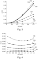
- Fig. 3 shows the angular deviation d ⁇ on the vertical axis and shows the mechanical radial displacement dr on the horizontal axis.
- Curve 301 shows that for a perfect 4-pole cylinder magnet, there is almost no angular deviation.
- Curve 302 illustrates the angular deviation for the magnet arrangement 20 (four permanent magnets of 3 mm diameter and 3 mm height).
- Curve 303 illustrates the angular deviation for a corresponding ring magnet having an outer diameter of 8.5 mm and an inner diameter of 2.5 mm and a height of 3 mm (thus corresponding to the ring between circles 11 and 12 shown in Fig. 1 ).
- the magnet arrangement 20 has a significantly improved reaction to a mechanical displacement in a radial direction dr (direction 36 in figure 7 ) compared to a ring magnet of corresponding size. Using similar dimensions, an improvement by a factor of 2 can be achieved.
- the angular deviation d ⁇ increases.
- the angular deviation d ⁇ has a minimum at a magnet spacing 25 of about 1.1 mm. This observation allows the optimization of the magnet arrangement and making the rotary sensor more robust against radial displacements.
- Fig. 5 illustrates a housing 40 that may form part of the rotary sensor 10 and that is provided for taking up the permanent magnets 21 to 24.
- the housing 40 may comprise a support member 43 for each permanent magnet, which may be provided in form of a sleeve or recess into which the permanent magnet can be inserted in a formfitting manner or may be pressed in.
- the recess 42 opens the view on the permanent magnets 21 to 24 which are arranged within the respective supports 43.
- the housing 40 may further comprise an opening 41 configured to receive a pin (60 in Fig. 7 ) in a formfitting manner.
- Housing 40 further comprises a circumferential outer wall 46 and an axial end cover 45. End cover 45 secures the permanent magnets 21 to 24 in their respective support 43.
- a corresponding end cover may be provided on the opposite axial end of the housing 40.
- Housing 40 may be formed of a single integral piece of material. It may be formed by molding and/or machining.
- the support 43 may comprise a clamping feature, such as a ridge, rib, or protrusion 47 to ensure that when the permanent magnet is pressed into the support 43, the permanent magnet is held firmly in place.
- a clamping feature such as a ridge, rib, or protrusion 47 to ensure that when the permanent magnet is pressed into the support 43, the permanent magnet is held firmly in place.
- Three such ridges or protrusions 47 spaced apart circumferentially by about 120° or another angle may be provided in each support 43.
- the housing 40 may be configured to receive a part of the component 50, such as a shaft 51 ( figure 7 ), a protrusion, or the like.
- Figure 6 illustrates a respective receiving section 48 of housing 40.
- the receiving section 48 has a cross-shaped cross section, which provides an interlocking feature.
- the shaft 51 may have a complementary shape to provide a corresponding interlocking feature.
- the cross-shaped end of the shaft thus engages the receiving section 48 in a form-fitting manner. Interlocking is thereby achieved, and the housing 40 is prevented from being rotated relative to the shaft 51.
- the non-rotatable mount to component 50 may also be achieved in different ways, such as using a slot and key arrangement, using locking pins extending laterally through housing and shaft, using a pin engaging the outer walls of the housing, e.g. the recess shown in the sidewall 46 of figure 5 , or the like.
- a pin 60 may be provided ( figure 7 ) which engages a opening in the shaft.
- the pin 60 may extend through the hole 41 and may have a head larger than hole 41.
- the pin may be pressed into or screwed into the end of shaft 51 so that the housing is pressed against the end of the shaft and cannot become disengaged from the shaft.
- a simple but secure and compact way of mounting housing 40 to shaft 51 may thus be achieved.
- the housing 40 may have a recess 42 configured to take up the head of a respective pin. The assembly may thus be made even more compact.
- Figure 7 illustrates an embodiment of rotary sensor 10 that may be for example be mounted in an operating device 100, e.g. of a mobile machine.
- an operating device may include a handle (not shown) to be operated by an operator; it may have a joystick-like configuration.
- Component 50 forms part of the operating device and is coupled to the handle such that if the handle is actuated, in particular pivoted, the component 50 is rotated about the rotation axis 15.
- Component 50 can form part of a suspension or can be mounted to such suspension.
- a gimbal of a gimbal mount may support the handle and may rotate about the axis 15 when the handle is pivoted, and the component 50 may form part of such gimbal or may be mounted to such gimbal.
- the housing 40 supports the permanent magnets 21-24, two of which are partly visible in the schematic sectional view of figure 7 .
- the section shown in figure 7 does not go through the center of the permanent magnets 21, 23, thus showing a wider section through shaft 51 and through the outer wall 46 of housing 40.
- the housing 40 is secured by pin 60 to the end of shaft 51.
- the component 50 may not comprise a shaft, but the housing may directly be mounted to a differently shaped part of component 50, e.g. to the flat disc-shaped part.
- the magnetic field sensor 30 includes the Hall sensor element 31, and may include one or more additional Hall sensor elements 32.
- Hall sensor element 31 is offset by an offset 36 from the axis 15. The offset may be measured to a center of Hall sensor element 31.
- the Hall sensor element 31 may include a sensor array, which may have the form of a Hall plate circle. The center of such Hall plate circle may form the center of the Hall sensor element 31.
- the offset may for example be about half the diameter of such Hall plate circle.
- Magnetic field sensor 30 may be provided as a (single) chip, such as a Micronas HAR 3930 type stray field robust Hall sensor.
- the chip may include two or more hall sensor elements at different positions on the chip.
- the magnetic field sensor may be spaced apart from the magnet arrangement 20, in particular from the permanent magnets 21-24, by a distance 35 in axial direction (z-direction).
- the distance may be measured to the surface of the chip, the distance of the sensor element 31 from the chip surface being generally known.
- the distance 35 may be more than 1 mm or more than 2 mm.
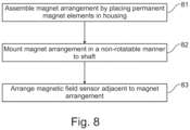
- Fig. 8 illustrates a method of assembling a rotary sensor, which may have any of the configurations described herein.
- the magnet arrangement is assembled by placing the permanent magnets 21 to 24 in the housing 40.
- the magnet arrangement is mounted in a non-rotatable manner to the shaft 51 of component 50 (or to another part of the component).
- the magnetic field sensor 30 is arranged adjacent to the magnet arrangement 20. It should be clear that this is only an exemplary implementation of the method, and that the steps may have a different order and that additionally steps may be provided.
- the rotary sensor 10 may first be assembled as a unit and may then be mounted to the component 50 by attaching the magnet arrangement 20 in a non-rotatable manner to the shaft 51.
Landscapes
- Physics & Mathematics (AREA)
- General Physics & Mathematics (AREA)
- Transmission And Conversion Of Sensor Element Output (AREA)
Description
- The present application relates to a rotary sensor comprising a magnet arrangement and to a method of assembling a rotary sensor.
- Rotary sensors can be used for angular or rotational measurements. Hall-sensors may for example be employed for contactless angular measurements which are particularly suitable for harsh environments. Conventionally, a disc or ring magnet having a number of poles is mounted to the rotating equipment and the rotation of the magnetic field is detected by the Hall-sensor. To account for external disturbing magnetic fields, plural sensor elements including Hall-sensor pairs may be employed, which can be provided on a single integrated circuit.
- As an example, ring magnets may be employed which have four sectors, each sector being magnetized axially, wherein neighboring sectors have an opposite direction of magnetization. Two north poles and two south poles may accordingly be provided on each axial face of the ring magnet. Such magnets are generally produced by using injection molding of magnetizable material mixed with thermoplastic material (with a filling degree of up to 85%).
- A Hall-sensor can be arranged opposite to the annular axial face of such ring magnet at a predefined distance thereto. The sensor element is generally offset in a radial direction to be exposed to a relatively large z-component of the magnetic field, in particular of the magnetic flux density Bz. In such configuration, a radial displacement, for example due to mechanical drift, mechanical wear, or mechanical vibrations, may result in a deviation of an angle of rotation measured by the Hall-sensor. To reduce such deviation, the document
EP 3 543 657 A1 suggests the providing of grooves between the sectors of the ring magnet, which is formed of a single monolithic piece of material. The grooves provide a constant magnetic field gradient in a central region around the axis of the magnet. Such shaping of the magnetic field reduces the angular position error. - It is difficult to make such rotary sensor more compact while maintaining a good measuring accuracy. To be robust against disturbing magnetic fields, the ring magnet has to maintain a minimum flux density, which requires particularly large ring magnets when produced with the conventional injection molding methods. A magnetization of the magnetic material may further become difficult or may not even be possible below a certain size of the ring magnet.
- The document
EP 3 244 167 A1 describes a magnetic component for a Hall effect sensor of an electric supercharger of a combustion engine. The magnetic component includes four magnets distributed around the axis of a body. Additional magnets are provided for increasing the rising fronts of magnet sensor signals to improve the accuracy of detecting the rotation speed above 10,000 rpm. - The document
US 5,831,596 A describes a joystick controller having a resilient arm with a tube and a handle. The arm flexes around a pivot point, wherein a position of a magnet mounted to the tube affects an output of Hall effect probes. - The document
US 2003/0178290 A1 describes an operating unit with a rotary toggle. On the rotary toggle, five signaling magnets are provided that migrate over a Hall sensor to generate signals from which a rotation can be characterized. - The document
US 2015/0253876 A1 discloses a rotary actuator with a coding element having four permanent magnets each being provided as quarter ring section to form a ring, wherein the ring sections are magnetized in a direction that lies in the ring plane. - Accordingly, there is a need to mitigate at least some of the drawbacks mentioned above and to provide an improved rotary sensor, in particular a more compact sensor that provides an improved measuring accuracy.
- This need is met by the features of the independent claims. The dependent claims describe embodiments of the invention.
- According to an embodiment of the invention, a rotary sensor comprising a magnet arrangement configured to generate a magnetic field is provided. The magnet arrangement comprises at least four distinct and spatially separate permanent magnets, wherein the at least four permanent magnets are arranged circumferentially about a rotation axis extending in an axial direction. The magnet arrangement is configured to be non-rotatably mounted to a component a rotation of which about the rotation axis is to be measured. The rotary sensor further comprises at least one magnetic field sensor configured and arranged to detect a rotation of the magnetic field generated by the magnet arrangement upon rotation of the magnet arrangement, e.g. due to rotation of the component.
- Such magnet arrangement may allow the rotary sensor to become more compact. By providing distinct permanent magnets in the magnet arrangement, the degree of magnetization and thus the magnetic flux density that can be generated by the magnet arrangement may be increased significantly. Furthermore, such distinct permanent magnets may be made more compact and may be arranged closer to, e.g., a shaft of the component, so that the size required by the magnet arrangement may be reduced. Mounting of the magnet arrangement to the component may thus be facilitated, as it may be easier to feed the magnet arrangement through a small space or aperture. Contrary to the general perception, it has further been found that with such arrangement, the robustness of the rotary sensor against misalignment between the magnet arrangement and the magnetic field sensor may further be improved. The rotary sensor may thus provide an improved measurement accuracy and may further be more robust against mechanical vibrations and/or mechanical drift, e.g. due to bearing play. Further, by providing a higher magnetic flux density, the rotary sensor may be more robust against disturbing external magnetic fields, such as homogeneous and inhomogeneous magnetic fields.
- According to the invention, the magnet arrangement comprises at least four distinct and spatially separate permanent magnets arranged circumferentially about the rotational axis. It may comprise exactly four distinct and spatially separate permanent magnets arranged circumferentially about the rotational axis. In other configurations, it may comprise even more permanent magnets, such as at least six or exactly six, at least eight or exactly eight, or the like. The component may comprise a shaft or protrusion extending in the axial direction, and the magnet arrangement may be mountable to the shaft or protrusion. The magnet arrangement may comprise an inner recess or hole that extends on the rotation axis in the axial direction and that may be configured to receive such shaft (e.g., a shaft end) of the component. Such recess or hole may have a shape adapted to the shape of the shaft or may simply be a bore, e.g. a through-bore or a dead bore. Such recess or hole may be configured to engage the shaft or component in a formfitting manner, e.g. using an interference fit or a loose fit. A non-circular shape of the recess and shaft, a slot and key arrangement, an interference fit, or the like may be provided for ensuring that the magnet arrangement is not rotatable with respect to the component when mounted to the component.
- The at least four permanent magnets may be spaced apart from each other in circumferential direction. By providing a spacing between the permanent magnets, robustness against magnetic field sensor displacements and sensor accuracy may further be improved. For example, a distance by which the at least four permanent magnets are spaced apart from each other in circumferential direction may be less than 6 mm, less than 3 mm, less than 2 mm, or less than 1.5 mm. With such spacing, a deviation of an angle measurement by the rotary sensor due to a displacement of the magnetic field sensor may thereby be minimized. It should be clear that the optimal spacing between the neighboring permanent magnets will generally depend on the size of the permanent magnets and may thus be chosen accordingly. The spacing relates to the spacing between the outer perimeter of the permanent magnets, i.e. the minimum distance between the outer surfaces of neighboring permanent magnets.
- According to the invention, each permanent magnet has a direction of magnetization that is substantially parallel to the axial direction. Permanent magnets that are neighbors in the circumferential direction have an opposite direction of magnetization. An even number of permanent magnets may thus be provided. Substantially parallel may mean parallel or an angle of less than 10°, 5° or 1° between the respective axes.
- Each permanent magnet may for example extend in the axial direction and may have at one axial end a magnetic north pole and at the other axial end a magnetic south pole, by which the direction of magnetization of the permanent magnet is defined.
- According to the invention, at an axial end face of the magnet arrangement, north and south poles alternate in circumferential direction.
- The permanent magnet may in particular be a bar magnet or a rod magnet, with its magnetic poles on the opposite axial end faces.
- Each permanent magnet may have a cylindrical shape, and a cylinder axis of the cylindrical shape may be substantially parallel to the axial direction. Cylinder axis generally refers to the central symmetry axis of a cylinder in height direction. By such arrangement of cylindrical permanent magnets, a compact configuration that at the same time provides a high magnetic flux density and robustness against radial magnet sensor displacements may be provided.
- In an embodiment, the at least four permanent magnets may be arranged such that in a cross-sectional plane perpendicular to the axial direction, the perimeter (i.e., the external surface) of each of the at least four permanent magnets abuts the same inner circle. Such symmetric arrangement may improve the homogeneity of the field gradients and may facilitate mounting to a central shaft. The perimeter of the permanent magnets may in particular be tangential to the inner circle. For a cylindrical shape of the magnets, which correspond to a circle in the cross-sectional plane, the circular perimeter of each permanent magnet may thus touch or be tangential to the inner circle. In some implementations, the perimeter of each of the at least four permanent magnets may abut the same outer circle. If the permanent magnets are of the same or similar size and shape, they may abut both, the inner circle and the outer circle.
- The inner circle may for example have a diameter of less than 6 mm, less than 4 mm, less than 3.5 mm, or less than 3 mm. A compact rotary sensor may thus be achieved. In particular, such compact size may not be achievable by conventional ring magnets.
- The spacing between neighboring permanent magnets may be the same. The arrangement of the permanent magnets in circumferential direction may in particular be rotationally symmetric (e.g., with respect to a 180 degree rotation, i.e. a 2-fold symmetry).
- The at least four permanent magnets may have the same or a similar size and shape. The diameter of each permanent magnet may be less than 8 mm, less than 5 mm, or less than 4 mm. An extension in axial direction may be less than 8 mm, less than 5 mm, or less than 4 mm. A compact magnet arrangement and thus a compact rotary sensor may thereby be provided. In some implementations, the diameter and the extension in axial direction of the permanent magnets may be similar or the same.
- In an embodiment, a magnetic field sensor is provided in an end-of-shaft configuration. A high measurement accuracy and robustness against external magnetic fields may thereby be achieved.
- For example, the at least one magnetic field sensor may comprise at least one Hall-sensor arranged in the axial direction on a side of the magnet element that is opposite to a side on which the magnet element is configured to receive or to be mounted to the component (e.g. to receive a shaft). A sensor element of the Hall-sensor may be offset from the rotation axis in a radial direction that is perpendicular to the axial direction.
- It should be clear that a Hall-sensor may comprise one or plural different Hall-sensor elements to measure different directions of the magnetic field and/or to compensate for external magnetic fields. The sensor element of the Hall sensor may be a sensor array. The Hall sensor may comprise 1, 2 or more respective sensor arrays. A sensor array may form a circle, e.g. a Hall plate circle. The center of such Hall plate circle may be offset from the axis in said radial direction, for example by less than 5 mm, less than 3 mm, or less than 2 mm.
- The Hall-sensor may be provided as a single chip or single integrated circuit on which a number of Hall-sensor elements is provided. Depending on the arrangement, the Hall-sensor may comprise a vertical Hall-device. The Hall-sensor may in particular be provided as a sensor chip that comprises the one or more sensor elements and electronics configured to evaluate signals measured by the sensor element(s) and to give out a signal that indicates the angular orientation of the magnetic field or of the rotary shaft.
- It should be clear that the rotary sensor may comprise plural magnetic field sensors, for example plural Hall-sensors arranged at different positions relative to the magnet arrangement. For example, additionally or alternatively, the rotary sensor may comprise one or more Hall-sensors arranged radially adjacent to the magnet arrangement, for example to measure a radial or tangential component of the magnetic flux density. Such arrangements are similarly suitable for providing an accurate indication of the rotational state or rotational speed of the magnet arrangement and thus of a component to which it is mounted.
- The rotary sensor may be a rotation angle sensor configured to detect an angle of rotation of the component and/or a rotational speed sensor configured to detect a rotational speed of the component.
- The permanent magnets may be rare-earth magnets, such as Sm2Co17 magnets.
- Preferably, the permanent magnets each have a magnetic remanence of at least 400 mT, preferably at least 600 mT or at least 800 mT. A sufficiently strong magnetic field for detection by the magnetic field sensor may thus be provided.
- The magnet arrangement may be configured to provide an axial component of a magnetic flux density (Bz) of at least 10 mT, preferably at least 12 mT or at least 15 mT at a position in a plane perpendicular to the axial direction, wherein the plane is spaced apart from the magnet arrangement in axial direction by at least 1 mm or at least 2 mm. It should be clear that at other positions of the plane, the magnetic flux density may be higher or may be lower; however, it must achieve in the plane at least the defined minimum magnetic flux density. By such configuration, it may be ensured that the magnetic flux density is sufficiently high so that an accurate measurement of the rotation of the magnet field can be achieved even in the presence of disturbing external magnetic fields.
- The plane may in particular be a plane in which the magnetic field sensor is arranged, in particular a sensor element of the Hall-sensor (such as sensitive semiconductor slab of the Hall-sensor). The magnetic flux density is generally designated as the B-field and is measured in Tesla (T).
- The rotary sensor may further comprise a housing configured to house the at least four permanent magnets. The housing may be configured to be mounted to the component in a non-rotatable manner. Such housing may accordingly fix the relative positioning of the permanent magnets relative to each other and may further fix their positioning with respect to the component. A stable, reliable and reproducible magnetic field may thereby be provided in the rotary sensor.
- The housing may comprise a recess configured to receive a shaft of the component. To fix the housing to the shaft, the shaft may be received in the housing and the shaft may have opening into which a pin is mounted, e.g. screwed or pressed, wherein the pin secures the housing on the shaft, e.g. via a head of the pin. The housing may include a recess configured to receive such head of the pin. A compact configuration may thereby be achieved.
- The housing may additionally or alternatively comprise a support member for each permanent magnet. The support member may be configured to hold the respective permanent magnet. The support member may hold the permanent magnet by clamping, by using an interference fit, and/or the housing may have a cover configured to close the housing after insertion of the permanent magnets into the respective support members in order to secure the permanent magnets within the housing.
- The housing may additionally or alternatively comprise an interlocking feature configured to receive a complementary interlocking feature of the component in a form-fitting manner, e.g. to mitigate or prevent a rotation of the housing with respect to the shaft or component. For example, the interlocking feature of the shaft may be a shaft end having a non-circular shape, and the interlocking feature of the housing may include a recess having a shape that is complementary to the shape of the end of the shaft to enable the engagement of the shaft and the housing in a form-fitting manner. Preferably, the recess is formed by a central cut-away section of the housing that exposes lateral side walls of the at least four permanent magnets, and the end of the shaft may be formed to engage the cut-away section in a form fitting manner; it may in particular be configured to abut the respective side wall sections of the at least four permanent magnets. The interlocking features may alternatively be configured as a slot and key arrangement, e.g. for a circular shaft or shaft end. A compact configuration which at the same time provides protection against relative rotation may thus be achieved. Other ways of non-rotatably mounting the magnet arrangement to the shaft are certainly conceivable, such as a pin configured to engage the shaft, a clamping member, gluing, soldering, welding or the like.
- In an embodiment, compared to a ring magnet having an outer diameter and an inner diameter (measured perpendicular to the rotation axis) of the same size as an outer circle and an inner circle that abut an outer perimeter and an inner perimeter of each of the permanent magnets of the magnet arrangement, respectively, an angular deviation of a measurement by the rotary sensor caused by a radial displacement (with respect to the rotational axis) of the magnetic sensor element may be at least 15%, preferably at least 25%, 35%, or 45%, lower than an angular deviation of a measurement caused by a respective radial displacement of a rotary sensor comprising such ring magnet and the same or a similar magnetic sensor element. The reduction may for example be achieved at a radial displacement of 10% of the diameter of the permanent magnets (e.g., at 0.3 mm for permanent magnets of 3 mm diameter). The configuration of the rotary sensor may thus reduce such deviation of an angular measurement significantly. Measurement accuracy may thereby be improved, in particular in harsh environments in which the rotary sensor is exposed to vibration, thermal cycling, or other environmental influences that may have a negative impact on measuring accuracy and that may, in conventional sensors, for example result in sensor drift.
- The component, and in particular the shaft, may form part of the rotary sensor.
- According to the invention, an operating device for a mobile machine is provided, wherein the operating device comprises a pivotable handle and a detection mechanism coupled to the pivotable handle. The detection mechanism comprises a component that is rotated about an axis upon pivoting the handle. The operating device further comprises a rotary sensor having any of the configurations described herein. The magnet arrangement of the rotary sensor is mounted to the component of the operating device detect a rotation of the component. A reliable and precise control of the machine may be enabled by such operating device. Further, by employing detection of the orientation of the magnetic field, and thus a contactless measurement, the operating device can be made durable and well suited for use in harsh environments. The operating device may for example be a joystick control device.
- The operating device may have a suspension that rotates about the axis about which the handle pivots, and the component may be mounted to or may form part of such suspension. For example, the handle may be mounted by a gimbal mount, and the component may be mounted to or may form part of a respective gimbal. Thus, by mounting the magnet arrangement directly or indirectly to such gimbal, a precise detection of the degree of pivoting of the handle becomes possible. It should be clear that such operating device may comprise plural respective rotary sensors, e.g. one or two for each direction of pivoting/rotation.
- According to a further embodiment of the present invention, a method of assembling a rotary sensor is provided. The method comprises providing a magnet arrangement configured to generate a magnetic field, wherein the magnet arrangement comprises at least four distinct and seatially separate permanent magnets. wherein the at least four permanent magnets are arranged circumferentially about a rotation axis extending in an axial direction, and wherein the magnet arrangement is configured to be non-rotatably mounted to a component a rotation of which about the rotational axis is to be measured. The method may further comprise arranging at least one magnetic field sensor adjacent to the magnet arrangement to detect a rotation of the magnetic field generated by the magnet arrangement upon rotation of the magnet arrangement. By such method, advantages similar to the ones outlined further above may be achieved.
- The method may further comprise mounting the magnet arrangement non-rotatably to the component, e.g. to a rotatable shaft thereof that extends in the axial direction. The rotary sensor may thus be enabled to provide a precise measurement of the component's angular position and/or rotational speed.
- The method may comprise further steps for assembling a rotary sensor having any of the configurations described herein. Furthermore, the rotary sensor may be assembled by any of the methods disclosed herein.
- It is to be understood that the features mentioned above and those yet to be explained below can be used not only in the respective combinations indicated, but also in other combinations or in isolation, without leaving the scope of the present invention. In particular, the features of the different aspects and embodiments of the invention can be combined with each other unless noted to the contrary.
- The foregoing and other features and advantages of the invention will become further apparent from the following detailed description read in conjunction with the accompanying drawings. In the drawings, like reference numerals refer to like elements.
-
Fig. 1 is a schematic drawing showing a top view of a magnet arrangement of a rotary sensor according to an embodiment. -
Fig. 2 is a schematic drawing showing a perspective view of a magnet arrangement of a rotary sensor according to an embodiment. -
Fig. 3 is a diagram schematically illustrating an angular deviation in dependence on a radial displacement of a magnetic field sensor. -
Fig. 4 is a diagram schematically illustrating an angular deviation in dependence on a spacing between permanent magnets for different radial displacements of a magnetic field sensor. -
Fig. 5 is a schematic drawing showing a perspective view of a housing of a magnet arrangement of a rotary sensor according to an embodiment. -
Fig. 6 is a schematic drawing showing a perspective view of a housing of a magnet arrangement of a rotary sensor according to an embodiment. -
Fig. 7 is a schematic drawing showing a sectional view of a rotary sensor according to an embodiment. -
Fig. 8 is a flow diagram illustrating a method of assembling a rotary sensor according to an embodiment. - In the following, embodiments of the invention will be described in detail with reference to the accompanying drawings. It is to be understood that the following description of the embodiments is given only for the purpose of illustration and is not to be taken in a limiting sense. It should be noted that the drawings are to be regarded as being schematic representations only, and elements in the drawings are not necessarily to scale with each other. Rather, the representation of the various elements is chosen such that their function and general purpose become apparent to a person skilled in the art. As used herein, the singular forms "a," "an," and "the" are intended to include the plural forms as well, unless the context clearly indicates otherwise. The terms "comprising," "having," "including," and "containing" are to be construed as openended terms (i.e., meaning "including, but not limited to,") unless otherwise noted.
-
Fig. 1 schematically illustrates arotary sensor 10 including amagnet arrangement 20 that is configured to generate a magnetic field. Themagnet arrangement 20 comprises fourpermanent magnets rotation axis 15.Axis 15 extends in an axial direction perpendicular to the drawing plane. Themagnet arrangement 20 is configured to be mounted to a rotating component, such as a rotating shaft, which rotates together with the magnet arrangement about therotation axis 15. The magnet arrangement is rotationally symmetric with respect torotation axis 15. - In the embodiment of
Fig. 1 , the magnetization of thepermanent magnets 21 to 24 is parallel to the axial direction of theaxis 15. The direction of magnetization alternates between neighboring permanent magnets. On the axial end face of themagnet arrangement 20 shown inFig. 1 , thepermanent magnets permanent magnets magnet arrangement 20, the magnetic poles have naturally the opposite polarity, meaning thatpermanent magnets permanent magnets magnet arrangement 20 thus has four pole pairs and presents four magnetic poles on each end face. By usingsuch magnet arrangement 20 for detecting a rotation about theaxis 15, homogeneous and inhomogeneous external magnetic fields can be compensated by using a magnetic field sensor comprising plural sensor elements. - As illustrated in
Fig. 1 , thepermanent magnets 21 to 24 are preferably spaced apart from each other. The spacing 25 between neighboring permanent magnets is illustrated inFig. 1 and is the same for each pair of neighboring permanent magnets. An equal spacing is preferred to maintain symmetry of the generated magnetic field. Thepermanent magnets 21 to 24 further have the same shape and size. In the present example, they have a cylindrical shape, as also shown inFig. 2 . In the top view ofFig. 1 , they accordingly have a circular end face. - The periphery, or outer edge, of the
permanent magnets 21 to 24 abuts theinner circle 11. Thepermanent magnets 21 to 24 are thus equally spaced apart from thecentral axis 15. Further, the perimeter of thepermanent magnets 21 to 24 abuts theouter circle 12, in particular as the permanent magnets have the same size, in particular the same diameter. In a plane perpendicular to therotation axis 15, as shown inFig. 1 , thepermanent magnets 21 to 24 are thus arranged within an annular surface bounded by theinner circle 11 and theouter circle 12. These dimensions may be employed for a comparison with a corresponding ring-shaped magnet having a respective inner andouter diameter - The diameter di of the
inner circle 11 may for example be less than 4 mm, e.g. less than 3.5 or even less than 3 mm. In the present example, the diameter is di=2.5 mm. The diameter do of theouter circle 12 may be less than 15 mm, preferably less than 12 mm, or even less than 10 mm. In the present example, it is do=8.5 mm. The diameter of the cylindrically shaped permanent magnets is 3 mm. Themagnet spacing 25 between neighboring permanent magnets is in the present example dm=0.9 mm. As an example, the height 26 (figure 2 ) of the permanent magnets may also be 3 mm. -
Fig. 2 is a perspective view of themagnet arrangement 20 ofFig. 1 . As can be seen, thepermanent magnets 21 to 24 are distributed circumferentially around theaxis 15 and abut theinner circle 11. The figure further illustrates theextension 26 in axial direction of the permanent magnets, i.e. the height of the respective cylindrical shapes. Theheight 26 may be of a comparable dimension as the diameter of the cylindrical shapes. - The
magnet arrangement 20 is configured to be mounted to a rotatable component, in particular to a rotating shaft, in a non-rotating manner (i.e. it is fixed to the respective shaft). For mounting to the shaft, themagnet arrangement 20 may comprise a housing to support thepermanent magnets 21 to 24, as explained in more detail further below with respect toFig. 5 . - Although four
permanent magnets 21 to 24 are shown in the embodiments ofFigs. 1 and 2 , any other even number of permanent magnets may be employed as well, such as six, eight, or more permanent magnets. Further, to tune the magnetic field generated bymagnet arrangement 20, it is also conceivable to provide permanent magnets of differing sizes and/or shapes. Further, the permanent magnets do not need to be cylindrical, but may have any desirable shape, such as a polygonal shape, e.g. a rectangular, pentagonal, or other cross-section.Permanent magnets 21 to 24 may for example be rod magnets or bar magnets, with the magnetic poles at the respective axial ends. - Turning briefly to
Fig. 7 , therotary sensor 10 further includes amagnetic field sensor 30 that is arranged adjacent to themagnet arrangement 20 and that may be or may comprise a Hall-sensor. Themagnetic field sensor 30 is arranged opposite to an axial end face of themagnet arrangement 20 to measure a z-component of the magnetic flux density generated by themagnet arrangement 20, the z-direction being parallel to therotation axis 15. Themagnetic field sensor 30 is spaced apart in axial direction from themagnet arrangement 20 by adistance 35.Magnetic field sensor 30 may comprise one or more Hall-sensor elements magnetic field sensor 30 is radially offset fromrotation axis 15 by adistance 36. Respective Hall-sensors comprising one ormore sensor elements - By measuring the magnetic flux density, and thus the rotation thereof, the
magnetic field sensor 30 can provide a precise measurement of the rotation of themagnet arrangement 20 around theaxis 15. Such angular measurement may be disturbed by a radial displacement between themagnetic arrangement 20 and themagnetic field sensor 30, i.e. a relative displacement in left/right direction or in a direction perpendicular to the drawing plane. Such displacement may for example occur due to mechanical vibrations ofcomponent 50, wear, or other external mechanical influences. - In the above example, a compact configuration can be achieved, since the
inner circle 11 can be made small, while thepermanent magnets 21 to 24 can still provide a relatively high magnetic field, and in particular a high magnetic flux density Bz in axial direction at the position of themagnetic field sensor 30. Since the permanent magnets can be pre-magnetized prior to their assembly into themagnet arrangement 20, there is no minimum size requirement on themagnet arrangement 20 while a high degree of magnetization can still be ensured. The arrangement illustrated inFigs. 1 and 2 may in particular achieve a magnetic flux density of more than 10 mT at adistance 35 of more than 1 mm. - Furthermore, magnet material may be conserved compared to a corresponding ring magnet. In a ring magnet, the magnetic material needs to be provided in the whole area of the ring-bounded by the inner and
outer circles permanent magnets 21 to 24 and comparing it to the volume of a ring magnet of the respective size, it turns out that the volume of the four permanent magnets is only 54.6% of the volume of a respective ring magnet. Significant savings in magnetic material may thus be achieved. As noted above, it is however generally not possible to provide a respective ring magnet having the same compactness as themagnet arrangement 20. - The following table compares the volume of magnetic material Vmagnet and the maximum axial magnetic flux density component Bzmax at a
radial displacement 36 of r = 1.125 mm for themagnet arrangement 20 ofFigs. 1 and 2 with differently sized ring magnets, each having a height of 3 mm. The magnetic remanence is Br = 930mT for all magnets. As can be seen, compared to conventional ring magnets, thepresent magnet arrangement 20 provides a relatively high magnetic flux density component Bz at a relatively low volume of magnet material.Table 1 Magnet arrangement 20 (4 magnets 3mm x 3 mm) Ring with di=2.5 mm Ring with di=4 mm Ring with di=4 mm Ring with di=4 mm do=8.5 mm do=9 mm do=12 mm do=15 mm Bzmax 17.5 mT 22.5 mT 16.6 mT 19.1mT 19.7 mT Vmagnet 85 mm3 157 mm3 153 mm 3302 mm3 492 mm3 Ratio [mT/mm3] 0.207 0.141 0.108 0.063 0.040 - In particular, it can be seen that the ratio of Bz/V is the largest for the
magnet arrangement 20. Compared to the best ring magnet, the reduction of magnet material is thus 32% for the same magnetic field at r = 1.125 mm. It is noted that the ring magnet with di=2.5 mm may not even be technically feasible, as outlined above. - By the
magnet arrangement 20, the error in the measurement of the rotation angle (i.e. the angular deviation) that may be caused by the above-mentioned mechanical displacement in radial direction between themagnet arrangement 20 and themagnetic field sensor 30 can be reduced significantly. Such displacement may for example be due to bearing play and/or vibrations. This is illustrated inFig. 3 , which shows the angular deviation dα on the vertical axis and shows the mechanical radial displacement dr on the horizontal axis.Curve 301 shows that for a perfect 4-pole cylinder magnet, there is almost no angular deviation.Curve 302 illustrates the angular deviation for the magnet arrangement 20 (four permanent magnets of 3 mm diameter and 3 mm height).Curve 303 illustrates the angular deviation for a corresponding ring magnet having an outer diameter of 8.5 mm and an inner diameter of 2.5 mm and a height of 3 mm (thus corresponding to the ring betweencircles Fig. 1 ). The remanence for both, themagnet arrangement 20 and the corresponding ring magnet is Br = 930 mT. As can be seen by comparing the curves, themagnet arrangement 20 has a significantly improved reaction to a mechanical displacement in a radial direction dr (direction 36 infigure 7 ) compared to a ring magnet of corresponding size. Using similar dimensions, an improvement by a factor of 2 can be achieved. -
Curve 304 corresponds to a ring magnet withouter diameter 15 mm, inner diameter 4 mm and height 3 mm;curve 305 corresponds to a ring magnet ofouter diameter 12 mm, inner diameter 4 mm and height 3 mm; andcurve 306 corresponds to a ring magnet of outer diameter 9 mm, inner diameter 4 mm, and height 3 mm, all with the same magnetic remanence of 930 mT. Compared to these ring magnets, it can be seen that the reaction to a radial displacement of the magnetic field sensor is even further improved formagnet arrangement 20, e.g. by a factor of 4 or more (for a displacement value dr = 0.3 mm). It is noted for a different magnetic remanence of the ring magnets of, e.g., 420 mT, the respective curves lie essentially behind the curves shown inFig. 3 , which illustrates that the magnetic remanence has not much effect on the angular deviation caused by a relative radial displacement of the magnetic field sensor. Ring magnets with an inner diameter of smaller than 4 mm, i.e. corresponding tocurve 302, and the required magnetic flux density are difficult to produce as outlined above. -
Fig. 4 illustrates the effect of different magnet spacings dm on angular displacement. The angular displacement dα is shown on the vertical axis. The horizontal axis shows the distance dm between adjacent permanent magnets 21-24 in mm, i.e. thedistance 25 shown infigure 1 . The distance dm is the same between each pair or neighboring permanent magnets.Curve 401 corresponds to a displacement of dr=0.1 mm;curve 402 to dr=0.2 mm;curve 403 to dr=0.3 mm;curve 404 to dr=0.4 mm; andcurve 405 to dr=0.5 mm. As expected fromFig. 3 , for a larger radial displacement dr, the angular deviation dα increases. As can be seen, the angular deviation dα has a minimum at a magnet spacing 25 of about 1.1 mm. This observation allows the optimization of the magnet arrangement and making the rotary sensor more robust against radial displacements. - For
Figs. 3 and 4 and for the values indicated above, the radial offset 36 between theaxis 15 and themagnetic field sensor 30 has been chosen to r = 1.125 mm. It should be clear that in other embodiments, differently sized magnets, a different spacing between magnets, adifferent distance 35, a different radial offset 36 and differently sized inner andouter circles -
Fig. 5 illustrates ahousing 40 that may form part of therotary sensor 10 and that is provided for taking up thepermanent magnets 21 to 24. Thehousing 40 may comprise asupport member 43 for each permanent magnet, which may be provided in form of a sleeve or recess into which the permanent magnet can be inserted in a formfitting manner or may be pressed in. Therecess 42 opens the view on thepermanent magnets 21 to 24 which are arranged within the respective supports 43. Thehousing 40 may further comprise anopening 41 configured to receive a pin (60 inFig. 7 ) in a formfitting manner.Housing 40 further comprises a circumferentialouter wall 46 and anaxial end cover 45.End cover 45 secures thepermanent magnets 21 to 24 in theirrespective support 43. Optionally, a corresponding end cover may be provided on the opposite axial end of thehousing 40.Housing 40 may be formed of a single integral piece of material. It may be formed by molding and/or machining. - As shown in
Fig. 6 , thesupport 43 may comprise a clamping feature, such as a ridge, rib, orprotrusion 47 to ensure that when the permanent magnet is pressed into thesupport 43, the permanent magnet is held firmly in place. Three such ridges orprotrusions 47 spaced apart circumferentially by about 120° or another angle may be provided in eachsupport 43. - The
housing 40 may be configured to receive a part of thecomponent 50, such as a shaft 51 (figure 7 ), a protrusion, or the like.Figure 6 illustrates arespective receiving section 48 ofhousing 40. When the permanent magnets 21-24 are mounted inhousing 40, the receivingsection 48 has a cross-shaped cross section, which provides an interlocking feature. Theshaft 51 may have a complementary shape to provide a corresponding interlocking feature. The cross-shaped end of the shaft thus engages the receivingsection 48 in a form-fitting manner. Interlocking is thereby achieved, and thehousing 40 is prevented from being rotated relative to theshaft 51. The non-rotatable mount tocomponent 50 may also be achieved in different ways, such as using a slot and key arrangement, using locking pins extending laterally through housing and shaft, using a pin engaging the outer walls of the housing, e.g. the recess shown in thesidewall 46 offigure 5 , or the like. - To hold the
housing 40 on theshaft 51, apin 60 may be provided (figure 7 ) which engages a opening in the shaft. Thepin 60 may extend through thehole 41 and may have a head larger thanhole 41. The pin may be pressed into or screwed into the end ofshaft 51 so that the housing is pressed against the end of the shaft and cannot become disengaged from the shaft. A simple but secure and compact way of mountinghousing 40 toshaft 51 may thus be achieved. Thehousing 40 may have arecess 42 configured to take up the head of a respective pin. The assembly may thus be made even more compact. -
Figure 7 illustrates an embodiment ofrotary sensor 10 that may be for example be mounted in anoperating device 100, e.g. of a mobile machine. Such operating device may include a handle (not shown) to be operated by an operator; it may have a joystick-like configuration.Component 50 forms part of the operating device and is coupled to the handle such that if the handle is actuated, in particular pivoted, thecomponent 50 is rotated about therotation axis 15.Component 50 can form part of a suspension or can be mounted to such suspension. For example, a gimbal of a gimbal mount may support the handle and may rotate about theaxis 15 when the handle is pivoted, and thecomponent 50 may form part of such gimbal or may be mounted to such gimbal. - As explained above, the
housing 40 supports the permanent magnets 21-24, two of which are partly visible in the schematic sectional view offigure 7 . The section shown infigure 7 does not go through the center of thepermanent magnets shaft 51 and through theouter wall 46 ofhousing 40. Thehousing 40 is secured bypin 60 to the end ofshaft 51. In other implementations, thecomponent 50 may not comprise a shaft, but the housing may directly be mounted to a differently shaped part ofcomponent 50, e.g. to the flat disc-shaped part. - The
magnetic field sensor 30 includes theHall sensor element 31, and may include one or more additionalHall sensor elements 32.Hall sensor element 31 is offset by an offset 36 from theaxis 15. The offset may be measured to a center ofHall sensor element 31. TheHall sensor element 31 may include a sensor array, which may have the form of a Hall plate circle. The center of such Hall plate circle may form the center of theHall sensor element 31. The offset may for example be about half the diameter of such Hall plate circle. For example, offset 36 may be between 0.5 and 3 mm, e.g. between 1 and 2 mm (it is r=1.125 in the above examples). -
Magnetic field sensor 30 may be provided as a (single) chip, such as a Micronas HAR 3930 type stray field robust Hall sensor. The chip may include two or more hall sensor elements at different positions on the chip. - The magnetic field sensor may be spaced apart from the
magnet arrangement 20, in particular from the permanent magnets 21-24, by adistance 35 in axial direction (z-direction). The distance may be measured to the surface of the chip, the distance of thesensor element 31 from the chip surface being generally known. In an exemplary implementation, thedistance 35 may be more than 1 mm or more than 2 mm. By themagnet arrangement 20, it can be ensured that the magnetic flux density in axial direction Bz is still sufficiently large at the position of theHall sensor element 31; the magnet arrangement may in particular be configured to provide at least Bz = 10 mT in the plane perpendicular to theaxis 15 in which theHall sensor element 31 is located. A precise measurement of magnetic field rotation and an efficient compensation of external magnetic fields may thereby be ensured. -
Fig. 8 illustrates a method of assembling a rotary sensor, which may have any of the configurations described herein. Instep 81, the magnet arrangement is assembled by placing thepermanent magnets 21 to 24 in thehousing 40. Instep 82, the magnet arrangement is mounted in a non-rotatable manner to theshaft 51 of component 50 (or to another part of the component). Instep 83, themagnetic field sensor 30 is arranged adjacent to themagnet arrangement 20. It should be clear that this is only an exemplary implementation of the method, and that the steps may have a different order and that additionally steps may be provided. For example, therotary sensor 10 may first be assembled as a unit and may then be mounted to thecomponent 50 by attaching themagnet arrangement 20 in a non-rotatable manner to theshaft 51. - While specific embodiments are disclosed herein, various changes and modifications can be made without departing from the scope of the invention. The present embodiments are to be considered in all respects as illustrative and non-restrictive, and all changes coming within the meaning and equivalency range of the appended claims are intended to be embraced therein.
-
- 10
- rotary sensor
- 11
- inner circle
- 12
- outer circle
- 15
- rotation axis
- 20
- magnet arrangement
- 21-24
- permanent magnets
- 25
- spacing between permanent magnets
- 26
- height of permanent magnet
- 30
- magnetic field sensor
- 31
- Hall sensor element
- 32
- Hall sensor element
- 35
- axial distance between permanent magnets and magnetic field sensor
- 36
- radial offset between Hall sensor element and axis of rotation
- 40
- housing
- 41
- hole
- 42
- recess
- 43
- support for permanent magnet
- 45
- end cover
- 46
- side wall
- 47
- ridge
- 48
- receiving section for shaft
- 50
- rotating component
- 51
- shaft
- 60
- pin
- 100
- operating device
- 301-306
- curves
- 401-405
- curves
- 801-803
- method steps
Claims (14)
- An operating device for a mobile machine, wherein the operating device comprises a pivotable handle and a detection mechanism coupled to the pivotable handle, the detection mechanism comprising a component (50) that is rotated about a rotation axis (15) upon pivoting the handle, wherein the operating device (100) further comprises a rotary sensor (10), wherein the rotary sensor (10) is a rotation angle sensor configured to detect an angle of rotation of the component (50), wherein the rotary sensor (10) comprises:- a magnet arrangement (20) configured to generate a magnetic field, wherein the magnet arrangement (20) comprises at least four distinct and spatially separate permanent magnets (21-24), wherein the at least four permanent magnets (21-24) are arranged circumferentially about the rotation axis (15) extending in an axial direction, wherein each permanent magnet (21-24) has a direction of magnetization that is substantially parallel to the axial direction, and wherein at an axial end face of the magnet arrangement (20) north and south poles of the permanent magnets (21-24) alternate in circumferential direction so that in circumferential direction neighboring permanent magnets have an opposite direction of magnetization; and- at least one magnetic field sensor (30) configured and arranged to detect a rotation of the magnetic field generated by the magnet arrangement (20) upon rotation of the magnet arrangement (20),wherein the magnet arrangement (20) of the rotary sensor (10) is non-rotatably mounted to the component (50) of the operating device (100) to detect a rotation of the component (50) about the rotation axis.
- The operating device according to claim 1, wherein the at least four permanent magnets (21-24) are spaced apart from each other in circumferential direction.
- The operating device according to claim 2, wherein a distance (25) by which the at least four permanent magnets are spaced apart from each other in circumferential direction is less than 6 mm, less than 3 mm, or less than 1.5 mm.
- The operating device according to any of the preceding claims, wherein each permanent magnet (21-24) has a cylindrical shape, wherein a cylinder axis of the cylindrical shape is substantially parallel to the axial direction.
- The operating device according to any of the preceding claims, wherein the at least two permanent magnets (21-24) are arranged such that in a cross-sectional plane perpendicular to said axial direction, the perimeter of each of the at least two permanent magnets (21-24) abuts the same inner circle (11).
- The operating device according to claim 5, wherein the inner circle (11) has a diameter of less than 6 mm, less than 4 mm, less than 3.5 mm, or less than 3 mm.
- The operating device according to any of the preceding claims, wherein the at least four permanent magnets (21-24) have the same or a similar size and shape, wherein the diameter of each permanent magnet (21-24) is less than 8 mm, less than 5 mm, or less than 4 mm and/or wherein an extension in axial direction of each permanent magnet (21-24) is less than 8 mm, less than 5 mm, or less than 4 mm.
- The operating device according to any of the preceding claims, wherein the at least one magnetic field sensor (30) is provided in an end-of-shaft configuration.
- The operating device according to any of the preceding claims, wherein the at least one magnetic field sensor (30) comprises at least one Hall sensor arranged in the axial direction on a side of the magnet arrangement (20) that is opposite to a side on which the magnet arrangement is configured to receive or to be mounted to the component (50), wherein a sensor element, in particular a sensor array, of the Hall sensor is preferably offset from the rotation axis (15) in a radial direction (36) that is perpendicular to the axial direction.
- The operating device according to any of the preceding claims, wherein the magnet arrangement (20) is configured to provide an axial component of a magnetic flux density (Bz) of at least 10 mT at a position in a plane perpendicular to the axial direction, wherein the plane is spaced apart from the magnet arrangement in axial direction by at least 1 mm or at least 2 mm.
- The operating device according to any of the preceding claims, further comprising a housing (40) configured to house the at least two permanent magnets (21-24), the housing (40) being mounted to the component (50) in a nonrotatable manner.
- The operating device according to claim 11, wherein the housing (40) further comprises a recess (48) to receive a shaft (51) of the component (50) and/or comprises a support member (43) for each permanent magnet (21-24), the support member (43) being configured to hold the respective permanent magnet.
- The operating device according to claim 11 or 12, wherein the housing (40) further comprises an interlocking feature (48) configured to receive a complementary interlocking feature of the component (50) in a form-fitting manner to mitigate or prevent a rotation of the housing (40) with respect to the component (50).
- A method of assembling a rotary sensor on an operating device for a mobile machine, wherein the operating device comprises a pivotable handle and a detection mechanism coupled to the pivotable handle, the detection mechanism comprising a component (50) that is rotated about a rotation axis (15) upon pivoting the handle, the method comprising:- providing a magnet arrangement (20) of the rotary sensor (10), the magnet arrangement (20) being configured to generate a magnetic field, wherein the magnet arrangement (20) comprises at least four distinct and spatially separate permanent magnets (21-24), wherein the at least four permanent magnets (21-24) are arranged circumferentially about the rotation axis (15) extending in an axial direction, wherein each permanent magnet (21-24) has a direction of magnetization that is substantially parallel to the axial direction, and wherein at an axial end face of the magnet arrangement (20) north and south poles of the permanent magnets (21-24) alternate in circumferential direction so that in circumferential direction neighboring permanent magnets have an opposite direction of magnetization;- mounting the magnet arrangement (20) of the rotary sensor (10) non-rotatably to the component (50) the rotation of which about the rotational axis is to be measured; and- arranging at least one magnetic field sensor (30) adjacent to the magnet arrangement (20) to detect a rotation of the magnetic field generated by the magnet arrangement (20) upon rotation of the magnet arrangement (20).
Priority Applications (3)
| Application Number | Priority Date | Filing Date | Title |
|---|---|---|---|
| EP23192499.4A EP4513146B1 (en) | 2023-08-21 | 2023-08-21 | Rotary sensor |
| PCT/EP2024/072667 WO2025040480A1 (en) | 2023-08-21 | 2024-08-09 | Rotary sensor |
| CN202480044693.6A CN121511389A (en) | 2023-08-21 | 2024-08-09 | Rotary sensor |
Applications Claiming Priority (1)
| Application Number | Priority Date | Filing Date | Title |
|---|---|---|---|
| EP23192499.4A EP4513146B1 (en) | 2023-08-21 | 2023-08-21 | Rotary sensor |
Publications (2)
| Publication Number | Publication Date |
|---|---|
| EP4513146A1 EP4513146A1 (en) | 2025-02-26 |
| EP4513146B1 true EP4513146B1 (en) | 2025-06-25 |
Family
ID=87760558
Family Applications (1)
| Application Number | Title | Priority Date | Filing Date |
|---|---|---|---|
| EP23192499.4A Active EP4513146B1 (en) | 2023-08-21 | 2023-08-21 | Rotary sensor |
Country Status (3)
| Country | Link |
|---|---|
| EP (1) | EP4513146B1 (en) |
| CN (1) | CN121511389A (en) |
| WO (1) | WO2025040480A1 (en) |
Citations (2)
| Publication number | Priority date | Publication date | Assignee | Title |
|---|---|---|---|---|
| US20030178290A1 (en) * | 2002-03-19 | 2003-09-25 | E.G.O. Elektro-Geraetebau Gmbh | Operating device for an electrical appliance |
| US20150253876A1 (en) * | 2012-10-12 | 2015-09-10 | Audi Ag | Method for operating an operating device for a motor vehicle |
Family Cites Families (4)
| Publication number | Priority date | Publication date | Assignee | Title |
|---|---|---|---|---|
| DE69306941T2 (en) * | 1992-03-25 | 1997-05-28 | Penny & Giles Blackwood Ltd | STICKS. |
| CN103915233B (en) * | 2013-01-05 | 2017-02-08 | 江苏多维科技有限公司 | Permanent magnet suitable for magnetic angle encoder |
| FR3051083B1 (en) * | 2016-05-04 | 2018-04-27 | Valeo Systemes De Controle Moteur | MAGNETIC COMPONENT FOR A HALL EFFECT SENSOR, ELECTRICAL ASSEMBLY AND ELECTRICAL POWER COMPRESSOR COMPRISING SUCH A MAGNETIC COMPONENT |
| EP3543656A1 (en) | 2018-03-24 | 2019-09-25 | Melexis Technologies SA | Offaxis insensitive multipole magnet, and sensor system comprising same |
-
2023
- 2023-08-21 EP EP23192499.4A patent/EP4513146B1/en active Active
-
2024
- 2024-08-09 CN CN202480044693.6A patent/CN121511389A/en active Pending
- 2024-08-09 WO PCT/EP2024/072667 patent/WO2025040480A1/en active Pending
Patent Citations (2)
| Publication number | Priority date | Publication date | Assignee | Title |
|---|---|---|---|---|
| US20030178290A1 (en) * | 2002-03-19 | 2003-09-25 | E.G.O. Elektro-Geraetebau Gmbh | Operating device for an electrical appliance |
| US20150253876A1 (en) * | 2012-10-12 | 2015-09-10 | Audi Ag | Method for operating an operating device for a motor vehicle |
Also Published As
| Publication number | Publication date |
|---|---|
| CN121511389A (en) | 2026-02-10 |
| EP4513146A1 (en) | 2025-02-26 |
| WO2025040480A1 (en) | 2025-02-27 |
Similar Documents
| Publication | Publication Date | Title |
|---|---|---|
| US20220276072A1 (en) | Magnetic sensor device, system and method | |
| KR101879002B1 (en) | Device comprising a torque sensor and a rotation angle sensor | |
| ES2634588T3 (en) | Absolute encoding device and motor | |
| CN110595349B (en) | Multipole magnet, method of manufacturing a multipole magnet and sensor system comprising the same | |
| JP5120384B2 (en) | Rotation angle detection device, rotator, and rotation angle detection method | |
| US8519700B2 (en) | Magnetic angular position sensor including an isotropic magnet | |
| JP5231365B2 (en) | Rotation angle detection sensor | |
| US20110254543A1 (en) | Magnetic position sensor with field direction measurement and flux collector | |
| US20040194560A1 (en) | Device for determining the torque exercised on a shaft | |
| US12270687B2 (en) | Position sensor with master and nonius tracks | |
| JP2003042709A (en) | Angle sensor | |
| KR20140015323A (en) | Rotation angle detection device | |
| US7896552B2 (en) | Rotary encoder | |
| WO2008075620A1 (en) | Rotation angle detection device | |
| RU2615612C2 (en) | Contactless true dual axis shaft encoder | |
| JP2001304805A (en) | Detecting device for rotational angle | |
| EP4513146A1 (en) | Rotary sensor | |
| CN101213417B (en) | Rotary position sensor | |
| JP2002156204A (en) | Magnetic sensor and angle sensor | |
| JP5242708B2 (en) | Angle measurement system | |
| CN112821703B (en) | Disk type motor | |
| CN210486908U (en) | Magnetic encoder device | |
| JP2022098153A (en) | Rotational angle sensor | |
| JP7067404B2 (en) | Torque sensor | |
| TW202244466A (en) | absolute encoder |
Legal Events
| Date | Code | Title | Description |
|---|---|---|---|
| STAA | Information on the status of an ep patent application or granted ep patent |
Free format text: STATUS: EXAMINATION IS IN PROGRESS |
|
| PUAI | Public reference made under article 153(3) epc to a published international application that has entered the european phase |
Free format text: ORIGINAL CODE: 0009012 |
|
| 17P | Request for examination filed |
Effective date: 20240328 |
|
| AK | Designated contracting states |
Kind code of ref document: A1 Designated state(s): AL AT BE BG CH CY CZ DE DK EE ES FI FR GB GR HR HU IE IS IT LI LT LU LV MC ME MK MT NL NO PL PT RO RS SE SI SK SM TR |
|
| GRAP | Despatch of communication of intention to grant a patent |
Free format text: ORIGINAL CODE: EPIDOSNIGR1 |
|
| STAA | Information on the status of an ep patent application or granted ep patent |
Free format text: STATUS: GRANT OF PATENT IS INTENDED |
|
| INTG | Intention to grant announced |
Effective date: 20250317 |
|
| GRAS | Grant fee paid |
Free format text: ORIGINAL CODE: EPIDOSNIGR3 |
|
| GRAA | (expected) grant |
Free format text: ORIGINAL CODE: 0009210 |
|
| STAA | Information on the status of an ep patent application or granted ep patent |
Free format text: STATUS: THE PATENT HAS BEEN GRANTED |
|
| P01 | Opt-out of the competence of the unified patent court (upc) registered |
Free format text: CASE NUMBER: APP_20307/2025 Effective date: 20250429 |
|
| AK | Designated contracting states |
Kind code of ref document: B1 Designated state(s): AL AT BE BG CH CY CZ DE DK EE ES FI FR GB GR HR HU IE IS IT LI LT LU LV MC ME MK MT NL NO PL PT RO RS SE SI SK SM TR |
|
| REG | Reference to a national code |
Ref country code: GB Ref legal event code: FG4D |
|
| REG | Reference to a national code |
Ref country code: CH Ref legal event code: EP |
|
| REG | Reference to a national code |
Ref country code: DE Ref legal event code: R096 Ref document number: 602023004254 Country of ref document: DE |
|
| REG | Reference to a national code |
Ref country code: CH Ref legal event code: EP |
|
| REG | Reference to a national code |
Ref country code: IE Ref legal event code: FG4D |
|
| PG25 | Lapsed in a contracting state [announced via postgrant information from national office to epo] |
Ref country code: FI Free format text: LAPSE BECAUSE OF FAILURE TO SUBMIT A TRANSLATION OF THE DESCRIPTION OR TO PAY THE FEE WITHIN THE PRESCRIBED TIME-LIMIT Effective date: 20250625 |
|
| PGFP | Annual fee paid to national office [announced via postgrant information from national office to epo] |
Ref country code: DE Payment date: 20250819 Year of fee payment: 3 |
|
| REG | Reference to a national code |
Ref country code: LT Ref legal event code: MG9D |
|
| PG25 | Lapsed in a contracting state [announced via postgrant information from national office to epo] |
Ref country code: NO Free format text: LAPSE BECAUSE OF FAILURE TO SUBMIT A TRANSLATION OF THE DESCRIPTION OR TO PAY THE FEE WITHIN THE PRESCRIBED TIME-LIMIT Effective date: 20250925 Ref country code: GR Free format text: LAPSE BECAUSE OF FAILURE TO SUBMIT A TRANSLATION OF THE DESCRIPTION OR TO PAY THE FEE WITHIN THE PRESCRIBED TIME-LIMIT Effective date: 20250926 |
|
| PGFP | Annual fee paid to national office [announced via postgrant information from national office to epo] |
Ref country code: IT Payment date: 20250901 Year of fee payment: 3 |
|
| PG25 | Lapsed in a contracting state [announced via postgrant information from national office to epo] |
Ref country code: BG Free format text: LAPSE BECAUSE OF FAILURE TO SUBMIT A TRANSLATION OF THE DESCRIPTION OR TO PAY THE FEE WITHIN THE PRESCRIBED TIME-LIMIT Effective date: 20250625 |
|
| PG25 | Lapsed in a contracting state [announced via postgrant information from national office to epo] |
Ref country code: HR Free format text: LAPSE BECAUSE OF FAILURE TO SUBMIT A TRANSLATION OF THE DESCRIPTION OR TO PAY THE FEE WITHIN THE PRESCRIBED TIME-LIMIT Effective date: 20250625 |
|
| PGFP | Annual fee paid to national office [announced via postgrant information from national office to epo] |
Ref country code: FR Payment date: 20250821 Year of fee payment: 3 Ref country code: AT Payment date: 20251020 Year of fee payment: 3 |
|
| PG25 | Lapsed in a contracting state [announced via postgrant information from national office to epo] |
Ref country code: RS Free format text: LAPSE BECAUSE OF FAILURE TO SUBMIT A TRANSLATION OF THE DESCRIPTION OR TO PAY THE FEE WITHIN THE PRESCRIBED TIME-LIMIT Effective date: 20250925 |
|
| PG25 | Lapsed in a contracting state [announced via postgrant information from national office to epo] |
Ref country code: LV Free format text: LAPSE BECAUSE OF FAILURE TO SUBMIT A TRANSLATION OF THE DESCRIPTION OR TO PAY THE FEE WITHIN THE PRESCRIBED TIME-LIMIT Effective date: 20250625 |
|
| REG | Reference to a national code |
Ref country code: NL Ref legal event code: MP Effective date: 20250625 |
|
| PG25 | Lapsed in a contracting state [announced via postgrant information from national office to epo] |
Ref country code: NL Free format text: LAPSE BECAUSE OF FAILURE TO SUBMIT A TRANSLATION OF THE DESCRIPTION OR TO PAY THE FEE WITHIN THE PRESCRIBED TIME-LIMIT Effective date: 20250625 |
|
| PG25 | Lapsed in a contracting state [announced via postgrant information from national office to epo] |
Ref country code: PT Free format text: LAPSE BECAUSE OF FAILURE TO SUBMIT A TRANSLATION OF THE DESCRIPTION OR TO PAY THE FEE WITHIN THE PRESCRIBED TIME-LIMIT Effective date: 20251027 |
|
| REG | Reference to a national code |
Ref country code: AT Ref legal event code: MK05 Ref document number: 1806845 Country of ref document: AT Kind code of ref document: T Effective date: 20250625 |
|
| PG25 | Lapsed in a contracting state [announced via postgrant information from national office to epo] |
Ref country code: IS Free format text: LAPSE BECAUSE OF FAILURE TO SUBMIT A TRANSLATION OF THE DESCRIPTION OR TO PAY THE FEE WITHIN THE PRESCRIBED TIME-LIMIT Effective date: 20251025 |
|
| PG25 | Lapsed in a contracting state [announced via postgrant information from national office to epo] |
Ref country code: AT Free format text: LAPSE BECAUSE OF FAILURE TO SUBMIT A TRANSLATION OF THE DESCRIPTION OR TO PAY THE FEE WITHIN THE PRESCRIBED TIME-LIMIT Effective date: 20250625 Ref country code: SM Free format text: LAPSE BECAUSE OF FAILURE TO SUBMIT A TRANSLATION OF THE DESCRIPTION OR TO PAY THE FEE WITHIN THE PRESCRIBED TIME-LIMIT Effective date: 20250625 |
|
| PG25 | Lapsed in a contracting state [announced via postgrant information from national office to epo] |
Ref country code: CZ Free format text: LAPSE BECAUSE OF FAILURE TO SUBMIT A TRANSLATION OF THE DESCRIPTION OR TO PAY THE FEE WITHIN THE PRESCRIBED TIME-LIMIT Effective date: 20250625 |
|
| PG25 | Lapsed in a contracting state [announced via postgrant information from national office to epo] |
Ref country code: PL Free format text: LAPSE BECAUSE OF FAILURE TO SUBMIT A TRANSLATION OF THE DESCRIPTION OR TO PAY THE FEE WITHIN THE PRESCRIBED TIME-LIMIT Effective date: 20250625 |
|
| PG25 | Lapsed in a contracting state [announced via postgrant information from national office to epo] |
Ref country code: EE Free format text: LAPSE BECAUSE OF FAILURE TO SUBMIT A TRANSLATION OF THE DESCRIPTION OR TO PAY THE FEE WITHIN THE PRESCRIBED TIME-LIMIT Effective date: 20250625 |
|
| PG25 | Lapsed in a contracting state [announced via postgrant information from national office to epo] |
Ref country code: SK Free format text: LAPSE BECAUSE OF FAILURE TO SUBMIT A TRANSLATION OF THE DESCRIPTION OR TO PAY THE FEE WITHIN THE PRESCRIBED TIME-LIMIT Effective date: 20250625 |
|
| PG25 | Lapsed in a contracting state [announced via postgrant information from national office to epo] |
Ref country code: ES Free format text: LAPSE BECAUSE OF FAILURE TO SUBMIT A TRANSLATION OF THE DESCRIPTION OR TO PAY THE FEE WITHIN THE PRESCRIBED TIME-LIMIT Effective date: 20250625 |
|
| PG25 | Lapsed in a contracting state [announced via postgrant information from national office to epo] |
Ref country code: RO Free format text: LAPSE BECAUSE OF FAILURE TO SUBMIT A TRANSLATION OF THE DESCRIPTION OR TO PAY THE FEE WITHIN THE PRESCRIBED TIME-LIMIT Effective date: 20250625 |
|
| PG25 | Lapsed in a contracting state [announced via postgrant information from national office to epo] |
Ref country code: MC Free format text: LAPSE BECAUSE OF FAILURE TO SUBMIT A TRANSLATION OF THE DESCRIPTION OR TO PAY THE FEE WITHIN THE PRESCRIBED TIME-LIMIT Effective date: 20250625 |
|
| PG25 | Lapsed in a contracting state [announced via postgrant information from national office to epo] |
Ref country code: DK Free format text: LAPSE BECAUSE OF FAILURE TO SUBMIT A TRANSLATION OF THE DESCRIPTION OR TO PAY THE FEE WITHIN THE PRESCRIBED TIME-LIMIT Effective date: 20250625 |
|
| PG25 | Lapsed in a contracting state [announced via postgrant information from national office to epo] |
Ref country code: LU Free format text: LAPSE BECAUSE OF NON-PAYMENT OF DUE FEES Effective date: 20250821 |
|
| PLBE | No opposition filed within time limit |
Free format text: ORIGINAL CODE: 0009261 |
|
| STAA | Information on the status of an ep patent application or granted ep patent |
Free format text: STATUS: NO OPPOSITION FILED WITHIN TIME LIMIT |
|
| REG | Reference to a national code |
Ref country code: CH Ref legal event code: L10 Free format text: ST27 STATUS EVENT CODE: U-0-0-L10-L00 (AS PROVIDED BY THE NATIONAL OFFICE) Effective date: 20260507 |