EP4513075A1 - Collapsible support systems and methods - Google Patents
Collapsible support systems and methods Download PDFInfo
- Publication number
- EP4513075A1 EP4513075A1 EP24190763.3A EP24190763A EP4513075A1 EP 4513075 A1 EP4513075 A1 EP 4513075A1 EP 24190763 A EP24190763 A EP 24190763A EP 4513075 A1 EP4513075 A1 EP 4513075A1
- Authority
- EP
- European Patent Office
- Prior art keywords
- locking
- rigid support
- members
- locking telescoping
- telescoping member
- Prior art date
- Legal status (The legal status is an assumption and is not a legal conclusion. Google has not performed a legal analysis and makes no representation as to the accuracy of the status listed.)
- Granted
Links
Images










Classifications
-
- F—MECHANICAL ENGINEERING; LIGHTING; HEATING; WEAPONS; BLASTING
- F16—ENGINEERING ELEMENTS AND UNITS; GENERAL MEASURES FOR PRODUCING AND MAINTAINING EFFECTIVE FUNCTIONING OF MACHINES OR INSTALLATIONS; THERMAL INSULATION IN GENERAL
- F16M—FRAMES, CASINGS OR BEDS OF ENGINES, MACHINES OR APPARATUS, NOT SPECIFIC TO ENGINES, MACHINES OR APPARATUS PROVIDED FOR ELSEWHERE; STANDS; SUPPORTS
- F16M11/00—Stands or trestles as supports for apparatus or articles placed thereon ; Stands for scientific apparatus such as gravitational force meters
- F16M11/20—Undercarriages with or without wheels
- F16M11/24—Undercarriages with or without wheels changeable in height or length of legs, also for transport only, e.g. by means of tubes screwed into each other
- F16M11/38—Undercarriages with or without wheels changeable in height or length of legs, also for transport only, e.g. by means of tubes screwed into each other by folding, e.g. pivoting or scissors tong mechanisms
-
- F—MECHANICAL ENGINEERING; LIGHTING; HEATING; WEAPONS; BLASTING
- F16—ENGINEERING ELEMENTS AND UNITS; GENERAL MEASURES FOR PRODUCING AND MAINTAINING EFFECTIVE FUNCTIONING OF MACHINES OR INSTALLATIONS; THERMAL INSULATION IN GENERAL
- F16M—FRAMES, CASINGS OR BEDS OF ENGINES, MACHINES OR APPARATUS, NOT SPECIFIC TO ENGINES, MACHINES OR APPARATUS PROVIDED FOR ELSEWHERE; STANDS; SUPPORTS
- F16M11/00—Stands or trestles as supports for apparatus or articles placed thereon ; Stands for scientific apparatus such as gravitational force meters
-
- E—FIXED CONSTRUCTIONS
- E04—BUILDING
- E04B—GENERAL BUILDING CONSTRUCTIONS; WALLS, e.g. PARTITIONS; ROOFS; FLOORS; CEILINGS; INSULATION OR OTHER PROTECTION OF BUILDINGS
- E04B1/00—Constructions in general; Structures which are not restricted either to walls, e.g. partitions, or floors or ceilings or roofs
- E04B1/18—Structures comprising elongated load-supporting parts, e.g. columns, girders, skeletons
- E04B1/19—Three-dimensional [3D] framework structures
-
- E—FIXED CONSTRUCTIONS
- E04—BUILDING
- E04B—GENERAL BUILDING CONSTRUCTIONS; WALLS, e.g. PARTITIONS; ROOFS; FLOORS; CEILINGS; INSULATION OR OTHER PROTECTION OF BUILDINGS
- E04B1/00—Constructions in general; Structures which are not restricted either to walls, e.g. partitions, or floors or ceilings or roofs
- E04B1/343—Structures characterised by movable, separable, or collapsible parts, e.g. for transport
-
- E—FIXED CONSTRUCTIONS
- E04—BUILDING
- E04B—GENERAL BUILDING CONSTRUCTIONS; WALLS, e.g. PARTITIONS; ROOFS; FLOORS; CEILINGS; INSULATION OR OTHER PROTECTION OF BUILDINGS
- E04B1/00—Constructions in general; Structures which are not restricted either to walls, e.g. partitions, or floors or ceilings or roofs
- E04B1/343—Structures characterised by movable, separable, or collapsible parts, e.g. for transport
- E04B1/34305—Structures characterised by movable, separable, or collapsible parts, e.g. for transport telescopic
-
- F—MECHANICAL ENGINEERING; LIGHTING; HEATING; WEAPONS; BLASTING
- F16—ENGINEERING ELEMENTS AND UNITS; GENERAL MEASURES FOR PRODUCING AND MAINTAINING EFFECTIVE FUNCTIONING OF MACHINES OR INSTALLATIONS; THERMAL INSULATION IN GENERAL
- F16B—DEVICES FOR FASTENING OR SECURING CONSTRUCTIONAL ELEMENTS OR MACHINE PARTS TOGETHER, e.g. NAILS, BOLTS, CIRCLIPS, CLAMPS, CLIPS OR WEDGES; JOINTS OR JOINTING
- F16B7/00—Connections of rods or tubes, e.g. of non-circular section, mutually, including resilient connections
- F16B7/10—Telescoping systems
- F16B7/105—Telescoping systems locking in discrete positions, e.g. in extreme extended position
-
- F—MECHANICAL ENGINEERING; LIGHTING; HEATING; WEAPONS; BLASTING
- F16—ENGINEERING ELEMENTS AND UNITS; GENERAL MEASURES FOR PRODUCING AND MAINTAINING EFFECTIVE FUNCTIONING OF MACHINES OR INSTALLATIONS; THERMAL INSULATION IN GENERAL
- F16M—FRAMES, CASINGS OR BEDS OF ENGINES, MACHINES OR APPARATUS, NOT SPECIFIC TO ENGINES, MACHINES OR APPARATUS PROVIDED FOR ELSEWHERE; STANDS; SUPPORTS
- F16M11/00—Stands or trestles as supports for apparatus or articles placed thereon ; Stands for scientific apparatus such as gravitational force meters
- F16M11/02—Heads
- F16M11/18—Heads with mechanism for moving the apparatus relatively to the stand
-
- F—MECHANICAL ENGINEERING; LIGHTING; HEATING; WEAPONS; BLASTING
- F16—ENGINEERING ELEMENTS AND UNITS; GENERAL MEASURES FOR PRODUCING AND MAINTAINING EFFECTIVE FUNCTIONING OF MACHINES OR INSTALLATIONS; THERMAL INSULATION IN GENERAL
- F16M—FRAMES, CASINGS OR BEDS OF ENGINES, MACHINES OR APPARATUS, NOT SPECIFIC TO ENGINES, MACHINES OR APPARATUS PROVIDED FOR ELSEWHERE; STANDS; SUPPORTS
- F16M11/00—Stands or trestles as supports for apparatus or articles placed thereon ; Stands for scientific apparatus such as gravitational force meters
- F16M11/20—Undercarriages with or without wheels
- F16M11/24—Undercarriages with or without wheels changeable in height or length of legs, also for transport only, e.g. by means of tubes screwed into each other
- F16M11/26—Undercarriages with or without wheels changeable in height or length of legs, also for transport only, e.g. by means of tubes screwed into each other by telescoping, with or without folding
-
- F—MECHANICAL ENGINEERING; LIGHTING; HEATING; WEAPONS; BLASTING
- F16—ENGINEERING ELEMENTS AND UNITS; GENERAL MEASURES FOR PRODUCING AND MAINTAINING EFFECTIVE FUNCTIONING OF MACHINES OR INSTALLATIONS; THERMAL INSULATION IN GENERAL
- F16M—FRAMES, CASINGS OR BEDS OF ENGINES, MACHINES OR APPARATUS, NOT SPECIFIC TO ENGINES, MACHINES OR APPARATUS PROVIDED FOR ELSEWHERE; STANDS; SUPPORTS
- F16M2200/00—Details of stands or supports
- F16M2200/02—Locking means
- F16M2200/025—Locking means for translational movement
- F16M2200/028—Locking means for translational movement by positive interaction, e.g. male-female connections
-
- F—MECHANICAL ENGINEERING; LIGHTING; HEATING; WEAPONS; BLASTING
- F16—ENGINEERING ELEMENTS AND UNITS; GENERAL MEASURES FOR PRODUCING AND MAINTAINING EFFECTIVE FUNCTIONING OF MACHINES OR INSTALLATIONS; THERMAL INSULATION IN GENERAL
- F16M—FRAMES, CASINGS OR BEDS OF ENGINES, MACHINES OR APPARATUS, NOT SPECIFIC TO ENGINES, MACHINES OR APPARATUS PROVIDED FOR ELSEWHERE; STANDS; SUPPORTS
- F16M2200/00—Details of stands or supports
- F16M2200/06—Arms
- F16M2200/061—Scissors arms
Definitions
- the present disclosure relates generally to support structures and more specifically relates to support structures for data centers.
- Trusses used in data centers for example, can be bulky and can require significant storage and transportation space. For this reason, such trusses are often stored and/or transported disassembled. However, this only increases the labor required for installation, once on site, as the trusses then need to be assembled during installation.
- a collapsible support system can be stored and/or transported in a fully collapsed position or configuration, which can save space and increase efficiency during storage and transportation. Once on site, the system can be selectively expanded into any desired position of a number of available positions among or between the fully collapsed position and a fully expanded position. In this manner, a single system can be utilized in a variety of situations and can accommodate various and/or variable on-site conditions or requirements, thereby simplifying logistical, design, and engineering considerations.
- a support system such as a collapsible or adjustable support system, can include a plurality of rigid support members, a plurality of telescoping support members, and one or more locking mechanisms for selectively fixing the system in one or more positions or configurations, such as in a plurality of dimensions.
- a collapsible support system can include a first rigid support member, a second rigid support member, which can be parallel to the first rigid support member, and a locking mechanism.
- the first rigid support member can be a first beam and/or the second rigid support member can be a second beam.
- the first rigid support member can be a first truss and/or the second rigid support member can be a second truss.
- the locking mechanism can be configured to permit movement of the first rigid support member with respect to the second rigid support member between a first position and a second position. In at least one example, the first rigid support member can be spaced farther from the second rigid support member in the second position than in the first position. In at least one example, the locking mechanism can also be configured to lock the first and second rigid support members in the second position. In at least one example, the locking mechanism can lock the first and second rigid support members in one or more other positions, such as one or more positions between the first position and the second position. In at least one example, the locking mechanism can lock the first and second rigid support members in any position between the first position and the second position.
- the locking mechanism can include a first locking telescoping member and a second locking telescoping member.
- the first locking telescoping member can be orthogonal to the second locking telescoping member in the second position.
- the first locking telescoping member can include a first concentric lock.
- the second locking telescoping member can include a second concentric lock.
- either or both concentric lock(s) can include an outer housing fixedly mounted to an inner section of the corresponding locking telescoping member and an inner pin slideably mounted within the outer housing.
- the inner pin can be biased towards an extended position in which the inner pin extends from the outer housing and engages a hole in an outer section of the corresponding locking telescoping member, thereby locking the corresponding locking telescoping member and preventing further telescoping thereof.
- the inner pin can be pushed into the outer housing and rotated with respect thereto, thereby locking the inner pin within the outer housing and permitting the corresponding locking telescoping member to telescope freely.
- the inner pin can receive a bolt therethrough.
- the locking mechanism can include a first locking telescoping member and a second locking telescoping member adjacent to a first end of the first and second rigid support members. In at least one example, the locking mechanism can include a third locking telescoping member and a fourth locking telescoping member adjacent to a second end of the first and second rigid support members. In at least one example, in the second position, the first locking telescoping member can be orthogonal to the second locking telescoping member and/or the third locking telescoping member can be orthogonal to the fourth locking telescoping member.
- any or each of the locking telescoping members can include a concentric lock.
- each concentric lock can include an outer housing fixedly mounted to an inner section of the corresponding locking telescoping member and an inner pin slideably mounted within the outer housing.
- the inner pin can be biased towards an extended position in which the inner pin extends from the outer housing and engages a hole in an outer section of the corresponding locking telescoping member, thereby locking the corresponding locking telescoping member and preventing further telescoping thereof.
- each inner pin can be pushed into the corresponding outer housing and rotated with respect thereto, thereby locking the inner pin within the corresponding outer housing and permitting the corresponding locking telescoping member to telescope freely.
- the inner pin of the first locking telescoping member and the inner pin of the second locking telescoping member can receive a first bolt therethrough, thereby locking the first and second rigid support members in the second position and/or rigidly fixing the first locking telescoping member with respect to the second locking telescoping member.
- the locking mechanism includes a plurality of crossing pairs of locking telescoping members. In at least one example, each crossing pair of the locking telescoping members can receive a bolt therethrough when the first and second rigid support members are in the second position, thereby locking the first and second rigid support members in the second position and/or rigidly fixing each crossing pair of the locking telescoping members.
- the locking mechanism can include an adjustment system, such as one or more screw jacks, one or more scissor jacks, one or more hydraulic jacks, one or more rack and pinion mechanisms, one or more other jack or adjustment mechanisms, or any combination thereof, configured to adjust a distance between the first rigid support member and the second rigid support member and/or one or more crossing pairs of locking telescoping members.
- each crossing pair of the locking telescoping members can receive a bolt therethrough when the first and second rigid support members are in the second position, thereby locking the first and second rigid support members in the second position and/or rigidly fixing each crossing pair of the locking telescoping members.
- each locking telescoping member can include a concentric lock.
- each concentric lock can include an outer housing fixedly mounted to an inner section of the corresponding locking telescoping member and an inner pin slideably mounted within the outer housing.
- the inner pin can be biased towards an extended position in which the inner pin extends from the outer housing and engages a hole in an outer section of the corresponding locking telescoping member, thereby locking the corresponding locking telescoping member and preventing further telescoping thereof.
- each inner pin can be pushed into the corresponding outer housing and rotated with respect thereto, thereby locking the inner pin within the corresponding outer housing and permitting the corresponding locking telescoping member to telescope freely.
- a first crossing pair of locking telescoping members can include a first locking telescoping member and a second locking telescoping member.
- the inner pin of the first locking telescoping member and the inner pin of the second locking telescoping member can align and/or receive a first bolt therethrough, such as when the first and second rigid support members are in the second position, thereby locking the first and second rigid support members in the second position and/or rigidly fixing the first locking telescoping member with respect to the second locking telescoping member.
- each of the locking telescoping members can include an end fixedly attached to the first rigid support member and another end fixedly attached to the second rigid support member. In at least one example, each of the locking telescoping members can include an end rotateably attached to the first rigid support member and another end rotateably attached to the second rigid support member. In at least one example, the first pair of locking telescoping members can be rotateably coupled to one another and the second pair of locking telescoping members can be rotateably coupled to one another, such as at positions between the first and second rigid support members.
- the locking mechanism and the first and second pairs of locking telescoping members can be collectively configured to enable selective adjustment and locking of the system among a plurality of different dimensional combinations, which can include heights, widths and/or lengths.
- the locking mechanism which can include one or more pairs of locking telescoping members, or any portions thereof, can be collectively configured to enable selective adjustment and locking of the system among any of a plurality of different dimensional combinations, which can include heights, widths, and/or lengths.
- the locking mechanism and/or the pairs of locking telescoping members can be collectively configured to enable selective adjustment and locking of the system among any of a plurality of different configurations having varying distances between the first and second rigid support members.
- the adjustment system can include one or more sliding supports slideably coupled to a corresponding one of the first and second rigid support members.
- one end of each cross member can be rotatably coupled to a sliding support, and each sliding support can be slideably coupled to one or more corresponding guide members coupled to one of the first and second rigid support members.
- one end of each of the cross members can be slideably coupled to one of the first and second rigid support members.
- the first pair of cross members can be rotateably coupled to one another and the second pair of cross members can be rotateably coupled to one another, such as at positions between the first and second rigid support members.
- the system can include a first pair of sliding supports slideably coupled to the first rigid support member, and a second pair of sliding supports slideably coupled to the second rigid support member.
- an end of each of the cross members can be rotateably coupled to corresponding ones of the sliding supports.
- the system can include a first pair of guide members coupled to the first rigid support member, and a second pair of guide members coupled to the second rigid support member. Respective ones of the first pair of sliding supports can be slideably coupled to corresponding ones of the first pair of guide members, and respective ones of the second pair of sliding supports can be slideably coupled to corresponding ones of the second pair of guide members.
- the system can include an actuator member coupled to a pair of sliding supports and configured to be driven relative to a pair of guide members in unison with the sliding supports.
- an actuator driver can be configured to selectively move the actuator member for causing a change of position of at least one of the first and second rigid support members.
- the actuator driver can be a feedscrew, and the feedscrew can be rotateably coupled to one or more of the rigid support members and threadably coupled to the actuator member.
- the system can include an actuator coupled to the actuator driver and configured to selectively move the actuator driver for causing a change of position of the actuator member.
- the actuator can be or can include a motor.
- the actuator can be removably coupled to one or more other system components.
- the actuator can be manually driven (e.g., crank, wrench, etc.).
- Couple can include any method or device for securing, binding, bonding, fastening, attaching, joining, inserting therein, forming thereon or therein, communicating, or otherwise associating, for example, mechanically, magnetically, electrically, chemically, operably, directly or indirectly with intermediate elements, one or more pieces of members together and can further include without limitation integrally forming one functional member with another in a unity fashion.
- the coupling can occur in any direction, including rotationally.
- all parts and components of the disclosure that are capable of being physically embodied inherently include imaginary and real characteristics regardless of whether such characteristics are expressly described herein, including but not limited to characteristics such as axes, ends, inner and outer surfaces, interior spaces, tops, bottoms, sides, boundaries, dimensions (e.g., height, length, width, thickness), mass, weight, volume and density, among others.
- each block in a flowchart may represent a module, segment, or portion of code, which can include one or more executable instructions for implementing the specified logical function(s).
- the function(s) noted in the block(s) might occur out of the order depicted in the figures.
- blocks shown in succession may, in fact, be executed substantially concurrently.
- each block of flowchart illustration can be implemented by special purpose hardware-based systems that perform the specified functions or acts, or combinations of special purpose hardware and computer instructions.
- a collapsible support system can include a plurality of support members and one or more locking mechanisms.
- the locking mechanism(s) can selectively permit movement of one or more support members relative to one or more other support members, such as between or among two or more positions.
- one support member can be spaced or disposed farther from another support member in one position relative to another position.
- the locking mechanism(s) and a plurality of telescoping members can collectively provide for choosing among a plurality of different dimensional configurations and selectively locking the system into a chosen configuration.
- a collapsible support system can be stored and/or transported in a fully collapsed position or configuration, which can save space and increase efficiency during storage and transportation. Once on site, the system can be selectively expanded into any desired position of a number of available positions among or between the fully collapsed position and a fully expanded position. In this manner, a single system can be utilized in a variety of situations and can accommodate various and/or variable on-site conditions or requirements, thereby simplifying logistical, design, and engineering considerations.
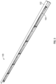
- FIG. 1 is an elevation view of one of many examples of a truss according to the disclosure.
- FIG. 2 is an elevation view of the truss of FIG. 1 , shown in a collapsed position, according to the disclosure.
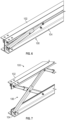
- FIG. 3 is a perspective view of another one of many examples of a truss according to the disclosure, shown in a collapsed position.
- FIG. 4 is a perspective view of the truss of FIG. 3 , shown in a partially expanded position, according to the disclosure.
- FIG. 5 is a perspective view of the truss of FIG. 3 , shown in a fully expanded position, according to the disclosure.
- FIG. 6 is a perspective view of still another one of many examples of a truss according to the disclosure, shown in a collapsed position.
- FIG. 7 is a perspective view of the truss of FIG. 6 , shown in an expanded position, according to the disclosure.
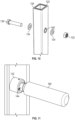
- FIG. 8 is a perspective view of one of many examples of a telescoping member, according to the disclosure.
- FIG. 9 is a perspective view of the telescoping member of FIG. 8 , shown in a locked position, according to the disclosure.
- FIG. 10 is a partially exploded view of the telescoping member of FIG. 9 according to the disclosure.
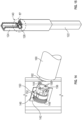
- FIG. 11 is a perspective view of the telescoping member of FIG. 10 , with inner and outer sections of the telescoping member shown partially transparent to show a concentric lock according to the disclosure.
- FIG. 12 is a perspective view of the concentric lock of FIG.
- FIG. 11 is a cut-away perspective view of one of many examples of a telescoping member, according to the disclosure.
- FIG. 16 is a cut-away perspective view of a portion of the telescoping member of Fig. 15 according to the disclosure.
- FIG. 17 is a cut-away perspective view of another portion of the telescoping member of Fig. 15 according to the disclosure.
- FIG. 18 is a front elevation view of one of many examples of a concentric lock, shown in a compressed position, according to the disclosure.
- FIG. 19 is a cut-away side elevation view of the concentric lock of FIG. 18 .
- FIG. 20 is a front elevation view of one of many examples of a concentric lock, shown in an extended position, according to the disclosure.
- FIG. 21 is a cut-away side elevation view of the concentric lock of FIG. 20 .
- FIG. 22 is a cut-away side elevation view of a portion of one of many examples of a telescoping member, showing a concentric lock in an extended position, according to the disclosure.
- FIG. 23 is a cut-away perspective view of a concentric lock according to the disclosure.
- FIG. 24 is a perspective view of one of many examples of a concentric lock according to the disclosure, shown in an extended position.
- FIG. 25 is a perspective view of one of many examples of a concentric lock according to the disclosure, shown in a compressed position.
- FIG. 26 is a perspective view of one of many examples of a concentric lock according to the disclosure, shown in a disengaged position.
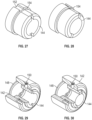
- FIG. 27 is a perspective view of one of many examples of a pin of the concentric lock of FIG. 25 according to the disclosure.
- FIG. 28 is a perspective view of one of many examples of a pin of the concentric lock of FIG. 26 shown in a disengaged position.
- FIG. 29 is a cut-away perspective view of the concentric lock of FIG. 25 according to the disclosure.
- FIG. 30 is a cut-away perspective view of the concentric lock of FIG. 26 shown in a disengaged position.
- FIG. 31 is a perspective view of one of many examples of a pin for a concentric lock according to the disclosure.
- FIG. 32 is a front elevation view of one of many examples of a pin for a concentric lock according to the disclosure.
- FIG. 33 is a perspective view of one of many examples of a key for a concentric lock according to the disclosure.
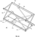
- FIG. 34 is a perspective view of one of many examples of an adjustable support system, shown in an expanded position, according to the disclosure.
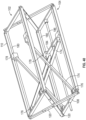
- FIG. 35 is a perspective view of one of many examples of an adjustable support system, shown in a partially expanded position, according to the disclosure.
- FIG. 36 is a perspective view of one of many examples of an adjustable support system, shown in a collapsed position, according to the disclosure.
- FIG. 37 is a cut-away perspective view of one of many examples of a telescoping member according to the disclosure.
- FIG. 38 is a perspective view of one of many examples of a telescoping member, showing different mounting positions, according to the disclosure.
- FIG. 39 is a perspective view of another one of many examples of an adjustable support system according to the disclosure.
- FIG. 40 is a perspective view of still another one of many examples of an adjustable support system according to the disclosure.
- FIGS. 1-40 are described in conjunction with one another.
- a collapsible support system 100 can include one or more support members, such as a first rigid support member 102 and a second rigid support member 104, and one or more locking mechanisms 106.
- the first rigid support member 102 can be disposed or positioned parallel to (i.e., at least substantially in parallel with) the second rigid support member 104.
- the first rigid support member 102 and/or the second rigid support member 104 can be or include a beam, and the system 100 can form a truss.
- first rigid support member 102 and/or the second rigid support member 104 can be a truss, frame, or box structure, and the system 100 can form a stand, platform, or other support structure providing support in three dimensions.
- the locking mechanism 106 can be configured to permit movement of the first rigid support member 102 with respect to the second rigid support member 104 (or vice versa) between or among a first position, a second position, a third position, and/or another position(s), which can be or include any position or number of positions according to an implementation of the disclosure.
- the system 100 can have a fully collapsed position, a fully expanded position, and one or more intermediate positions, and the various components of the system 100 can have corresponding positions accordingly.
- the system 100 can be selectively adjusted and fixed in one or more dimensions, such as height, width and/or length.
- a collapsible support system 100 such as the trusses illustrated in FIGS. 1-7 for exemplary purposes, can be stored and/or transported in a fully collapsed position or configuration, which can save space and increase efficiency during storage and transportation.
- the truss can be selectively expanded into any desired position of a number of available positions among or between the fully collapsed position and a fully expanded position.
- the truss can be utilized in a variety of situations and can accommodate various and/or variable on-site conditions or requirements, thereby simplifying logistical, design, and engineering considerations.
- the first rigid support member 102 can be adjacent to the second rigid support member 104 in a first (or other) position, as illustrated by, e.g., the nonlimiting examples of FIG. 2 , FIG. 3 , and FIG. 6 .
- the first rigid support member 102 can be spaced apart from the second rigid support member 104 in a second (or other) position, as illustrated by, e.g., the nonlimiting examples of FIG. 1 , FIG. 5 , and FIG. 7 .
- FIG. 34 , FIG. 35 , and FIG. 36 provide nonlimiting examples of a first position, a second position, and a third position, respectively.
- FIGS. 34-40 collectively illustrate how at least one example of the system 100 according to the disclosure can selectively accommodate and move among numerous different distinct positions in one or more directions.
- the first rigid support member 102 can be spaced farther from the second rigid support member 104 in the second position and/or third position than in the first position.
- the first rigid support member 102 can be spaced farther from the second rigid support member 104 in the third position than in the second position.
- the locking mechanism 106 can be configured to selectively lock the first and second rigid support members 102, 104 in any of numerous different positions, as required or desired in accordance with an implementation of the disclosure.
- the locking mechanism 106 can include one or more locking telescoping members 120, such as a first locking telescoping member 120a and a second locking telescoping member 120b.
- the first locking telescoping member 120a can be orthogonal to (i.e., at least substantially perpendicular to) the second locking telescoping member 120b in the second position.
- the first locking telescoping member 120a can be angularly fixed with respect to the second locking telescoping member 120b, with the first and second rigid support members 102, 104 locked in the second position.
- the first locking telescoping member 120a can be angularly fixed at or about 90 degrees (i.e., at least about 90 degrees) with respect to the second locking telescoping member 120b, with the first and second rigid support members 102, 104 locked in the second position. In at least one example, the first locking telescoping member 120a can be angularly fixed at or about 75 degrees with respect to the second locking telescoping member 120b, with the first and second rigid support members 102, 104 locked in the second position.
- the first locking telescoping member 120a can be angularly fixed at or about 60 degrees with respect to the second locking telescoping member 120b, with the first and second rigid support members 102, 104 locked in the second position. In at least one example, the first locking telescoping member 120a can be angularly fixed at or about 45 degrees with respect to the second locking telescoping member 120b, with the first and second rigid support members 102, 104 locked in the second position. In at least one example, the first locking telescoping member 120a can be angularly fixed at between 45 and 90 degrees (inclusive) with respect to the second locking telescoping member 120b, with the first and second rigid support members 102, 104 locked in the second position.
- any or each locking telescoping member(s) 120 can include an inner section 122, an outer section 124, and/or a concentric lock 140.
- the inner section 122 can be slideably mounted at least partially within the outer section 124.
- the inner section 122 telescopes within the outer section 124.
- any or each locking telescoping member(s) 120 can be a first length with the first and second rigid support members 102, 104 in the first position.
- any or each locking telescoping member(s) 120 can be a second length, longer than the first length, with the first and second rigid support members 102, 104 locked in the second position.
- any or each locking telescoping member(s) 120 can be a third length, longer than the second length, with the first and second rigid support members 102, 104 locked in a third position.
- the first locking telescoping member 120a and/or the second locking telescoping member 120b can include a concentric lock 140.
- any or each concentric lock 140 can include an outer housing 142 fixedly mounted to an inner section 122 of the corresponding locking telescoping member 120 and an inner pin 144 slideably mounted within the outer housing 142.
- the inner pin 144 can be biased towards an extended position in which the inner pin 144 extends from the outer housing 142 and engages a hole 126 in an outer section 124 of the corresponding locking telescoping member 120, thereby locking the corresponding locking telescoping member 120 and preventing further telescoping thereof.
- the inner pin 144 can be biased towards the extended position by a spring 146, which can be held within the outer housing 142 by a retaining ring 148. In at least one example, the inner pin 144 can slide longitudinally within the outer housing 142.
- a protrusion 150 such as a set screw, can extend inwardly from the outer housing 142. In at least one example, the protrusion 150 can ride within a groove 152 in the inner pin 144 as the inner pin 144 slides longitudinally within the outer housing 142.
- the inner pin 144 can be pushed into the outer housing 142 and rotated with respect thereto, such as by using a key 160, thereby locking the inner pin 144 at least partially within the outer housing 142 and permitting the corresponding locking telescoping member 120 to telescope freely.
- the inner pin 144 can include a periphery ledge 154.
- groove 152 of the inner pin 144 can extend into the periphery ledge 154.
- the inner pin 144 can be pushed into the outer housing 142 such that the groove 152 slides along the set screw 150, until the set screw 150 extends beyond the ledge 154.
- the inner pin 144 can be rotated with respect to the outer housing 142, such that the set screw 150 engages the ledge 154.
- the set screw 150 engaging the ledge 154 retains the inner pin 144 in a disengaged position, thereby permitting the locking telescoping member 120 to telescope freely.
- the inner pin 144 can receive a bolt 130 therethrough.
- the bolt 130 can be secured with a nut 132 and/or a number of washers 134.
- the bolt 130 can ensure concentric lock 140 locks the inner section 122 with respect to the outer section 124, thereby locking the locking telescoping member 120 and preventing further telescoping thereof.
- the bolt 130 can reinforce the concentric lock 140, preventing the concentric lock 140 from disengaging or otherwise failing to lock the inner section 122 with respect to the outer section 124, thereby locking the locking telescoping member 120.
- the outer housing 142 can be secured to the inner section 122 using one or more fasteners 156.
- the inner pin 144 can include one or more slots 158.
- the key 160 can include one or more blades 162 to engage the slots 158 in the inner pin 144, and by that engagement rotate the inner pin 144 as described therein.
- the locking mechanism 106 can include a first locking telescoping member 120a and a second locking telescoping member 120b adjacent to a first end of the first and second rigid support members 102, 104. In at least one example, the locking mechanism 106 can include a third locking telescoping member 120c and a fourth locking telescoping member 120d adjacent to a second end of the first and second rigid support members 102, 104. In at least one example, in the second position, the first locking telescoping member 120a can be orthogonal to the second locking telescoping member 120b and/or the third locking telescoping member 120c can be orthogonal to the fourth locking telescoping member 120d.
- any or each of the locking telescoping members 120 can include a concentric lock 140.
- each concentric lock 140 can include an outer housing 142 fixedly mounted to an inner section 122 of the corresponding locking telescoping member 120 and an inner pin 144 slideably mounted within the outer housing 142.
- the inner pin 144 can be biased towards an extended position in which the inner pin 144 extends from the outer housing 142 and engages a hole 126 in an outer section 124 of the corresponding locking telescoping member 120, thereby locking the corresponding locking telescoping member 120 and preventing further telescoping thereof.
- each inner pin 144 can be pushed into the corresponding outer housing 142 and rotated with respect thereto, thereby locking the inner pin 144 at least partially within the corresponding outer housing 142 and permitting the corresponding locking telescoping member 120 to telescope freely.
- the inner pin 144 of the first locking telescoping member 120a and the inner pin 144 of the second locking telescoping member 120b can receive a bolt 130 therethrough, thereby locking the first and second rigid support members 102, 104 in the second position and/or rigidly fixing the first locking telescoping member 120a with respect to the second locking telescoping member 120b.
- the locking mechanism includes a plurality of crossing pairs of locking telescoping members 120.
- each crossing pair of the locking telescoping members 120 can receive a bolt 130 therethrough when the first and second rigid support members 102, 104 are in the second position, thereby locking the first and second rigid support members 102, 104 in the second position and/or rigidly fixing each crossing pair of the locking telescoping members 120.
- one or more crossing pair of the locking telescoping members 120 can include one or more concentric locks 140.
- each crossing pair of the locking telescoping members 120 can include one or more concentric locks 140.
- the locking mechanism 106 can include an adjustment system 170 (e.g., one or more screw jacks, one or more scissor jacks, one or more hydraulic jacks, one or more rack and pinion mechanisms, one or more other jack or adjustment mechanisms, or any combination thereof), for adjusting and/or setting a distance between the first rigid support member 102 and the second rigid support member 104 and/or a position of one or more of the locking telescoping members 120.
- an adjustment system 170 e.g., one or more screw jacks, one or more scissor jacks, one or more hydraulic jacks, one or more rack and pinion mechanisms, one or more other jack or adjustment mechanisms, or any combination thereof
- the adjustment system 170 can adjust the distance between the first rigid support member 102 and the second rigid support member 104 and/or the position of one or more crossing pairs of locking telescoping members 120 in a smooth, continuous manner, such that any relative spacing between the first rigid support member 102 and the second rigid support member 104 can be achieved (i.e., any desired position of a number of optional positions among or between a fully collapsed position and a fully expanded position).
- each crossing pair of the locking telescoping members 120 can receive a bolt 130 or other fastener or boss therein or therethrough when the first and second rigid support members 102, 104 are in the first position, the second position, the third position, or any other chosen position, thereby locking the first and second rigid support members 102, 104 in the chosen position and/or rigidly fixing into position each crossing pair of the locking telescoping members 120.
- a single support system 100 can be used in a variety of applications, thereby simplifying logistics and reducing costs.
- an example of system 100 that can accommodate multiple different dimensional implementations can provide for universal use among two or more physical applications calling for different system heights, widths and/or lengths, which can reduce inventory requirements (i.e., versus stocking numerous different models or sizes of the system 100).
- the first and second rigid support members 102, 104 can be or include a beam, tube, truss, box, and/or frame.
- one or both of the first and second rigid support members 102, 104 can be or include a quadrilateral structure with two end members 108 coupled to two lateral members 110.
- the first and second rigid support members 102, 104 can be rectangular as illustrated in the exemplary figures mentioned above, that need not be the case, and the first and second rigid support members 102, 104 can be any shape required or desired in accordance with an implementation of the disclosure.
- each of the end members 108 and lateral members 110 can have any cross-sectional size and shape required or desired in accordance with an implementation of the disclosure, such as L-channel, C-channel, square tubing, rectangular tubing, or otherwise, whether separately or in combination, in whole or in part.
- the adjustment system 170 can include a plurality of actuation and/or support components for adjusting, setting and/or supporting a selected positioning of the first and second rigid support members 102, 104.
- adjustment system 170 can include one or more cross members 174 for supporting positioning of the first and second rigid support members 102, 104 relative to one another, such as a first pair of cross members 174 coupled to the first and second rigid support members 102, 104 and a second pair of cross members 174 coupled to the first and second rigid support members 102, 104.
- each cross member 174 can have a first end rotateably coupled to a fixed support 176 on one of the first and second rigid support members 102, 104 and a second end rotateably and/or slideably coupled to one of the first and second rigid support members 102, 104. In this manner, movement of the cross members 174 can cause or result in corresponding movement of the first and second rigid support members 102, 104 and the locking telescoping members 120.
- adjustment system 170 can include one or more sliding supports 178 slideably coupled to a corresponding one of the first and second rigid support members 102, 104 for supporting movement of the first and second rigid support members 102, 104 relative to one another.
- each cross member can be rotatably coupled to a sliding support 178, and each sliding support 178 can be slideably coupled to one or more corresponding guide members 180 coupled to one of the first and second rigid support members 102, 104.
- the adjustment system 170 can include one or more actuation components for selectively moving the cross members 174 to thereby selectively position the first and second rigid support members 102, 104 and the locking telescoping members 120.
- the adjustment system 170 can include one or more actuator members 184, such as a brace or other structural component, for supporting movement of one or more sliding supports 178, and one or more actuator drivers 186, such as a rod or other linkage or drive structure, for cooperating with and moving the one or more actuator members 184.
- the actuator member 184 can be coupled to a corresponding pair of sliding supports 178, such that the actuator member 184 and the corresponding sliding supports 178 move collectively or in unison, and the actuator driver 186 can be configured to slide or otherwise move the actuator member 184 and the corresponding sliding supports 178 relative to the first and second rigid support members 102, 104, such as longitudinally along a pair of guide members 180. As shown in FIGS.
- the actuator driver 186 can be or include a feedscrew rotateably coupled to a corresponding one of the first and second rigid support members 102, 104 and threadably coupled to a mating opening of actuator member 184, such that rotation of the feedscrew causes linear movement of the actuator member 184 and the corresponding sliding supports 178 relative to the first and second rigid support members 102, 104, and thus causes corresponding expanding or collapsing movement of the system 100 (i.e., depending on the direction of rotation of the feedscrew).
- this is but one example of many, and other actuation mechanisms are possible, such as via the implementation of linear actuators, chain drives, belt drives, gear drives and/or other types of actuation mechanisms capable of selectively adjusting the positioning of system 100 according to the disclosure.
- the adjustment system 170 can be manual or manually operated.
- the actuator driver 186 can be arranged for manual manipulation by a user or installer, such as by way of a ratchet, breakover bar, drill and/or other hand tools for operating the actuator driver 186 in accordance with an implementation at hand (e.g., rotating the actuator driver 186 in an implementation having a feedscrew).
- the adjustment system 170 can be wholly or partially automated and/or motorized, and can include an actuator 172.
- the actuator 172 can be or include any type of prime mover and/or associated linkage for controlling movement of one or more components of the adjustment system 170, as required or desired for an implementation of the disclosure.
- the actuator 172 can be or include a motor operably coupled to the actuator driver 186.
- the actuator 172 can be used to change or adjust the distance between or relative positioning of the first and second rigid support members 102, 104.
- the actuator 172 can be removably coupled to the actuator driver 186 and/or one or more other components of the system 100, such that, once a given implementation of the disclosure is put in place and adjusted accordingly, the actuator 172 can be removed and, for instance, utilized with another implementation of support system 100.
- the actuator 172 can remain coupled to the remainder of the system 100 during use of the system 100, e.g., in implementations of the system 100 where adjustment or repositioning of the first and second rigid support members 102, 104 may be desired periodically or otherwise from time to time.
- the locking mechanism 106 can include one or more crossing pairs of locking telescoping members 120. In at least one example, the locking mechanism 106 can include one or more angularly mounted locking telescoping members 120. In at least one example, the locking mechanism 106 can include one or more horizontally mounted locking telescoping members 120. In at least one example, the locking mechanism 106 can include one or more vertically mounted locking telescoping members 120. In at least one example, the locking mechanism 106 can include one or more locking telescoping members 120 having a concentric lock 140 and/or bolt 130 to secure the first and second rigid support members 102, 104 in any chosen available position and/or rigidly fix the locking telescoping members 120.
- each locking telescoping member 120 can include a concentric lock 140.
- each concentric lock 140 can include an outer housing 142 fixedly mounted to an inner section 122 of the corresponding locking telescoping member 120 and an inner pin 144 slideably mounted within the outer housing 142.
- the inner pin 144 can be biased towards an extended position in which the inner pin 144 extends from the outer housing 142 and engages a hole 126 in an outer section 124 of the corresponding locking telescoping member 120, thereby locking the corresponding locking telescoping member 120 and preventing further telescoping thereof.
- each inner pin 144 can be pushed into the corresponding outer housing 142 and rotated with respect thereto, thereby locking the inner pin 144 at least partially within the corresponding outer housing 142 and permitting the corresponding locking telescoping member 120 to telescope freely.
- a second crossing pair of locking telescoping members 120 can include a third locking telescoping member 120c and a fourth locking telescoping member 120d.
- the inner pin 144 of the third locking telescoping member 120c and the inner pin 144 of the fourth locking telescoping member 120d can align and/or receive another bolt 130 therethrough, such as when the first and second rigid support members 102, 104 are in the second position, thereby locking the first and second rigid support members 102, 104 in the second position and/or rigidly fixing the third locking telescoping member 120c with respect to the fourth locking telescoping member 120d.
- the locking mechanism 106 can be configured to lock the first and second rigid support members 102, 104 in the first position and/or multiple positions.
- the locking mechanism 106 can be configured to lock the first and second rigid support members 102, 104 in a third position, in which the first rigid support member 102 can be spaced farther from the second rigid support member 104 than in the second position.
- a collapsible support system can include a first rigid support member, a second rigid support member, which can be parallel to the first rigid support member, and a locking mechanism.
- the first rigid support member can be a first beam and/or the second rigid support member can be a second beam.
- the first rigid support member can be a first truss and/or the second rigid support member can be a second truss.
- the locking mechanism can be configured to permit movement of the first rigid support member with respect to the second rigid support member between a first position and a second position. In at least one example, the first rigid support member can be spaced farther from the second rigid support member in the second position than in the first position.
- the locking mechanism can also be configured to lock the first and second rigid support members in the second position. In at least one example, the locking mechanism can lock the first and second rigid support members in one or more other positions, such as one or more positions between the first position and the second position. In at least one example, the locking mechanism can lock the first and second rigid support members in any of a range of distinct available positions between the first position and the second position.
- the locking mechanism can include a first locking telescoping member and a second locking telescoping member.
- the first locking telescoping member can be orthogonal to the second locking telescoping member in the second position.
- the first locking telescoping member can include a first concentric lock.
- the second locking telescoping member can include a second concentric lock.
- either or both concentric lock(s) can include an outer housing fixedly mounted to an inner section of the corresponding locking telescoping member and an inner pin slideably mounted within the outer housing.
- the inner pin can be biased towards an extended position in which the inner pin extends from the outer housing and engages a hole in an outer section of the corresponding locking telescoping member, thereby locking the corresponding locking telescoping member and preventing further telescoping thereof.
- the inner pin can be pushed into the outer housing and rotated with respect thereto, thereby locking the inner pin within the outer housing and permitting the corresponding locking telescoping member to telescope freely.
- the inner pin can receive a bolt therethrough.
- the locking mechanism can include a first locking telescoping member and a second locking telescoping member adjacent to a first end of the first and second rigid support members. In at least one example, the locking mechanism can include a third locking telescoping member and a fourth locking telescoping member adjacent to a second end of the first and second rigid support members. In at least one example, in the second position, the first locking telescoping member can be orthogonal to the second locking telescoping member and/or the third locking telescoping member can be orthogonal to the fourth locking telescoping member.
- any or each of the locking telescoping members can include a concentric lock.
- each concentric lock can include an outer housing fixedly mounted to an inner section of the corresponding locking telescoping member and an inner pin slideably mounted within the outer housing.
- the inner pin can be biased towards an extended position in which the inner pin extends from the outer housing and engages a hole in an outer section of the corresponding locking telescoping member, thereby locking the corresponding locking telescoping member and preventing further telescoping thereof.
- each inner pin can be pushed into the corresponding outer housing and rotated with respect thereto, thereby locking the inner pin within the corresponding outer housing and permitting the corresponding locking telescoping member to telescope freely.
- the inner pin of the first locking telescoping member and the inner pin of the second locking telescoping member can receive a first bolt therethrough, thereby locking the first and second rigid support members in the second position and/or rigidly fixing the first locking telescoping member with respect to the second locking telescoping member.
- the locking mechanism includes a plurality of crossing pairs of locking telescoping members. In at least one example, each crossing pair of the locking telescoping members can receive a bolt therethrough when the first and second rigid support members are in the second position, thereby locking the first and second rigid support members in the second position and/or rigidly fixing each crossing pair of the locking telescoping members.
- the locking mechanism can include an adjustment system, such as one or more screw jacks, one or more scissor jacks, one or more hydraulic jacks, one or more rack and pinion mechanisms, one or more other jack or adjustment mechanisms, or any combination thereof, configured to adjust a distance between the first rigid support member and the second rigid support member and/or one or more crossing pairs of locking telescoping members.
- each crossing pair of the locking telescoping members can receive a bolt therethrough when the first and second rigid support members are in the second position, thereby locking the first and second rigid support members in the second position and/or rigidly fixing each crossing pair of the locking telescoping members.
- each locking telescoping member can include a concentric lock.
- each concentric lock can include an outer housing fixedly mounted to an inner section of the corresponding locking telescoping member and an inner pin slideably mounted within the outer housing.
- the inner pin can be biased towards an extended position in which the inner pin extends from the outer housing and engages a hole in an outer section of the corresponding locking telescoping member, thereby locking the corresponding locking telescoping member and preventing further telescoping thereof.
- each inner pin can be pushed into the corresponding outer housing and rotated with respect thereto, thereby locking the inner pin within the corresponding outer housing and permitting the corresponding locking telescoping member to telescope freely.
- a first crossing pair of locking telescoping members can include a first locking telescoping member and a second locking telescoping member.
- the inner pin of the first locking telescoping member and the inner pin of the second locking telescoping member can align and/or receive a first bolt therethrough, such as when the first and second rigid support members are in the second position, thereby locking the first and second rigid support members in the second position and/or rigidly fixing the first locking telescoping member with respect to the second locking telescoping member.
- the system can include a first pair of locking telescoping members coupled to first ends of the first and second rigid support members, and a second pair of locking telescoping members coupled to second ends of the first and second rigid support members.
- each of the locking telescoping members can be configured to be selectively locked at a plurality of different lengths, thereby selectively limiting a maximum distance between the first and second rigid support members.
- each of the locking telescoping members can be configured to be selectively locked at a plurality of different lengths, thereby allowing a user to choose among a plurality of different system dimensional arrangements, such as heights and widths.
- each of the locking telescoping members can include an end fixedly attached to the first rigid support member and another end fixedly attached to the second rigid support member.
- each of the locking telescoping members can include an end rotateably attached to the first rigid support member and another end rotateably attached to the second rigid support member.
- the first pair of locking telescoping members can be rotateably coupled to one another and the second pair of locking telescoping members can be rotateably coupled to one another, such as at positions between the first and second rigid support members.
- the locking mechanism and the first and second pairs of locking telescoping members can be collectively configured to enable selective adjustment and locking of the system among a plurality of different dimensional combinations, which can include heights, widths, and/or lengths.
- the locking mechanism which can include one or more pairs of locking telescoping members, or any portions thereof, can be collectively configured to enable selective adjustment and locking of the system among any of a plurality of different dimensional combinations, which can include heights, widths, and/or lengths.
- the locking mechanism and/or the pairs of locking telescoping members can be collectively configured to enable selective adjustment and locking of the system among any of a plurality of different configurations having varying distances between the first and second rigid support members.
- the system can include an adjustment system having one or more cross members for supporting positioning of the first and second rigid support members, such as a first pair of cross members coupled to the first and second rigid support members and a second pair of cross members coupled to the first and second rigid support members.
- each cross member can have an end rotateably coupled to a fixed support on one of the first and second rigid support members and another end rotateably and/or slideably coupled to one of the first and second rigid support members.
- movement of the cross members can cause or result in corresponding movement of one or more other system components, such as the first and second rigid support members and the locking telescoping members.
- the adjustment system can include one or more sliding supports slideably coupled to a corresponding one of the first and second rigid support members.
- one end of each cross member can be rotatably coupled to a sliding support, and each sliding support can be slideably coupled to one or more corresponding guide members coupled to one of the first and second rigid support members.
- one end of each of the cross members can be slideably coupled to one of the first and second rigid support members.
- the first pair of cross members can be rotateably coupled to one another and the second pair of cross members can be rotateably coupled to one another, such as at positions between the first and second rigid support members.
- the system can include a first pair of sliding supports slideably coupled to the first rigid support member, and a second pair of sliding supports slideably coupled to the second rigid support member.
- an end of each of the cross members can be rotateably coupled to corresponding ones of the sliding supports.
- the system can include a first pair of guide members coupled to the first rigid support member, and a second pair of guide members coupled to the second rigid support member. Respective ones of the first pair of sliding supports can be slideably coupled to corresponding ones of the first pair of guide members, and respective ones of the second pair of sliding supports can be slideably coupled to corresponding ones of the second pair of guide members.
- the system can include an actuator member coupled to a pair of sliding supports and configured to slide relative to a pair of guide members in unison with the sliding supports.
- an actuator driver can be configured to selectively move the actuator member for causing a change of position of at least one of the first and second rigid support members.
- the actuator driver can be a feedscrew, and the feedscrew can be rotateably coupled to one or more of the rigid support members and threadably coupled to the actuator member.
- the system can include an actuator coupled to the actuator driver and configured to selectively move the actuator driver for causing a change of position of the actuator member.
- the actuator can be or include a motor.
- the actuator can be removably coupled to one or more other system components.
- the devices, systems and methods can be implemented for numerous different types and sizes in numerous different industries.
- the various methods and examples of the devices, systems and methods can be included in combination with each other to produce variations of the disclosed methods and examples. Discussion of singular elements can include plural elements and vice versa.
- the order of steps can occur in a variety of sequences unless otherwise specifically limited.
- the various steps described herein can be combined with other steps, interlineated with the stated steps, and/or split into multiple steps.
- elements have been described functionally and can be embodied as separate components or can be combined into components having multiple functions.
Landscapes
- Engineering & Computer Science (AREA)
- General Engineering & Computer Science (AREA)
- Architecture (AREA)
- Mechanical Engineering (AREA)
- Physics & Mathematics (AREA)
- Electromagnetism (AREA)
- Civil Engineering (AREA)
- Structural Engineering (AREA)
- Accommodation For Nursing Or Treatment Tables (AREA)
- Mutual Connection Of Rods And Tubes (AREA)
Abstract
Description
- This application claims the benefit of
Indian Provisional Patent Application No. 202321056657 filed August 24, 2023 - The present disclosure relates generally to support structures and more specifically relates to support structures for data centers.
- Datacenters often have differing site conditions. As such, different mounting heights may be required for different sites. This can require stocking a large variety of different stands, or other support structures, such as trusses. Trusses, used in data centers for example, can be bulky and can require significant storage and transportation space. For this reason, such trusses are often stored and/or transported disassembled. However, this only increases the labor required for installation, once on site, as the trusses then need to be assembled during installation.
- Applicant has created new and useful devices, systems and methods for collapsible support systems. A collapsible support system according to the disclosure can be stored and/or transported in a fully collapsed position or configuration, which can save space and increase efficiency during storage and transportation. Once on site, the system can be selectively expanded into any desired position of a number of available positions among or between the fully collapsed position and a fully expanded position. In this manner, a single system can be utilized in a variety of situations and can accommodate various and/or variable on-site conditions or requirements, thereby simplifying logistical, design, and engineering considerations.
- In at least one example, a support system according to the disclosure, such as a collapsible or adjustable support system, can include a plurality of rigid support members, a plurality of telescoping support members, and one or more locking mechanisms for selectively fixing the system in one or more positions or configurations, such as in a plurality of dimensions. In at least one example, a collapsible support system can include a first rigid support member, a second rigid support member, which can be parallel to the first rigid support member, and a locking mechanism. In at least one example, the first rigid support member can be a first beam and/or the second rigid support member can be a second beam. In at least one example, the first rigid support member can be a first truss and/or the second rigid support member can be a second truss.
- In at least one example, the locking mechanism can be configured to permit movement of the first rigid support member with respect to the second rigid support member between a first position and a second position. In at least one example, the first rigid support member can be spaced farther from the second rigid support member in the second position than in the first position. In at least one example, the locking mechanism can also be configured to lock the first and second rigid support members in the second position. In at least one example, the locking mechanism can lock the first and second rigid support members in one or more other positions, such as one or more positions between the first position and the second position. In at least one example, the locking mechanism can lock the first and second rigid support members in any position between the first position and the second position.
- In at least one example, the locking mechanism can include a first locking telescoping member and a second locking telescoping member. In at least one example, the first locking telescoping member can be orthogonal to the second locking telescoping member in the second position.
- In at least one example, the first locking telescoping member can include a first concentric lock. In at least one example, the second locking telescoping member can include a second concentric lock. In at least one example, either or both concentric lock(s) can include an outer housing fixedly mounted to an inner section of the corresponding locking telescoping member and an inner pin slideably mounted within the outer housing. In at least one example, the inner pin can be biased towards an extended position in which the inner pin extends from the outer housing and engages a hole in an outer section of the corresponding locking telescoping member, thereby locking the corresponding locking telescoping member and preventing further telescoping thereof. In at least one example, the inner pin can be pushed into the outer housing and rotated with respect thereto, thereby locking the inner pin within the outer housing and permitting the corresponding locking telescoping member to telescope freely. In at least one example, the inner pin can receive a bolt therethrough.
- In at least one example, the locking mechanism can include a first locking telescoping member and a second locking telescoping member adjacent to a first end of the first and second rigid support members. In at least one example, the locking mechanism can include a third locking telescoping member and a fourth locking telescoping member adjacent to a second end of the first and second rigid support members. In at least one example, in the second position, the first locking telescoping member can be orthogonal to the second locking telescoping member and/or the third locking telescoping member can be orthogonal to the fourth locking telescoping member.
- In at least one example, any or each of the locking telescoping members can include a concentric lock. In at least one example, each concentric lock can include an outer housing fixedly mounted to an inner section of the corresponding locking telescoping member and an inner pin slideably mounted within the outer housing. In at least one example, the inner pin can be biased towards an extended position in which the inner pin extends from the outer housing and engages a hole in an outer section of the corresponding locking telescoping member, thereby locking the corresponding locking telescoping member and preventing further telescoping thereof. In at least one example, each inner pin can be pushed into the corresponding outer housing and rotated with respect thereto, thereby locking the inner pin within the corresponding outer housing and permitting the corresponding locking telescoping member to telescope freely.
- In at least one example, the inner pin of the first locking telescoping member and the inner pin of the second locking telescoping member can receive a first bolt therethrough, thereby locking the first and second rigid support members in the second position and/or rigidly fixing the first locking telescoping member with respect to the second locking telescoping member. In at least one example, the locking mechanism includes a plurality of crossing pairs of locking telescoping members. In at least one example, each crossing pair of the locking telescoping members can receive a bolt therethrough when the first and second rigid support members are in the second position, thereby locking the first and second rigid support members in the second position and/or rigidly fixing each crossing pair of the locking telescoping members.
- In at least one example, the locking mechanism can include an adjustment system, such as one or more screw jacks, one or more scissor jacks, one or more hydraulic jacks, one or more rack and pinion mechanisms, one or more other jack or adjustment mechanisms, or any combination thereof, configured to adjust a distance between the first rigid support member and the second rigid support member and/or one or more crossing pairs of locking telescoping members. In at least one example, each crossing pair of the locking telescoping members can receive a bolt therethrough when the first and second rigid support members are in the second position, thereby locking the first and second rigid support members in the second position and/or rigidly fixing each crossing pair of the locking telescoping members.
- In at least one example, each locking telescoping member can include a concentric lock. In at least one example, each concentric lock can include an outer housing fixedly mounted to an inner section of the corresponding locking telescoping member and an inner pin slideably mounted within the outer housing. In at least one example, the inner pin can be biased towards an extended position in which the inner pin extends from the outer housing and engages a hole in an outer section of the corresponding locking telescoping member, thereby locking the corresponding locking telescoping member and preventing further telescoping thereof. In at least one example, each inner pin can be pushed into the corresponding outer housing and rotated with respect thereto, thereby locking the inner pin within the corresponding outer housing and permitting the corresponding locking telescoping member to telescope freely.
- In at least one example, a first crossing pair of locking telescoping members can include a first locking telescoping member and a second locking telescoping member. In at least one example, the inner pin of the first locking telescoping member and the inner pin of the second locking telescoping member can align and/or receive a first bolt therethrough, such as when the first and second rigid support members are in the second position, thereby locking the first and second rigid support members in the second position and/or rigidly fixing the first locking telescoping member with respect to the second locking telescoping member.
- In at least one example, the locking mechanism can be configured to lock the first and second rigid support members in the first position and/or multiple positions. For example, in at least one example, the locking mechanism can be configured to lock the first and second rigid support members in a third position, in which the first rigid support member can be spaced farther from the second rigid support member than in the second position.
- In at least one example, the system can include a first pair of locking telescoping members coupled to first ends of the first and second rigid support members, and a second pair of locking telescoping members coupled to second ends of the first and second rigid support members. In at least one example, each of the locking telescoping members can be configured to be selectively locked at a plurality of different lengths, thereby selectively limiting a maximum distance between the first and second rigid support members. In at least one example, each of the locking telescoping members can be configured to be selectively locked at a plurality of different lengths, thereby allowing a user to choose among a plurality of different system dimensional arrangements, such as heights and widths. In at least one example, each of the locking telescoping members can include an end fixedly attached to the first rigid support member and another end fixedly attached to the second rigid support member. In at least one example, each of the locking telescoping members can include an end rotateably attached to the first rigid support member and another end rotateably attached to the second rigid support member. In at least one example, the first pair of locking telescoping members can be rotateably coupled to one another and the second pair of locking telescoping members can be rotateably coupled to one another, such as at positions between the first and second rigid support members. In at least one example, the locking mechanism and the first and second pairs of locking telescoping members can be collectively configured to enable selective adjustment and locking of the system among a plurality of different dimensional combinations, which can include heights, widths and/or lengths. In at least one example, the locking mechanism, which can include one or more pairs of locking telescoping members, or any portions thereof, can be collectively configured to enable selective adjustment and locking of the system among any of a plurality of different dimensional combinations, which can include heights, widths, and/or lengths. In at least one example, the locking mechanism and/or the pairs of locking telescoping members can be collectively configured to enable selective adjustment and locking of the system among any of a plurality of different configurations having varying distances between the first and second rigid support members.
- In at least one example, the system can include an adjustment system having one or more cross members for supporting positioning of the first and second rigid support members, such as a first pair of cross members coupled to the first and second rigid support members and a second pair of cross members coupled to the first and second rigid support members. In at least one example, each cross member can have an end rotateably coupled to a fixed support on one of the first and second rigid support members and another end rotateably and/or slideably coupled to one of the first and second rigid support members. In at least one example, movement of the cross members can cause or result in corresponding movement of one or more other system components, such as the first and second rigid support members and the locking telescoping members.
- In at least one example, the adjustment system can include one or more sliding supports slideably coupled to a corresponding one of the first and second rigid support members. In at least one example, one end of each cross member can be rotatably coupled to a sliding support, and each sliding support can be slideably coupled to one or more corresponding guide members coupled to one of the first and second rigid support members. In at least one example, one end of each of the cross members can be slideably coupled to one of the first and second rigid support members. In at least one example, the first pair of cross members can be rotateably coupled to one another and the second pair of cross members can be rotateably coupled to one another, such as at positions between the first and second rigid support members.
- In at least one example, the system can include a first pair of sliding supports slideably coupled to the first rigid support member, and a second pair of sliding supports slideably coupled to the second rigid support member. In at least one example, an end of each of the cross members can be rotateably coupled to corresponding ones of the sliding supports. In at least one example, the system can include a first pair of guide members coupled to the first rigid support member, and a second pair of guide members coupled to the second rigid support member. Respective ones of the first pair of sliding supports can be slideably coupled to corresponding ones of the first pair of guide members, and respective ones of the second pair of sliding supports can be slideably coupled to corresponding ones of the second pair of guide members.
- In at least one example, the system can include an actuator member coupled to a pair of sliding supports and configured to be driven relative to a pair of guide members in unison with the sliding supports. In at least one example, an actuator driver can be configured to selectively move the actuator member for causing a change of position of at least one of the first and second rigid support members. In at least one example, the actuator driver can be a feedscrew, and the feedscrew can be rotateably coupled to one or more of the rigid support members and threadably coupled to the actuator member. In at least one example, the system can include an actuator coupled to the actuator driver and configured to selectively move the actuator driver for causing a change of position of the actuator member. In at least one example, the actuator can be or can include a motor. In at least one example, the actuator can be removably coupled to one or more other system components. In at least one example, the actuator can be manually driven (e.g., crank, wrench, etc.).
-
-
FIG. 1 is an elevation view of one of many examples of a truss according to the disclosure. -
FIG. 2 is an elevation view of the truss ofFIG. 1 , shown in a collapsed position, according to the disclosure. -
FIG. 3 is a perspective view of another one of many examples of a truss according to the disclosure, shown in a collapsed position. -
FIG. 4 is a perspective view of the truss ofFIG. 3 , shown in a partially expanded position, according to the disclosure. -
FIG. 5 is a perspective view of the truss ofFIG. 3 , shown in a fully expanded position, according to the disclosure. -
FIG. 6 is a perspective view of still another one of many examples of a truss according to the disclosure, shown in a collapsed position. -
FIG. 7 is a perspective view of the truss ofFIG. 6 , shown in an expanded position, according to the disclosure. -
FIG. 8 is a perspective view of one of many examples of a telescoping member, according to the disclosure. -
FIG. 9 is a perspective view of the telescoping member ofFIG. 8 , shown in a locked position, according to the disclosure. -
FIG. 10 is a partially exploded view of the telescoping member ofFIG. 9 according to the disclosure. -
FIG. 11 is a perspective view of the telescoping member ofFIG. 10 , with inner and outer sections of the telescoping member shown partially transparent to show a concentric lock according to the disclosure. -
FIG. 12 is a perspective view of the concentric lock ofFIG. 11 , shown in an extended position, according to the disclosure. -
FIG. 13 is a perspective view of the concentric lock ofFIG. 11 , shown in a compressed position, according to the disclosure. -
FIG. 14 is a perspective view of the concentric lock ofFIG. 11 , shown in a disengaged position, according to the disclosure. -
FIG. 15 is a cut-away perspective view of one of many examples of a telescoping member, according to the disclosure. -
FIG. 16 is a cut-away perspective view of a portion of the telescoping member ofFig. 15 according to the disclosure. -
FIG. 17 is a cut-away perspective view of another portion of the telescoping member ofFig. 15 according to the disclosure. -
FIG. 18 is a front elevation view of one of many examples of a concentric lock, shown in a compressed position, according to the disclosure. -
FIG. 19 is a cut-away side elevation view of the concentric lock ofFIG. 18 . -
FIG. 20 is a front elevation view of one of many examples of a concentric lock, shown in an extended position, according to the disclosure. -
FIG. 21 is a cut-away side elevation view of the concentric lock ofFIG. 20 . -
FIG. 22 is a cut-away side elevation view of a portion of one of many examples of a telescoping member, showing a concentric lock in an extended position, according to the disclosure. -
FIG. 23 is a cut-away perspective view of a concentric lock according to the disclosure. -
FIG. 24 is a perspective view of one of many examples of a concentric lock according to the disclosure, shown in an extended position. -
FIG. 25 is a perspective view of one of many examples of a concentric lock according to the disclosure, shown in a compressed position. -
FIG. 26 is a perspective view of one of many examples of a concentric lock according to the disclosure, shown in a disengaged position. -
FIG. 27 is a perspective view of one of many examples of a pin of the concentric lock ofFIG. 25 according to the disclosure. -
FIG. 28 is a perspective view of one of many examples of a pin of the concentric lock ofFIG. 26 shown in a disengaged position. -
FIG. 29 is a cut-away perspective view of the concentric lock ofFIG. 25 according to the disclosure. -
FIG. 30 is a cut-away perspective view of the concentric lock ofFIG. 26 shown in a disengaged position. -
FIG. 31 is a perspective view of one of many examples of a pin for a concentric lock according to the disclosure. -
FIG. 32 is a front elevation view of one of many examples of a pin for a concentric lock according to the disclosure. -
FIG. 33 is a perspective view of one of many examples of a key for a concentric lock according to the disclosure. -
FIG. 34 is a perspective view of one of many examples of an adjustable support system, shown in an expanded position, according to the disclosure. -
FIG. 35 is a perspective view of one of many examples of an adjustable support system, shown in a partially expanded position, according to the disclosure. -
FIG. 36 is a perspective view of one of many examples of an adjustable support system, shown in a collapsed position, according to the disclosure. -
FIG. 37 is a cut-away perspective view of one of many examples of a telescoping member according to the disclosure. -
FIG. 38 is a perspective view of one of many examples of a telescoping member, showing different mounting positions, according to the disclosure. -
FIG. 39 is a perspective view of another one of many examples of an adjustable support system according to the disclosure. -
FIG. 40 is a perspective view of still another one of many examples of an adjustable support system according to the disclosure. - The Figures described above and the written description of specific structures and functions below are not presented to limit the scope of what Applicant has invented or the scope of the appended claims. Rather, the Figures and written description are provided to teach any person skilled in the art to make and use of the patent protection is sought. Those skilled in the art will appreciate that not all features of a commercial example are described or shown for the sake of clarity and understanding. Persons of skill in this art will also appreciate that the development of an actual commercial example incorporating aspects will require numerous implementation-specific decisions to achieve the developer's ultimate goal for the commercial example. Such implementation-specific decisions may include, and likely are not limited to, compliance with system-related, business-related, government-related and other constraints, which may vary by specific implementation, location and from time to time. While a developer's efforts might be complex and time-consuming in an absolute sense, such efforts would be, nevertheless, a routine undertaking for those of skill in this art having benefit of this disclosure. It must be understood the examples disclosed and taught herein are susceptible to numerous and various modifications and alternative forms.
- The use of a singular term, such as, but not limited to, "a," is not intended as limiting of the number of items. Also, the use of relational terms, such as, but not limited to, "top," "bottom," "left," "right," "upper," "lower," "down," "up," "side," and the like are used in the written description for clarity in specific reference to the Figures and are not intended to limit the scope of the appended claims. The terms "including" and "such as" are illustrative and not limitative. The terms "couple," "coupled," "coupling," "coupler," and like terms are used broadly herein and can include any method or device for securing, binding, bonding, fastening, attaching, joining, inserting therein, forming thereon or therein, communicating, or otherwise associating, for example, mechanically, magnetically, electrically, chemically, operably, directly or indirectly with intermediate elements, one or more pieces of members together and can further include without limitation integrally forming one functional member with another in a unity fashion. The coupling can occur in any direction, including rotationally. Further, all parts and components of the disclosure that are capable of being physically embodied inherently include imaginary and real characteristics regardless of whether such characteristics are expressly described herein, including but not limited to characteristics such as axes, ends, inner and outer surfaces, interior spaces, tops, bottoms, sides, boundaries, dimensions (e.g., height, length, width, thickness), mass, weight, volume and density, among others.
- Any process flowcharts discussed herein illustrate the operation of possible implementations of systems, methods, and computer program products according to various examples of the present disclosure. In this regard, each block in a flowchart may represent a module, segment, or portion of code, which can include one or more executable instructions for implementing the specified logical function(s). It should also be noted that, in some implementations, the function(s) noted in the block(s) might occur out of the order depicted in the figures. For example, blocks shown in succession may, in fact, be executed substantially concurrently. It will also be noted that each block of flowchart illustration can be implemented by special purpose hardware-based systems that perform the specified functions or acts, or combinations of special purpose hardware and computer instructions.
- Applicant has created new and useful devices, systems and methods for collapsible support systems, such as for advantageously increasing the efficiency of installation thereof. In at least one example, a collapsible support system according to the disclosure can include a plurality of support members and one or more locking mechanisms. In at least one example, the locking mechanism(s) can selectively permit movement of one or more support members relative to one or more other support members, such as between or among two or more positions. In at least one example, one support member can be spaced or disposed farther from another support member in one position relative to another position. In at least one example, the locking mechanism(s) and a plurality of telescoping members can collectively provide for choosing among a plurality of different dimensional configurations and selectively locking the system into a chosen configuration.
- A collapsible support system according to the disclosure can be stored and/or transported in a fully collapsed position or configuration, which can save space and increase efficiency during storage and transportation. Once on site, the system can be selectively expanded into any desired position of a number of available positions among or between the fully collapsed position and a fully expanded position. In this manner, a single system can be utilized in a variety of situations and can accommodate various and/or variable on-site conditions or requirements, thereby simplifying logistical, design, and engineering considerations.
-
FIG. 1 is an elevation view of one of many examples of a truss according to the disclosure.FIG. 2 is an elevation view of the truss ofFIG. 1 , shown in a collapsed position, according to the disclosure.FIG. 3 is a perspective view of another one of many examples of a truss according to the disclosure, shown in a collapsed position.FIG. 4 is a perspective view of the truss ofFIG. 3 , shown in a partially expanded position, according to the disclosure.FIG. 5 is a perspective view of the truss ofFIG. 3 , shown in a fully expanded position, according to the disclosure.FIG. 6 is a perspective view of still another one of many examples of a truss according to the disclosure, shown in a collapsed position.FIG. 7 is a perspective view of the truss ofFIG. 6 , shown in an expanded position, according to the disclosure.FIG. 8 is a perspective view of one of many examples of a telescoping member, according to the disclosure.FIG. 9 is a perspective view of the telescoping member ofFIG. 8 , shown in a locked position, according to the disclosure.FIG. 10 is a partially exploded view of the telescoping member ofFIG. 9 according to the disclosure.FIG. 11 is a perspective view of the telescoping member ofFIG. 10 , with inner and outer sections of the telescoping member shown partially transparent to show a concentric lock according to the disclosure.FIG. 12 is a perspective view of the concentric lock ofFIG. 11 , shown in an extended position, according to the disclosure.FIG. 13 is a perspective view of the concentric lock ofFIG. 11 , shown in a compressed position, according to the disclosure.FIG. 14 is a perspective view of the concentric lock ofFIG. 11 , shown in a disengaged position, according to the disclosure.FIG. 15 is a cut-away perspective view of one of many examples of a telescoping member, according to the disclosure.FIG. 16 is a cut-away perspective view of a portion of the telescoping member ofFig. 15 according to the disclosure.FIG. 17 is a cut-away perspective view of another portion of the telescoping member ofFig. 15 according to the disclosure.FIG. 18 is a front elevation view of one of many examples of a concentric lock, shown in a compressed position, according to the disclosure.FIG. 19 is a cut-away side elevation view of the concentric lock ofFIG. 18 .FIG. 20 is a front elevation view of one of many examples of a concentric lock, shown in an extended position, according to the disclosure.FIG. 21 is a cut-away side elevation view of the concentric lock ofFIG. 20 .FIG. 22 is a cut-away side elevation view of a portion of one of many examples of a telescoping member, showing a concentric lock in an extended position, according to the disclosure.FIG. 23 is a cut-away perspective view of a concentric lock according to the disclosure.FIG. 24 is a perspective view of one of many examples of a concentric lock according to the disclosure, shown in an extended position.FIG. 25 is a perspective view of one of many examples of a concentric lock according to the disclosure, shown in a compressed position.FIG. 26 is a perspective view of one of many examples of a concentric lock according to the disclosure, shown in a disengaged position.FIG. 27 is a perspective view of one of many examples of a pin of the concentric lock ofFIG. 25 according to the disclosure.FIG. 28 is a perspective view of one of many examples of a pin of the concentric lock ofFIG. 26 shown in a disengaged position.FIG. 29 is a cut-away perspective view of the concentric lock ofFIG. 25 according to the disclosure.FIG. 30 is a cut-away perspective view of the concentric lock ofFIG. 26 shown in a disengaged position.FIG. 31 is a perspective view of one of many examples of a pin for a concentric lock according to the disclosure.FIG. 32 is a front elevation view of one of many examples of a pin for a concentric lock according to the disclosure.FIG. 33 is a perspective view of one of many examples of a key for a concentric lock according to the disclosure.FIG. 34 is a perspective view of one of many examples of an adjustable support system, shown in an expanded position, according to the disclosure.FIG. 35 is a perspective view of one of many examples of an adjustable support system, shown in a partially expanded position, according to the disclosure.FIG. 36 is a perspective view of one of many examples of an adjustable support system, shown in a collapsed position, according to the disclosure.FIG. 37 is a cut-away perspective view of one of many examples of a telescoping member according to the disclosure.FIG. 38 is a perspective view of one of many examples of a telescoping member, showing different mounting positions, according to the disclosure.FIG. 39 is a perspective view of another one of many examples of an adjustable support system according to the disclosure.FIG. 40 is a perspective view of still another one of many examples of an adjustable support system according to the disclosure.FIGS. 1-40 are described in conjunction with one another. - In at least one example, a
collapsible support system 100 can include one or more support members, such as a firstrigid support member 102 and a secondrigid support member 104, and one ormore locking mechanisms 106. In at least one example, the firstrigid support member 102 can be disposed or positioned parallel to (i.e., at least substantially in parallel with) the secondrigid support member 104. In at least one example, the firstrigid support member 102 and/or the secondrigid support member 104 can be or include a beam, and thesystem 100 can form a truss. In at least one example, one or both of the firstrigid support member 102 and/or the secondrigid support member 104 can be a truss, frame, or box structure, and thesystem 100 can form a stand, platform, or other support structure providing support in three dimensions. - In at least one example, the
locking mechanism 106 can be configured to permit movement of the firstrigid support member 102 with respect to the second rigid support member 104 (or vice versa) between or among a first position, a second position, a third position, and/or another position(s), which can be or include any position or number of positions according to an implementation of the disclosure. For example, in at least one example, thesystem 100 can have a fully collapsed position, a fully expanded position, and one or more intermediate positions, and the various components of thesystem 100 can have corresponding positions accordingly. As another example, in at least one example, thesystem 100 can be selectively adjusted and fixed in one or more dimensions, such as height, width and/or length. In this manner, acollapsible support system 100 according to the disclosure, such as the trusses illustrated inFIGS. 1-7 for exemplary purposes, can be stored and/or transported in a fully collapsed position or configuration, which can save space and increase efficiency during storage and transportation. Once on site, the truss can be selectively expanded into any desired position of a number of available positions among or between the fully collapsed position and a fully expanded position. Thus, the truss can be utilized in a variety of situations and can accommodate various and/or variable on-site conditions or requirements, thereby simplifying logistical, design, and engineering considerations. - In at least one example, the first
rigid support member 102 can be adjacent to the secondrigid support member 104 in a first (or other) position, as illustrated by, e.g., the nonlimiting examples ofFIG. 2 ,FIG. 3 , andFIG. 6 . In at least one example, the firstrigid support member 102 can be spaced apart from the secondrigid support member 104 in a second (or other) position, as illustrated by, e.g., the nonlimiting examples ofFIG. 1 ,FIG. 5 , andFIG. 7 . Similarly,FIG. 34 ,FIG. 35 , andFIG. 36 provide nonlimiting examples of a first position, a second position, and a third position, respectively. Other possible examples of a first position, a second position and/or other positions can be or include any position or series of distinct positions according to an implementation of the disclosure. For instance,FIGS. 34-40 collectively illustrate how at least one example of thesystem 100 according to the disclosure can selectively accommodate and move among numerous different distinct positions in one or more directions. In at least one example, the firstrigid support member 102 can be spaced farther from the secondrigid support member 104 in the second position and/or third position than in the first position. In at least one example, the firstrigid support member 102 can be spaced farther from the secondrigid support member 104 in the third position than in the second position. In at least one example, thelocking mechanism 106 can be configured to selectively lock the first and secondrigid support members - In at least one example, the
locking mechanism 106 can include one or morelocking telescoping members 120, such as a firstlocking telescoping member 120a and a secondlocking telescoping member 120b. In at least one example, the firstlocking telescoping member 120a can be orthogonal to (i.e., at least substantially perpendicular to) the secondlocking telescoping member 120b in the second position. In at least one example, the firstlocking telescoping member 120a can be angularly fixed with respect to the secondlocking telescoping member 120b, with the first and secondrigid support members locking telescoping member 120a can be angularly fixed at or about 90 degrees (i.e., at least about 90 degrees) with respect to the secondlocking telescoping member 120b, with the first and secondrigid support members locking telescoping member 120a can be angularly fixed at or about 75 degrees with respect to the secondlocking telescoping member 120b, with the first and secondrigid support members locking telescoping member 120a can be angularly fixed at or about 60 degrees with respect to the secondlocking telescoping member 120b, with the first and secondrigid support members locking telescoping member 120a can be angularly fixed at or about 45 degrees with respect to the secondlocking telescoping member 120b, with the first and secondrigid support members locking telescoping member 120a can be angularly fixed at between 45 and 90 degrees (inclusive) with respect to the secondlocking telescoping member 120b, with the first and secondrigid support members - In at least one example, any or each locking telescoping member(s) 120 can include an
inner section 122, anouter section 124, and/or aconcentric lock 140. In at least one example, theinner section 122 can be slideably mounted at least partially within theouter section 124. In at least one example, theinner section 122 telescopes within theouter section 124. In at least one example, any or each locking telescoping member(s) 120 can be a first length with the first and secondrigid support members rigid support members rigid support members - In at least one example, the first
locking telescoping member 120a and/or the secondlocking telescoping member 120b can include aconcentric lock 140. In at least one example, any or eachconcentric lock 140 can include anouter housing 142 fixedly mounted to aninner section 122 of the correspondinglocking telescoping member 120 and aninner pin 144 slideably mounted within theouter housing 142. In at least one example, theinner pin 144 can be biased towards an extended position in which theinner pin 144 extends from theouter housing 142 and engages ahole 126 in anouter section 124 of the correspondinglocking telescoping member 120, thereby locking the correspondinglocking telescoping member 120 and preventing further telescoping thereof. - In at least one example, the
inner pin 144 can be biased towards the extended position by aspring 146, which can be held within theouter housing 142 by a retainingring 148. In at least one example, theinner pin 144 can slide longitudinally within theouter housing 142. For example, aprotrusion 150, such as a set screw, can extend inwardly from theouter housing 142. In at least one example, theprotrusion 150 can ride within agroove 152 in theinner pin 144 as theinner pin 144 slides longitudinally within theouter housing 142. - In at least one example, the
inner pin 144 can be pushed into theouter housing 142 and rotated with respect thereto, such as by using a key 160, thereby locking theinner pin 144 at least partially within theouter housing 142 and permitting the correspondinglocking telescoping member 120 to telescope freely. In at least one example, theinner pin 144 can include aperiphery ledge 154. In at least one example, groove 152 of theinner pin 144 can extend into theperiphery ledge 154. In at least one example, theinner pin 144 can be pushed into theouter housing 142 such that thegroove 152 slides along theset screw 150, until theset screw 150 extends beyond theledge 154. In at least one example, with theset screw 150 extending beyond theledge 154, theinner pin 144 can be rotated with respect to theouter housing 142, such that theset screw 150 engages theledge 154. In at least one example, theset screw 150 engaging theledge 154 retains theinner pin 144 in a disengaged position, thereby permitting the lockingtelescoping member 120 to telescope freely. - In at least one example, the
inner pin 144 can receive abolt 130 therethrough. In at least one example, thebolt 130 can be secured with anut 132 and/or a number ofwashers 134. In at least one example, thebolt 130 can ensureconcentric lock 140 locks theinner section 122 with respect to theouter section 124, thereby locking the lockingtelescoping member 120 and preventing further telescoping thereof. In at least one example, thebolt 130 can reinforce theconcentric lock 140, preventing theconcentric lock 140 from disengaging or otherwise failing to lock theinner section 122 with respect to theouter section 124, thereby locking the lockingtelescoping member 120. - In at least one example, the
outer housing 142 can be secured to theinner section 122 using one ormore fasteners 156. In at least one example, theinner pin 144 can include one ormore slots 158. In at least one example, the key 160 can include one ormore blades 162 to engage theslots 158 in theinner pin 144, and by that engagement rotate theinner pin 144 as described therein. - In at least one example, the
locking mechanism 106 can include a firstlocking telescoping member 120a and a secondlocking telescoping member 120b adjacent to a first end of the first and secondrigid support members locking mechanism 106 can include a thirdlocking telescoping member 120c and a fourthlocking telescoping member 120d adjacent to a second end of the first and secondrigid support members locking telescoping member 120a can be orthogonal to the secondlocking telescoping member 120b and/or the thirdlocking telescoping member 120c can be orthogonal to the fourthlocking telescoping member 120d. - In at least one example, any or each of the locking
telescoping members 120 can include aconcentric lock 140. In at least one example, eachconcentric lock 140 can include anouter housing 142 fixedly mounted to aninner section 122 of the correspondinglocking telescoping member 120 and aninner pin 144 slideably mounted within theouter housing 142. In at least one example, theinner pin 144 can be biased towards an extended position in which theinner pin 144 extends from theouter housing 142 and engages ahole 126 in anouter section 124 of the correspondinglocking telescoping member 120, thereby locking the correspondinglocking telescoping member 120 and preventing further telescoping thereof. In at least one example, eachinner pin 144 can be pushed into the correspondingouter housing 142 and rotated with respect thereto, thereby locking theinner pin 144 at least partially within the correspondingouter housing 142 and permitting the correspondinglocking telescoping member 120 to telescope freely. - In at least one example, the
inner pin 144 of the firstlocking telescoping member 120a and theinner pin 144 of the secondlocking telescoping member 120b can receive abolt 130 therethrough, thereby locking the first and secondrigid support members locking telescoping member 120a with respect to the secondlocking telescoping member 120b. In at least one example, the locking mechanism includes a plurality of crossing pairs of lockingtelescoping members 120. In at least one example, each crossing pair of the lockingtelescoping members 120 can receive abolt 130 therethrough when the first and secondrigid support members rigid support members telescoping members 120. In at least one example, one or more crossing pair of the lockingtelescoping members 120 can include one or moreconcentric locks 140. In at least one example, each crossing pair of the lockingtelescoping members 120 can include one or moreconcentric locks 140. - In at least one example, the
locking mechanism 106 can include an adjustment system 170 (e.g., one or more screw jacks, one or more scissor jacks, one or more hydraulic jacks, one or more rack and pinion mechanisms, one or more other jack or adjustment mechanisms, or any combination thereof), for adjusting and/or setting a distance between the firstrigid support member 102 and the secondrigid support member 104 and/or a position of one or more of the lockingtelescoping members 120. In at least one example, theadjustment system 170 can adjust the distance between the firstrigid support member 102 and the secondrigid support member 104 and/or the position of one or more crossing pairs of lockingtelescoping members 120 in a smooth, continuous manner, such that any relative spacing between the firstrigid support member 102 and the secondrigid support member 104 can be achieved (i.e., any desired position of a number of optional positions among or between a fully collapsed position and a fully expanded position). In at least one example, each crossing pair of the lockingtelescoping members 120 can receive abolt 130 or other fastener or boss therein or therethrough when the first and secondrigid support members rigid support members telescoping members 120. - In at least one example, by allowing the first and second
rigid support members single support system 100 can be used in a variety of applications, thereby simplifying logistics and reducing costs. For instance, an example ofsystem 100 that can accommodate multiple different dimensional implementations can provide for universal use among two or more physical applications calling for different system heights, widths and/or lengths, which can reduce inventory requirements (i.e., versus stocking numerous different models or sizes of the system 100). - In at least one example, the first and second
rigid support members FIGS. 34-36 and39-40 for illustrative purposes, in at least one example, one or both of the first and secondrigid support members end members 108 coupled to twolateral members 110. While the first and secondrigid support members rigid support members end members 108 andlateral members 110 can have any cross-sectional size and shape required or desired in accordance with an implementation of the disclosure, such as L-channel, C-channel, square tubing, rectangular tubing, or otherwise, whether separately or in combination, in whole or in part. - In at least one example, the
adjustment system 170 can include a plurality of actuation and/or support components for adjusting, setting and/or supporting a selected positioning of the first and secondrigid support members adjustment system 170 can include one ormore cross members 174 for supporting positioning of the first and secondrigid support members cross members 174 coupled to the first and secondrigid support members cross members 174 coupled to the first and secondrigid support members cross member 174 can have a first end rotateably coupled to a fixedsupport 176 on one of the first and secondrigid support members rigid support members cross members 174 can cause or result in corresponding movement of the first and secondrigid support members telescoping members 120. In at least one example,adjustment system 170 can include one or more slidingsupports 178 slideably coupled to a corresponding one of the first and secondrigid support members rigid support members support 178, and each slidingsupport 178 can be slideably coupled to one or morecorresponding guide members 180 coupled to one of the first and secondrigid support members - In at least one example, the
adjustment system 170 can include one or more actuation components for selectively moving thecross members 174 to thereby selectively position the first and secondrigid support members telescoping members 120. For example, theadjustment system 170 can include one or moreactuator members 184, such as a brace or other structural component, for supporting movement of one or more slidingsupports 178, and one or moreactuator drivers 186, such as a rod or other linkage or drive structure, for cooperating with and moving the one or moreactuator members 184. In at least one example, theactuator member 184 can be coupled to a corresponding pair of slidingsupports 178, such that theactuator member 184 and the corresponding slidingsupports 178 move collectively or in unison, and theactuator driver 186 can be configured to slide or otherwise move theactuator member 184 and the corresponding slidingsupports 178 relative to the first and secondrigid support members guide members 180. As shown inFIGS. 34-36 and39-40 for illustrative purposes, in at least one example, theactuator driver 186 can be or include a feedscrew rotateably coupled to a corresponding one of the first and secondrigid support members actuator member 184, such that rotation of the feedscrew causes linear movement of theactuator member 184 and the corresponding slidingsupports 178 relative to the first and secondrigid support members system 100 according to the disclosure. - In at least one example, the
adjustment system 170 can be manual or manually operated. For example, theactuator driver 186 can be arranged for manual manipulation by a user or installer, such as by way of a ratchet, breakover bar, drill and/or other hand tools for operating theactuator driver 186 in accordance with an implementation at hand (e.g., rotating theactuator driver 186 in an implementation having a feedscrew). As another example, in at least one example, theadjustment system 170 can be wholly or partially automated and/or motorized, and can include anactuator 172. Theactuator 172 can be or include any type of prime mover and/or associated linkage for controlling movement of one or more components of theadjustment system 170, as required or desired for an implementation of the disclosure. - For example, as shown in
FIG. 39 for illustrative purposes, in at least one example, theactuator 172 can be or include a motor operably coupled to theactuator driver 186. In the aforementioned manners, theactuator 172 can be used to change or adjust the distance between or relative positioning of the first and secondrigid support members actuator 172 can be removably coupled to theactuator driver 186 and/or one or more other components of thesystem 100, such that, once a given implementation of the disclosure is put in place and adjusted accordingly, theactuator 172 can be removed and, for instance, utilized with another implementation ofsupport system 100. As another example, in at least one example, theactuator 172 can remain coupled to the remainder of thesystem 100 during use of thesystem 100, e.g., in implementations of thesystem 100 where adjustment or repositioning of the first and secondrigid support members - In at least one example, the
locking mechanism 106 can include one or more crossing pairs of lockingtelescoping members 120. In at least one example, thelocking mechanism 106 can include one or more angularly mounted lockingtelescoping members 120. In at least one example, thelocking mechanism 106 can include one or more horizontally mounted lockingtelescoping members 120. In at least one example, thelocking mechanism 106 can include one or more vertically mounted lockingtelescoping members 120. In at least one example, thelocking mechanism 106 can include one or morelocking telescoping members 120 having aconcentric lock 140 and/or bolt 130 to secure the first and secondrigid support members telescoping members 120. - In at least one example, each locking
telescoping member 120 can include aconcentric lock 140. In at least one example, eachconcentric lock 140 can include anouter housing 142 fixedly mounted to aninner section 122 of the correspondinglocking telescoping member 120 and aninner pin 144 slideably mounted within theouter housing 142. In at least one example, theinner pin 144 can be biased towards an extended position in which theinner pin 144 extends from theouter housing 142 and engages ahole 126 in anouter section 124 of the correspondinglocking telescoping member 120, thereby locking the correspondinglocking telescoping member 120 and preventing further telescoping thereof. In at least one example, eachinner pin 144 can be pushed into the correspondingouter housing 142 and rotated with respect thereto, thereby locking theinner pin 144 at least partially within the correspondingouter housing 142 and permitting the correspondinglocking telescoping member 120 to telescope freely. - In at least one example, a first crossing pair of locking
telescoping members 120 can include a firstlocking telescoping member 120a and a secondlocking telescoping member 120b. In at least one example, theinner pin 144 of the firstlocking telescoping member 120a and theinner pin 144 of the secondlocking telescoping member 120b can align and/or receive abolt 130 therethrough, such as when the first and secondrigid support members rigid support members locking telescoping member 120a with respect to the secondlocking telescoping member 120b. - In at least one example, a second crossing pair of locking
telescoping members 120 can include a thirdlocking telescoping member 120c and a fourthlocking telescoping member 120d. In at least one example, theinner pin 144 of the thirdlocking telescoping member 120c and theinner pin 144 of the fourthlocking telescoping member 120d can align and/or receive anotherbolt 130 therethrough, such as when the first and secondrigid support members rigid support members locking telescoping member 120c with respect to the fourthlocking telescoping member 120d. - In at least one example, the
locking mechanism 106 can be configured to lock the first and secondrigid support members locking mechanism 106 can be configured to lock the first and secondrigid support members rigid support member 102 can be spaced farther from the secondrigid support member 104 than in the second position. - In at least one example, a collapsible support system can include a first rigid support member, a second rigid support member, which can be parallel to the first rigid support member, and a locking mechanism. In at least one example, the first rigid support member can be a first beam and/or the second rigid support member can be a second beam. In at least one example, the first rigid support member can be a first truss and/or the second rigid support member can be a second truss. In at least one example, the locking mechanism can be configured to permit movement of the first rigid support member with respect to the second rigid support member between a first position and a second position. In at least one example, the first rigid support member can be spaced farther from the second rigid support member in the second position than in the first position. In at least one example, the locking mechanism can also be configured to lock the first and second rigid support members in the second position. In at least one example, the locking mechanism can lock the first and second rigid support members in one or more other positions, such as one or more positions between the first position and the second position. In at least one example, the locking mechanism can lock the first and second rigid support members in any of a range of distinct available positions between the first position and the second position.
- In at least one example, the locking mechanism can include a first locking telescoping member and a second locking telescoping member. In at least one example, the first locking telescoping member can be orthogonal to the second locking telescoping member in the second position.
- In at least one example, the first locking telescoping member can include a first concentric lock. In at least one example, the second locking telescoping member can include a second concentric lock. In at least one example, either or both concentric lock(s) can include an outer housing fixedly mounted to an inner section of the corresponding locking telescoping member and an inner pin slideably mounted within the outer housing. In at least one example, the inner pin can be biased towards an extended position in which the inner pin extends from the outer housing and engages a hole in an outer section of the corresponding locking telescoping member, thereby locking the corresponding locking telescoping member and preventing further telescoping thereof. In at least one example, the inner pin can be pushed into the outer housing and rotated with respect thereto, thereby locking the inner pin within the outer housing and permitting the corresponding locking telescoping member to telescope freely. In at least one example, the inner pin can receive a bolt therethrough.
- In at least one example, the locking mechanism can include a first locking telescoping member and a second locking telescoping member adjacent to a first end of the first and second rigid support members. In at least one example, the locking mechanism can include a third locking telescoping member and a fourth locking telescoping member adjacent to a second end of the first and second rigid support members. In at least one example, in the second position, the first locking telescoping member can be orthogonal to the second locking telescoping member and/or the third locking telescoping member can be orthogonal to the fourth locking telescoping member.
- In at least one example, any or each of the locking telescoping members can include a concentric lock. In at least one example, each concentric lock can include an outer housing fixedly mounted to an inner section of the corresponding locking telescoping member and an inner pin slideably mounted within the outer housing. In at least one example, the inner pin can be biased towards an extended position in which the inner pin extends from the outer housing and engages a hole in an outer section of the corresponding locking telescoping member, thereby locking the corresponding locking telescoping member and preventing further telescoping thereof. In at least one example, each inner pin can be pushed into the corresponding outer housing and rotated with respect thereto, thereby locking the inner pin within the corresponding outer housing and permitting the corresponding locking telescoping member to telescope freely.
- In at least one example, the inner pin of the first locking telescoping member and the inner pin of the second locking telescoping member can receive a first bolt therethrough, thereby locking the first and second rigid support members in the second position and/or rigidly fixing the first locking telescoping member with respect to the second locking telescoping member. In at least one example, the locking mechanism includes a plurality of crossing pairs of locking telescoping members. In at least one example, each crossing pair of the locking telescoping members can receive a bolt therethrough when the first and second rigid support members are in the second position, thereby locking the first and second rigid support members in the second position and/or rigidly fixing each crossing pair of the locking telescoping members.
- In at least one example, the locking mechanism can include an adjustment system, such as one or more screw jacks, one or more scissor jacks, one or more hydraulic jacks, one or more rack and pinion mechanisms, one or more other jack or adjustment mechanisms, or any combination thereof, configured to adjust a distance between the first rigid support member and the second rigid support member and/or one or more crossing pairs of locking telescoping members. In at least one example, each crossing pair of the locking telescoping members can receive a bolt therethrough when the first and second rigid support members are in the second position, thereby locking the first and second rigid support members in the second position and/or rigidly fixing each crossing pair of the locking telescoping members.
- In at least one example, each locking telescoping member can include a concentric lock. In at least one example, each concentric lock can include an outer housing fixedly mounted to an inner section of the corresponding locking telescoping member and an inner pin slideably mounted within the outer housing. In at least one example, the inner pin can be biased towards an extended position in which the inner pin extends from the outer housing and engages a hole in an outer section of the corresponding locking telescoping member, thereby locking the corresponding locking telescoping member and preventing further telescoping thereof. In at least one example, each inner pin can be pushed into the corresponding outer housing and rotated with respect thereto, thereby locking the inner pin within the corresponding outer housing and permitting the corresponding locking telescoping member to telescope freely.
- In at least one example, a first crossing pair of locking telescoping members can include a first locking telescoping member and a second locking telescoping member. In at least one example, the inner pin of the first locking telescoping member and the inner pin of the second locking telescoping member can align and/or receive a first bolt therethrough, such as when the first and second rigid support members are in the second position, thereby locking the first and second rigid support members in the second position and/or rigidly fixing the first locking telescoping member with respect to the second locking telescoping member.
- In at least one example, the locking mechanism can be configured to lock the first and second rigid support members in the first position and/or multiple positions. For example, in at least one example, the locking mechanism can be configured to lock the first and second rigid support members in a third position, in which the first rigid support member can be spaced farther from the second rigid support member than in the second position.
- In at least one example, the system can include a first pair of locking telescoping members coupled to first ends of the first and second rigid support members, and a second pair of locking telescoping members coupled to second ends of the first and second rigid support members. In at least one example, each of the locking telescoping members can be configured to be selectively locked at a plurality of different lengths, thereby selectively limiting a maximum distance between the first and second rigid support members. In at least one example, each of the locking telescoping members can be configured to be selectively locked at a plurality of different lengths, thereby allowing a user to choose among a plurality of different system dimensional arrangements, such as heights and widths. In at least one example, each of the locking telescoping members can include an end fixedly attached to the first rigid support member and another end fixedly attached to the second rigid support member.
- In at least one example, each of the locking telescoping members can include an end rotateably attached to the first rigid support member and another end rotateably attached to the second rigid support member. In at least one example, the first pair of locking telescoping members can be rotateably coupled to one another and the second pair of locking telescoping members can be rotateably coupled to one another, such as at positions between the first and second rigid support members. In at least one example, the locking mechanism and the first and second pairs of locking telescoping members can be collectively configured to enable selective adjustment and locking of the system among a plurality of different dimensional combinations, which can include heights, widths, and/or lengths. In at least one example, the locking mechanism, which can include one or more pairs of locking telescoping members, or any portions thereof, can be collectively configured to enable selective adjustment and locking of the system among any of a plurality of different dimensional combinations, which can include heights, widths, and/or lengths. In at least one example, the locking mechanism and/or the pairs of locking telescoping members can be collectively configured to enable selective adjustment and locking of the system among any of a plurality of different configurations having varying distances between the first and second rigid support members.
- In at least one example, the system can include an adjustment system having one or more cross members for supporting positioning of the first and second rigid support members, such as a first pair of cross members coupled to the first and second rigid support members and a second pair of cross members coupled to the first and second rigid support members. In at least one example, each cross member can have an end rotateably coupled to a fixed support on one of the first and second rigid support members and another end rotateably and/or slideably coupled to one of the first and second rigid support members. In at least one example, movement of the cross members can cause or result in corresponding movement of one or more other system components, such as the first and second rigid support members and the locking telescoping members. In at least one example, the adjustment system can include one or more sliding supports slideably coupled to a corresponding one of the first and second rigid support members. In at least one example, one end of each cross member can be rotatably coupled to a sliding support, and each sliding support can be slideably coupled to one or more corresponding guide members coupled to one of the first and second rigid support members. In at least one example, one end of each of the cross members can be slideably coupled to one of the first and second rigid support members. In at least one example, the first pair of cross members can be rotateably coupled to one another and the second pair of cross members can be rotateably coupled to one another, such as at positions between the first and second rigid support members.
- In at least one example, the system can include a first pair of sliding supports slideably coupled to the first rigid support member, and a second pair of sliding supports slideably coupled to the second rigid support member. In at least one example, an end of each of the cross members can be rotateably coupled to corresponding ones of the sliding supports. In at least one example, the system can include a first pair of guide members coupled to the first rigid support member, and a second pair of guide members coupled to the second rigid support member. Respective ones of the first pair of sliding supports can be slideably coupled to corresponding ones of the first pair of guide members, and respective ones of the second pair of sliding supports can be slideably coupled to corresponding ones of the second pair of guide members.
- In at least one example, the system can include an actuator member coupled to a pair of sliding supports and configured to slide relative to a pair of guide members in unison with the sliding supports. In at least one example, an actuator driver can be configured to selectively move the actuator member for causing a change of position of at least one of the first and second rigid support members. In at least one example, the actuator driver can be a feedscrew, and the feedscrew can be rotateably coupled to one or more of the rigid support members and threadably coupled to the actuator member. In at least one example, the system can include an actuator coupled to the actuator driver and configured to selectively move the actuator driver for causing a change of position of the actuator member. In at least one example, the actuator can be or include a motor. In at least one example, the actuator can be removably coupled to one or more other system components.
- Other and further examples utilizing one or more aspects of the disclosure can be devised without departing from the Applicant's disclosure. For example, the devices, systems and methods can be implemented for numerous different types and sizes in numerous different industries. Further, the various methods and examples of the devices, systems and methods can be included in combination with each other to produce variations of the disclosed methods and examples. Discussion of singular elements can include plural elements and vice versa. The order of steps can occur in a variety of sequences unless otherwise specifically limited. The various steps described herein can be combined with other steps, interlineated with the stated steps, and/or split into multiple steps. Similarly, elements have been described functionally and can be embodied as separate components or can be combined into components having multiple functions.
- Further examples are set out in the clauses below:
- 1. A collapsible support system comprising:
- a first rigid support member;
- a second rigid support member parallel to the first rigid support member; and
- a locking mechanism configured to permit movement of the first rigid support member with respect to the second rigid support member between a first position and a second position wherein the first rigid support member is spaced farther from the second rigid support member than in the first position;
- wherein the locking mechanism is further configured to lock the first and second rigid support members in the second position.
- 2. The system of clause 1, wherein the locking mechanism includes a first locking telescoping member and a second locking telescoping member and wherein the first locking telescoping member is orthogonal to the second locking telescoping member in the second position.
- 3. The system of clause 2, wherein the first locking telescoping member includes a first concentric lock and the second locking telescoping member includes a second concentric lock; wherein the first concentric lock comprises an outer housing fixedly mounted to an inner section of the first locking telescoping member and an inner pin slideably mounted within the outer housing; wherein the inner pin is biased towards an extended position in which the inner pin extends from the outer housing and engages a hole in an outer section of the first locking telescoping member, thereby locking the first locking telescoping member and preventing further telescoping thereof; wherein the inner pin is configured to be pushed into the outer housing and rotated with respect thereto, thereby locking the inner pin within the outer housing and permitting the first locking telescoping member to telescope freely; and wherein the inner pin is configured to receive a bolt therethrough.
- 4. The system of any one of the preceding clauses, wherein the locking mechanism includes a first locking telescoping member and a second locking telescoping member adjacent to a first end of the first and second rigid support members; wherein the locking mechanism includes a third locking telescoping member and a fourth locking telescoping member adjacent to a second end of the first and second rigid support members; and wherein the first locking telescoping member is orthogonal to the second locking telescoping member and the third locking telescoping member is orthogonal to the fourth locking telescoping member in the second position.
- 5. The system of clause 4, wherein the first locking telescoping member includes a first concentric lock, the second locking telescoping member includes a second concentric lock, the third locking telescoping member includes a third concentric lock, and the fourth locking telescoping member includes a fourth concentric lock; wherein each concentric lock comprises an outer housing fixedly mounted to an inner section of the corresponding locking telescoping member and an inner pin slideably mounted within the outer housing; and wherein the inner pin is biased towards an extended position in which the inner pin extends from the outer housing and engages a hole in an outer section of the corresponding locking telescoping member, thereby locking the corresponding locking telescoping member and preventing further telescoping thereof.
- 6. The system of clause 5, wherein each inner pin is configured to be pushed into the corresponding outer housing and rotated with respect thereto, thereby locking the inner pin within the corresponding outer housing and permitting the corresponding locking telescoping member to telescope freely.
- 7. The system of clause 5, wherein the inner pin of the first locking telescoping member and the inner pin of the second locking telescoping member are configured to receive a first bolt therethrough, thereby locking the first and second rigid support members in the second position and rigidly fixing the first locking telescoping member with respect to the second locking telescoping member.
- 8. The system of any one of the preceding clauses, wherein the locking mechanism includes a first crossing pair of locking telescoping members and a second crossing pair of locking telescoping members; wherein each crossing pair of the locking telescoping members is configured to receive a bolt therethrough when the first and second rigid support members are in the second position, thereby rigidly fixing each crossing pair of the locking telescoping members.
- 9. The system of clause 8, wherein each locking telescoping member includes a concentric lock; wherein each concentric lock comprises an outer housing fixedly mounted to an inner section of the corresponding locking telescoping member and an inner pin slideably mounted within the outer housing; wherein the inner pin is biased towards an extended position in which the inner pin extends from the outer housing and engages a hole in an outer section of the corresponding locking telescoping member, thereby locking the corresponding locking telescoping member and preventing further telescoping thereof; and wherein each inner pin is configured to be pushed into the corresponding outer housing and rotated with respect thereto, thereby locking the inner pin within the corresponding outer housing and permitting the corresponding locking telescoping member to telescope freely.
- 10. The system of any one of the preceding clauses, wherein the locking mechanism includes
- a first pair of locking telescoping members coupled to first ends of the first and second rigid support members; and
- a second pair of locking telescoping members coupled to second ends of the first and second rigid support members;
- wherein each of the locking telescoping members is configured to be selectively locked at a plurality of different lengths, thereby selectively limiting a maximum distance between the first and second rigid support members.
- 11. The system of clause 10, further comprising
- a first pair of cross members coupled to the first and second rigid support members; and
- a second pair of cross members coupled to the first and second rigid support members;
- a first pair of sliding supports slideably coupled to the first rigid support member; and
- a second pair of sliding supports slideably coupled to the second rigid support member;
- wherein each cross member has a first end rotateably coupled to a fixed support on one of the first and second rigid support members; and
- wherein the second ends of the cross members are rotateably coupled to corresponding ones of the sliding supports.
- 12. The system of clause 11, further comprising
- a first pair of guide members coupled to the first rigid support member; and
- a second pair of guide members coupled to the second rigid support member;
- wherein respective ones of the first pair of sliding supports are slideably coupled to corresponding ones of the first pair of guide members; and
- wherein respective ones of the second pair of sliding supports are slideably coupled to corresponding ones of the second pair of guide members.
- 13. The system of
clause 12, further comprising- an actuator member coupled to the second pair of sliding supports and configured to slide relative to the second pair of guide members in unison with the second pair of sliding supports; and
- an actuator driver configured to selectively move the actuator member for causing a change of position of at least one of the first and second rigid support members.
- 14. The system of clause 13, wherein the actuator driver is a feedscrew, and wherein the feedscrew is rotateably coupled to the second rigid support member and threadably coupled to the actuator member.
- 15. The system of clause 14, further comprising a motor configured to selectively turn the feedscrew.
- 16. The system of any one of clauses 10-15, wherein each of the locking telescoping members has a first end fixedly attached to the first rigid support member and a second end fixedly attached to the second rigid support member.
- 17. The system of any one of clauses 10-15, wherein each of the locking telescoping members has a first end rotateably attached to the first rigid support member and a second end rotateably attached to the second rigid support member.
- 18. The system of any one of clauses 10-15, wherein the first pair of locking telescoping members are rotateably coupled to one another and wherein the second pair of locking telescoping members are rotateably coupled to one another.
- 19. The system of any one of clauses 10-15, wherein the first and second pairs of locking telescoping members are collectively configured to enable selective adjustment and locking of the system at any one of a plurality of different distances between the first and second rigid support members.
- 20. The system of clause 11, wherein the first pair of cross members are rotateably coupled to one another and wherein the second pair of cross members are rotateably coupled to one another.
- The examples have been described in the context of preferred and other examples and not every example has been described. Obvious modifications and alterations to the described examples are available to those of ordinary skill in the art having the benefits of the present disclosure. The disclosed and undisclosed examples are not intended to limit or restrict the scope or applicability conceived of by the Applicant, but rather, in conformity with the patent laws, Applicant intends to fully protect all such modifications and improvements that come within the scope or range of equivalents of the following claims.
Claims (15)
- A collapsible support system comprising:a first rigid support member;a second rigid support member parallel to the first rigid support member; anda locking mechanism configured to permit movement of the first rigid support member with respect to the second rigid support member between a first position and a second position wherein the first rigid support member is spaced farther from the second rigid support member than in the first position;wherein the locking mechanism is further configured to lock the first and second rigid support members in the second position.
- The system of claim 1, wherein the locking mechanism includes a first locking telescoping member and a second locking telescoping member and wherein the first locking telescoping member is orthogonal to the second locking telescoping member in the second position.
- The system of claim 2, wherein the first locking telescoping member includes a first concentric lock and the second locking telescoping member includes a second concentric lock; wherein the first concentric lock comprises an outer housing fixedly mounted to an inner section of the first locking telescoping member and an inner pin slideably mounted within the outer housing; wherein the inner pin is biased towards an extended position in which the inner pin extends from the outer housing and engages a hole in an outer section of the first locking telescoping member, thereby locking the first locking telescoping member and preventing further telescoping thereof; wherein the inner pin is configured to be pushed into the outer housing and rotated with respect thereto, thereby locking the inner pin within the outer housing and permitting the first locking telescoping member to telescope freely; and wherein the inner pin is configured to receive a bolt therethrough.
- The system of claim 1, wherein the locking mechanism includes a first locking telescoping member and a second locking telescoping member adjacent to a first end of the first and second rigid support members; wherein the locking mechanism includes a third locking telescoping member and a fourth locking telescoping member adjacent to a second end of the first and second rigid support members; and wherein the first locking telescoping member is orthogonal to the second locking telescoping member and the third locking telescoping member is orthogonal to the fourth locking telescoping member in the second position.
- The system of claim 4, wherein the first locking telescoping member includes a first concentric lock, the second locking telescoping member includes a second concentric lock, the third locking telescoping member includes a third concentric lock, and the fourth locking telescoping member includes a fourth concentric lock; wherein each concentric lock comprises an outer housing fixedly mounted to an inner section of the corresponding locking telescoping member and an inner pin slideably mounted within the outer housing; and wherein the inner pin is biased towards an extended position in which the inner pin extends from the outer housing and engages a hole in an outer section of the corresponding locking telescoping member, thereby locking the corresponding locking telescoping member and preventing further telescoping thereof.
- The system of claim 5, wherein each inner pin is configured to be pushed into the corresponding outer housing and rotated with respect thereto, thereby locking the inner pin within the corresponding outer housing and permitting the corresponding locking telescoping member to telescope freely.
- The system of claim 5, wherein the inner pin of the first locking telescoping member and the inner pin of the second locking telescoping member are configured to receive a first bolt therethrough, thereby locking the first and second rigid support members in the second position and rigidly fixing the first locking telescoping member with respect to the second locking telescoping member.
- The system of any one of the preceding claims, wherein the locking mechanism includes a first crossing pair of locking telescoping members and a second crossing pair of locking telescoping members; wherein each crossing pair of the locking telescoping members is configured to receive a bolt therethrough when the first and second rigid support members are in the second position, thereby rigidly fixing each crossing pair of the locking telescoping members.
- The system of claim 8, wherein each locking telescoping member includes a concentric lock; wherein each concentric lock comprises an outer housing fixedly mounted to an inner section of the corresponding locking telescoping member and an inner pin slideably mounted within the outer housing; wherein the inner pin is biased towards an extended position in which the inner pin extends from the outer housing and engages a hole in an outer section of the corresponding locking telescoping member, thereby locking the corresponding locking telescoping member and preventing further telescoping thereof; and wherein each inner pin is configured to be pushed into the corresponding outer housing and rotated with respect thereto, thereby locking the inner pin within the corresponding outer housing and permitting the corresponding locking telescoping member to telescope freely.
- The system of any one of the preceding claims, wherein the locking mechanism includesa first pair of locking telescoping members coupled to first ends of the first and second rigid support members; anda second pair of locking telescoping members coupled to second ends of the first and second rigid support members;wherein each of the locking telescoping members is configured to be selectively locked at a plurality of different lengths, thereby selectively limiting a maximum distance between the first and second rigid support members.
- The system of claim 10, further comprisinga first pair of cross members coupled to the first and second rigid support members; anda second pair of cross members coupled to the first and second rigid support members;a first pair of sliding supports slideably coupled to the first rigid support member; anda second pair of sliding supports slideably coupled to the second rigid support member;wherein each cross member has a first end rotateably coupled to a fixed support on one of the first and second rigid support members; andwherein the second ends of the cross members are rotateably coupled to corresponding ones of the sliding supports.
- The system of claim 11, further comprisinga first pair of guide members coupled to the first rigid support member; anda second pair of guide members coupled to the second rigid support member;wherein respective ones of the first pair of sliding supports are slideably coupled to corresponding ones of the first pair of guide members; andwherein respective ones of the second pair of sliding supports are slideably coupled to corresponding ones of the second pair of guide members.
- The system of claim 12, further comprisingan actuator member coupled to the second pair of sliding supports and configured to slide relative to the second pair of guide members in unison with the second pair of sliding supports; andan actuator driver configured to selectively move the actuator member for causing a change of position of at least one of the first and second rigid support members; and optionallywherein the actuator driver is a feedscrew, and wherein the feedscrew is rotateably coupled to the second rigid support member and threadably coupled to the actuator member; and optionallyfurther comprising a motor configured to selectively turn the feedscrew.
- The system of any one of claims 10-13, wherein each of the locking telescoping members has a first end fixedly attached to the first rigid support member and a second end fixedly attached to the second rigid support member; or optionallywherein each of the locking telescoping members has a first end rotateably attached to the first rigid support member and a second end rotateably attached to the second rigid support member; or optionallywherein the first pair of locking telescoping members are rotateably coupled to one another and wherein the second pair of locking telescoping members are rotateably coupled to one another; or optionallywherein the first and second pairs of locking telescoping members are collectively configured to enable selective adjustment and locking of the system at any one of a plurality of different distances between the first and second rigid support members.
- The system of claim 11, wherein the first pair of cross members are rotateably coupled to one another and wherein the second pair of cross members are rotateably coupled to one another.
Applications Claiming Priority (1)
| Application Number | Priority Date | Filing Date | Title |
|---|---|---|---|
| IN202321056657 | 2023-08-24 |
Publications (3)
| Publication Number | Publication Date |
|---|---|
| EP4513075A1 true EP4513075A1 (en) | 2025-02-26 |
| EP4513075B1 EP4513075B1 (en) | 2026-03-18 |
| EP4513075C0 EP4513075C0 (en) | 2026-03-18 |
Family
ID=92042851
Family Applications (1)
| Application Number | Title | Priority Date | Filing Date |
|---|---|---|---|
| EP24190763.3A Active EP4513075B1 (en) | 2023-08-24 | 2024-07-24 | Collapsible support systems and methods |
Country Status (2)
| Country | Link |
|---|---|
| EP (1) | EP4513075B1 (en) |
| CN (1) | CN119507554A (en) |
Citations (4)
| Publication number | Priority date | Publication date | Assignee | Title |
|---|---|---|---|---|
| US20040070179A1 (en) * | 2002-08-09 | 2004-04-15 | Miller Mark E. | Collapsible support structure |
| US20080203865A1 (en) * | 2007-01-25 | 2008-08-28 | Guy Chouinard | Adjustable stand for monitor and keyboard |
| US20140345039A1 (en) * | 2013-05-23 | 2014-11-27 | Wezor Inc. | Collapsible toilet enclosure |
| US20150108296A1 (en) * | 2011-11-30 | 2015-04-23 | Trace Eugene Van Dyne | Collapsible leg assembly |
-
2024
- 2024-07-24 EP EP24190763.3A patent/EP4513075B1/en active Active
- 2024-08-22 CN CN202411158293.6A patent/CN119507554A/en active Pending
Patent Citations (4)
| Publication number | Priority date | Publication date | Assignee | Title |
|---|---|---|---|---|
| US20040070179A1 (en) * | 2002-08-09 | 2004-04-15 | Miller Mark E. | Collapsible support structure |
| US20080203865A1 (en) * | 2007-01-25 | 2008-08-28 | Guy Chouinard | Adjustable stand for monitor and keyboard |
| US20150108296A1 (en) * | 2011-11-30 | 2015-04-23 | Trace Eugene Van Dyne | Collapsible leg assembly |
| US20140345039A1 (en) * | 2013-05-23 | 2014-11-27 | Wezor Inc. | Collapsible toilet enclosure |
Also Published As
| Publication number | Publication date |
|---|---|
| EP4513075B1 (en) | 2026-03-18 |
| CN119507554A (en) | 2025-02-25 |
| EP4513075C0 (en) | 2026-03-18 |
Similar Documents
| Publication | Publication Date | Title |
|---|---|---|
| US9631436B2 (en) | Self-elevating platform employing actuators | |
| US5848501A (en) | Modular portable system | |
| US9416595B2 (en) | Self-elevating mast employing drive carriage | |
| US20240417979A1 (en) | Panel coupling and rotation system | |
| US20100301289A1 (en) | Anchorage extractor | |
| EP2578794B1 (en) | Mast for drilling rigs and method of assembling the same | |
| CA2645529C (en) | Portable staging and leg bracket therefor | |
| US20240295114A1 (en) | Device And Method For Moving A Building Module Along The Ground | |
| EP4513075B1 (en) | Collapsible support systems and methods | |
| EP3957444A1 (en) | Sawhorse | |
| DE102009043081A1 (en) | Storage device for vertical storing of drilling rod in drilling mast of vertical drilling system, has upper retaining device exhibiting retaining slot, which extends with respect to rotation device | |
| AU2016368688B2 (en) | Stand head assembly | |
| CN108691364B (en) | Wallboard telescoping device and flexible room | |
| CN220747717U (en) | Building board splicing equipment | |
| WO2020139095A2 (en) | Retractable partition wall | |
| CN220151059U (en) | Protective fence | |
| CN223661527U (en) | A type of construction enclosure for airport runway engineering | |
| CN220347249U (en) | Top plate punching assembly | |
| CN219431445U (en) | Building structure reinforcing apparatus | |
| CN224048849U (en) | Building safety management construction site isolating device | |
| CN113445765A (en) | Connecting component for assembly type building | |
| DE202016002291U1 (en) | Building guards, dismountable and mobile | |
| CN219691250U (en) | Protective fence with folding function | |
| CN222614919U (en) | A steel structure bracket | |
| CN219864507U (en) | Novel assembly lock |
Legal Events
| Date | Code | Title | Description |
|---|---|---|---|
| PUAI | Public reference made under article 153(3) epc to a published international application that has entered the european phase |
Free format text: ORIGINAL CODE: 0009012 |
|
| STAA | Information on the status of an ep patent application or granted ep patent |
Free format text: STATUS: THE APPLICATION HAS BEEN PUBLISHED |
|
| AK | Designated contracting states |
Kind code of ref document: A1 Designated state(s): AL AT BE BG CH CY CZ DE DK EE ES FI FR GB GR HR HU IE IS IT LI LT LU LV MC ME MK MT NL NO PL PT RO RS SE SI SK SM TR |
|
| STAA | Information on the status of an ep patent application or granted ep patent |
Free format text: STATUS: REQUEST FOR EXAMINATION WAS MADE |
|
| 17P | Request for examination filed |
Effective date: 20250822 |
|
| GRAP | Despatch of communication of intention to grant a patent |
Free format text: ORIGINAL CODE: EPIDOSNIGR1 |
|
| STAA | Information on the status of an ep patent application or granted ep patent |
Free format text: STATUS: GRANT OF PATENT IS INTENDED |
|
| INTG | Intention to grant announced |
Effective date: 20251125 |
|
| GRAS | Grant fee paid |
Free format text: ORIGINAL CODE: EPIDOSNIGR3 |
|
| GRAA | (expected) grant |
Free format text: ORIGINAL CODE: 0009210 |
|
| STAA | Information on the status of an ep patent application or granted ep patent |
Free format text: STATUS: THE PATENT HAS BEEN GRANTED |
|
| AK | Designated contracting states |
Kind code of ref document: B1 Designated state(s): AL AT BE BG CH CY CZ DE DK EE ES FI FR GB GR HR HU IE IS IT LI LT LU LV MC ME MK MT NL NO PL PT RO RS SE SI SK SM TR |
|
| REG | Reference to a national code |
Ref country code: CH Ref legal event code: F10 Free format text: ST27 STATUS EVENT CODE: U-0-0-F10-F00 (AS PROVIDED BY THE NATIONAL OFFICE) Effective date: 20260318 Ref country code: GB Ref legal event code: FG4D |
|
| REG | Reference to a national code |
Ref country code: IE Ref legal event code: FG4D |
|
| REG | Reference to a national code |
Ref country code: DE Ref legal event code: R096 Ref document number: 602024003261 Country of ref document: DE |
|
| U01 | Request for unitary effect filed |
Effective date: 20260318 |
|
| U07 | Unitary effect registered |
Designated state(s): AT BE BG DE DK EE FI FR IT LT LU LV MT NL PT RO SE SI Effective date: 20260325 |
|
| REG | Reference to a national code |
Ref country code: CH Ref legal event code: Y10 Free format text: ST27 STATUS EVENT CODE: U-0-0-Y10-Y00 (AS PROVIDED BY THE NATIONAL OFFICE) Effective date: 20260507 |