EP4513041A1 - Pump - Google Patents
Pump Download PDFInfo
- Publication number
- EP4513041A1 EP4513041A1 EP22938543.0A EP22938543A EP4513041A1 EP 4513041 A1 EP4513041 A1 EP 4513041A1 EP 22938543 A EP22938543 A EP 22938543A EP 4513041 A1 EP4513041 A1 EP 4513041A1
- Authority
- EP
- European Patent Office
- Prior art keywords
- frame
- bracket
- shaft portion
- shape
- motor case
- Prior art date
- Legal status (The legal status is an assumption and is not a legal conclusion. Google has not performed a legal analysis and makes no representation as to the accuracy of the status listed.)
- Withdrawn
Links
Images





Classifications
-
- F—MECHANICAL ENGINEERING; LIGHTING; HEATING; WEAPONS; BLASTING
- F04—POSITIVE - DISPLACEMENT MACHINES FOR LIQUIDS; PUMPS FOR LIQUIDS OR ELASTIC FLUIDS
- F04D—NON-POSITIVE-DISPLACEMENT PUMPS
- F04D29/00—Details, component parts, or accessories
- F04D29/60—Mounting; Assembling; Disassembling
- F04D29/62—Mounting; Assembling; Disassembling of radial or helico-centrifugal pumps
- F04D29/628—Mounting; Assembling; Disassembling of radial or helico-centrifugal pumps especially adapted for liquid pumps
-
- F—MECHANICAL ENGINEERING; LIGHTING; HEATING; WEAPONS; BLASTING
- F04—POSITIVE - DISPLACEMENT MACHINES FOR LIQUIDS; PUMPS FOR LIQUIDS OR ELASTIC FLUIDS
- F04D—NON-POSITIVE-DISPLACEMENT PUMPS
- F04D1/00—Radial-flow pumps, e.g. centrifugal pumps; Helico-centrifugal pumps
-
- F—MECHANICAL ENGINEERING; LIGHTING; HEATING; WEAPONS; BLASTING
- F04—POSITIVE - DISPLACEMENT MACHINES FOR LIQUIDS; PUMPS FOR LIQUIDS OR ELASTIC FLUIDS
- F04D—NON-POSITIVE-DISPLACEMENT PUMPS
- F04D13/00—Pumping installations or systems
- F04D13/02—Units comprising pumps and their driving means
- F04D13/06—Units comprising pumps and their driving means the pump being electrically driven
-
- F—MECHANICAL ENGINEERING; LIGHTING; HEATING; WEAPONS; BLASTING
- F04—POSITIVE - DISPLACEMENT MACHINES FOR LIQUIDS; PUMPS FOR LIQUIDS OR ELASTIC FLUIDS
- F04D—NON-POSITIVE-DISPLACEMENT PUMPS
- F04D29/00—Details, component parts, or accessories
- F04D29/02—Selection of particular materials
- F04D29/023—Selection of particular materials especially adapted for elastic fluid pumps
-
- F—MECHANICAL ENGINEERING; LIGHTING; HEATING; WEAPONS; BLASTING
- F04—POSITIVE - DISPLACEMENT MACHINES FOR LIQUIDS; PUMPS FOR LIQUIDS OR ELASTIC FLUIDS
- F04D—NON-POSITIVE-DISPLACEMENT PUMPS
- F04D29/00—Details, component parts, or accessories
- F04D29/04—Shafts or bearings, or assemblies thereof
- F04D29/046—Bearings
-
- F—MECHANICAL ENGINEERING; LIGHTING; HEATING; WEAPONS; BLASTING
- F04—POSITIVE - DISPLACEMENT MACHINES FOR LIQUIDS; PUMPS FOR LIQUIDS OR ELASTIC FLUIDS
- F04D—NON-POSITIVE-DISPLACEMENT PUMPS
- F04D29/00—Details, component parts, or accessories
- F04D29/04—Shafts or bearings, or assemblies thereof
- F04D29/046—Bearings
- F04D29/049—Roller bearings
-
- F—MECHANICAL ENGINEERING; LIGHTING; HEATING; WEAPONS; BLASTING
- F04—POSITIVE - DISPLACEMENT MACHINES FOR LIQUIDS; PUMPS FOR LIQUIDS OR ELASTIC FLUIDS
- F04D—NON-POSITIVE-DISPLACEMENT PUMPS
- F04D29/00—Details, component parts, or accessories
- F04D29/40—Casings; Connections of working fluid
- F04D29/42—Casings; Connections of working fluid for radial or helico-centrifugal pumps
- F04D29/426—Casings; Connections of working fluid for radial or helico-centrifugal pumps especially adapted for liquid pumps
-
- F—MECHANICAL ENGINEERING; LIGHTING; HEATING; WEAPONS; BLASTING
- F05—INDEXING SCHEMES RELATING TO ENGINES OR PUMPS IN VARIOUS SUBCLASSES OF CLASSES F01-F04
- F05D—INDEXING SCHEME FOR ASPECTS RELATING TO NON-POSITIVE-DISPLACEMENT MACHINES OR ENGINES, GAS-TURBINES OR JET-PROPULSION PLANTS
- F05D2300/00—Materials; Properties thereof
- F05D2300/40—Organic materials
- F05D2300/43—Synthetic polymers, e.g. plastics; Rubber
Definitions
- the present disclosure relates to a pump, and in particular, to an attachment structure for a motor unit for use in the pump and a frame that is a component of the pump.
- An existing pump for use in water supply includes a motor unit that is a driving unit and a casing that is a water supply unit, and the motor unit and the casing are formed separately from each other and assembled together.
- the motor unit and the casing are connected by a frame.
- the pump is assembled in consideration of the concentricity between the motor unit and the frame such that the degree of misalignment between the centers of the motor unit and the frame be minimized by the frame. It should be noted that the concentricity is related to the degree of misalignment between the centers of two components.
- the motor unit employs a resin bracket as a bearing housing to prevent electrolytic corrosion of a bearing.
- a resin bracket as a bearing housing to prevent electrolytic corrosion of a bearing.
- a plurality of downward projections are arranged at a resin bracket in a circumferential direction around a rotor shaft, and are fitted to a frame, thereby reducing the degree of misalignment between the center of a motor unit and that of a casing (see, for example, Patent Literature 1).
- shaft alignment between the motor unit and the frame is performed by the projections formed at the resin bracket.
- the resin bracket of the pump of Patent Literature 1 is supported by a sheet metal bracket that is a sheet metal component having holes through which the projections formed on the resin bracket extend.
- a motor load is supported by a sheet metal bracket, thereby ensuring a strength required to receive a load of a component of the motor unit.
- Patent Literature 1 International Publication No. 2021/205607
- the pump of Patent Literature 1 needs two brackets, that is, the resin bracket and the sheet metal bracket, in order to attach the motor unit to the frame, and since such plural brackets are provided, the manufacturing process may be complicated. Therefore, it is necessary for the pump of Patent Literature 1 that the number of components to be used is reduced while ensuring concentricity between the motor unit and the frame and the manufacturing process is simplified.
- the present disclosure is applied to solve such a problem as described above, and relates to a pump that includes a smaller number of components while ensuring an appropriate concentricity between a motor unit and a frame and that is manufactured by simplified processes.
- the motor unit includes: a stator formed in the shape of a circular cylinder; a rotor to which a shaft portion is fixed, the rotor being rotatably provided in a hollow portion of the stator, the shaft portion being connected to the impeller; a motor case having a portion formed in the shape of a circular cylinder, the motor case housing the stator and the rotor, with the stator fixed to inside of the motor case; a bearing supporting the shaft portion in such a manner as to allow the shaft portion to be rotated; and a bracket made of resin and formed in the shape of a circular cylinder having a bottom, the bracket including an outer circumferential wall that forms a cylindrical wall and a bottom portion that forms a bottom wall, the bracket being provided on an upper portion of the frame and supporting the bearing in an axial direction of the shaft portion.
- the bracket has a fit portion that is formed at an outer circumferential surface of the outer circumferential wall and that is brought into contact with and fitted to an inner circumferential surface of the portion of the motor case that is formed in the shape of the circular cylinder and an inner circumferential surface of the portion of the frame that is formed in the shape of the circular cylinder.
- a fitted portion between the bracket and the motor case and a fitted portion between the bracket and the frame are provided on the same circular cylinder, with the fit portion fitted to the motor case and the frame.
- a pump includes: a motor unit serving as a driving unit; an impeller configured to rotate liquid upon receiving output from the motor unit and move the liquid by applying a centrifugal force to the liquid; and a casing having a fluid passage therein that has a suction inlet at one end of the fluid passage and a discharge outlet at an other end of the fluid passage and through which the liquid flows, the casing having an accommodation space that is provided in part of the fluid passage and in which the impeller is accommodated.
- the motor unit includes: a stator formed in the shape of a circular cylinder; a rotor to which a shaft portion is fixed, the rotor being rotatably provided in a hollow portion of the stator, the shaft portion being connected to the impeller; a motor case having a portion formed in the shape of a circular cylinder the motor case housing the stator and the rotor, with the stator fixed to inside of the motor case; a bearing supporting the shaft portion in such a manner as to allow the shaft portion to be rotated; and a bracket frame made of resin, supporting the bearing in an axial direction of the shaft portion, and connecting the motor unit and the casing.
- the bracket frame has, at an outer circumferential surface of an outer circumferential wall, a fit portion that is brought into contact with and fitted to an inner circumferential surface of the portion of the motor case that is formed in the shape of the circular cylinder.
- the pump according to each of the embodiments of the present disclosure includes: the frame having a portion formed in a circular cylindrical shape and connecting the motor unit and the casing; and the bracket made of resin, provided on the upper portion of the frame, and configured to support the bearing in the axial direction of the shaft portion.
- the bracket has, on the outer circumferential surface of the external wall, the fit portion that is brought into contact with and fitted to the inner circumferential surface of the portion of the motor case that is formed in the shape of the circular cylinder and the inner circumferential surface of the portion of the frame that is formed in the shape of the circular cylinder.
- the pump is provided such that the fitted portion between the bracket and the motor case and the fitted portion between the bracket and the frame are located on the same circular cylinder, with the fit portion fitted to the motor case and the frame.
- the fit portion of the bracket made of resin, it is possible to reduce the degree of misalignment between the centers of the motor unit and the frame.
- the bracket is provided on the upper portion of the frame, a sufficient strength of the bracket 18 can be ensured by the frame. It is therefore possible to reduce the number of components to be used, while ensuring the concentricity between the motor unit and the frame, and to simplify the manufacturing processes.
- Fig. 1 is a conceptual diagram illustrating the inside of a pump 100 according to Embodiment 1.
- the pump 100 is an apparatus configured to transfer liquid such as water, and is used, for example, to circulate the liquid.
- the pump 100 is, for example, a circulating pump and is a line pump in which a suction inlet 34 and a discharge outlet 35, which will be described later, are aligned with pipes in a straight line.
- the pump 100 includes a motor unit 10 serving as a driving unit and an impeller 20 configured to rotate the liquid upon receiving output from the motor unit 10 and move the liquid by giving a centrifugal force to the liquid. Furthermore, the pump 100 also includes a casing 30 and a frame 40. In the casing 30, the impeller 20 is accommodated and a fluid passage 38 is formed. The frame 40 connects the motor unit 10 and the casing 30.
- the pump 100 may also be referred to as "water pump".
- the motor unit 10 is a driving unit of the pump 100, and drives the impeller 20 to rotate it and causes it to transfer the liquid.
- the motor unit 10 includes a rotor 11 that is rotated to give motive power to the impeller 20 via a shaft portion 15 and a stator 12 that produces a force that causes the rotor 11 to rotate.
- the motor unit 10 includes a motor case 13 and the shaft portion 15.
- the motor case 13 houses the rotor 11 and the stator 12, and the shaft portion 15 is fixed to the rotor 11.
- the motor unit 10 includes a bearing 16 provided to receive a load of the rotor 11 and support the shaft portion 15 and a bracket 18 having a housing portion 183 (see Fig. 6 ) provided to receive the bearing 16.
- the stator 12 is formed in the shape of a ring as seen from an axial direction of the shaft portion 15.
- the stator 12 is also formed in the shape of a hollow circular cylinder, and the rotor 11 is rotatably provided in a hollow portion of the stator 12.
- the stator 12 is fixed to the inside of the motor case 13.
- the motor unit 10 is configured such that the rotor 11 is rotated by a magnetic action that is produced when electric power supplied from an external power supply is supplied to a wound coil that forms the stator 12.
- the shaft portion 15, which is connected to the impeller 20, is fixed.
- the shaft portion 15 is a rod-shaped or pillar-shaped element.
- the shaft portion 15 is fixed to the rotor 11 such that at a central portion of the rotor 11, the shaft portion 15 penetrates the rotor 11 in the axial direction of the shaft portion 15.
- the shaft portion 15 is fixed to the rotor 11 such that an upper part of the shaft portion 15 is inserted in the rotor 11.
- the shaft portion 15 is fixed to the impeller 20 such that a lower part of the shaft portion 15 is connected to the impeller 20.
- the shaft portion 15 is rotated by rotation of the rotor 11.
- the shaft portion 15 transmits a rotatory power of the rotor 11 to the impeller 20, thereby causing the impeller 20 to rotate.
- the bearing 16 is a ring-shaped element provided around the shaft portion 15.
- the bearing 16 is, for example, a ball bearing and supports the shaft portion 15 such that the shaft portion 15 is rotatable.
- the bearing 16 is provided between the rotor 11 and the bracket 18 in the axial direction of the shaft portion 15.
- the shaft portion 15 has a projecting part 15a that is provided above the bearing 16.
- the projecting part 15a of the shaft portion 15 is a flange-shaped portion that projects in the radial direction of the shaft portion 15.
- the bearing 16 is provided on an upper part of a bottom portion 18b of the bracket 18, which will be described later.
- the bracket 18 is formed in the shape of a column, and supports the bearing 16 in the axial direction of the shaft portion 15.
- the bracket 18 is made of resin.
- the bracket 18 is provided on an upper portion of the frame 40.
- the bracket 18 is fastened to the frame 40 such that a bottom surface of the bracket 18 is located on an upper surface of the frame 40.
- the bracket 18 is provided in a lower part of the motor unit 10, that is, part of the motor unit 10 at which the casing 30 and the frame 40 are located. A configuration of the bracket 18 will be described in detail later.
- the impeller 20 is accommodated in an accommodation space 31 of the casing 30, which will be described later, and has a plurality of blade portions 21.
- the blade portions 21 extend in the radial direction with reference to the shaft portion 15 as seen in the axial direction of the shaft portion 15.
- the blade portions 21 are plate-shaped elements and are formed, for example, in the shape of an arc as seen in the axial direction of the shaft portion 15.
- the blade portions 21 are not limited to the blade portions formed in the shape of an arc but may be formed in other shapes such as linear shapes as seen in the axial direction of the shaft portion 15.
- the impeller 20 is configured such that the liquid is sucked into the impeller 20 through a blade inlet 22 formed in a central part of the impeller 20 and the liquid is discharged through an outer slit 23 by a centrifugal force that is generated by rotation of the impeller 20.
- the blade inlet 22 is an opening formed in the impeller 20, faces an inlet 31a of the casing 30, and communicates with an inlet-side tube portion 32 of the casing 30.
- the impeller 20 applies a pressure to liquid that flows through the accommodation space 31. In this case, the liquid in the accommodation space 31 flows therein while rotating, and is sent to the discharge outlet 35.
- the casing 30 is hollow, and the liquid flows in the casing 30.
- the casing 30 forms a flow passage for the liquid between a pipe (not illustrated) connected to the casing 30 and another pipe (not illustrated) connected to the casing 30.
- the liquid such as water
- the liquid is sent from the first pipe to the second pipe when being given a pressure by the impeller 20.
- the casing 30 is provided with the accommodation space 31, the inlet-side tube portion 32, an outlet-side tube portion 33, the suction inlet 34, and the discharge outlet 35. Furthermore, the casing 30 includes an inlet-side connection portion 36 and an outlet-side connection portion 37.
- the casing 30 has the fluid passage 38, which has the suction inlet 34 at one end of the fluid passage 38 and the discharge outlet 35 at the other end of the fluid passage 38, and through which the liquid flows.
- the impeller 20 is accommodated in the accommodation space 31 that is formed in part of the fluid passage 38.
- the fluid passage 38 inlcudes the accommodation space 31, the inlet-side tube portion 32, the outlet-side tube portion 33, the suction inlet 34, and the discharge outlet 35.
- the accommodation space 31 is provided in the casing 30 and accommodates the impeller 20.
- the accommodation space 31 is a pillared space, and has an inlet 31a formed in its lower side and an outlet 31b formed in its side.
- the side of the accommodation space 31 is formed in the shape of, for example, part of a spiral that winds outward from the center.
- the side where the inlet 31a is provided as an opening is opposite to a side where the motor unit 10 is located.
- the inlet 31a is an inlet through which the liquid flows from the inlet-side tube portion 32 into the accommodation space 31, and is an end of the inlet-side tube portion 32 through which the liquid flows out of the inlet-side tube portion 32.
- the inlet 31a is formed in such a manner as to face part of the impeller 20 in which the blade inlet 22 is formed.
- the inlet-side tube portion 32 is a portion that forms a conduit between the suction inlet 34 and the inlet 31a of the accommodation space 31.
- the suction inlet 34 is formed at one end of the inlet-side tube portion 32, and the inlet 31a of the accommodation space 31 is formed at the other end of the inlet-side tube portion 32.
- the inlet-side tube portion 32 is configured such that an axial direction of part of the inlet-side tube portion 32 that adjoins the inlet 31a is a direction along the shaft portion 15 and an axial direction of part of the inlet-side tube portion 32 that adjoins the suction inlet 34 is a radial direction of the shaft portion 15. That is, the inlet-side tube portion 32 is formed such that its tube axis is curved.
- the suction inlet 34 is an opening provided in a side surface of the casing 30.
- the suction inlet 34 communicates with the accommodation space 31 through the inlet-side tube portion 32.
- the liquid that flows through the first pipe flows into the inlet-side tube portion 32 through the suction inlet 34, passes through the inlet-side tube portion 32, and flows into the accommodation space 31.
- the outlet 31b is an opening provided apart from the shaft portion 15 in the radial direction.
- the outlet 31b is an outlet through which the liquid flows out from the accommodation space 31 into the outlet-side tube portion 33, and is an end of the outlet-side tube portion 33 through which the liquid flows into the outlet-side tube portion 33.
- the outlet 31b is formed to face part of the impeller 20 in which the slit 23 is formed.
- the outlet-side tube portion 33 is a portion that forms a conduit between the discharge outlet 35 and the outlet 31b of the accommodation space 31.
- the discharge outlet 35 is formed at one end of the outlet-side tube portion 33, and the outlet 31b of the accommodation space 31 is formed at the other end of the outlet-side tube portion 33.
- the outlet-side tube portion 33 extends in the radial direction of the shaft portion 15.
- the discharge outlet 35 is an opening provided in a side surface of the casing 30.
- the discharge outlet 35 communicates with the accommodation space 31 through the outlet-side tube portion 33.
- the liquid that flows out from the accommodation space 31 flows into the outlet-side tube portion 33 and flows into the other pipe through the discharge outlet 35.
- the discharge outlet 35 is an opening provided in a side surface of the casing 30 that is located opposite to the suction inlet 34 with reference to the accommodation space 31. It should be noted that the configuration of the casing 30 is not limited to a configuration in which the discharge outlet 35 and the suction inlet 34 are formed in opposite side surfaces. It suffices that the casing 30 is formed such that as seen in the axial direction of the shaft portion 15, the discharge outlet 35 and the suction inlet 34 are located apart from the shaft portion 15 in the radial direction.
- the inlet-side connection portion 36 is a portion formed in the shape of a flange at the suction inlet 34.
- the above one pipe through which the liquid flows into the casing 30 is connected to the inlet-side connection portion 36.
- the outlet-side connection portion 37 is a portion formed in the shape of a flange at the discharge outlet 35.
- the above other pipe through which the liquid flows after flowing out from the casing 30 is connected to the outlet-side connection portion 37.
- the inlet-side connection portion 36 and the outlet-side connection portion 37 form side surfaces of the casing 30.
- Fig. 4 is a top view of the frame 40 in the pump 100 according to Embodiment 1.
- Fig. 5 is a sectional view of the frame 40 in the pump 100 according to Embodiment 1. To be more specific, Fig. 5 is a sectional view of the frame 40 that is taken along line B-B in Fig. 4 .
- the frame 40 will be described with reference to Figs. 1 , 4 , and 5 .
- the frame 40 is a column-shaped element that extends in the axial direction of the shaft portion 15.
- the frame 40 is partially formed in the shape of a circular cylinder, is provided between the motor unit 10 and the casing in an axial direction of the motor unit 10, and connects the motor unit 10 and the casing 30.
- the frame 40 is provided on an upper part of the casing 30.
- the frame 40 connects the lower part of the motor unit 10 and the upper part of the casing 30.
- a lower part of the frame 40 is fastened to the upper part of the casing 30 by fastening tools such as bolts.
- An upper part of the frame 40 is fastened to the motor case 13 by fastening tools such as bolts.
- an upper ring-shaped portion 41 and an engagement portion 42 are formed at the upper part of the frame 40.
- the upper ring-shaped portion 41 is formed in the shape of a flange, and extends in the radial direction as seen in the axial direction of the shaft portion 15.
- the upper ring-shaped portion 41 is formed, for example, in the shape of a ring.
- the upper ring-shaped portion 41 has a circular cylindrical portion 41b that projects toward the motor unit 10 along an outer circumferential edge of the upper ring-shaped portion 41.
- the circular cylindrical portion 41b is formed in the shape of a circular cylinder formed at the upper part of the frame 40.
- the circular cylindrical portion 41b has an inner circumferential surface 40c that is brought into contact with the fit portion 18c that is formed on an outer circumferential surface of the projecting part 182, which will be described later.
- the projecting part 182 of the bracket 18, which will be described later, is provided.
- the frame-side engagement portions 41a are formed in such a manner as to project outward in the radial direction.
- the frame-side engagement portion 41a are engaged with the motor-side engagement portions 13a of the motor case 13, and the frame-side engagement portions 41a and the motor-side engagement portions 13a are fastened together by the fastening tools such as bolts.
- a lower ring-shaped portion 43 and a lower engagement portion 44 are formed.
- the lower ring-shaped portion 43 is formed in the shape of a flange, and extends in the radial direction as seen in the axial direction of the shaft portion 15.
- the lower ring-shaped portion 43 is formed, for example, in the shape of a ring.
- the lower ring-shaped portion 43 is engaged with the upper part of the casing 30, and the lower ring-shaped portion 43 and the casing 30 are fastened together by fastening tools such as bolts.
- the lower engagement portion 44 is formed in the shape of a cylinder and located at a lower position than the lower ring-shaped portion 43. The lower engagement portion 44 is inserted into an opening formed in the casing 30 and fitted into the casing 30.
- the engagement portion 42 is an upper surface portion of the frame 40 that is recessed toward the casing 30.
- the engagement portion 42 forms a step with reference to the upper ring-shaped portion 41.
- the bottom portion 18b of the bracket 18, which will be described later, is provided.
- a frame shaft hole 45 is formed in a central part of the frame 40.
- the frame shaft hole 45 forms a through hole that extends in the axial direction of the shaft portion 15.
- An opening diameter of the frame shaft hole 45 is larger than a diameter of the shaft portion 15 of the rotor 11.
- the shaft portion 15 of the rotor 11 is inserted into the frame shaft hole 45 and extends through the frame 40.
- Fig. 6 is a top view of the bracket 18 according to Embodiment 1.
- Fig. 7 is a sectional view of the bracket 18 according to Embodiment 1. To be more specific, Fig. 7 is a sectional view of the bracket 18 that is taken along line C-C in Fig. 6 . The bracket 18 will be described with reference to Figs. 1 to 7 .
- the bracket 18 supports the shaft portion 15 and the rotor 11 through the bearing 16.
- the bracket 18 is used to ensure concentricity between the motor unit 10 and part of the casing 30 that forms the accommodation space 31.
- the bracket 18 is formed in the shape of a circular cylinder having a bottom and includes an outer circumferential wall 18a that forms a cylindrical side wall and the bottom portion 18b that forms a disc-shaped bottom wall.
- the bracket 18 has the fit portion 18c at an outer circumferential surface of the outer circumferential wall 18a.
- the fit portion 18c is configured to perform shaft alignment between the stator 12 of the motor unit 10 and the frame 40.
- the fit portion 18c is part of the pump 100 that is fitted to the motor case 13 and the frame 40.
- the fit portion 18c forms part of an outer circumferential surface of the bracket 18 and is brought into contact with and fitted to an inner circumferential surface 13c (see Figs. 2 and 3 ) of the part of the motor case 13 that is formed in the shape of a circular cylinder and an inner circumferential surface 40c (see Figs. 4 and 5 ) of part of the frame 40 that is formed in the shape of a circular cylinder.
- the pump 100 is provided such that in a state in which a fitted portion between the bracket 18 and the motor case 13 and a fitted portion between the bracket 18 and the frame 40 are located on the same circular cylinder, with the fit portion 18c fitted to the motor case 13 and the frame 40. That is, the pump 100 is formed such that a circular cylindrical surface on which the fitted portion between the bracket 18 and the motor case 13 is located and a circular cylindrical surface on which the fitted portion between the bracket 18 and the frame 40 are located on the same circular cylinder.
- the bracket 18 of Embodiment 1 has a body part 181 formed in the shape of a column and the projecting part 182 that projects outward from the body part 181.
- the body part 181 has a circumferential wall 181a and the bottom portion 18b and is formed in the shape of a circular cylinder having a bottom.
- the circumferential wall 181a forms an outer circumferential surface of the body part 181 that is formed in the shape of a column, and the bottom portion 18b forms a bottom surface of the body part 181 formed in the shape of a column.
- the circumferential wall 181a and the projecting part 182 form the outer circumferential wall 18a of the bracket 18.
- the body part 181 has the housing portion 183.
- the housing portion 183 is a recessed portion in the body part 181 in the axial direction of the shaft portion 15.
- the housing portion 183 is formed at a surface at which the motor unit 10 is located in the pump 100.
- the housing portion 183 is formed in a central portion of the body part 181 as seen in the axial direction of the shaft portion 15.
- the shaft portion 15 and the bearing 16 are provided in the housing portion 183.
- the housing portion 183 receives the bearing 16 provided and supports the bearing 16.
- the bracket 18 has a shaft hole 186 formed therein.
- the shaft hole 186 forms a through hole extending in the axial direction of the shaft portion 15.
- the shaft hole 186 is formed in a center section of the body part 181.
- the shaft hole 186 is formed in the bottom portion 18b of the housing portion 183.
- An opening diameter of the shaft hole 186 is larger than the diameter of the shaft portion 15 of the rotor 11. In the pump 100, the shaft portion 15 of the rotor 11 is inserted into the shaft hole 186 and extends through the bottom portion 18b.
- the projecting part 182 is formed to project outward from an outer circumferential surface of the circumferential wall 181a.
- the projecting part 182 is formed to extend from the central portion of the body part 181 in the radial direction as seen in the axial direction of the shaft portion 15.
- the projecting part 182 is formed in the shape of a circular ring as seen in the axial direction of the shaft portion 15.
- the projecting part 182 is formed in the shape of a circular cylinder.
- the bracket 18 of Embodiment 1 has the fit portion 18c that is formed at a distal end portion of the projecting part 182 in a direction in which the projecting part 182 projects, that is, at the outer circumferential surface of the projecting part 182.
- the fastener holes 187 are formed in the bottom portion 18b of the housing portion 183.
- the fastener holes 187 forms through holes that extend in the axial direction of the shaft portion 15.
- the fastener holes 187 through which the fastening tools 46 such as screws (see Fig. 1 ) are inserted, are used to cause the bracket 18 and the frame 40 to be fastened together.
- the bracket 18 as illustrated in Fig. 6 has four fastener holes 187, the number of fastener holes 187 is not limited to 4 but may be smaller than or equal to 3 or may be larger than or equal to 5.
- the motor unit 10 drives the rotor 11 to rotate it, and when the rotor 11 rotates, the impeller 20, which is connected to the shaft portion 15, is rotated.
- the casing 30 has the suction inlet 34 formed at one end of a refrigerant flow passage formed in the casing 30 and the discharge outlet 35 formed at the other end of the refrigerant flow passage.
- liquid in the pump 100 is caused to flow from the suction inlet 34 to the discharge outlet 35, thereby transferring the liquid in the casing 20.
- liquid that flows from a pipe connected to the inlet-side connection portion 36 passes through the suction inlet 34, and then flows in the inlet-side tube portion 32.
- the liquid that has flowed in the inlet-side tube portion 32 passes through the inlet 31a and flows into the accommodation space 31.
- the liquid that has flowed into the accommodation space 31 passes through the blade inlet 22 of the impeller 20 and is given a centrifugal force by rotation of the impeller 20.
- the liquid that has been given the centrifugal force is discharged from the slit 23 of the impeller 20, flows along a spiral-shaped inner side of the accommodation space 31, passes through the outlet 31b, and flows into the outlet-side tube portion 33.
- the liquid that has flowed into the outlet-side tube portion 33 passes through the discharge outlet 35 and is discharged to a pipe connected to the outlet-side connection portion 37.
- a pump 100 includes the frame 40 having a portion formed in the shape of a circular cylinder and connecting the motor unit 10 with the casing 30. Furthermore, the pump 100 includes the bracket 18 made of resin, formed in the shape of a circular cylinder having a bottom, provided on the upper portion of the frame 40, and supports the bearing 16 in the axial direction of the shaft portion 15.
- the bracket 18 includes the outer circumferential wall 18a that forms a cylindrical wall and the bottom portion 18b that forms a bottom wall.
- the bracket 18 has, at the outer circumferential surface of the outer circumferential wall 18a, the fit portion 18c that is brought into contact with and fitted to the inner circumferential surface 13c of the portion of the motor case 13 that is formed in the shape of a circular cylinder and the inner circumferential surface 40c of the portion of the frame 40that is formed in the shape of a circular cylinder.
- the pump 100 is configured such that the fitted portion between the bracket 18 and the motor case 13 and the fitted portion between the bracket 18 and the frame 40 are located on the same circular cylinder, with the fit portion 18c fitted to the motor case 13 and the frame.
- misalignment between the centers of the fitted portion A and the fitted portion B is eliminated since the motor case 13 and the frame 40 are fitted together on the same circular cylinder, thus reducing the number of causes of the misalignment. Accordingly, the degree of misalignment between the centers of the motor case 13 and the frame 40 is reduced.
- bracket 18 since the bracket 18 has the fitted portion with the motor unit 10 and the fitted portion with the frame 40 that are located on the same circular cylinder, it is possible to ensure the concentricity between the motor unit 10 and the frame 40 and simplify the shape of the bracket 18.
- the pump 100 does not require, in addition to the bracket 18 made of resin, an additional element such as a sheet metal bracket for receiving a motor load, it is possible to prevent the incurrence of additional costs such as manufacturing costs and material costs. Therefore, in the pump 100, it is possible to reduce the number of components to be used and also reduce costs such as manufacturing costs and material costs, as compared with the case where a sheet metal is added.
- the shapes of components are complicated due to the shapes of the projections of the resin bracket that is provided to perform shaft alignment between the motor and the frame, and the structure of a mold for molding the resin bracket is also complicated. Thus, the mold is not easily manufactured.
- the fitted portion between the bracket 18 and the motor case 13 and the fitted portion between the bracket 18 and the frame 40 are located on the same circular cylinder, and the projections of the bracket 18 are eliminated, thereby simplifying the shape of the bracket 18.
- the bracket 18 is formed in the shape of a column and provided on the upper portion of the frame 40, and the shape of the bracket 18 is simplified while the concentricity between the motor unit 10 and the frame 40 is ensured. Therefore, in the pump 100, it is possible to simplify the structure of the mold for molding the bracket 18 and easily manufacture the mold.
- the bracket 18 has the fastener hole 187 that extends as a through hole in the axial direction of the shaft portion 15, the frame 40 has the screw holes 40d formed in its upper surface.
- the bracket 18 and the frame 40 are fastened together by the fastening tools 46 inserted in the fastener holes 187 and the screw holes 40d.
- the pump 100 is configured such that the frame 40 receives a motor load through the bracket 18, and can ensure sufficient strength without including a reinforcing element for receiving a motor load, such as a sheet metal bracket.
- Fig. 8 is a top view of a bracket 118 according to Embodiment 2.
- Fig. 9 is a sectional view of the bracket 118 according to Embodiment 2.
- Fig. 10 is a top view of a frame 40 in the pump 100 according to Embodiment 2.
- the bracket 118 according to Embodiment 2 will be described with reference to Figs. 8 and 9 , and the frame 40 according to Embodiment 2 will be described with reference to Fig. 10 .
- components that have the same configurations as those in the bracket 18 according to Embodiment 1 will be denoted by the same reference signs, and their descriptions will be omitted.
- the bracket 118 is configured to support the shaft portion 15 and the rotor 11 through the bearing 16.
- the bracket 118 is made of resin.
- the bracket 118 is used to ensure the concentricity between the motor unit 10 and part of the casing 30 that forms the accommodation space 31.
- the bracket 118 is formed in the shape of a circular cylinder having a bottom and includes an outer circumferential wall 18a that forms a cylindrical wall and a bottom portion 18b that forms a bottom wall.
- the bracket 118 of Embodiment 2 has a body part 181 formed in the shape of a column and a projecting part 182 that projects outward from the body part 181.
- the body part 181 has a circumferential wall 181a and the bottom portion 18b and is formed in the shape of a circular cylinder having a bottom.
- the body part 181 has a housing portion 183.
- the housing portion 183 includes the circumferential wall 181a and the bottom portion 18b.
- the bracket 118 has a shaft hole 186.
- the bracket 118 has a fit portion 18c at the outer circumferential wall 18a.
- the bracket 118 according to Embodiment 2 has the fit portion 18c formed at an outer circumferential surface of the circumferential wall 181a.
- Part of the circumferential wall 181a that is located at a higher position than the projecting part 182 is a stator-side fit portion 18c1
- part of the circumferential wall 181a that is located at a lower position than the projecting part 182 is a frame-side fit portion 18c2.
- the stator-side fit portion 18c1 is brought into contact with and fitted to an inner circumferential surface (not illustrated) of the motor case 13.
- the frame-side fit portion 18c2 is brought into contact with and fitted to an inner circumferential surface 40e of the frame 40 of Embodiment 2.
- the projecting part 182 is formed to project outward from the outer circumferential surface of the circumferential wall 181a.
- the projecting part 182 is formed to extend from a central part of the body part 181 as seen in the axial direction of the shaft portion 15.
- the projecting part 182 is formed in the shape of a ring as seen in the axial direction of the shaft portion 15.
- the projecting part 182 is held between the motor case 13 and the frame 40 in the axial direction of the shaft portion 15.
- the bracket 118 has no fastener holes 187 formed in the bottom portion 18b. Furthermore, as illustrated in Fig. 10 , the frame 40 of Embodiment 2 has no screw holes 40d.
- the bracket 118 which receives a load of the rotor 11, is configured such that the bottom portion 18b is located at an upper surface of the frame 40 and the bracket 118 is held between the motor case 13 and the frame 40.
- the outer circumferential wall 18a of the bracket 118 includes the projecting part 182 that projects in the radial direction with reference to the shaft portion 15 and that is formed in the shape of a ring.
- the motor case 13 and the frame 40 are fastened together, with the projecting part 182 held therebetween in the axial direction of the shaft portion 15.
- the projecting part 182 is located, for example, between the upper ring-shaped portion 41 of the frame 40 and part of an internal wall of the motor case 13.
- the fit portion 18c is formed in the shape of a circular cylinder, fitted to an inner circumferential surface of the motor case 13 at a higher position than the projecting part 182, and fitted to an inner circumferential surface 40e of the frame 40 at a lower position than the projecting part 182.
- the inner circumferential surface 40e forms an inner surface of the engagement portion 42 of the frame 40 of Embodiment 2.
- a stator-side fit portion 18c1 and a frame-side fit portion 18c2 are provided separately as a fit portion 18c, and a projecting part 182 that is larger in outside diameter than the circumferential wall 181a is provided between the stator-side fit portion 18c1 and the frame-side fit portion 18c2. Since the pump 100 of Embodiment 2 is configured such that the projecting part 182 is held between the motor case 13 and the frame 40, the motor case 13 and the frame 40 are fastened together. Thus, in the pump 100 of Embodiment 2, it is not necessary to provide a fastening tool 46 such as a bolt for fastening the bracket 118 and the frame 40 together.
- the pump 100 of Embodiment 2 it is possible to reduce the number of components such as a fastening tool 46 for fastening the bracket 18 and the frame 40 together.
- the pump 100 of Embodiment 2 can obtain advantages that are similar to those of the pump 100 of Embodiment 1.
- Fig. 11 is a sectional view of a bracket frame 218 according to Embodiment 3.
- the bracket frame 218 according to Embodiment 3 will be described with reference to Fig. 11 .
- components that have the same configurations as those of the bracket 18 according to Embodiment 1 and/or those of the bracket 118 according to Embodiment 2 will be denoted by the same reference signs, and their descriptions will be omitted.
- the motor unit 10 includes a bracket frame 218 in place of the bracket 18 of Embodiment 1.
- the bracket frame 218 is formed in the shape of a column, supports the bearing 16 in the axial direction of the shaft portion 15, and connects the motor unit 10 and the casing 30.
- the bracket frame 218 is made of resin.
- the bracket frame 218 is a combination of the frame 40 and the bracket 18 of Embodiment 1 or the bracket 118 of Embodiment 2; that is, the frame 40 is formed integral with the bracket 18 of Embodiment 1 or the bracket 118 of Embodiment 2, thereby forming the bracket frame 218.
- the bracket 18 or 118 and the frame 40 are separate components. If dimensional constraints on a mold are not added or a problem related to the strength of the rotor 11 against a load does not arise, the bracket 18 and the frame 40 may be replaced by the bracket frame 218, which is an integrated component made of resin.
- the bracket frame 218 has a body part 181 formed in the shape of a column and a projecting part 182 that projects outward from the body part 181.
- the bracket frame 218 has an outer circumferential wall 18a that forms a cylindrical wall.
- the bracket frame 218 has, at an outer circumferential surface of the outer circumferential wall 18a, a fit portion 18c that is brought into contact with and fitted to an inner circumferential surface of part of the motor case 13 that is formed in the shape of a circular cylinder.
- the bracket frame 218 has the fit portion 18c that is formed at a distal end portion of the projecting part 182 in a direction where the projecting part 182 projects, that is, at the outer circumferential surface of the projecting part 182.
- the bracket frame 218 is configured such that the projecting part 182 and an upper ring-shaped portion 41 are formed integral with each other.
- the outside diameter of the upper ring-shaped portion 41 is larger than the outside diameter of the projecting part 182. Accordingly, the bracket frame 218 has a step that is formed between the upper ring-shaped portion 41 and the projecting part 182, and the outer circumferential surface of the projecting part 182 is recessed inward relative to an outer circumferential surface of the upper ring-shaped portion 41.
- a lower ring-shaped portion 43 is formed, and at a lower surface of the bracket frame 218, a lower engagement portion 44 is formed.
- the pump 100 includes the bracket frame 218 that is made of resin, formed in the shape of a column, supports the bearing 16 in the axial direction of the shaft portion 15, and connects the motor unit 10 and the casing 30.
- the bracket frame 218 has, at the outer circumferential surface of the outer circumferential wall 18a, the fit portion 18c that is brought into contact with and fitted to the inner circumferential surface of the portion of the motor case 13 that is formed in the shape of a circular cylinder.
- the bracket 18 of Embodiment 1 or 2 and the frame 40 are formed integral with each other, and it is therefore unnecessary to consider the concentricity between the bracket 18 and the frame 40. Therefore, in the pump 100 of Embodiment 3, it suffices to consider the concentricity between the bracket frame 218 and the motor case 13, and the degree of misalignment between the centers of the motor unit 10 and the casing 30 can be easily reduced, as compared with the pumps 100 of Embodiments 1 and 2.
- the pump 100 of Embodiment 3 includes the bracket frame 218, which serves as both the bracket 18 and the frame 40. Therefore, in the pump of Embodiment 3, it is possible to reduce the number of components, as compared with the pumps 100 of Embodiments 1 and 2. In addition, the pump 100 of Embodiment 3 can obtains advantages that are similar to those of the pumps 100 of Embodiments 1 and 2.
Landscapes
- Engineering & Computer Science (AREA)
- Mechanical Engineering (AREA)
- General Engineering & Computer Science (AREA)
- Structures Of Non-Positive Displacement Pumps (AREA)
Abstract
Description
- The present disclosure relates to a pump, and in particular, to an attachment structure for a motor unit for use in the pump and a frame that is a component of the pump.
- An existing pump for use in water supply includes a motor unit that is a driving unit and a casing that is a water supply unit, and the motor unit and the casing are formed separately from each other and assembled together. In the pump, the motor unit and the casing are connected by a frame. At the time of assembly, the pump is assembled in consideration of the concentricity between the motor unit and the frame such that the degree of misalignment between the centers of the motor unit and the frame be minimized by the frame. It should be noted that the concentricity is related to the degree of misalignment between the centers of two components.
- In some cases, the motor unit employs a resin bracket as a bearing housing to prevent electrolytic corrosion of a bearing. For example, in a proposed pump, a plurality of downward projections are arranged at a resin bracket in a circumferential direction around a rotor shaft, and are fitted to a frame, thereby reducing the degree of misalignment between the center of a motor unit and that of a casing (see, for example, Patent Literature 1). In the pump of Patent Literature 1, shaft alignment between the motor unit and the frame is performed by the projections formed at the resin bracket. The resin bracket of the pump of Patent Literature 1 is supported by a sheet metal bracket that is a sheet metal component having holes through which the projections formed on the resin bracket extend. In the pump of Patent Literature 1, a motor load is supported by a sheet metal bracket, thereby ensuring a strength required to receive a load of a component of the motor unit.
- Patent Literature 1: International Publication No.
2021/205607 - The pump of Patent Literature 1 needs two brackets, that is, the resin bracket and the sheet metal bracket, in order to attach the motor unit to the frame, and since such plural brackets are provided, the manufacturing process may be complicated. Therefore, it is necessary for the pump of Patent Literature 1 that the number of components to be used is reduced while ensuring concentricity between the motor unit and the frame and the manufacturing process is simplified.
- The present disclosure is applied to solve such a problem as described above, and relates to a pump that includes a smaller number of components while ensuring an appropriate concentricity between a motor unit and a frame and that is manufactured by simplified processes.
- A pump according to an embodiment of the present disclosure includes: a motor unit serving as a driving unit; an impeller configured to rotate liquid upon receiving output from the motor unit and move the liquid by applying a centrifugal force to the liquid; a casing having a fluid passage therein that has a suction inlet at one end of the flow passage and a discharge outlet at an other end of the flow passage and through which the liquid flows, the casing having an accommodation space that is provided in part of the fluid passage and in which the impeller is accommodated; and a frame having a portion formed in the shape of a circular cylinder, the frame being provided between the motor unit and the casing in an axial direction of the motor unit and connecting the motor unit and the casing. The motor unit includes: a stator formed in the shape of a circular cylinder; a rotor to which a shaft portion is fixed, the rotor being rotatably provided in a hollow portion of the stator, the shaft portion being connected to the impeller; a motor case having a portion formed in the shape of a circular cylinder, the motor case housing the stator and the rotor, with the stator fixed to inside of the motor case; a bearing supporting the shaft portion in such a manner as to allow the shaft portion to be rotated; and a bracket made of resin and formed in the shape of a circular cylinder having a bottom, the bracket including an outer circumferential wall that forms a cylindrical wall and a bottom portion that forms a bottom wall, the bracket being provided on an upper portion of the frame and supporting the bearing in an axial direction of the shaft portion. The bracket has a fit portion that is formed at an outer circumferential surface of the outer circumferential wall and that is brought into contact with and fitted to an inner circumferential surface of the portion of the motor case that is formed in the shape of the circular cylinder and an inner circumferential surface of the portion of the frame that is formed in the shape of the circular cylinder. A fitted portion between the bracket and the motor case and a fitted portion between the bracket and the frame are provided on the same circular cylinder, with the fit portion fitted to the motor case and the frame.
- A pump according to another embodiment of the present disclosure includes: a motor unit serving as a driving unit; an impeller configured to rotate liquid upon receiving output from the motor unit and move the liquid by applying a centrifugal force to the liquid; and a casing having a fluid passage therein that has a suction inlet at one end of the fluid passage and a discharge outlet at an other end of the fluid passage and through which the liquid flows, the casing having an accommodation space that is provided in part of the fluid passage and in which the impeller is accommodated. The motor unit includes: a stator formed in the shape of a circular cylinder; a rotor to which a shaft portion is fixed, the rotor being rotatably provided in a hollow portion of the stator, the shaft portion being connected to the impeller; a motor case having a portion formed in the shape of a circular cylinder the motor case housing the stator and the rotor, with the stator fixed to inside of the motor case; a bearing supporting the shaft portion in such a manner as to allow the shaft portion to be rotated; and a bracket frame made of resin, supporting the bearing in an axial direction of the shaft portion, and connecting the motor unit and the casing. The bracket frame has, at an outer circumferential surface of an outer circumferential wall, a fit portion that is brought into contact with and fitted to an inner circumferential surface of the portion of the motor case that is formed in the shape of the circular cylinder.
- The pump according to each of the embodiments of the present disclosure includes: the frame having a portion formed in a circular cylindrical shape and connecting the motor unit and the casing; and the bracket made of resin, provided on the upper portion of the frame, and configured to support the bearing in the axial direction of the shaft portion. The bracket has, on the outer circumferential surface of the external wall, the fit portion that is brought into contact with and fitted to the inner circumferential surface of the portion of the motor case that is formed in the shape of the circular cylinder and the inner circumferential surface of the portion of the frame that is formed in the shape of the circular cylinder. The pump is provided such that the fitted portion between the bracket and the motor case and the fitted portion between the bracket and the frame are located on the same circular cylinder, with the fit portion fitted to the motor case and the frame. In the pump, since shaft alignment between the motor caser and the frame is performed on the same circular cylinder by the fit portion of the bracket made of resin, it is possible to reduce the degree of misalignment between the centers of the motor unit and the frame. Furthermore, since the bracket is provided on the upper portion of the frame, a sufficient strength of the
bracket 18 can be ensured by the frame. It is therefore possible to reduce the number of components to be used, while ensuring the concentricity between the motor unit and the frame, and to simplify the manufacturing processes. -
- [
Fig. 1] Fig. 1 is a conceptual diagram illustrating the inside of a pump according to Embodiment 1. - [
Fig. 2] Fig. 2 is a bottom view of a motor case in the pump according to Embodiment 1. - [
Fig. 3] Fig. 3 is a sectional view of the motor case in the pump according to Embodiment 1. - [
Fig. 4] Fig. 4 is a top view of a frame in the pump according to Embodiment 1. - [
Fig. 5] Fig. 5 is a sectional view of the frame in the pump according to Embodiment 1. - [
Fig. 6] Fig. 6 is a top view of a bracket according to Embodiment 1. - [
Fig. 7] Fig. 7 is a sectional view of the bracket according to Embodiment 1. - [
Fig. 8] Fig. 8 is a top view of a bracket according to Embodiment 2. - [
Fig. 9] Fig. 9 is a sectional view of the bracket according to Embodiment 2. - [
Fig. 10] Fig. 10 is a top view of a frame in the pump according to Embodiment 2. - [
Fig. 11] Fig. 11 is a sectional view of a bracket frame according to Embodiment 3. - The embodiments will be described, for example, with reference to the drawings. The configurations of components described in the specification are each merely an example, and those descriptions are not limiting. In figures including
Fig. 1 that will be referred to, relative relationships in dimension between components, the shapes of the components, or other features of the components may be different from actual ones. Furthermore, in each of the figures, components that are the same as those in a previous figure or previous figures are denoted by the same reference signs, and the same is true of the entire text of the specification. In addition, in order that the embodiments be easily understood, terms indicating directions or orientations are used as appropriate, and are used as a matter of convenience for explanation, but do not define the locations, directions or orientations of devices, tools, components, etc. The terms indicating the directions or orientations are, for example, "upper", "lower", "right", "left", "forward", "backward", "front", and "back". -
Fig. 1 is a conceptual diagram illustrating the inside of apump 100 according to Embodiment 1. Thepump 100 is an apparatus configured to transfer liquid such as water, and is used, for example, to circulate the liquid. Thepump 100 is, for example, a circulating pump and is a line pump in which asuction inlet 34 and adischarge outlet 35, which will be described later, are aligned with pipes in a straight line. - The
pump 100 includes amotor unit 10 serving as a driving unit and animpeller 20 configured to rotate the liquid upon receiving output from themotor unit 10 and move the liquid by giving a centrifugal force to the liquid. Furthermore, thepump 100 also includes acasing 30 and aframe 40. In thecasing 30, theimpeller 20 is accommodated and afluid passage 38 is formed. Theframe 40 connects themotor unit 10 and thecasing 30. Thepump 100 may also be referred to as "water pump". - The
motor unit 10 is a driving unit of thepump 100, and drives theimpeller 20 to rotate it and causes it to transfer the liquid. Themotor unit 10 includes arotor 11 that is rotated to give motive power to theimpeller 20 via ashaft portion 15 and astator 12 that produces a force that causes therotor 11 to rotate. - Furthermore, the
motor unit 10 includes amotor case 13 and theshaft portion 15. Themotor case 13 houses therotor 11 and thestator 12, and theshaft portion 15 is fixed to therotor 11. In addition, themotor unit 10 includes abearing 16 provided to receive a load of therotor 11 and support theshaft portion 15 and abracket 18 having a housing portion 183 (seeFig. 6 ) provided to receive thebearing 16. - The
stator 12 is formed in the shape of a ring as seen from an axial direction of theshaft portion 15. Thestator 12 is also formed in the shape of a hollow circular cylinder, and therotor 11 is rotatably provided in a hollow portion of thestator 12. Thestator 12 is fixed to the inside of themotor case 13. Themotor unit 10 is configured such that therotor 11 is rotated by a magnetic action that is produced when electric power supplied from an external power supply is supplied to a wound coil that forms thestator 12. To therotor 11, theshaft portion 15, which is connected to theimpeller 20, is fixed. -
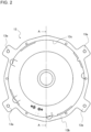
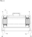
Fig. 2 is a bottom view of themotor case 13 in thepump 100 according to Embodiment 1.Fig. 3 is a sectional view of themotor case 13 in thepump 100 according to Embodiment 1.Fig. 3 is a sectional view of themotor case 13 that is taken along line A-A inFig. 2 . Themotor case 13 forms an outer shell of themotor unit 10. Themotor case 13 has a case circularcylindrical portion 13b that is a portion formed in the shape of a circular cylinder, and houses thestator 12 and therotor 11, with thestator 12 fixed to the inside of themotor case 13. Themotor case 13 is formed in the shape of a cylinder. An innercircumferential surface 13c of the case circularcylindrical portion 13b is brought into contact with and fitted to afit portion 18c of thebracket 18. - The
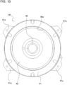
motor case 13 has motor-side engagement portions 13a that project outward in the radial direction of themotor case 13 from an outer surface of the case circularcylindrical portion 13b. The motor-side engagement portions 13a are engaged with respective frame-side engagement portion 41a (seeFig. 10 ) of theframe 40, and the motor-side engagement portion 13a and the frame-side engagement portion 41a are fastened together by fastening tools such as bolts. - As illustrated in
Fig. 1 , theshaft portion 15 is a rod-shaped or pillar-shaped element. Theshaft portion 15 is fixed to therotor 11 such that at a central portion of therotor 11, theshaft portion 15 penetrates therotor 11 in the axial direction of theshaft portion 15. Theshaft portion 15 is fixed to therotor 11 such that an upper part of theshaft portion 15 is inserted in therotor 11. Theshaft portion 15 is fixed to theimpeller 20 such that a lower part of theshaft portion 15 is connected to theimpeller 20. Theshaft portion 15 is rotated by rotation of therotor 11. Theshaft portion 15 transmits a rotatory power of therotor 11 to theimpeller 20, thereby causing theimpeller 20 to rotate. - The
bearing 16 is a ring-shaped element provided around theshaft portion 15. Thebearing 16 is, for example, a ball bearing and supports theshaft portion 15 such that theshaft portion 15 is rotatable. Thebearing 16 is provided between therotor 11 and thebracket 18 in the axial direction of theshaft portion 15. Theshaft portion 15 has a projectingpart 15a that is provided above thebearing 16. The projectingpart 15a of theshaft portion 15 is a flange-shaped portion that projects in the radial direction of theshaft portion 15. Thebearing 16 is provided on an upper part of abottom portion 18b of thebracket 18, which will be described later. - The
bracket 18 is formed in the shape of a column, and supports the bearing 16 in the axial direction of theshaft portion 15. Thebracket 18 is made of resin. Thebracket 18 is provided on an upper portion of theframe 40. Thebracket 18 is fastened to theframe 40 such that a bottom surface of thebracket 18 is located on an upper surface of theframe 40. Thebracket 18 is provided in a lower part of themotor unit 10, that is, part of themotor unit 10 at which thecasing 30 and theframe 40 are located. A configuration of thebracket 18 will be described in detail later. - The
impeller 20 is accommodated in anaccommodation space 31 of thecasing 30, which will be described later, and has a plurality ofblade portions 21. Theblade portions 21 extend in the radial direction with reference to theshaft portion 15 as seen in the axial direction of theshaft portion 15. Theblade portions 21 are plate-shaped elements and are formed, for example, in the shape of an arc as seen in the axial direction of theshaft portion 15. Theblade portions 21 are not limited to the blade portions formed in the shape of an arc but may be formed in other shapes such as linear shapes as seen in the axial direction of theshaft portion 15. - The
impeller 20 is configured such that the liquid is sucked into theimpeller 20 through ablade inlet 22 formed in a central part of theimpeller 20 and the liquid is discharged through anouter slit 23 by a centrifugal force that is generated by rotation of theimpeller 20. Theblade inlet 22 is an opening formed in theimpeller 20, faces aninlet 31a of thecasing 30, and communicates with an inlet-side tube portion 32 of thecasing 30. When being rotated, theimpeller 20 applies a pressure to liquid that flows through theaccommodation space 31. In this case, the liquid in theaccommodation space 31 flows therein while rotating, and is sent to thedischarge outlet 35. - The
casing 30 is hollow, and the liquid flows in thecasing 30. Thecasing 30 forms a flow passage for the liquid between a pipe (not illustrated) connected to thecasing 30 and another pipe (not illustrated) connected to thecasing 30. In this flow passage in thecasing 30, the liquid, such as water, is sent from the first pipe to the second pipe when being given a pressure by theimpeller 20. - The
casing 30 is provided with theaccommodation space 31, the inlet-side tube portion 32, an outlet-side tube portion 33, thesuction inlet 34, and thedischarge outlet 35. Furthermore, thecasing 30 includes an inlet-side connection portion 36 and an outlet-side connection portion 37. Thecasing 30 has thefluid passage 38, which has thesuction inlet 34 at one end of thefluid passage 38 and thedischarge outlet 35 at the other end of thefluid passage 38, and through which the liquid flows. Theimpeller 20 is accommodated in theaccommodation space 31 that is formed in part of thefluid passage 38. Thefluid passage 38 inlcudes theaccommodation space 31, the inlet-side tube portion 32, the outlet-side tube portion 33, thesuction inlet 34, and thedischarge outlet 35. - The
accommodation space 31 is provided in thecasing 30 and accommodates theimpeller 20. Theaccommodation space 31 is a pillared space, and has aninlet 31a formed in its lower side and anoutlet 31b formed in its side. As seen in the axial direction of theshaft portion 15, the side of theaccommodation space 31 is formed in the shape of, for example, part of a spiral that winds outward from the center. - The side where the
inlet 31a is provided as an opening is opposite to a side where themotor unit 10 is located. Theinlet 31a is an inlet through which the liquid flows from the inlet-side tube portion 32 into theaccommodation space 31, and is an end of the inlet-side tube portion 32 through which the liquid flows out of the inlet-side tube portion 32. Theinlet 31a is formed in such a manner as to face part of theimpeller 20 in which theblade inlet 22 is formed. - The inlet-
side tube portion 32 is a portion that forms a conduit between thesuction inlet 34 and theinlet 31a of theaccommodation space 31. Thesuction inlet 34 is formed at one end of the inlet-side tube portion 32, and theinlet 31a of theaccommodation space 31 is formed at the other end of the inlet-side tube portion 32. The inlet-side tube portion 32 is configured such that an axial direction of part of the inlet-side tube portion 32 that adjoins theinlet 31a is a direction along theshaft portion 15 and an axial direction of part of the inlet-side tube portion 32 that adjoins thesuction inlet 34 is a radial direction of theshaft portion 15. That is, the inlet-side tube portion 32 is formed such that its tube axis is curved. - The
suction inlet 34 is an opening provided in a side surface of thecasing 30. Thesuction inlet 34 communicates with theaccommodation space 31 through the inlet-side tube portion 32. The liquid that flows through the first pipe flows into the inlet-side tube portion 32 through thesuction inlet 34, passes through the inlet-side tube portion 32, and flows into theaccommodation space 31. - The
outlet 31b is an opening provided apart from theshaft portion 15 in the radial direction. Theoutlet 31b is an outlet through which the liquid flows out from theaccommodation space 31 into the outlet-side tube portion 33, and is an end of the outlet-side tube portion 33 through which the liquid flows into the outlet-side tube portion 33. Theoutlet 31b is formed to face part of theimpeller 20 in which theslit 23 is formed. - The outlet-
side tube portion 33 is a portion that forms a conduit between thedischarge outlet 35 and theoutlet 31b of theaccommodation space 31. Thedischarge outlet 35 is formed at one end of the outlet-side tube portion 33, and theoutlet 31b of theaccommodation space 31 is formed at the other end of the outlet-side tube portion 33. The outlet-side tube portion 33 extends in the radial direction of theshaft portion 15. - The
discharge outlet 35 is an opening provided in a side surface of thecasing 30. Thedischarge outlet 35 communicates with theaccommodation space 31 through the outlet-side tube portion 33. The liquid that flows out from theaccommodation space 31 flows into the outlet-side tube portion 33 and flows into the other pipe through thedischarge outlet 35. - The
discharge outlet 35 is an opening provided in a side surface of thecasing 30 that is located opposite to thesuction inlet 34 with reference to theaccommodation space 31. It should be noted that the configuration of thecasing 30 is not limited to a configuration in which thedischarge outlet 35 and thesuction inlet 34 are formed in opposite side surfaces. It suffices that thecasing 30 is formed such that as seen in the axial direction of theshaft portion 15, thedischarge outlet 35 and thesuction inlet 34 are located apart from theshaft portion 15 in the radial direction. - The inlet-
side connection portion 36 is a portion formed in the shape of a flange at thesuction inlet 34. The above one pipe through which the liquid flows into thecasing 30 is connected to the inlet-side connection portion 36. The outlet-side connection portion 37 is a portion formed in the shape of a flange at thedischarge outlet 35. The above other pipe through which the liquid flows after flowing out from thecasing 30 is connected to the outlet-side connection portion 37. The inlet-side connection portion 36 and the outlet-side connection portion 37 form side surfaces of thecasing 30. -
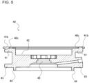
Fig. 4 is a top view of theframe 40 in thepump 100 according to Embodiment 1.Fig. 5 is a sectional view of theframe 40 in thepump 100 according to Embodiment 1. To be more specific,Fig. 5 is a sectional view of theframe 40 that is taken along line B-B inFig. 4 . Theframe 40 will be described with reference toFigs. 1 ,4 , and5 . - The
frame 40 is a column-shaped element that extends in the axial direction of theshaft portion 15. Theframe 40 is partially formed in the shape of a circular cylinder, is provided between themotor unit 10 and the casing in an axial direction of themotor unit 10, and connects themotor unit 10 and thecasing 30. Theframe 40 is provided on an upper part of thecasing 30. Theframe 40 connects the lower part of themotor unit 10 and the upper part of thecasing 30. A lower part of theframe 40 is fastened to the upper part of thecasing 30 by fastening tools such as bolts. An upper part of theframe 40 is fastened to themotor case 13 by fastening tools such as bolts. - At the upper part of the
frame 40, an upper ring-shapedportion 41 and anengagement portion 42 are formed. The upper ring-shapedportion 41 is formed in the shape of a flange, and extends in the radial direction as seen in the axial direction of theshaft portion 15. The upper ring-shapedportion 41 is formed, for example, in the shape of a ring. - The upper ring-shaped
portion 41 has a circularcylindrical portion 41b that projects toward themotor unit 10 along an outer circumferential edge of the upper ring-shapedportion 41. The circularcylindrical portion 41b is formed in the shape of a circular cylinder formed at the upper part of theframe 40. The circularcylindrical portion 41b has an innercircumferential surface 40c that is brought into contact with thefit portion 18c that is formed on an outer circumferential surface of the projectingpart 182, which will be described later. - At the upper ring-shaped
portion 41, the projectingpart 182 of thebracket 18, which will be described later, is provided. At the upper ring-shapedportion 41, the frame-side engagement portions 41a are formed in such a manner as to project outward in the radial direction. The frame-side engagement portion 41a are engaged with the motor-side engagement portions 13a of themotor case 13, and the frame-side engagement portions 41a and the motor-side engagement portions 13a are fastened together by the fastening tools such as bolts. - At the lower part of the
frame 40, a lower ring-shapedportion 43 and alower engagement portion 44 are formed. The lower ring-shapedportion 43 is formed in the shape of a flange, and extends in the radial direction as seen in the axial direction of theshaft portion 15. The lower ring-shapedportion 43 is formed, for example, in the shape of a ring. The lower ring-shapedportion 43 is engaged with the upper part of thecasing 30, and the lower ring-shapedportion 43 and thecasing 30 are fastened together by fastening tools such as bolts. Thelower engagement portion 44 is formed in the shape of a cylinder and located at a lower position than the lower ring-shapedportion 43. Thelower engagement portion 44 is inserted into an opening formed in thecasing 30 and fitted into thecasing 30. - The
engagement portion 42 is an upper surface portion of theframe 40 that is recessed toward thecasing 30. Theengagement portion 42 forms a step with reference to the upper ring-shapedportion 41. At theengagement portion 42, thebottom portion 18b of thebracket 18, which will be described later, is provided. - In a central part of the
frame 40, aframe shaft hole 45 is formed. Theframe shaft hole 45 forms a through hole that extends in the axial direction of theshaft portion 15. An opening diameter of theframe shaft hole 45 is larger than a diameter of theshaft portion 15 of therotor 11. In thepump 100, theshaft portion 15 of therotor 11 is inserted into theframe shaft hole 45 and extends through theframe 40. - In the upper surface of the
frame 40,screw holes 40d are formed. In thepump 100, thebracket 18 and theframe 40 are fastened together byfastening tools 46 inserted in fastener holes 187 (seeFig. 6 ) of thebracket 18 and thescrew holes 40d. -
Fig. 6 is a top view of thebracket 18 according to Embodiment 1.Fig. 7 is a sectional view of thebracket 18 according to Embodiment 1. To be more specific,Fig. 7 is a sectional view of thebracket 18 that is taken along line C-C inFig. 6 . Thebracket 18 will be described with reference toFigs. 1 to 7 . - The
bracket 18 supports theshaft portion 15 and therotor 11 through thebearing 16. Thebracket 18 is used to ensure concentricity between themotor unit 10 and part of thecasing 30 that forms theaccommodation space 31. Thebracket 18 is formed in the shape of a circular cylinder having a bottom and includes an outercircumferential wall 18a that forms a cylindrical side wall and thebottom portion 18b that forms a disc-shaped bottom wall. - The
bracket 18 has thefit portion 18c at an outer circumferential surface of the outercircumferential wall 18a. Thefit portion 18c is configured to perform shaft alignment between thestator 12 of themotor unit 10 and theframe 40. Thefit portion 18c is part of thepump 100 that is fitted to themotor case 13 and theframe 40. Thefit portion 18c forms part of an outer circumferential surface of thebracket 18 and is brought into contact with and fitted to an innercircumferential surface 13c (seeFigs. 2 and3 ) of the part of themotor case 13 that is formed in the shape of a circular cylinder and an innercircumferential surface 40c (seeFigs. 4 and5 ) of part of theframe 40 that is formed in the shape of a circular cylinder. - The
pump 100 is provided such that in a state in which a fitted portion between thebracket 18 and themotor case 13 and a fitted portion between thebracket 18 and theframe 40 are located on the same circular cylinder, with thefit portion 18c fitted to themotor case 13 and theframe 40. That is, thepump 100 is formed such that a circular cylindrical surface on which the fitted portion between thebracket 18 and themotor case 13 is located and a circular cylindrical surface on which the fitted portion between thebracket 18 and theframe 40 are located on the same circular cylinder. - The
bracket 18 of Embodiment 1 has abody part 181 formed in the shape of a column and the projectingpart 182 that projects outward from thebody part 181. Thebody part 181 has acircumferential wall 181a and thebottom portion 18b and is formed in the shape of a circular cylinder having a bottom. Thecircumferential wall 181a forms an outer circumferential surface of thebody part 181 that is formed in the shape of a column, and thebottom portion 18b forms a bottom surface of thebody part 181 formed in the shape of a column. Thecircumferential wall 181a and the projectingpart 182 form the outercircumferential wall 18a of thebracket 18. - The
body part 181 has thehousing portion 183. Thehousing portion 183 is a recessed portion in thebody part 181 in the axial direction of theshaft portion 15. Thehousing portion 183 is formed at a surface at which themotor unit 10 is located in thepump 100. Thehousing portion 183 is formed in a central portion of thebody part 181 as seen in the axial direction of theshaft portion 15. - In the
housing portion 183, theshaft portion 15 and thebearing 16 are provided. Thehousing portion 183 receives thebearing 16 provided and supports thebearing 16. - The
bracket 18 has ashaft hole 186 formed therein. Theshaft hole 186 forms a through hole extending in the axial direction of theshaft portion 15. Theshaft hole 186 is formed in a center section of thebody part 181. Theshaft hole 186 is formed in thebottom portion 18b of thehousing portion 183. An opening diameter of theshaft hole 186 is larger than the diameter of theshaft portion 15 of therotor 11. In thepump 100, theshaft portion 15 of therotor 11 is inserted into theshaft hole 186 and extends through thebottom portion 18b. - The projecting
part 182 is formed to project outward from an outer circumferential surface of thecircumferential wall 181a. The projectingpart 182 is formed to extend from the central portion of thebody part 181 in the radial direction as seen in the axial direction of theshaft portion 15. The projectingpart 182 is formed in the shape of a circular ring as seen in the axial direction of theshaft portion 15. The projectingpart 182 is formed in the shape of a circular cylinder. Thebracket 18 of Embodiment 1 has thefit portion 18c that is formed at a distal end portion of the projectingpart 182 in a direction in which the projectingpart 182 projects, that is, at the outer circumferential surface of the projectingpart 182. - In the
bottom portion 18b of thehousing portion 183, the fastener holes 187 are formed. The fastener holes 187 forms through holes that extend in the axial direction of theshaft portion 15. The fastener holes 187, through which thefastening tools 46 such as screws (seeFig. 1 ) are inserted, are used to cause thebracket 18 and theframe 40 to be fastened together. Although thebracket 18 as illustrated inFig. 6 has fourfastener holes 187, the number of fastener holes 187 is not limited to 4 but may be smaller than or equal to 3 or may be larger than or equal to 5. - Operation of the
pump 100 will be described. In thepump 100, themotor unit 10 drives therotor 11 to rotate it, and when therotor 11 rotates, theimpeller 20, which is connected to theshaft portion 15, is rotated. Thecasing 30 has thesuction inlet 34 formed at one end of a refrigerant flow passage formed in thecasing 30 and thedischarge outlet 35 formed at the other end of the refrigerant flow passage. In thepump 100, when theimpeller 20 rotates, liquid in thepump 100 is caused to flow from thesuction inlet 34 to thedischarge outlet 35, thereby transferring the liquid in thecasing 20. - In this case, liquid that flows from a pipe connected to the inlet-
side connection portion 36 passes through thesuction inlet 34, and then flows in the inlet-side tube portion 32. The liquid that has flowed in the inlet-side tube portion 32 passes through theinlet 31a and flows into theaccommodation space 31. The liquid that has flowed into theaccommodation space 31 passes through theblade inlet 22 of theimpeller 20 and is given a centrifugal force by rotation of theimpeller 20. Then, the liquid that has been given the centrifugal force is discharged from theslit 23 of theimpeller 20, flows along a spiral-shaped inner side of theaccommodation space 31, passes through theoutlet 31b, and flows into the outlet-side tube portion 33. The liquid that has flowed into the outlet-side tube portion 33 passes through thedischarge outlet 35 and is discharged to a pipe connected to the outlet-side connection portion 37. - In operation of the
pump 100, when the space between theimpeller 20 and thecasing 30 is large, pressured water from a discharge side leaks toward a suction side and causes deterioration of the performance of the pump, and it is therefore preferable that the space between theimpeller 20 and thecasing 30 be reduced. It is possible to reduce the space between theimpeller 20 and thecasing 30 by reducing the degree of misalignment between the center of themotor unit 10 and that of thecasing 30, as theimpeller 20 is mounted in themotor unit 10. In order that the degree of misalignment between the centers of themotor unit 10 and thecasing 30 be reduced, it is conceivable that the degree of misalignment between the centers of themotor unit 10 and theframe 40 can be reduced, as themotor unit 10 and thecasing 30 are connected to each other by theframe 40. - A
pump 100 includes theframe 40 having a portion formed in the shape of a circular cylinder and connecting themotor unit 10 with thecasing 30. Furthermore, thepump 100 includes thebracket 18 made of resin, formed in the shape of a circular cylinder having a bottom, provided on the upper portion of theframe 40, and supports the bearing 16 in the axial direction of theshaft portion 15. Thebracket 18 includes the outercircumferential wall 18a that forms a cylindrical wall and thebottom portion 18b that forms a bottom wall. Thebracket 18 has, at the outer circumferential surface of the outercircumferential wall 18a, thefit portion 18c that is brought into contact with and fitted to the innercircumferential surface 13c of the portion of themotor case 13 that is formed in the shape of a circular cylinder and the innercircumferential surface 40c of the portion of the frame 40that is formed in the shape of a circular cylinder. Thepump 100 is configured such that the fitted portion between thebracket 18 and themotor case 13 and the fitted portion between thebracket 18 and theframe 40 are located on the same circular cylinder, with thefit portion 18c fitted to themotor case 13 and the frame. In thepump 100, since shaft alignment between themotor case 13 and theframe 40 is performed on the same circular cylinder by thefit portion 18c of thebracket 18 made of resin, it is possible to reduce the degree of misalignment between the centers of themotor unit 10 and theframe 40. Furthermore, since thebracket 18 is provided on the upper portion of theframe 40, a sufficient strength of thebracket 18 can be ensured by theframe 40. It is therefore possible to reduce the number of components to be used, while ensuring the concentricity between themotor unit 10 and theframe 40, and to simplify the manufacturing processes. - The following description is made with respect to the case where the fitted portion (hereinafter referred to as "fitted portion A") between the
motor case 13 and thebracket 18 and the fitted portion (hereinafter referred to as "fitted portion B") between theframe 40 and thebracket 18 are provided separately from each other. In addition to the degree of misalignment between the centers of themotor case 13 and the fitted portion A and the degree of misalignment between the centers of theframe 40 and the fitted portion B, the degree of misalignment between the centers of the fitted portion A and the fitted portion B is added, as a result of which the misalignment occurs for the above three causes, thus increasing the degree of misalignment between the centers of themotor unit 10 and theframe 40. In thepump 100, misalignment between the centers of the fitted portion A and the fitted portion B is eliminated since themotor case 13 and theframe 40 are fitted together on the same circular cylinder, thus reducing the number of causes of the misalignment. Accordingly, the degree of misalignment between the centers of themotor case 13 and theframe 40 is reduced. - In the
pump 100, since thebracket 18 has the fitted portion with themotor unit 10 and the fitted portion with theframe 40 that are located on the same circular cylinder, it is possible to ensure the concentricity between themotor unit 10 and theframe 40 and simplify the shape of thebracket 18. - Furthermore, since the
pump 100 does not require, in addition to thebracket 18 made of resin, an additional element such as a sheet metal bracket for receiving a motor load, it is possible to prevent the incurrence of additional costs such as manufacturing costs and material costs. Therefore, in thepump 100, it is possible to reduce the number of components to be used and also reduce costs such as manufacturing costs and material costs, as compared with the case where a sheet metal is added. - In the pump of Patent Literature 1, the shapes of components are complicated due to the shapes of the projections of the resin bracket that is provided to perform shaft alignment between the motor and the frame, and the structure of a mold for molding the resin bracket is also complicated. Thus, the mold is not easily manufactured. In the
pump 100 of Embodiment 1, the fitted portion between thebracket 18 and themotor case 13 and the fitted portion between thebracket 18 and theframe 40 are located on the same circular cylinder, and the projections of thebracket 18 are eliminated, thereby simplifying the shape of thebracket 18. In thepump 100 of Embodiment 1, thebracket 18 is formed in the shape of a column and provided on the upper portion of theframe 40, and the shape of thebracket 18 is simplified while the concentricity between themotor unit 10 and theframe 40 is ensured. Therefore, in thepump 100, it is possible to simplify the structure of the mold for molding thebracket 18 and easily manufacture the mold. - Furthermore, the
bracket 18 has thefastener hole 187 that extends as a through hole in the axial direction of theshaft portion 15, theframe 40 has thescrew holes 40d formed in its upper surface. In thepump 100, thebracket 18 and theframe 40 are fastened together by thefastening tools 46 inserted in the fastener holes 187 and thescrew holes 40d. Thepump 100 is configured such that theframe 40 receives a motor load through thebracket 18, and can ensure sufficient strength without including a reinforcing element for receiving a motor load, such as a sheet metal bracket. -
Fig. 8 is a top view of abracket 118 according to Embodiment 2.Fig. 9 is a sectional view of thebracket 118 according to Embodiment 2.Fig. 10 is a top view of aframe 40 in thepump 100 according to Embodiment 2. Thebracket 118 according to Embodiment 2 will be described with reference toFigs. 8 and9 , and theframe 40 according to Embodiment 2 will be described with reference toFig. 10 . Regarding Embodiment 2, components that have the same configurations as those in thebracket 18 according to Embodiment 1 will be denoted by the same reference signs, and their descriptions will be omitted. - The
bracket 118 is configured to support theshaft portion 15 and therotor 11 through thebearing 16. Thebracket 118 is made of resin. Thebracket 118 is used to ensure the concentricity between themotor unit 10 and part of thecasing 30 that forms theaccommodation space 31. Thebracket 118 is formed in the shape of a circular cylinder having a bottom and includes an outercircumferential wall 18a that forms a cylindrical wall and abottom portion 18b that forms a bottom wall. - The
bracket 118 of Embodiment 2 has abody part 181 formed in the shape of a column and a projectingpart 182 that projects outward from thebody part 181. Thebody part 181 has acircumferential wall 181a and thebottom portion 18b and is formed in the shape of a circular cylinder having a bottom. Thebody part 181 has ahousing portion 183. Thehousing portion 183 includes thecircumferential wall 181a and thebottom portion 18b. Thebracket 118 has ashaft hole 186. - The
bracket 118 has afit portion 18c at the outercircumferential wall 18a. Thebracket 118 according to Embodiment 2 has thefit portion 18c formed at an outer circumferential surface of thecircumferential wall 181a. Part of thecircumferential wall 181a that is located at a higher position than the projectingpart 182 is a stator-side fit portion 18c1, and part of thecircumferential wall 181a that is located at a lower position than the projectingpart 182 is a frame-side fit portion 18c2. - The stator-side fit portion 18c1 is brought into contact with and fitted to an inner circumferential surface (not illustrated) of the
motor case 13. The frame-side fit portion 18c2 is brought into contact with and fitted to an innercircumferential surface 40e of theframe 40 of Embodiment 2. - The projecting
part 182 is formed to project outward from the outer circumferential surface of thecircumferential wall 181a. The projectingpart 182 is formed to extend from a central part of thebody part 181 as seen in the axial direction of theshaft portion 15. The projectingpart 182 is formed in the shape of a ring as seen in the axial direction of theshaft portion 15. The projectingpart 182 is held between themotor case 13 and theframe 40 in the axial direction of theshaft portion 15. - As illustrated in
Fig. 8 , thebracket 118 has no fastener holes 187 formed in thebottom portion 18b. Furthermore, as illustrated inFig. 10 , theframe 40 of Embodiment 2 has noscrew holes 40d. Thebracket 118, which receives a load of therotor 11, is configured such that thebottom portion 18b is located at an upper surface of theframe 40 and thebracket 118 is held between themotor case 13 and theframe 40. - The outer
circumferential wall 18a of thebracket 118 includes the projectingpart 182 that projects in the radial direction with reference to theshaft portion 15 and that is formed in the shape of a ring. In thepump 100, themotor case 13 and theframe 40 are fastened together, with the projectingpart 182 held therebetween in the axial direction of theshaft portion 15. The projectingpart 182 is located, for example, between the upper ring-shapedportion 41 of theframe 40 and part of an internal wall of themotor case 13. - The
fit portion 18c is formed in the shape of a circular cylinder, fitted to an inner circumferential surface of themotor case 13 at a higher position than the projectingpart 182, and fitted to an innercircumferential surface 40e of theframe 40 at a lower position than the projectingpart 182. The innercircumferential surface 40e forms an inner surface of theengagement portion 42 of theframe 40 of Embodiment 2. - In the
pump 100 of Embodiment 2, a stator-side fit portion 18c1 and a frame-side fit portion 18c2 are provided separately as afit portion 18c, and a projectingpart 182 that is larger in outside diameter than thecircumferential wall 181a is provided between the stator-side fit portion 18c1 and the frame-side fit portion 18c2. Since thepump 100 of Embodiment 2 is configured such that the projectingpart 182 is held between themotor case 13 and theframe 40, themotor case 13 and theframe 40 are fastened together. Thus, in thepump 100 of Embodiment 2, it is not necessary to provide afastening tool 46 such as a bolt for fastening thebracket 118 and theframe 40 together. Therefore, in thepump 100 of Embodiment 2, it is possible to reduce the number of components such as afastening tool 46 for fastening thebracket 18 and theframe 40 together. In addition, thepump 100 of Embodiment 2 can obtain advantages that are similar to those of thepump 100 of Embodiment 1. -
Fig. 11 is a sectional view of abracket frame 218 according to Embodiment 3. Thebracket frame 218 according to Embodiment 3 will be described with reference toFig. 11 . It should be noted that regarding Embodiment 3, components that have the same configurations as those of thebracket 18 according to Embodiment 1 and/or those of thebracket 118 according to Embodiment 2 will be denoted by the same reference signs, and their descriptions will be omitted. - The
motor unit 10 includes abracket frame 218 in place of thebracket 18 of Embodiment 1. Thebracket frame 218 is formed in the shape of a column, supports the bearing 16 in the axial direction of theshaft portion 15, and connects themotor unit 10 and thecasing 30. Thebracket frame 218 is made of resin. - The
bracket frame 218 is a combination of theframe 40 and thebracket 18 of Embodiment 1 or thebracket 118 of Embodiment 2; that is, theframe 40 is formed integral with thebracket 18 of Embodiment 1 or thebracket 118 of Embodiment 2, thereby forming thebracket frame 218. In each of Embodiments 1 and 2, thebracket frame 40 are separate components. If dimensional constraints on a mold are not added or a problem related to the strength of therotor 11 against a load does not arise, thebracket 18 and theframe 40 may be replaced by thebracket frame 218, which is an integrated component made of resin. - The
bracket frame 218 has abody part 181 formed in the shape of a column and a projectingpart 182 that projects outward from thebody part 181. Thebracket frame 218 has an outercircumferential wall 18a that forms a cylindrical wall. Thebracket frame 218 has, at an outer circumferential surface of the outercircumferential wall 18a, afit portion 18c that is brought into contact with and fitted to an inner circumferential surface of part of themotor case 13 that is formed in the shape of a circular cylinder. Thebracket frame 218 has thefit portion 18c that is formed at a distal end portion of the projectingpart 182 in a direction where the projectingpart 182 projects, that is, at the outer circumferential surface of the projectingpart 182. - The
bracket frame 218 is configured such that the projectingpart 182 and an upper ring-shapedportion 41 are formed integral with each other. The outside diameter of the upper ring-shapedportion 41 is larger than the outside diameter of the projectingpart 182. Accordingly, thebracket frame 218 has a step that is formed between the upper ring-shapedportion 41 and the projectingpart 182, and the outer circumferential surface of the projectingpart 182 is recessed inward relative to an outer circumferential surface of the upper ring-shapedportion 41. - The
bracket frame 218 has ahousing portion 183. In thehousing portion 183, ashaft hole 186 is formed below thehousing portion 183, and aframe shaft hole 45 is formed below theshaft hole 186. - At lower part of the
bracket frame 218, a lower ring-shapedportion 43 is formed, and at a lower surface of thebracket frame 218, alower engagement portion 44 is formed. - The
pump 100 includes thebracket frame 218 that is made of resin, formed in the shape of a column, supports the bearing 16 in the axial direction of theshaft portion 15, and connects themotor unit 10 and thecasing 30. Thebracket frame 218 has, at the outer circumferential surface of the outercircumferential wall 18a, thefit portion 18c that is brought into contact with and fitted to the inner circumferential surface of the portion of themotor case 13 that is formed in the shape of a circular cylinder. - In the
pump 100 of Embodiment 3, thebracket 18 of Embodiment 1 or 2 and theframe 40 are formed integral with each other, and it is therefore unnecessary to consider the concentricity between thebracket 18 and theframe 40. Therefore, in thepump 100 of Embodiment 3, it suffices to consider the concentricity between thebracket frame 218 and themotor case 13, and the degree of misalignment between the centers of themotor unit 10 and thecasing 30 can be easily reduced, as compared with thepumps 100 of Embodiments 1 and 2. - While each of the
pumps 100 of Embodiments 1 and 2 requires two components, that is, thebracket 18 and theframe 40, thepump 100 of Embodiment 3 includes thebracket frame 218, which serves as both thebracket 18 and theframe 40. Therefore, in the pump of Embodiment 3, it is possible to reduce the number of components, as compared with thepumps 100 of Embodiments 1 and 2. In addition, thepump 100 of Embodiment 3 can obtains advantages that are similar to those of thepumps 100 of Embodiments 1 and 2. - 10: motor unit, 11: rotor, 12: stator, 13: motor case, 13a: motor-side engagement portion, 13b: case circular cylindrical portion, 13c: inner circumferential surface, 15: shaft portion, 15a: projecting part, 16: bearing, 18: bracket, 18a: outer circumferential wall, 18b: bottom portion, 18c: fit portion, 18c1: stator-side fit portion, 18c2: frame-side fit portion, 20: impeller, 21: blade portion, 22: blade inlet, 23: slit, 30: casing, 31: accommodation space, 31a: inlet, 31b: outlet, 32: inlet-side tube portion, 33: outlet-side tube portion, 34: suction inlet, 35: discharge outlet, 36: inlet-side connection portion, 37: outlet-side connection portion, 38: fluid passage, 40: frame, 40c: inner circumferential surface, 40d: screw hole, 40e: inner circumferential surface, 41: upper ring-shaped portion, 41a: frame-side engagement portion, 41b: circular cylindrical portion, 42: engagement portion, 43: lower ring-shaped portion, 44: lower engagement portion, 45: frame shaft hole, 46: fastening tool, 100: pump, 118: bracket, 181: body part, 181a: circumferential wall, 182: projecting part, 183: housing portion, 186: shaft hole, 187: fastener hole, 218: bracket frame
Claims (4)
- A pump comprising:a motor unit serving as a driving unit;an impeller configured to rotate liquid upon receiving output from the motor unit and move the liquid by applying a centrifugal force to the liquid;a casing having a fluid passage therein that has a suction inlet at one end of the flow passage and a discharge outlet at an other end of the flow passage and through which the liquid flows, the casing having an accommodation space that is provided in part of the fluid passage and in which the impeller is accommodated; anda frame having a portion formed in the shape of a circular cylinder, the frame being provided between the motor unit and the casing in an axial direction of the motor unit and connecting the motor unit and the casing,whereinthe motor unit includesa stator formed in the shape of a circular cylinder,a rotor to which a shaft portion is fixed, the rotor being rotatably provided in a hollow portion of the stator, the shaft portion being connected to the impeller,a motor case having a portion formed in the shape of a circular cylinder, the motor case housing the stator and the rotor, with the stator fixed to inside of the motor case,a bearing supporting the shaft portion in such a manner as to allow the shaft portion to be rotated, anda bracket made of resin and formed in the shape of a circular cylinder having a bottom, the bracket including an outer circumferential wall that forms a cylindrical wall and a bottom portion that forms a bottom wall, the bracket being provided on an upper portion of the frame and supporting the bearing in an axial direction of the shaft portion,the bracket has a fit portion that is formed at an outer circumferential surface of the outer circumferential wall and that is brought into contact with and fitted to an inner circumferential surface of the portion of the motor case that is formed in the shape of the circular cylinder and an inner circumferential surface of the portion of the frame that is formed in the shape of the circular cylinder, anda fitted portion between the bracket and the motor case and a fitted portion between the bracket and the frame are provided on the same circular cylinder, with the fit portion fitted to the motor case and the frame.
- The pump of claim 1, whereinthe bracket has a fastener hole that extends through the bracket in the axial direction of the shaft portion,the frame has a screw hole formed in an upper surface of the frame, andthe bracket and the frame are fastened together by a fastening tool inserted in the fastener hole and the screw hole.
- The pump of claim 1, whereinthe outer circumferential wall of the bracket has a projecting part that is formed in the shape of a ring and that projects in a radial direction from the shaft portion,the motor case and the frame are fastened together, with the projecting part held between the motor case and the frame in the axial direction of the shaft portion, andthe fit portion is formed in the shape of a circular cylinder, fitted to an inner circumferential surface of the motor case at a higher position than the projecting part, and fitted to an inner circumferential surface of the frame at a lower position than the projecting part.
- A pump comprising:a motor unit serving as a driving unit;an impeller configured to rotate liquid upon receiving output from the motor unit and move the liquid by applying a centrifugal force to the liquid; anda casing having a fluid passage therein that has a suction inlet at one end of the fluid passage and a discharge outlet at an other end of the fluid passage and through which the liquid flows, the casing having an accommodation space that is provided in part of the fluid passage and in which the impeller is accommodated,whereinthe motor unit includesa stator formed in the shape of a circular cylinder,a rotor to which a shaft portion is fixed, the rotor being rotatably provided in a hollow portion of the stator, the shaft portion being connected to the impeller,a motor case having a portion formed in the shape of a circular cylinder the motor case housing the stator and the rotor, with the stator fixed to inside of the motor case,a bearing supporting the shaft portion in such a manner as to allow the shaft portion to be rotated, anda bracket frame made of resin, supporting the bearing in an axial direction of the shaft portion, and connecting the motor unit and the casing, andthe bracket frame has, at an outer circumferential surface of an outer circumferential wall, a fit portion that is brought into contact with and fitted to an inner circumferential surface of the portion of the motor case that is formed in the shape of the circular cylinder.
Applications Claiming Priority (1)
| Application Number | Priority Date | Filing Date | Title |
|---|---|---|---|
| PCT/JP2022/018506 WO2023203743A1 (en) | 2022-04-22 | 2022-04-22 | Pump |
Publications (2)
| Publication Number | Publication Date |
|---|---|
| EP4513041A1 true EP4513041A1 (en) | 2025-02-26 |
| EP4513041A4 EP4513041A4 (en) | 2025-05-21 |
Family
ID=88419644
Family Applications (1)
| Application Number | Title | Priority Date | Filing Date |
|---|---|---|---|
| EP22938543.0A Withdrawn EP4513041A4 (en) | 2022-04-22 | 2022-04-22 | PUMP |
Country Status (3)
| Country | Link |
|---|---|
| EP (1) | EP4513041A4 (en) |
| JP (1) | JPWO2023203743A1 (en) |
| WO (1) | WO2023203743A1 (en) |
Family Cites Families (8)
| Publication number | Priority date | Publication date | Assignee | Title |
|---|---|---|---|---|
| JPS50148102U (en) * | 1974-05-24 | 1975-12-09 | ||
| US4810174A (en) * | 1986-12-12 | 1989-03-07 | Flint & Walling, Inc. | Motor and pump assembly |
| US4810175A (en) * | 1987-08-12 | 1989-03-07 | Magnetek, Inc. | Hermetic motor bearing assembly |
| JPH07177699A (en) * | 1993-12-22 | 1995-07-14 | Ebara Corp | Cantilever bearing type motor and pump employing it |
| JPH11294395A (en) * | 1998-04-13 | 1999-10-26 | Ebara Corp | Submersible motor |
| JP2003227490A (en) * | 2002-02-04 | 2003-08-15 | Ebara Corp | Submerged pump |
| JP5183502B2 (en) * | 2009-01-08 | 2013-04-17 | 株式会社鶴見製作所 | Submersible electric pump |
| JP7297152B2 (en) | 2020-04-09 | 2023-06-23 | 三菱電機株式会社 | pump |
-
2022
- 2022-04-22 JP JP2024516025A patent/JPWO2023203743A1/ja active Pending
- 2022-04-22 WO PCT/JP2022/018506 patent/WO2023203743A1/en not_active Ceased
- 2022-04-22 EP EP22938543.0A patent/EP4513041A4/en not_active Withdrawn
Also Published As
| Publication number | Publication date |
|---|---|
| JPWO2023203743A1 (en) | 2023-10-26 |
| WO2023203743A1 (en) | 2023-10-26 |
| EP4513041A4 (en) | 2025-05-21 |
Similar Documents
| Publication | Publication Date | Title |
|---|---|---|
| KR100402063B1 (en) | Pumps with improved flow path | |
| JP2958218B2 (en) | pump | |
| EP3239526B1 (en) | Electrically driven scroll compressor | |
| CN110162156B (en) | cooling device | |
| JP2015068245A (en) | Scroll type fluid machine | |
| US20250129787A1 (en) | Pump unit | |
| KR20150100297A (en) | Electric pump | |
| EP3332126A1 (en) | Magnetic drive, seal-less pump | |
| WO2022201731A1 (en) | Motor pump, pump unit, and balance adjustment method for impeller of motor pump | |
| EP4513041A1 (en) | Pump | |
| JP6944853B2 (en) | Electric compressor | |
| EP0648934B1 (en) | Full-circumferential flow pump | |
| US7040875B2 (en) | Refrigerant pump with rotors in bearing | |
| US12110891B2 (en) | Scroll compressor | |
| JP4972984B2 (en) | Double suction centrifugal pump, impeller thereof, and manufacturing method of impeller | |
| US20230336047A1 (en) | Fluid machine | |
| SU1682632A1 (en) | Dynamic electrical pump | |
| KR20100028903A (en) | A underwater pump | |
| JP5785733B2 (en) | Pump device | |
| KR20220055145A (en) | Air cooling type in-wheel motor apparatus | |
| CN220302400U (en) | Impeller high-precision assembly structure | |
| JP3210635B2 (en) | Canned motor and pump using the canned motor | |
| KR100518027B1 (en) | Casing of pump motor | |
| CN213450827U (en) | Three-point support vertical refrigerant pump | |
| EP1674733B1 (en) | Water pump |
Legal Events
| Date | Code | Title | Description |
|---|---|---|---|
| STAA | Information on the status of an ep patent application or granted ep patent |
Free format text: STATUS: THE INTERNATIONAL PUBLICATION HAS BEEN MADE |
|
| PUAI | Public reference made under article 153(3) epc to a published international application that has entered the european phase |
Free format text: ORIGINAL CODE: 0009012 |
|
| STAA | Information on the status of an ep patent application or granted ep patent |
Free format text: STATUS: REQUEST FOR EXAMINATION WAS MADE |
|
| 17P | Request for examination filed |
Effective date: 20240909 |
|
| AK | Designated contracting states |
Kind code of ref document: A1 Designated state(s): AL AT BE BG CH CY CZ DE DK EE ES FI FR GB GR HR HU IE IS IT LI LT LU LV MC MK MT NL NO PL PT RO RS SE SI SK SM TR |
|
| REG | Reference to a national code |
Ref country code: DE Ref legal event code: R079 Free format text: PREVIOUS MAIN CLASS: F04D0029600000 Ipc: F04D0029046000 |
|
| A4 | Supplementary search report drawn up and despatched |
Effective date: 20250422 |
|
| RIC1 | Information provided on ipc code assigned before grant |
Ipc: F04D 29/42 20060101ALI20250414BHEP Ipc: F04D 1/00 20060101ALI20250414BHEP Ipc: F04D 29/02 20060101ALI20250414BHEP Ipc: F04D 13/06 20060101ALI20250414BHEP Ipc: F04D 29/62 20060101ALI20250414BHEP Ipc: F04D 29/046 20060101AFI20250414BHEP |
|
| STAA | Information on the status of an ep patent application or granted ep patent |
Free format text: STATUS: THE APPLICATION HAS BEEN WITHDRAWN |
|
| DAV | Request for validation of the european patent (deleted) | ||
| DAX | Request for extension of the european patent (deleted) | ||
| 18W | Application withdrawn |
Effective date: 20250718 |