EP4513021A1 - Fuel system for dual use gas turbine engine main fuel pump - Google Patents
Fuel system for dual use gas turbine engine main fuel pump Download PDFInfo
- Publication number
- EP4513021A1 EP4513021A1 EP24193114.6A EP24193114A EP4513021A1 EP 4513021 A1 EP4513021 A1 EP 4513021A1 EP 24193114 A EP24193114 A EP 24193114A EP 4513021 A1 EP4513021 A1 EP 4513021A1
- Authority
- EP
- European Patent Office
- Prior art keywords
- pump
- fuel
- main pump
- fluid communication
- line
- Prior art date
- Legal status (The legal status is an assumption and is not a legal conclusion. Google has not performed a legal analysis and makes no representation as to the accuracy of the status listed.)
- Pending
Links
Images

Classifications
-
- F—MECHANICAL ENGINEERING; LIGHTING; HEATING; WEAPONS; BLASTING
- F02—COMBUSTION ENGINES; HOT-GAS OR COMBUSTION-PRODUCT ENGINE PLANTS
- F02C—GAS-TURBINE PLANTS; AIR INTAKES FOR JET-PROPULSION PLANTS; CONTROLLING FUEL SUPPLY IN AIR-BREATHING JET-PROPULSION PLANTS
- F02C7/00—Features, components parts, details or accessories, not provided for in, or of interest apart form groups F02C1/00 - F02C6/00; Air intakes for jet-propulsion plants
- F02C7/22—Fuel supply systems
- F02C7/236—Fuel delivery systems comprising two or more pumps
-
- F—MECHANICAL ENGINEERING; LIGHTING; HEATING; WEAPONS; BLASTING
- F02—COMBUSTION ENGINES; HOT-GAS OR COMBUSTION-PRODUCT ENGINE PLANTS
- F02C—GAS-TURBINE PLANTS; AIR INTAKES FOR JET-PROPULSION PLANTS; CONTROLLING FUEL SUPPLY IN AIR-BREATHING JET-PROPULSION PLANTS
- F02C7/00—Features, components parts, details or accessories, not provided for in, or of interest apart form groups F02C1/00 - F02C6/00; Air intakes for jet-propulsion plants
- F02C7/22—Fuel supply systems
-
- F—MECHANICAL ENGINEERING; LIGHTING; HEATING; WEAPONS; BLASTING
- F02—COMBUSTION ENGINES; HOT-GAS OR COMBUSTION-PRODUCT ENGINE PLANTS
- F02C—GAS-TURBINE PLANTS; AIR INTAKES FOR JET-PROPULSION PLANTS; CONTROLLING FUEL SUPPLY IN AIR-BREATHING JET-PROPULSION PLANTS
- F02C7/00—Features, components parts, details or accessories, not provided for in, or of interest apart form groups F02C1/00 - F02C6/00; Air intakes for jet-propulsion plants
- F02C7/26—Starting; Ignition
-
- F—MECHANICAL ENGINEERING; LIGHTING; HEATING; WEAPONS; BLASTING
- F02—COMBUSTION ENGINES; HOT-GAS OR COMBUSTION-PRODUCT ENGINE PLANTS
- F02C—GAS-TURBINE PLANTS; AIR INTAKES FOR JET-PROPULSION PLANTS; CONTROLLING FUEL SUPPLY IN AIR-BREATHING JET-PROPULSION PLANTS
- F02C7/00—Features, components parts, details or accessories, not provided for in, or of interest apart form groups F02C1/00 - F02C6/00; Air intakes for jet-propulsion plants
- F02C7/26—Starting; Ignition
- F02C7/268—Starting drives for the rotor, acting directly on the rotor of the gas turbine to be started
- F02C7/27—Fluid drives
-
- F—MECHANICAL ENGINEERING; LIGHTING; HEATING; WEAPONS; BLASTING
- F02—COMBUSTION ENGINES; HOT-GAS OR COMBUSTION-PRODUCT ENGINE PLANTS
- F02C—GAS-TURBINE PLANTS; AIR INTAKES FOR JET-PROPULSION PLANTS; CONTROLLING FUEL SUPPLY IN AIR-BREATHING JET-PROPULSION PLANTS
- F02C7/00—Features, components parts, details or accessories, not provided for in, or of interest apart form groups F02C1/00 - F02C6/00; Air intakes for jet-propulsion plants
- F02C7/32—Arrangement, mounting, or driving, of auxiliaries
-
- F—MECHANICAL ENGINEERING; LIGHTING; HEATING; WEAPONS; BLASTING
- F02—COMBUSTION ENGINES; HOT-GAS OR COMBUSTION-PRODUCT ENGINE PLANTS
- F02C—GAS-TURBINE PLANTS; AIR INTAKES FOR JET-PROPULSION PLANTS; CONTROLLING FUEL SUPPLY IN AIR-BREATHING JET-PROPULSION PLANTS
- F02C9/00—Controlling gas-turbine plants; Controlling fuel supply in air- breathing jet-propulsion plants
- F02C9/26—Control of fuel supply
- F02C9/263—Control of fuel supply by means of fuel metering valves
-
- F—MECHANICAL ENGINEERING; LIGHTING; HEATING; WEAPONS; BLASTING
- F05—INDEXING SCHEMES RELATING TO ENGINES OR PUMPS IN VARIOUS SUBCLASSES OF CLASSES F01-F04
- F05D—INDEXING SCHEME FOR ASPECTS RELATING TO NON-POSITIVE-DISPLACEMENT MACHINES OR ENGINES, GAS-TURBINES OR JET-PROPULSION PLANTS
- F05D2260/00—Function
- F05D2260/85—Starting
Definitions
- the present disclosure relates to fuel systems, and more particularly to main fuel pump operation in gas turbine engines.
- ATS air turbine starting
- ATS air turbine starter
- ATS systems When an engine is stationary after being operated at high temperature, convention currents can cause unequal temperatures throughout the cross-section of the engine core. Motoring the air turbine starter (ATS) can be used to rotate the engine, driver airflow, and equalize temperatures radially.
- ATS systems generally do not have fine speed control at low rotor speeds.
- a system includes a main pump having a main pump shaft configured to connect to a gear box for driving the main pump with rotational power from the gear box in a run mode, and for driving the gear box with rotational power from the main pump in a start mode.
- the system includes a first fuel line with an inlet configured to be connected in fluid communication with a fuel source.
- the first fuel line includes a first branch in fluid communication with the main pump, and a second branch.
- a start pump is connected in fluid communication with the second branch of the first fuel line.
- a second fuel line connects the start pump in fluid communication with a pump management valve (PMV).
- a third fuel line connects the main pump in fluid communication with the pump management valve.
- the PMV can be connected in fluid communication with the second fuel line, with the third fuel line, and with a fourth fuel line.
- the fourth fuel line can have an outlet configured to be connected to supply a downstream fuel system.
- the PMV can have a first state connecting the second fuel line in fluid communication with the third fuel line in the start mode to drive the main pump with flow pressurized by the start pump.
- a second state of the PMV can connect the third fuel line in fluid communication with the fourth fuel line for supplying fuel from the main pump to the outlet of the fourth fuel line in the run mode.
- the PMV can connect the third and fourth fuel lines in fluid communication to bypass flow in the from the main pump back to the main pump through the fifth line and through the start pump, for electrical energy recovery by using the start pump to drive an electric machine for electric power generation.
- a fuel metering component can be included in the fourth line, configured to meter flow from the outlet of the fourth line in the run and start modes.
- a regeneration fuel line can connect the fuel metering component in fluid communication with the start pump in the regeneration sub-mode to supply fuel flow to the start pump.
- the system can include the gear box, wherein the main pump shaft is connected to drive the gear box in the start mode, and wherein the gear box is connected to drive the main pump shaft for fuel pumping in the run mode.
- the gear box can be connected to drive an engine shaft in the start mode, and to be driven by the engine shaft in the run mode.
- a fuel oil manifold (FOM) can be connected in fluid communication to receive fuel supplied from the fourth line.
- a solenoid in a fifth line can selectively connect the PMV in fluid communication with the FOM, bypassing the fuel metering component.
- the main pump can be a positive displacement pump.
- the start pump can be a positive displacement pump.
- An electric machine can be configured to drive the start pump in the start mode.
- the electric machine can be configured to be driven by the start pump in the run mode for generating electrical power from bypass flow of the main pump.
- a controller can be connected for active control of the PMV and the electrical motor for changing between the start mode and the run mode.
- a method includes providing pressurized fuel from a start pump to a main pump to drive the main pump, and using the main pump to drive a gear box for starting a gas turbine engine.
- the method includes after starting the gas turbine engine, using the main pump to supply fuel to the gas turbine engine.
- Providing pressurized fuel from the start pump can include driving the start pump with an electric motor.
- the method can include supplying fuel from the start pump to the gas turbine engine during start up.
- the method can include flowing fuel from the main pump through the start pump after starting the gas turbine engine for cooling the start pump.
- the method can include driving the start pump with flow from the main pump, and using the start pump to drive an electric machine to generate electrical power after starting the gas turbine engine.
- the method can include after shutting down the engine, driving flow through the main pump with flow pressurized by the start pump to motor the gas turbine engine for uniform cooling of the gas turbine engine.
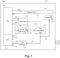
- Fig. 1 a partial view of an embodiment of a system in accordance with the disclosure is shown in Fig. 1 and is designated generally by reference character 100.
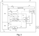
- Other embodiments of systems in accordance with the disclosure, or aspects thereof, are provided in Figs. 2-3 , as will be described.
- the systems and methods described herein can be used to provide fuel flow and rotational drive for starting a gas turbine engine, to provide for low speed motoring of the engine after shut down, and to provide for fuel flow and potentially electrical power generation during normal operation.
- the system 100 includes a main pump 102 having a main pump shaft 104 connected to a gear box 106 for driving the main pump 102 with rotational power from the gear box 106 in a run mode shown in Figs. 2 and 3 , and for driving the gear box 106 with rotational power from the main pump 102 in a start mode shown in Fig. 1 .
- the main pump 102 can be a positive displacement pump, e.g. vane, gear, piston, gerotor, or the like.
- the system 100 includes a first fuel line 108 with an inlet 110 configured to be connected in fluid communication with a fuel source, e.g. an aircraft fuel tank connected to the fuel oil manifold (FOM) 112.
- the first fuel line 108 includes a first branch 114 in fluid communication with the main pump 102, and a second branch 116.
- a start pump 118 is connected in fluid communication with the second branch 116 of the first fuel line 108.
- the start pump 118 is a positive displacement pump.
- a second fuel line 120 connects the start pump 118 in fluid communication with a pump management valve (PMV) 122.
- a third fuel line 124 connects the main pump 102 in fluid communication with the pump management valve 122.
- the PMV 122 is connected in fluid communication with the second fuel line 120, with the third fuel line 124, and with a fourth fuel line 126.
- the fourth fuel line 126 has an outlet 128 configured to be connected to supply a downstream fuel system, i.e. to the FOM 112.
- the PMV 122 has a first state connecting the second fuel line 120 in fluid communication with the third fuel line 124 in the start mode to drive the main pump 102 with flow pressurized by the start pump 118.
- This state of the PMV also allows flow from the start pump 118 to the fourth fuel line 126 to supply the fuel metering system or component 129 in the fourth fuel line 126 with fuel pressurized by the start pump 118 for use by the engine during engine startup.
- the fuel metering component 129 is included in the fourth line 126, configured to meter flow from the outlet 128 of the fourth line 126 to the FOM 112 in the run and start modes.
- a second state of the PMV 122 connects the third fuel line 124 in fluid communication with the fourth fuel line 126 for supplying fuel from the main pump 102 to the outlet 128 of the fourth fuel line 126 to supply the downstream fuel system including the FOM 112 and gas generators of a gas turbine engine in the run mode, i.e. after starting of the engine.
- the PMV 122 connects the second and third lines 120, 124 in limited fluid communication to flow a limited amount of fuel through the start pump 118, i.e. in reverse flow from the start mode in Fig. 1 , for cooling the start pump 119.
- Start pump cooling may be required to manage the temperature of the start pump and corresponding fluid passages, which are likely to be located in the hot engine bay. Negative impacts of high temperatures can include reduced electronics life and unwanted carbon deposits. For purposes of this disclosure, this aspect of the system can be present or not, depending on the application.
- the PMV 122 connects the second and third fuel lines 120, 124 in fluid communication to supply the FOM 112 as in the run mode of Fig. 2 , and can connect a the fuel metering component 129 to the start pump 118 through a fifth line 130.
- the fifth line 130 connects the fuel metering component 129 to the start pump 118 to bypass flow in the from the main pump 102 back to the inlet of the main pump 102 in the first line 108 through the start pump 118.
- the fifth line 130 is a regeneration fuel line that connects the fuel metering component 129 in fluid communication with the start pump 118 in the regeneration sub-mode to supply fuel flow to the start pump 118
- This bypass flow accommodates high engine speeds acting on the fixed displacement main pump 102 and can drive the start pump 102 for electrical energy recovery by using the start pump 102 to drive an electric machine 132 for electric power generation, but the bypass for electrical regeneration can apply even if a non-fixed displacement pump is used for the main pump 102
- the system 100 can include the gear box 106, wherein the main pump shaft 104 is connected to drive the gear box 106 in the start mode of Fig. 1 , and wherein the gear box 106 is connected to drive the main pump shaft 104 for fuel pumping in the run modes of Figs. 2-3 .
- the gear box 106 is connected to drive an engine shaft 140, e.g. an engine N2 shaft, i.e. the high speed shaft of the engine, in the start mode of Fig. 1 , and to be driven by the engine shaft 140 in the run mode of Figs. 2-3 .
- the system can include the FOM 112 connected in fluid communication to receive fuel supplied from the fourth line 126.
- a solenoid 133 in the IFPC 138 can be connected to supply in a sixth line 136 selectively connecting the PMV 122 in fluid communication with the FOM 112, bypassing the fuel metering component 129.
- the solenoid 133 can provide a way for the aircraft to control the PMV 122. Typical implementations require supplying a high and low pressure to the solenoid 133, which then translated an electrical command from the electronic engine controller into a hydraulic command that is sent to the valve.
- the solenoid 133 is shown de-energized and the PMV 122 is in run mode. This polarity could be swapped.
- the high pressure side is shown connected downstream of the PMV 122 to show that it is connected to the highest pressure source regardless of engine state (main or start driving).
- the main pump, its shaft 104, the start pump 118 and its motor/generator 132, the PMV 122, the fuel metering component 129, the solenoid 134, and the fuel lines 108, 120, 124, 126, 130, 139, 136 can all be housed in a line replaceable unit (LRU), i.e. an integrated fuel pump and control (IFPC) 138.
- LRU line replaceable unit
- IFPC integrated fuel pump and control
- the electric machine 132 is a motor/generator that is configured to drive the start pump 118 in the start mode of Fig. 1 , and to be driven by the start pump 118 in the run mode, specifically the regeneration sub-mode shown in Fig. 3 , for generating electrical power from bypass flow of the main pump 102.
- a controller 142 can be connected for active control of the PMV 122, the solenoid 134, and the and the electric machine 132 for changing between the start mode of Fig. 1 , the run mode of Fig. 2 , and the regeneration sub-mode of the run mode in Fig. 3 .
- a method includes providing pressurized fuel from a start pump (e.g. start pump 118) to a main pump (e.g. main pump 102) to drive the main pump, and using the main pump to drive a gear box (e.g. gear box 106) for starting a gas turbine engine.
- the method includes after starting the gas turbine engine, using the main pump to supply fuel to the gas turbine engine. Switching between start mode and run mode can occur when the N2 shaft speed of the engine is 45% of its top speed.
- Providing pressurized fuel from the start pump includes driving the start pump with an electric motor (e.g. electric machine 132).
- the method includes supplying fuel from the start pump to the gas turbine engine during start up as shown in Fig. 1 .
- the method includes flowing fuel from the main pump through the start pump after starting the gas turbine engine for cooling the start pump as shown in Fig. 2 .
- the method includes driving the start pump with flow from the main pump, and using the start pump to drive an electric machine to generate electrical power after starting the gas turbine engine, as shown in Fig. 3 .
- the method includes after shutting down the engine, driving flow through the main pump with flow pressurized by the start pump to motor the gas turbine engine for uniform cooling of the gas turbine engine. This mode can follow the same flow scheme as shown in Fig.
- Variable rotation rates can be achieved hydraulically while starting the gas turbine engine and after starting the gas turbine engine by modulating a pump management valve (e.g. PMV 122) connected in fluid communication with the main pump and with the start pump, and/or electrically by using a variable speed electric motor drive to control the start pump.
- a pump management valve e.g. PMV 122
- Systems and methods as disclosed herein provide potential benefits including the following.
- The provide for dual use of an electric start pump. They provide dual use of the main fuel pump. They enable slow motoring of the engine shaft. They allow for replacement of pneumatic engine starting systems and the associated components. They allow energy recapture from waste fuel flow.
Landscapes
- Engineering & Computer Science (AREA)
- Chemical & Material Sciences (AREA)
- Combustion & Propulsion (AREA)
- Mechanical Engineering (AREA)
- General Engineering & Computer Science (AREA)
- Output Control And Ontrol Of Special Type Engine (AREA)
Abstract
A system includes a main pump (102) having a main pump shaft (104) configured to connect to a gear box (106) for driving the main pump with rotational power from the gear box in a run mode, and for driving the gear box with rotational power from the main pump in a start mode. The system includes a first fuel line (108) with an inlet (110) configured to connect to connected in fluid communication with a fuel source. The first fuel line includes a first branch (114) in fluid communication with the main pump, and a second branch (116). A start pump (118) is connected in fluid communication with the second branch of the first fuel line. A second fuel line (120) connects the start pump in fluid communication with a pump management valve (PMV) (122). A third fuel line (124) connects the main pump in fluid communication with the pump management valve.
Description
- The present disclosure relates to fuel systems, and more particularly to main fuel pump operation in gas turbine engines.
- Large commercial gas turbine engines require dedicated air turbine starting (ATS) systems. When an engine is stationary after being operated at high temperature, convention currents can cause unequal temperatures throughout the cross-section of the engine core. Motoring the air turbine starter (ATS) can be used to rotate the engine, driver airflow, and equalize temperatures radially. However, ATS systems generally do not have fine speed control at low rotor speeds.
- The conventional techniques have been considered satisfactory for their intended purpose. However, there is an ever present need for improved systems and methods for starting, operating, and motoring gas turbine engines for even cooling after operation. This disclosure provides a solution for this need.
- A system includes a main pump having a main pump shaft configured to connect to a gear box for driving the main pump with rotational power from the gear box in a run mode, and for driving the gear box with rotational power from the main pump in a start mode. The system includes a first fuel line with an inlet configured to be connected in fluid communication with a fuel source. The first fuel line includes a first branch in fluid communication with the main pump, and a second branch. A start pump is connected in fluid communication with the second branch of the first fuel line. A second fuel line connects the start pump in fluid communication with a pump management valve (PMV). A third fuel line connects the main pump in fluid communication with the pump management valve.
- The PMV can be connected in fluid communication with the second fuel line, with the third fuel line, and with a fourth fuel line. The fourth fuel line can have an outlet configured to be connected to supply a downstream fuel system. The PMV can have a first state connecting the second fuel line in fluid communication with the third fuel line in the start mode to drive the main pump with flow pressurized by the start pump. A second state of the PMV can connect the third fuel line in fluid communication with the fourth fuel line for supplying fuel from the main pump to the outlet of the fourth fuel line in the run mode.
- In the run mode, the PMV can connect the third and fourth fuel lines in fluid communication to bypass flow in the from the main pump back to the main pump through the fifth line and through the start pump, for electrical energy recovery by using the start pump to drive an electric machine for electric power generation.
- A fuel metering component can be included in the fourth line, configured to meter flow from the outlet of the fourth line in the run and start modes. A regeneration fuel line can connect the fuel metering component in fluid communication with the start pump in the regeneration sub-mode to supply fuel flow to the start pump.
- The system can include the gear box, wherein the main pump shaft is connected to drive the gear box in the start mode, and wherein the gear box is connected to drive the main pump shaft for fuel pumping in the run mode. The gear box can be connected to drive an engine shaft in the start mode, and to be driven by the engine shaft in the run mode. A fuel oil manifold (FOM) can be connected in fluid communication to receive fuel supplied from the fourth line. A solenoid in a fifth line can selectively connect the PMV in fluid communication with the FOM, bypassing the fuel metering component.
- The main pump can be a positive displacement pump. The start pump can be a positive displacement pump. An electric machine can be configured to drive the start pump in the start mode. The electric machine can be configured to be driven by the start pump in the run mode for generating electrical power from bypass flow of the main pump. A controller can be connected for active control of the PMV and the electrical motor for changing between the start mode and the run mode.
- A method includes providing pressurized fuel from a start pump to a main pump to drive the main pump, and using the main pump to drive a gear box for starting a gas turbine engine. The method includes after starting the gas turbine engine, using the main pump to supply fuel to the gas turbine engine.
- Providing pressurized fuel from the start pump can include driving the start pump with an electric motor. The method can include supplying fuel from the start pump to the gas turbine engine during start up. The method can include flowing fuel from the main pump through the start pump after starting the gas turbine engine for cooling the start pump. The method can include driving the start pump with flow from the main pump, and using the start pump to drive an electric machine to generate electrical power after starting the gas turbine engine. The method can include after shutting down the engine, driving flow through the main pump with flow pressurized by the start pump to motor the gas turbine engine for uniform cooling of the gas turbine engine.
- These and other features of the systems and methods of the subject disclosure will become more readily apparent to those skilled in the art from the following detailed description of the preferred embodiments taken in conjunction with the drawings.
- So that those skilled in the art to which the subject disclosure appertains will readily understand how to make and use the devices and methods of the subject disclosure without undue experimentation, preferred embodiments thereof will be described in detail herein below with reference to certain figures, wherein:
-
Fig. 1 is a schematic view of an embodiment of a system constructed in accordance with the present disclosure, showing the system in start mode; -
Fig. 2 is a schematic view of the system ofFig. 1 , showing the system in run mode; and -
Fig. 3 is a schematic view of the system ofFig. 1 , showing the system in a regeneration sub-mode of the run mode. - Reference will now be made to the drawings wherein like reference numerals identify similar structural features or aspects of the subject disclosure. For purposes of explanation and illustration, and not limitation, a partial view of an embodiment of a system in accordance with the disclosure is shown in
Fig. 1 and is designated generally byreference character 100. Other embodiments of systems in accordance with the disclosure, or aspects thereof, are provided inFigs. 2-3 , as will be described. The systems and methods described herein can be used to provide fuel flow and rotational drive for starting a gas turbine engine, to provide for low speed motoring of the engine after shut down, and to provide for fuel flow and potentially electrical power generation during normal operation. - Large commercial aero engines require traditionally dedicated air turbine starting systems. Such systems generally do not have fine speed control at low rotor speeds. Systems and methods disclosed herein can utilize fueldraulics to rotate the engine N2 shaft instead of pneumatics to enable slow/variable speed motoring, start, and bypass electrical energy recovery.
- The
system 100 includes amain pump 102 having amain pump shaft 104 connected to agear box 106 for driving themain pump 102 with rotational power from thegear box 106 in a run mode shown inFigs. 2 and3 , and for driving thegear box 106 with rotational power from themain pump 102 in a start mode shown inFig. 1 . Themain pump 102 can be a positive displacement pump, e.g. vane, gear, piston, gerotor, or the like. - The
system 100 includes a first fuel line 108 with aninlet 110 configured to be connected in fluid communication with a fuel source, e.g. an aircraft fuel tank connected to the fuel oil manifold (FOM) 112. The first fuel line 108 includes afirst branch 114 in fluid communication with themain pump 102, and asecond branch 116. Astart pump 118 is connected in fluid communication with thesecond branch 116 of the first fuel line 108. Thestart pump 118 is a positive displacement pump. Asecond fuel line 120 connects thestart pump 118 in fluid communication with a pump management valve (PMV) 122. Athird fuel line 124 connects themain pump 102 in fluid communication with thepump management valve 122. The PMV 122 is connected in fluid communication with thesecond fuel line 120, with thethird fuel line 124, and with afourth fuel line 126. Thefourth fuel line 126 has anoutlet 128 configured to be connected to supply a downstream fuel system, i.e. to theFOM 112. - As shown in
Fig. 1 , thePMV 122 has a first state connecting thesecond fuel line 120 in fluid communication with thethird fuel line 124 in the start mode to drive themain pump 102 with flow pressurized by thestart pump 118. This state of the PMV also allows flow from thestart pump 118 to thefourth fuel line 126 to supply the fuel metering system orcomponent 129 in thefourth fuel line 126 with fuel pressurized by thestart pump 118 for use by the engine during engine startup. Thefuel metering component 129 is included in thefourth line 126, configured to meter flow from theoutlet 128 of thefourth line 126 to theFOM 112 in the run and start modes. - As shown in
Fig. 2 , a second state of thePMV 122 connects thethird fuel line 124 in fluid communication with thefourth fuel line 126 for supplying fuel from themain pump 102 to theoutlet 128 of thefourth fuel line 126 to supply the downstream fuel system including theFOM 112 and gas generators of a gas turbine engine in the run mode, i.e. after starting of the engine. In the run mode, thePMV 122 connects the second andthird lines start pump 118, i.e. in reverse flow from the start mode inFig. 1 , for cooling the start pump 119. Start pump cooling may be required to manage the temperature of the start pump and corresponding fluid passages, which are likely to be located in the hot engine bay. Negative impacts of high temperatures can include reduced electronics life and unwanted carbon deposits. For purposes of this disclosure, this aspect of the system can be present or not, depending on the application. - With reference now to
Fig. 3 , in a regeneration sub-mode of the run mode e.g. at high engine speeds such as when an aircraft is cruising, thePMV 122 connects the second andthird fuel lines FOM 112 as in the run mode ofFig. 2 , and can connect a thefuel metering component 129 to thestart pump 118 through afifth line 130. Thefifth line 130 connects thefuel metering component 129 to thestart pump 118 to bypass flow in the from themain pump 102 back to the inlet of themain pump 102 in the first line 108 through thestart pump 118. Thefifth line 130 is a regeneration fuel line that connects thefuel metering component 129 in fluid communication with thestart pump 118 in the regeneration sub-mode to supply fuel flow to thestart pump 118 This bypass flow accommodates high engine speeds acting on the fixed displacementmain pump 102 and can drive thestart pump 102 for electrical energy recovery by using thestart pump 102 to drive anelectric machine 132 for electric power generation, but the bypass for electrical regeneration can apply even if a non-fixed displacement pump is used for themain pump 102 - The
system 100 can include thegear box 106, wherein themain pump shaft 104 is connected to drive thegear box 106 in the start mode ofFig. 1 , and wherein thegear box 106 is connected to drive themain pump shaft 104 for fuel pumping in the run modes ofFigs. 2-3 . Thegear box 106 is connected to drive anengine shaft 140, e.g. an engine N2 shaft, i.e. the high speed shaft of the engine, in the start mode ofFig. 1 , and to be driven by theengine shaft 140 in the run mode ofFigs. 2-3 . The system can include theFOM 112 connected in fluid communication to receive fuel supplied from thefourth line 126. A solenoid 133 in theIFPC 138 can be connected to supply in asixth line 136 selectively connecting thePMV 122 in fluid communication with theFOM 112, bypassing thefuel metering component 129. The solenoid 133 can provide a way for the aircraft to control thePMV 122. Typical implementations require supplying a high and low pressure to the solenoid 133, which then translated an electrical command from the electronic engine controller into a hydraulic command that is sent to the valve. InFig. 1 , the solenoid 133 is shown de-energized and thePMV 122 is in run mode. This polarity could be swapped. The high pressure side is shown connected downstream of thePMV 122 to show that it is connected to the highest pressure source regardless of engine state (main or start driving). The main pump, itsshaft 104, thestart pump 118 and its motor/generator 132, thePMV 122, thefuel metering component 129, thesolenoid 134, and thefuel lines - The
electric machine 132 is a motor/generator that is configured to drive thestart pump 118 in the start mode ofFig. 1 , and to be driven by thestart pump 118 in the run mode, specifically the regeneration sub-mode shown inFig. 3 , for generating electrical power from bypass flow of themain pump 102. Acontroller 142 can be connected for active control of thePMV 122, thesolenoid 134, and the and theelectric machine 132 for changing between the start mode ofFig. 1 , the run mode ofFig. 2 , and the regeneration sub-mode of the run mode inFig. 3 . - With continued reference to
Figs. 1-3 , a method includes providing pressurized fuel from a start pump (e.g. start pump 118) to a main pump (e.g. main pump 102) to drive the main pump, and using the main pump to drive a gear box (e.g. gear box 106) for starting a gas turbine engine. The method includes after starting the gas turbine engine, using the main pump to supply fuel to the gas turbine engine. Switching between start mode and run mode can occur when the N2 shaft speed of the engine is 45% of its top speed. - Providing pressurized fuel from the start pump includes driving the start pump with an electric motor (e.g. electric machine 132). The method includes supplying fuel from the start pump to the gas turbine engine during start up as shown in
Fig. 1 . The method includes flowing fuel from the main pump through the start pump after starting the gas turbine engine for cooling the start pump as shown inFig. 2 . The method includes driving the start pump with flow from the main pump, and using the start pump to drive an electric machine to generate electrical power after starting the gas turbine engine, as shown inFig. 3 . The method includes after shutting down the engine, driving flow through the main pump with flow pressurized by the start pump to motor the gas turbine engine for uniform cooling of the gas turbine engine. This mode can follow the same flow scheme as shown inFig. 1 for startup, but can be done without burning fuel in the gas generator of the gas turbine engine. Variable rotation rates can be achieved hydraulically while starting the gas turbine engine and after starting the gas turbine engine by modulating a pump management valve (e.g. PMV 122) connected in fluid communication with the main pump and with the start pump, and/or electrically by using a variable speed electric motor drive to control the start pump. - Systems and methods as disclosed herein provide potential benefits including the following. The provide for dual use of an electric start pump. They provide dual use of the main fuel pump. They enable slow motoring of the engine shaft. They allow for replacement of pneumatic engine starting systems and the associated components. They allow energy recapture from waste fuel flow.
- The methods and systems of the present disclosure, as described above and shown in the drawings, provide for fuel flow and rotational drive for starting a gas turbine engine, provide for low speed motoring of the engine after shut down, and provide for fuel flow and potentially electrical power generation during normal operation. While the apparatus and methods of the subject disclosure have been shown and described with reference to preferred embodiments, those skilled in the art will readily appreciate that changes and/or modifications may be made thereto without departing from the scope of the invention as defined by the claims.
Claims (15)
- A system comprising:a main pump (102) having a main pump shaft (104) configured to connect to a gear box (106) for driving the main pump with rotational power from the gear box in a run mode, and for driving the gear box with rotational power from the main pump in a start mode;a first fuel line (108) with an inlet (110) configured to be connected in fluid communication with a fuel source, wherein the first fuel line includes a first branch (114) in fluid communication with the main pump, and a second branch (116);a start pump (118) connected in fluid communication with the second branch of the first fuel line;a second fuel line (120) connecting the start pump in fluid communication with a pump management valve, PMV (122); anda third fuel line (124) connecting the main pump in fluid communication with the pump management valve.
- The system as recited in claim 1, wherein the PMV is connected in fluid communication with the second fuel line, with the third fuel line, and with a fourth fuel line (126), wherein the fourth fuel line has an outlet (128) configured to be connected to supply a downstream fuel system, wherein the PMV has a first state connecting the second fuel line in fluid communication with the third fuel line in the start mode to drive the main pump with flow pressurized by the start pump, and a second state connecting the third fuel line in fluid communication with the fourth fuel line for supplying fuel from the main pump to the outlet of the fourth fuel line in the run mode.
- The system as recited in claim 2, wherein in the run mode, the PMV connects the second and third lines in limited fluid communication to flow a limited amount of fuel through the start pump for cooling.
- The system as recited in claim 2, wherein in a regeneration sub-mode of the run mode, the PMV connects the third and fourth fuel lines in fluid communication to bypass flow from the main pump back to the main pump through the fifth line and through the start pump, for electrical energy recovery by using the start pump to drive an electric machine for electric power generation.
- The system as recited in claim 4, further comprising a fuel metering component (129) in the fourth line, configured to meter flow from the outlet of the fourth line in the run and start modes, and wherein a regeneration fuel line connects the fuel metering component in fluid communication with the start pump in the regeneration sub-mode to supply fuel flow to the start pump.
- The system as recited in any preceding claim, further comprising the gear box (106), wherein the main pump shaft is connected to drive the gear box in the start mode, and wherein the gear box is connected to drive the main pump shaft for fuel pumping in the run mode.
- The system as recited in claim 6, wherein the gear box is connected to drive an engine shaft (140) in the start mode, and to be driven by the engine shaft in the run mode.
- The system as recited in claim 7, further comprising a fuel oil manifold, FOM, (112) connected in fluid communication to receive fuel supplied from the fourth line.
- The system as recited in claim 8, further comprising a solenoid in a fifth line (130) selectively connecting the PMV in fluid communication with the FOM, bypassing a fuel metering component.
- The system as recited in any preceding claim, wherein the main pump is a positive displacement pump, and/or wherein the start pump is a positive displacement pump.
- The system as recited in any preceding claim, further comprising an electric machine (132) configured to drive the start pump in the start mode, and optionally wherein the electric machine is configured to be driven by the start pump in the run mode for generating electrical power from bypass flow of the main pump, and further optionally further comprising a controller (142) connected for active control of the PMV and the electrical motor for changing between the start mode and the run mode.
- A method comprising:providing pressurized fuel from a start pump (118) to a main pump (102) to drive the main pump, and using the main pump to drive a gear box (106) for starting a gas turbine engine; andafter starting the gas turbine engine, using the main pump to supply fuel to the gas turbine engine.
- The method as recited in claim 12, wherein providing pressurized fuel from the start pump includes driving the start pump with an electric motor (132), or further comprising driving the start pump with flow from the main pump, and using the start pump to drive an electric machine to generate electrical power after starting the gas turbine engine
- The method as recited in claim 12, further comprising supplying fuel from the start pump to the gas turbine engine during start up and/or further comprising flowing fuel from the main pump through the start pump after starting the gas turbine engine for cooling the start pump.
- The method as recited in claim 12, 13 or 14, further comprising after shutting down the engine, driving flow through the main pump with flow pressurized by the start pump to motor the gas turbine engine for uniform cooling of the gas turbine engine.
Applications Claiming Priority (1)
| Application Number | Priority Date | Filing Date | Title |
|---|---|---|---|
| US18/230,805 US12253029B2 (en) | 2023-08-07 | 2023-08-07 | Fuel system for dual use gas turbine engine main fuel pump |
Publications (1)
| Publication Number | Publication Date |
|---|---|
| EP4513021A1 true EP4513021A1 (en) | 2025-02-26 |
Family
ID=92258725
Family Applications (1)
| Application Number | Title | Priority Date | Filing Date |
|---|---|---|---|
| EP24193114.6A Pending EP4513021A1 (en) | 2023-08-07 | 2024-08-06 | Fuel system for dual use gas turbine engine main fuel pump |
Country Status (2)
| Country | Link |
|---|---|
| US (1) | US12253029B2 (en) |
| EP (1) | EP4513021A1 (en) |
Citations (3)
| Publication number | Priority date | Publication date | Assignee | Title |
|---|---|---|---|---|
| US5159808A (en) * | 1990-07-09 | 1992-11-03 | General Electric Company | Gas turbine engine fuel and hydraulic fluid pumping system |
| JP5941744B2 (en) * | 2012-04-27 | 2016-06-29 | 株式会社Ihiエアロスペース | Power generation system |
| US20180283281A1 (en) * | 2017-03-31 | 2018-10-04 | Hamilton Sundstrand Corporation | Accessory gearboxes |
Family Cites Families (21)
| Publication number | Priority date | Publication date | Assignee | Title |
|---|---|---|---|---|
| FR2742805B1 (en) * | 1995-12-20 | 1998-01-16 | Snecma | ENGINE RESTART ASSISTANCE SYSTEM AFTER TOTAL LOSS OF MOTORIZATION |
| US7805947B2 (en) * | 2005-05-19 | 2010-10-05 | Djamal Moulebhar | Aircraft with disengageable engine and auxiliary power unit components |
| US8127548B2 (en) * | 2008-02-21 | 2012-03-06 | Honeywell International Inc. | Hybrid electrical/mechanical turbine engine fuel supply system |
| US7690344B2 (en) | 2008-07-24 | 2010-04-06 | Gm Global Technology Operations, Inc. | Method and apparatus for supporting stop-and-go engine functionality |
| FR2934321B1 (en) * | 2008-07-25 | 2013-09-27 | Hispano Suiza Sa | CONTROL OF FUEL FLOW DRAINED IN A FUEL SYSTEM OF AN AIRCRAFT PROPELLED BY AN ENGINE. |
| US8302406B2 (en) | 2008-10-15 | 2012-11-06 | Woodward, Inc. | Fuel delivery and control system including a positive displacement actuation pump with a variable pressure regulator supplementing a fixed displacement main fuel pump |
| US8286432B2 (en) * | 2008-11-25 | 2012-10-16 | Honeywell International Inc. | Electric power generating turbine engine fuel supply system |
| GB201102772D0 (en) | 2011-02-17 | 2011-03-30 | Rolls Royce Goodrich Engine Control Systems Ltd | Pumping arrangement |
| EP3008311A4 (en) * | 2013-06-12 | 2016-07-20 | United Technologies Corp | Fuel/oil manifold |
| US10513983B2 (en) * | 2013-09-27 | 2019-12-24 | United Technologies Corporation | Fuel/oil manifold |
| US9885287B2 (en) * | 2014-09-11 | 2018-02-06 | Honeywell International Inc. | Gas turbine engine mechanical-electrical hybrid fuel delivery system |
| US10100744B2 (en) * | 2015-06-19 | 2018-10-16 | The Boeing Company | Aircraft bleed air and engine starter systems and related methods |
| US10125628B2 (en) * | 2017-04-13 | 2018-11-13 | General Electric Company | Systems and methods for power generation synchronous condensing |
| FR3078551B1 (en) | 2018-03-05 | 2020-02-28 | Safran Aircraft Engines | ANTICIPATIVE CONTROL OF A FUEL SUPPLY CIRCUIT OF A TURBOMACHINE |
| US11174793B2 (en) * | 2018-09-19 | 2021-11-16 | Raytheon Technologies Corporation | Hydraulic starter assembly for a gas turbine engine |
| US11060461B2 (en) * | 2018-12-13 | 2021-07-13 | Hamilton Sundstrand Corporation | Fuel systems having reduced bypass flow |
| US20210079848A1 (en) * | 2019-03-20 | 2021-03-18 | United Technologies Corporation | Secondary fuel flow demand fuel pumping system |
| US20200300168A1 (en) | 2019-03-20 | 2020-09-24 | United Technologies Corporation | Backup system for demand fuel pumping system |
| US20210102517A1 (en) | 2019-10-04 | 2021-04-08 | Hamilton Sundstrand Corporation | Electric pump assisted fuel system |
| US11629652B2 (en) | 2020-02-05 | 2023-04-18 | Hamilton Sundstrand Corporation | Metering pump system |
| US11702990B2 (en) * | 2021-09-08 | 2023-07-18 | Rolls-Royce North American Technologies Inc. | Redundant electrically driven fuel and oil pumping system for gas turbine with bidirectional pump motor |
-
2023
- 2023-08-07 US US18/230,805 patent/US12253029B2/en active Active
-
2024
- 2024-08-06 EP EP24193114.6A patent/EP4513021A1/en active Pending
Patent Citations (3)
| Publication number | Priority date | Publication date | Assignee | Title |
|---|---|---|---|---|
| US5159808A (en) * | 1990-07-09 | 1992-11-03 | General Electric Company | Gas turbine engine fuel and hydraulic fluid pumping system |
| JP5941744B2 (en) * | 2012-04-27 | 2016-06-29 | 株式会社Ihiエアロスペース | Power generation system |
| US20180283281A1 (en) * | 2017-03-31 | 2018-10-04 | Hamilton Sundstrand Corporation | Accessory gearboxes |
Also Published As
| Publication number | Publication date |
|---|---|
| US20250052199A1 (en) | 2025-02-13 |
| US12253029B2 (en) | 2025-03-18 |
Similar Documents
| Publication | Publication Date | Title |
|---|---|---|
| JP5142206B2 (en) | Apparatus for generating electrical power in a two-spool gas turbine engine | |
| CA2643489C (en) | Gas turbine engine oil system operation | |
| EP2987961B1 (en) | Gas turbine engine system and corresponding method | |
| EP3726012B1 (en) | Gas turbine engine generator oil pump | |
| US9885288B2 (en) | Anti-windmilling starter generator | |
| JP2015514895A (en) | Turbo assist | |
| WO2007147229A1 (en) | Apparatus and method for controlling engine windmilling | |
| US11761378B2 (en) | Bleed air charged cooling system with turbo-generator | |
| RU2006117061A (en) | METHOD AND SYSTEM OF POWER GENERATION FOR DRIVING AUXILIARY UNITS OF ENGINE | |
| US20110133545A1 (en) | Aircraft electrical power system architecture using auxiliary power unit during approach and taxi | |
| WO2009137478A1 (en) | Multi-spool intercooled recuperated gas turbine | |
| US7871248B2 (en) | Airframe mounted electric motor driven lubrication pump control deoil system | |
| EP3712406B1 (en) | Backup system for demand fuel pumping system | |
| US20230417178A1 (en) | Hybrid-electric single engine descent failure management | |
| JP2024540969A (en) | Hybrid Propulsion System | |
| KR101814878B1 (en) | Ship propulsion system and method of operation of ship and ship propulsion system | |
| US12253029B2 (en) | Fuel system for dual use gas turbine engine main fuel pump | |
| KR20200112117A (en) | A Electric Power System Of HEV | |
| JP4922110B2 (en) | Power generator | |
| CN115126604B (en) | Turbine engine system with fuel deoxygenation system and turbine electric system | |
| US20220349317A1 (en) | Flow recirculative power system | |
| CN111322150B (en) | Turbo compound system | |
| JPH11107311A (en) | Power generator of construction machine | |
| RU2211347C1 (en) | Fuel feed system of flying vehicle turbojet engine | |
| US12338773B2 (en) | Gas turbine engine having a compressor, combustor and turbine aligned along a rotating shaft |
Legal Events
| Date | Code | Title | Description |
|---|---|---|---|
| PUAI | Public reference made under article 153(3) epc to a published international application that has entered the european phase |
Free format text: ORIGINAL CODE: 0009012 |
|
| STAA | Information on the status of an ep patent application or granted ep patent |
Free format text: STATUS: THE APPLICATION HAS BEEN PUBLISHED |
|
| AK | Designated contracting states |
Kind code of ref document: A1 Designated state(s): AL AT BE BG CH CY CZ DE DK EE ES FI FR GB GR HR HU IE IS IT LI LT LU LV MC ME MK MT NL NO PL PT RO RS SE SI SK SM TR |
|
| STAA | Information on the status of an ep patent application or granted ep patent |
Free format text: STATUS: REQUEST FOR EXAMINATION WAS MADE |
|
| 17P | Request for examination filed |
Effective date: 20250826 |