EP4512974A1 - A roof window arrangement comprising a common stationary frame and at least a first window unit and a second window unit - Google Patents
A roof window arrangement comprising a common stationary frame and at least a first window unit and a second window unit Download PDFInfo
- Publication number
- EP4512974A1 EP4512974A1 EP24195360.3A EP24195360A EP4512974A1 EP 4512974 A1 EP4512974 A1 EP 4512974A1 EP 24195360 A EP24195360 A EP 24195360A EP 4512974 A1 EP4512974 A1 EP 4512974A1
- Authority
- EP
- European Patent Office
- Prior art keywords
- window
- window unit
- operational condition
- mullion
- roof
- Prior art date
- Legal status (The legal status is an assumption and is not a legal conclusion. Google has not performed a legal analysis and makes no representation as to the accuracy of the status listed.)
- Pending
Links
Images


Classifications
-
- E—FIXED CONSTRUCTIONS
- E04—BUILDING
- E04D—ROOF COVERINGS; SKY-LIGHTS; GUTTERS; ROOF-WORKING TOOLS
- E04D13/00—Special arrangements or devices in connection with roof coverings; Protection against birds; Roof drainage ; Sky-lights
- E04D13/03—Sky-lights; Domes; Ventilating sky-lights
- E04D13/035—Sky-lights; Domes; Ventilating sky-lights characterised by having movable parts
- E04D13/0351—Sky-lights; Domes; Ventilating sky-lights characterised by having movable parts the parts pivoting about a fixed axis
- E04D13/0354—Sky-lights; Domes; Ventilating sky-lights characterised by having movable parts the parts pivoting about a fixed axis the parts being flat
-
- E—FIXED CONSTRUCTIONS
- E04—BUILDING
- E04D—ROOF COVERINGS; SKY-LIGHTS; GUTTERS; ROOF-WORKING TOOLS
- E04D13/00—Special arrangements or devices in connection with roof coverings; Protection against birds; Roof drainage ; Sky-lights
- E04D13/03—Sky-lights; Domes; Ventilating sky-lights
- E04D13/035—Sky-lights; Domes; Ventilating sky-lights characterised by having movable parts
- E04D13/0357—Sky-lights; Domes; Ventilating sky-lights characterised by having movable parts the parts pivoting about an axis supported on a hinged frame or arms
-
- E—FIXED CONSTRUCTIONS
- E06—DOORS, WINDOWS, SHUTTERS, OR ROLLER BLINDS IN GENERAL; LADDERS
- E06B—FIXED OR MOVABLE CLOSURES FOR OPENINGS IN BUILDINGS, VEHICLES, FENCES OR LIKE ENCLOSURES IN GENERAL, e.g. DOORS, WINDOWS, BLINDS, GATES
- E06B3/00—Window sashes, door leaves, or like elements for closing wall or like openings; Layout of fixed or moving closures, e.g. windows in wall or like openings; Features of rigidly-mounted outer frames relating to the mounting of wing frames
- E06B3/32—Arrangements of wings characterised by the manner of movement; Arrangements of movable wings in openings; Features of wings or frames relating solely to the manner of movement of the wing
- E06B3/50—Arrangements of wings characterised by the manner of movement; Arrangements of movable wings in openings; Features of wings or frames relating solely to the manner of movement of the wing with more than one kind of movement
Definitions
- the present invention relates to a roof window arrangement
- a roof window arrangement comprising a common stationary frame configured to be built into a roof surface, the common stationary frame having a top frame member and a bottom frame member extending in a width direction, and two side frame members extending in a height direction, the roof window arrangement further comprising at least a first window unit and a second window unit configured in a side-by-side configuration where each window unit comprises a pane-carrying sash, with a top sash member, a bottom sash member and two side sash members.
- Roof windows to be installed in inclined roof surfaces come in a variety of types, and are either installed as stand-alone window units, in which all sides of the roof window borders on the roofing, or in roof window arrangements where several window units are built together to combine into larger arrays providing a larger light influx into a room of a building, and in which only outer sides of the outermost window units border on the surrounding roofing.
- Configurations of twin or quadruple roof window arrangements installed side-by-side and/or above each other, respectively, are shown and described in Applicant's published international application WO 2004/055291 A1 .
- a roof window arrangement with two rows of each three window units are connected to a respective frame structure installed in the roof structure.
- the frame structure usually comprises a common frame encompassing all the individual window units and the window units are typically separated by structural elements such as mullions which are fixed to the frame structure to allow some or all window units to be opened individually.
- the mullions provide stability and a place to arrange hinges for the window units, however the large aperture created by removal of the rafter(s) is not fully utilised because the mullions divide the aperture into several small openings. So even though the prior art window arrangements function well, they do not utilize the aperture in the roof structure optimally.
- a roof window arrangement of the kind mentioned in the introduction which is furthermore characterised in that at least one of the window units has an openable pane-carrying sash which opens about a horizontal centre hinge axis defined by a set of hinges arranged substantially at the centre of the window units in the height direction in a first operational condition, and where the at least first window unit and second window unit are configured to open as a common openable sash in a second operational condition.
- the roof window arrangement with window units arranged in a side-by-side configuration can be individually operated in the first operational condition and the window units of roof window arrangement can open as a single window unit in the second operational condition.
- One advantage of the second operational condition is that the roof window arrangement functions better as a fire escape.
- the roof window arrangement provides a better utilization of the aperture created to accommodate the roof window arrangement in the roof surface.
- Top hung is here to be understood as being openable about a horizontal axis extending in the width direction in proximity to the top frame member.
- each of the window units has an openable pane-carrying sash which opens about the centre hinge axis.
- at least the second window unit is only openable as part of the common openable sash in the second operational condition.
- Each window unit configured to open about the centre hinge axis in the first operational condition has at least two associated hinges arranged substantially along the centre hinge axis.
- the roof window arrangement further comprises a mullion arranged between the first window unit and the second window unit.
- One or more hinges along the centre hinge axis may be arranged on the mullion.
- the mullion opens as part of the common openable sash in the second operational condition and is fixed to the common stationary frame in the first operational condition.
- the mullion is connected to the top frame member of the common stationary frame by a hinge connection to open as part of the top hung common openable sash.
- the at least first window unit and second window unit may be arranged in an intermediate frame.
- the intermediate frame is arranged in the common stationary frame and forms part of the common openable sash.
- the intermediate frame preferably comprises a top intermediate frame member, a bottom intermediate frame member, and two side intermediate frame members. This provides a stable intermediate frame in all operational conditions especially in the second operational condition.
- the common openable sash may be top hung via the intermediate frame.
- the intermediate frame is especially advantageous in embodiments where at least the second window unit is only openable in the second operational condition.
- at least one of the sash members of the second window unit may form part of the intermediate frame.
- the intermediate frame opens as part of the common openable sash in the second operational condition and is fixed to the common stationary frame in the first operational condition.
- the roof window arrangement comprises a coupling arrangement configured to uncouple the at least first window unit and second window unit in the first operational condition and couple the at least first window unit and second window unit in the second operational condition.
- the coupling arrangement is configured to couple the window units to function as a common openable sash in the second operational condition.
- the coupling arrangement may be arranged in the mullion and/or intermediate frame.
- the coupling arrangement may comprise an espagnolette mechanism.
- the coupling arrangement may further comprise a plurality of pins.
- a mullion pin may be arranged between the mullion and stationary frame.
- an intermediate frame pin may be arranged between the intermediate frame and stationary frame.
- the mullion pin may couple the mullion and stationary frame in the first operational condition and uncouple the mullion and stationary frame in the second operational condition.
- the intermediate frame pin may couple the intermediate frame and stationary frame in the first operational condition and uncouple the intermediate frame and stationary frame in the second operational condition.
- the coupling arrangement may further comprise at least a first window unit pin that uncouples the first window unit from the mullion and/or intermediate frame in the first operational condition, and couples the first window unit and mullion and/or intermediate frame in the second operational condition. Additionally, the coupling arrangement may comprise a second window unit pin that uncouples the second window unit from the mullion and/or intermediate frame in the first operational condition, and couples the second window unit and mullion and/or intermediate frame in the second operational condition. In this way, the window units may be coupled to form the common openable sash by being coupled to each other via the mullion. In embodiments without a mullion, it may be envisioned that the first window unit pin and/or second window unit pin engages directly with a neighbouring window unit to couple them together.
- the coupling arrangement may be operated by a handle.
- the handle and coupling arrangement may be linked via the espagnolette mechanism.
- the coupling arrangement is arranged such that the window units are prevented from opening in the first operational condition when the window arrangement is opened in the second operational condition and vice versa.
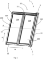
- a first embodiment of a roof window arrangement 1 is shown.
- the roof window arrangement 1 is intended to be installed in an inclined roof surface (not shown).
- the roof window arrangement 1 comprises a common stationary frame 10, a first window unit 100 and a second window unit 200.
- the common stationary frame 10 comprises a top frame member 11 and a bottom frame member 12 extending in a width direction W.
- the common stationary frame 10 further comprises two side frame members 13, 14 extending in a height direction H, and acts as a single stationary frame for all the window units.
- the common stationary frame 10 is configured to be built into the roof surface and is stationary relative to the roof structure.
- the common stationary frame 10 is connected to the underlying roof structure by means of a set of fittings represented by mounting brackets 3.
- a covering assembly generally designated 5 is shown as well. The covering assembly 5 provides covering for each window unit 100, 200.
- Each window unit comprises a pane 104, 204 in a pane-carrying sash 150, 250, and as best visualized in Fig. 2-4 , the sash 150, 250 of each window unit 100, 200 further comprises a top sash member 151, 251, a bottom sash member 152, 252, and two side sash members, 153, 154, 253, 254.
- the panes 104, 204 of the window units forms part of a two-layered or three-layered insulating glazing unit (IGU).
- the window units 100, 200 are configured in a side-by-side configuration.
- a side-by-side configuration is here to be understood as a side sash member of one window unit neighbouring a side sash member of another window unit.
- the neighbouring side sash members 154, 253 of the window units may be spaced apart such as by a mullion 50 as shown in Fig. 2 and still be considered as neighbouring.
- the common stationary frame 10 and sashes 150, 250 are described as rectangular structures, some principles of the presented concepts may be applicable to other geometrical shapes as well.
- the roof window arrangement 1 is shown as comprising two window units 100, 200, however the roof window arrangement 1 may comprise a third window unit.
- the third window unit may be configured in a side-by-side configuration with either of the first and second window unit.
- a hinge axis ⁇ is also shown, which is best described with Fig. 2 where a roof window arrangement 1 is shown from an interior side.
- the roof window arrangement 1 is shown in a first operational condition where the first window unit 100 is open about the horizontal centre hinge axis ⁇ defined by a set of hinges (not shown) arranged substantially at the centre of the window units in the height direction H.
- the hinges may be of any suitable kind such as pivot hinges disclosed in Applicant's EP 1 038 083 B1 , EP 1 781 883 B1 , EP 2 770 149 B1 , and EP 2 770 146 B1 or as a so-called pantograph hinge as described in Applicant's international application WO 2017/076416 A1 .
- the top sash member 151 of the first window unit 100 opens into the interior and the bottom sash member 152 opens out to the exterior.
- a handle 160 is arranged on the top sash member 151 for opening the first window unit 100 in the first operational condition.
- the handle 160 may form part of a top sash module 1411 (cf. Fig. 4 ) such as disclosed in Applicant's patent EP 2 751 355 B1 .
- the top sash module 1411 comprises a lock 117 configured to lock the sash of the first window unit to the stationary frame 10.
- the second window unit 200 may comprise a similar top sash module 2411 with a lock 217 as shown in Fig. 4 .
- the second window unit 200 is only openable as a part of the common openable sash in the second operational condition.
- a hinge is arranged between the side sash member 153 and the side frame member 13.
- a second hinge is arranged between the side sash member 154 and a mullion 50, but alternatively a hinge between the side sash member 154 and side sash member 253 may be conceived.
- Fig. 3 shows a roof window arrangement 1 in the first operational condition
- the second window unit 200 also comprises a handle 260 for opening the second window unit in the first operational condition around the centre hinge axis ⁇ as shown in Fig. 4 .
- Figs. 2-4 show embodiments of roof window arrangements 1 comprising the mullion 50 arranged between the first window unit 100 and the second window unit 200.
- mullion 50 extends between and is fixed to the top frame member 11 and bottom frame member 12 when the window is in a closed configuration or when the roof window arrangement 1 is in the first operational condition.
- each window unit 100, 200 has a hinge connection between a side sash member 153, 254 and a side frame member 13, 14, and between a side sash member 154, 253 and the mullion 50, and the hinges are arranged along the centre hinge axis ⁇ .
- Fig. 5A the roof window arrangement 1 is shown in the second operational condition where the first window unit 100 and second window unit 200 are configured to open as a common openable sash.
- the common openable sash is top hung and opens about an axis running in the width direction in approximation of the top frame element 11 of the stationary frame, however the common openable sash may alternatively open around the centre hinge axis ⁇ .
- a handle 60 for opening the common openable sash in the second operational condition is here arranged in the mullion 50. Additionally, the mullion and the top frame member 11 are connected via a hinge connection (not shown) allowing the mullion 50 to open as a part of the common openable sash.
- Fig. 5B shows a line sketch of a roof window arrangement 1 showing the common stationary frame 10 and an intermediate frame 20 with a top intermediate frame member 21, a bottom intermediate frame member 22, and two side intermediate frame members 23 and 24.
- the stationary frame 10 is sketched in dotted lines and the intermediate frame 20 is sketched in solid lines.
- the intermediate frame members form a rectangular intermediate frame structure and the first window unit 100 and second window unit 200 are arranged herein, also sketched as dotted lines.
- the rectangular intermediate frame structure provides a stabilizing structure for the window units 100 and 200 in the second operational condition.
- FIG. 5B shows how the intermediate frame 20 serves as a stabilizing structure for the mullion 50, which is connected to the top intermediate frame member 21 in one end and to the bottom intermediate frame member 22 in the other end.
- the mullion 50 is similarly sketched as a dotted line.
- Figs. 6A-6B show a part of a roof window arrangement 1 with a coupling arrangement 70 configured to uncouple the first window unit 100 and second window unit 200 in the first operational condition and couple the first window unit 100 and second window unit 200 in the second operational condition.
- the coupling arrangement 70 may be comprised in the mullion 50 where the coupling arrangement 70 is activated by turning the handle 60.
- the handle 60 and the coupling arrangement 70 may be linked in any suitable way, such as an espagnolette mechanism (not shown).
- espagnolette mechanisms are well-known to the skilled person and used in a variety of window types, including façade windows.
- the coupling arrangement 70 further couples the mullion 50 to the stationary frame 10 in the first operational condition and uncouples the mullion 50 and stationary frame 10 in the second operational condition.
- a part of the roof window arrangement 1 is shown in the first operational condition where the mullion 50 is coupled to the common stationary frame 10 by a mullion pin 55 arranged between the mullion 55 and the common stationary frame 10.
- the mullion pin 55 ensures that the mullion is fixed to the stationary frame 10 when the roof window arrangement 1 is in the first operational condition and is able to rotate with the window units 100, 200 in the second operational condition.
- Fig. 6A further shows the coupling arrangement 70 comprising a first window unit pin 155 and a second window unit pin 255 arranged in the mullion 50.
- the window unit pins 155, 255 are here in an uncoupled state, allowing the first window unit 100 and second window unit 200 to open independently.
- the mullion 50 is fixed to the stationary frame 10 by the mullion pin 55.
- the mullion pin 55 is retracted into the mullion 50 while the window pins 155, 255 couple the window units 100, 200 to the mullion 50 such that the window units 100, 200 are configured to open as a common openable sash together with the mullion 50.
- the coupling arrangement 70 prevents the window units from opening in the first operational condition while the roof window arrangement 1 is in the second operational condition and vice versa.
- the roof window arrangement 1 further comprises a lifting device 7 for opening the common openable sash in the second operational condition, as shown in Fig. 5A .
- the lifting device 7 is arranged between the side frame member 13 and side sash member 153 of the first window unit.
- a second lifting device 7 (not shown) is arranged between the side frame member 14 and the side sash member of the second window 254.
- the lifting device is arranged to pull on the common openable frame in the second operational condition. Details of the principles of such a lifting device 7 are found in Applicant's European patent No. 3 714 125 B1 .
Landscapes
- Engineering & Computer Science (AREA)
- Civil Engineering (AREA)
- Structural Engineering (AREA)
- Architecture (AREA)
- Door And Window Frames Mounted To Openings (AREA)
- Wing Frames And Configurations (AREA)
- Window Of Vehicle (AREA)
Abstract
Description
- The present invention relates to a roof window arrangement comprising a common stationary frame configured to be built into a roof surface, the common stationary frame having a top frame member and a bottom frame member extending in a width direction, and two side frame members extending in a height direction, the roof window arrangement further comprising at least a first window unit and a second window unit configured in a side-by-side configuration where each window unit comprises a pane-carrying sash, with a top sash member, a bottom sash member and two side sash members.
- Roof windows to be installed in inclined roof surfaces come in a variety of types, and are either installed as stand-alone window units, in which all sides of the roof window borders on the roofing, or in roof window arrangements where several window units are built together to combine into larger arrays providing a larger light influx into a room of a building, and in which only outer sides of the outermost window units border on the surrounding roofing. Configurations of twin or quadruple roof window arrangements installed side-by-side and/or above each other, respectively, are shown and described in Applicant's published international application
WO 2004/055291 A1 . - In a roof structure comprising rafters and battens, at least one rafter and a number of battens will typically need to be removed to provide a sufficiently large aperture in the roof surface and roof structure to accommodate such roof window arrangements. In Applicant's European patent No.
EP3406818 B1 corresponding to commercial counterpart VELUXO Dormer, a roof window arrangement with two rows of each three window units are connected to a respective frame structure installed in the roof structure. The frame structure usually comprises a common frame encompassing all the individual window units and the window units are typically separated by structural elements such as mullions which are fixed to the frame structure to allow some or all window units to be opened individually. The mullions provide stability and a place to arrange hinges for the window units, however the large aperture created by removal of the rafter(s) is not fully utilised because the mullions divide the aperture into several small openings. So even though the prior art window arrangements function well, they do not utilize the aperture in the roof structure optimally. - With this background, it is therefore an object of the invention to provide a roof window arrangement that solves or at least alleviates this problem.
- In a first aspect, this and further objects are achieved with a roof window arrangement of the kind mentioned in the introduction which is furthermore characterised in that at least one of the window units has an openable pane-carrying sash which opens about a horizontal centre hinge axis defined by a set of hinges arranged substantially at the centre of the window units in the height direction in a first operational condition,
and where the at least first window unit and second window unit are configured to open as a common openable sash in a second operational condition. - In this way, the roof window arrangement with window units arranged in a side-by-side configuration can be individually operated in the first operational condition and the window units of roof window arrangement can open as a single window unit in the second operational condition.
- One advantage of the second operational condition is that the roof window arrangement functions better as a fire escape.
- Another advantage of the second operational condition is that the roof window arrangement provides a better utilization of the aperture created to accommodate the roof window arrangement in the roof surface.
- The common openable sash is top hung. Top hung is here to be understood as being openable about a horizontal axis extending in the width direction in proximity to the top frame member.
- In preferred embodiments, each of the window units has an openable pane-carrying sash which opens about the centre hinge axis. Alternatively, at least the second window unit is only openable as part of the common openable sash in the second operational condition.
- Each window unit configured to open about the centre hinge axis in the first operational condition has at least two associated hinges arranged substantially along the centre hinge axis.
- In the preferred embodiments, the roof window arrangement further comprises a mullion arranged between the first window unit and the second window unit. One or more hinges along the centre hinge axis may be arranged on the mullion. The mullion opens as part of the common openable sash in the second operational condition and is fixed to the common stationary frame in the first operational condition. Preferably, the mullion is connected to the top frame member of the common stationary frame by a hinge connection to open as part of the top hung common openable sash.
- The at least first window unit and second window unit may be arranged in an intermediate frame. The intermediate frame is arranged in the common stationary frame and forms part of the common openable sash. The intermediate frame preferably comprises a top intermediate frame member, a bottom intermediate frame member, and two side intermediate frame members. This provides a stable intermediate frame in all operational conditions especially in the second operational condition.
- The common openable sash may be top hung via the intermediate frame. The intermediate frame is especially advantageous in embodiments where at least the second window unit is only openable in the second operational condition. In these embodiments, at least one of the sash members of the second window unit may form part of the intermediate frame. The intermediate frame opens as part of the common openable sash in the second operational condition and is fixed to the common stationary frame in the first operational condition.
- In preferred embodiments, the roof window arrangement comprises a coupling arrangement configured to uncouple the at least first window unit and second window unit in the first operational condition and couple the at least first window unit and second window unit in the second operational condition. The coupling arrangement is configured to couple the window units to function as a common openable sash in the second operational condition. The coupling arrangement may be arranged in the mullion and/or intermediate frame. The coupling arrangement may comprise an espagnolette mechanism. The coupling arrangement may further comprise a plurality of pins. A mullion pin may be arranged between the mullion and stationary frame. Similarly, an intermediate frame pin may be arranged between the intermediate frame and stationary frame.
- The mullion pin may couple the mullion and stationary frame in the first operational condition and uncouple the mullion and stationary frame in the second operational condition. Similarly, the intermediate frame pin may couple the intermediate frame and stationary frame in the first operational condition and uncouple the intermediate frame and stationary frame in the second operational condition.
- To couple the window units, the coupling arrangement may further comprise at least a first window unit pin that uncouples the first window unit from the mullion and/or intermediate frame in the first operational condition, and couples the first window unit and mullion and/or intermediate frame in the second operational condition. Additionally, the coupling arrangement may comprise a second window unit pin that uncouples the second window unit from the mullion and/or intermediate frame in the first operational condition, and couples the second window unit and mullion and/or intermediate frame in the second operational condition. In this way, the window units may be coupled to form the common openable sash by being coupled to each other via the mullion. In embodiments without a mullion, it may be envisioned that the first window unit pin and/or second window unit pin engages directly with a neighbouring window unit to couple them together.
- The coupling arrangement may be operated by a handle. The handle and coupling arrangement may be linked via the espagnolette mechanism.
- Preferably, the coupling arrangement is arranged such that the window units are prevented from opening in the first operational condition when the window arrangement is opened in the second operational condition and vice versa.
- Other presently preferred embodiments and further advantages will be apparent from the subsequent detailed description and drawings.
- In the following description embodiments of the invention will be described with reference to the drawings, in which
-
Fig. 1 is a perspective view of a roof window arrangement in an embodiment of the invention, seen from an exterior side of the roof window arrangement. -
Fig. 2 is a perspective view of a roof window arrangement in an embodiment of the invention, seen from an interior side and in a first operational condition. -
Fig. 3 is a perspective view of a roof window arrangement in an embodiment of the invention, seen from an interior side and in a first operational condition. -
Fig. 4 is a perspective view of a roof window arrangement in an embodiment of the invention, seen from an interior side and in a first operational condition. -
Fig. 5A is a perspective view of a roof window arrangement in an embodiment of the invention, seen from an interior side and in a second operational condition. -
Fig. 5B is a perspective view of a roof window arrangement in an embodiment of the invention, showing an intermediate frame from an exterior side and in a second operational condition. -
Fig. 6A is a front view of a part of a roof window arrangement in an embodiment of the invention with a coupling arrangement, seen from an interior side and in a first operational condition. -
Fig. 6B is a front view of a part of a roof window arrangement in an embodiment of the invention with a coupling arrangement, seen from an interior side and in a second operational condition. - In the following detailed description, preferred embodiments of the present invention will be described. However, it is to be understood that features of the different embodiments are exchangeable between the embodiments and may be combined in different ways, unless anything else is specifically indicated. It may also be noted that, for the sake of clarity, the dimensions of certain components illustrated in the drawings may differ from the corresponding dimensions in real-life implementations.
- It is noted that terms such as "up", "down", "left-hand", "right-hand", "exterior", "interior", "outer", "inner" are relative and refers to the viewpoint in question. In general, when referred to an exterior side, this relates to a side of a roof window in the mounted condition facing the outdoors or external side of the building. Conversely, an interior side refers to a side facing the internal side of the building, i.e. typically a subjacent room including any light shaft. Terms such as "outwards" and "inwards" are directions generally perpendicular to an interior-exterior direction, taking as its base point a centre of the roof window.
- In the figures of the drawings, embodiments of a
roof window arrangement 1 according to the invention are shown. - Referring initially to
Fig. 1 , a first embodiment of aroof window arrangement 1 is shown. Theroof window arrangement 1 is intended to be installed in an inclined roof surface (not shown). - The
roof window arrangement 1 comprises a commonstationary frame 10, afirst window unit 100 and asecond window unit 200. The commonstationary frame 10 comprises atop frame member 11 and abottom frame member 12 extending in a width direction W. The commonstationary frame 10 further comprises twoside frame members stationary frame 10 is configured to be built into the roof surface and is stationary relative to the roof structure. The commonstationary frame 10 is connected to the underlying roof structure by means of a set of fittings represented by mountingbrackets 3. A covering assembly generally designated 5 is shown as well. The coveringassembly 5 provides covering for eachwindow unit - Each window unit comprises a
pane sash Fig. 2-4 , thesash window unit top sash member bottom sash member panes - The
window units side sash members mullion 50 as shown inFig. 2 and still be considered as neighbouring. While the commonstationary frame 10 andsashes - In
Fig. 1 theroof window arrangement 1 is shown as comprising twowindow units roof window arrangement 1 may comprise a third window unit. The third window unit may be configured in a side-by-side configuration with either of the first and second window unit. A hinge axis α is also shown, which is best described withFig. 2 where aroof window arrangement 1 is shown from an interior side. InFig. 2 , theroof window arrangement 1 is shown in a first operational condition where thefirst window unit 100 is open about the horizontal centre hinge axis α defined by a set of hinges (not shown) arranged substantially at the centre of the window units in the height direction H. The hinges may be of any suitable kind such as pivot hinges disclosed in Applicant'sEP 1 038 083 B1EP 1 781 883 B1EP 2 770 149 B1EP 2 770 146 B1WO 2017/076416 A1 . - In the
roof window arrangement 1 shown inFig. 2 , thetop sash member 151 of thefirst window unit 100 opens into the interior and thebottom sash member 152 opens out to the exterior. Ahandle 160 is arranged on thetop sash member 151 for opening thefirst window unit 100 in the first operational condition. Thehandle 160 may form part of a top sash module 1411 (cf.Fig. 4 ) such as disclosed in Applicant'spatent EP 2 751 355 B1 . Thetop sash module 1411 comprises alock 117 configured to lock the sash of the first window unit to thestationary frame 10. - In embodiments where the
second window unit 200 is also openable in the first operational condition it may comprise a similartop sash module 2411 with alock 217 as shown inFig. 4 . - In
Fig. 2 thesecond window unit 200 is only openable as a part of the common openable sash in the second operational condition. - In the embodiment shown in
Fig. 2 , a hinge is arranged between theside sash member 153 and theside frame member 13. A second hinge is arranged between theside sash member 154 and amullion 50, but alternatively a hinge between theside sash member 154 andside sash member 253 may be conceived. -
Fig. 3 shows aroof window arrangement 1 in the first operational condition, where thesecond window unit 200 also comprises ahandle 260 for opening the second window unit in the first operational condition around the centre hinge axis α as shown inFig. 4 . -
Figs. 2-4 show embodiments ofroof window arrangements 1 comprising themullion 50 arranged between thefirst window unit 100 and thesecond window unit 200. - In
Figs. 2-4 themullion 50 extends between and is fixed to thetop frame member 11 andbottom frame member 12 when the window is in a closed configuration or when theroof window arrangement 1 is in the first operational condition. - In the embodiments shown in
Figs. 3-4 , eachwindow unit side sash member side frame member side sash member mullion 50, and the hinges are arranged along the centre hinge axis α. By having hinges arranged between themullion 50 and thefirst window unit 100 andsecond window unit 200, respectively, an increased stability of theroof window arrangement 1 is achieved. - In
Fig. 5A theroof window arrangement 1 is shown in the second operational condition where thefirst window unit 100 andsecond window unit 200 are configured to open as a common openable sash. In this embodiment, the common openable sash is top hung and opens about an axis running in the width direction in approximation of thetop frame element 11 of the stationary frame, however the common openable sash may alternatively open around the centre hinge axis α. - A
handle 60 for opening the common openable sash in the second operational condition is here arranged in themullion 50. Additionally, the mullion and thetop frame member 11 are connected via a hinge connection (not shown) allowing themullion 50 to open as a part of the common openable sash. -
Fig. 5B shows a line sketch of aroof window arrangement 1 showing the commonstationary frame 10 and anintermediate frame 20 with a topintermediate frame member 21, a bottom intermediate frame member 22, and two sideintermediate frame members stationary frame 10 is sketched in dotted lines and theintermediate frame 20 is sketched in solid lines. The intermediate frame members form a rectangular intermediate frame structure and thefirst window unit 100 andsecond window unit 200 are arranged herein, also sketched as dotted lines. As seen inFig 5B the rectangular intermediate frame structure provides a stabilizing structure for thewindow units Fig. 5B shows how theintermediate frame 20 serves as a stabilizing structure for themullion 50, which is connected to the topintermediate frame member 21 in one end and to the bottom intermediate frame member 22 in the other end. Themullion 50 is similarly sketched as a dotted line. -
Figs. 6A-6B show a part of aroof window arrangement 1 with acoupling arrangement 70 configured to uncouple thefirst window unit 100 andsecond window unit 200 in the first operational condition and couple thefirst window unit 100 andsecond window unit 200 in the second operational condition. - As shown in
Figs. 6A-6B thecoupling arrangement 70 may be comprised in themullion 50 where thecoupling arrangement 70 is activated by turning thehandle 60. - The
handle 60 and thecoupling arrangement 70 may be linked in any suitable way, such as an espagnolette mechanism (not shown). Such espagnolette mechanisms are well-known to the skilled person and used in a variety of window types, including façade windows. - In
Figs. 6A-6B thecoupling arrangement 70 further couples themullion 50 to thestationary frame 10 in the first operational condition and uncouples themullion 50 andstationary frame 10 in the second operational condition. - In
Fig. 6A a part of theroof window arrangement 1 is shown in the first operational condition where themullion 50 is coupled to the commonstationary frame 10 by amullion pin 55 arranged between themullion 55 and the commonstationary frame 10. Themullion pin 55 ensures that the mullion is fixed to thestationary frame 10 when theroof window arrangement 1 is in the first operational condition and is able to rotate with thewindow units -
Fig. 6A further shows thecoupling arrangement 70 comprising a firstwindow unit pin 155 and a secondwindow unit pin 255 arranged in themullion 50. The window unit pins 155, 255 are here in an uncoupled state, allowing thefirst window unit 100 andsecond window unit 200 to open independently. Additionally, themullion 50 is fixed to thestationary frame 10 by themullion pin 55. - By turning the
handle 60 as indicated by the arrow inFig. 6B , themullion pin 55 is retracted into themullion 50 while the window pins 155, 255 couple thewindow units mullion 50 such that thewindow units mullion 50. - The
coupling arrangement 70 prevents the window units from opening in the first operational condition while theroof window arrangement 1 is in the second operational condition and vice versa. - The
roof window arrangement 1 further comprises alifting device 7 for opening the common openable sash in the second operational condition, as shown inFig. 5A . Thelifting device 7 is arranged between theside frame member 13 andside sash member 153 of the first window unit. A second lifting device 7 (not shown) is arranged between theside frame member 14 and the side sash member of thesecond window 254. The lifting device is arranged to pull on the common openable frame in the second operational condition. Details of the principles of such alifting device 7 are found in Applicant'sEuropean patent No. 3 714 125 B1 . -
- 1
- Roof window arrangement
- 3
- Mounting bracket
- 5
- Covering assembly
- 7
- Lifting device
- 10
- Common stationary frame
- 11
- Top frame member
- 12
- Bottom frame member
- 13
- Side frame member
- 14
- Side frame member
- 20
- Intermediate frame
- 21
- Top intermediate frame member
- 22
- Bottom intermediate frame member
- 23
- Side intermediate frame member
- 24
- Side intermediate frame member
- 50
- Mullion
- 55
- Mullion pin
- 60
- Handle
- 100
- First window unit
- 104
- Pane
- 117
- Lock
- 150
- First pane-carrying sash
- 151
- Top sash member
- 152
- Bottom sash member
- 153
- Side sash member
- 154
- Side sash member
- 155
- First window unit pin
- 160
- Handle
- 200
- Second window unit
- 204
- Pane
- 217
- Lock
- 250
- Second pane-carrying sash
- 251
- Top sash member
- 252
- Bottom sash member
- 253
- Side sash member
- 254
- Side sash member
- 255
- Second window unit pin
- 260
- Handle
- 1411
- Top sash module
- 2411
- Top sash module
- α
- centre hinge axis
- H
- Height direction
- W
- Width direction
Claims (9)
- A roof window arrangement (1) comprising a common stationary frame (10) configured to be built into a roof surface, the common stationary frame having a top frame member (11) and a bottom frame member (12) extending in a width direction (W), and two side frame members (13, 14) extending in a height direction (H),the roof window arrangement further comprising at least a first window unit (100) and a second window unit (200) configured in a side-by-side configuration, where each window unit (100, 200) comprises a pane-carrying sash (150, 250), with a top sash member (151, 251), a bottom sash member (152, 252) and two side sash members (153, 154, 253, 254), and where at least one of the window units (100, 200) has an openable pane-carrying sash which opens about a horizontal centre hinge axis (α) defined by a set of hinges arranged substantially at the centre of the window units in the height direction (H) in a first operational condition, andwhere the at least first window unit (100) and second window unit (200) are configured to open as a common openable sash in a second operational condition, andwhere the common openable sash is top hung.
- A roof window arrangement according to any one of the preceding claims, where each of the window units (100, 200) has an openable pane-carrying sash (150, 250) which opens about the centre hinge axis (α).
- A roof window arrangement according to any one of the preceding claims, wherein the at least first window unit (100) and second window unit (200) are arranged in an intermediate frame (20).
- A roof window arrangement according to any one of the preceding claims, further comprising a coupling arrangement (70) configured to uncouple the at least first window unit (100) and second window unit (200) in the first operational condition and couple the at least first window unit (100) and second window unit (200) in the second operational condition.
- A roof window arrangement according to any one of the preceding claims, further comprising a mullion (50),wherein the mullion (50) is coupled to the top frame member (11) by a hinge, andwherein the mullion (50) comprises a mullion pin (55) configured to couple the mullion (50) to the bottom frame member (12) in the first operational condition and uncouple the mullion (50) from the bottom frame member (12) in the second operational condition.
- A roof window arrangement according to claim 5, wherein the mullion pin (55) forms part of a coupling arrangement (70), and
the coupling arrangement (70) further comprises a first window unit pin (155) configured for coupling the first window unit (100) to the mullion (50) in the second operational condition and uncouple the first window unit (100) from the mullion (50) in the first operational condition. - A roof window according to claim 6, wherein the coupling arrangement (70) further comprises a second window unit pin (255) configured for coupling the second window unit (200) to the mullion (50) in the second operational condition and uncouple the second window unit (200) from the mullion (50) in the first operational condition.
- A roof window arrangement according to any one of claims 5 to 7, wherein the coupling arrangement (70) forms part of an espagnolette mechanism.
- A roof window arrangement according to any one of claims 5 to 8, wherein the coupling arrangement (70) is operated by a handle (60), and wherein the handle (60) is configured for opening the common openable sash in the second operational condition.
Applications Claiming Priority (1)
| Application Number | Priority Date | Filing Date | Title |
|---|---|---|---|
| DKPA202370427A DK182237B1 (en) | 2023-08-21 | 2023-08-21 | A roof window arrangement comprising a common stationary frame and at least a first window unit and a second window unit |
Publications (1)
| Publication Number | Publication Date |
|---|---|
| EP4512974A1 true EP4512974A1 (en) | 2025-02-26 |
Family
ID=93461414
Family Applications (1)
| Application Number | Title | Priority Date | Filing Date |
|---|---|---|---|
| EP24195360.3A Pending EP4512974A1 (en) | 2023-08-21 | 2024-08-20 | A roof window arrangement comprising a common stationary frame and at least a first window unit and a second window unit |
Country Status (2)
| Country | Link |
|---|---|
| EP (1) | EP4512974A1 (en) |
| DK (1) | DK182237B1 (en) |
Citations (11)
| Publication number | Priority date | Publication date | Assignee | Title |
|---|---|---|---|---|
| EP1038083B1 (en) | 1997-11-11 | 2002-03-27 | VKR Holding A/S | A hinge fitting for a pivotal window |
| WO2004055291A1 (en) | 2002-12-16 | 2004-07-01 | Vkr Holding A/S | Sheet flashing for roof windows |
| EP1781883B1 (en) | 2004-07-02 | 2010-08-11 | VKR Holding A/S | Hinge fitting having an intermediate member, window comprising such hinge fittings and use of such a hinge fitting |
| EP2751355B1 (en) | 2011-10-04 | 2015-11-25 | VKR Holding A/S | A roof window with a top sash module |
| WO2017076416A1 (en) | 2015-11-06 | 2017-05-11 | Vkr Holding A/S | A hinge for a roof window, and a roof window including a set of hinges |
| EP2770146B1 (en) | 2013-02-22 | 2018-02-14 | VKR Holding A/S | An improved pivot hinge fitting and a roof window comprising such a hinge fitting |
| EP2770149B1 (en) | 2013-02-22 | 2018-02-14 | VKR Holding A/S | A roof window having a lifting device and hinge connection |
| EP3406818B1 (en) | 2017-05-24 | 2019-06-12 | VKR Holding A/S | Dormer assembly |
| EP3828359A1 (en) * | 2019-11-29 | 2021-06-02 | VKR Holding A/S | A roof window arrangement comprising a plurality of sash structures and a common frame, and including a covering assembly, and method of manufacturing such a roof window arrangement |
| EP3714125B1 (en) | 2017-11-24 | 2021-09-08 | VKR Holding A/S | Roof window with a primary frame and at least one secondary frame, method for installing such a roof window and method for dismantling a secondary frame of the roof window |
| EP4141189A1 (en) * | 2021-08-31 | 2023-03-01 | VKR Holding A/S | Roof window comprising removable insulated glass units arranged in a common movable frame |
Family Cites Families (2)
| Publication number | Priority date | Publication date | Assignee | Title |
|---|---|---|---|---|
| FR2570409B1 (en) * | 1984-09-17 | 1989-12-29 | Eger Wilhelm | PIVOTING AND SLIDING THREE-DIMENSIONAL WINDOWS FOR SLOPED ROOFS |
| CN210685754U (en) * | 2019-08-30 | 2020-06-05 | 天津雍鑫亿达门窗有限公司 | Outward opening type aluminum window |
-
2023
- 2023-08-21 DK DKPA202370427A patent/DK182237B1/en active IP Right Grant
-
2024
- 2024-08-20 EP EP24195360.3A patent/EP4512974A1/en active Pending
Patent Citations (11)
| Publication number | Priority date | Publication date | Assignee | Title |
|---|---|---|---|---|
| EP1038083B1 (en) | 1997-11-11 | 2002-03-27 | VKR Holding A/S | A hinge fitting for a pivotal window |
| WO2004055291A1 (en) | 2002-12-16 | 2004-07-01 | Vkr Holding A/S | Sheet flashing for roof windows |
| EP1781883B1 (en) | 2004-07-02 | 2010-08-11 | VKR Holding A/S | Hinge fitting having an intermediate member, window comprising such hinge fittings and use of such a hinge fitting |
| EP2751355B1 (en) | 2011-10-04 | 2015-11-25 | VKR Holding A/S | A roof window with a top sash module |
| EP2770146B1 (en) | 2013-02-22 | 2018-02-14 | VKR Holding A/S | An improved pivot hinge fitting and a roof window comprising such a hinge fitting |
| EP2770149B1 (en) | 2013-02-22 | 2018-02-14 | VKR Holding A/S | A roof window having a lifting device and hinge connection |
| WO2017076416A1 (en) | 2015-11-06 | 2017-05-11 | Vkr Holding A/S | A hinge for a roof window, and a roof window including a set of hinges |
| EP3406818B1 (en) | 2017-05-24 | 2019-06-12 | VKR Holding A/S | Dormer assembly |
| EP3714125B1 (en) | 2017-11-24 | 2021-09-08 | VKR Holding A/S | Roof window with a primary frame and at least one secondary frame, method for installing such a roof window and method for dismantling a secondary frame of the roof window |
| EP3828359A1 (en) * | 2019-11-29 | 2021-06-02 | VKR Holding A/S | A roof window arrangement comprising a plurality of sash structures and a common frame, and including a covering assembly, and method of manufacturing such a roof window arrangement |
| EP4141189A1 (en) * | 2021-08-31 | 2023-03-01 | VKR Holding A/S | Roof window comprising removable insulated glass units arranged in a common movable frame |
Also Published As
| Publication number | Publication date |
|---|---|
| DK202370427A1 (en) | 2025-03-24 |
| DK182237B1 (en) | 2025-12-19 |
Similar Documents
| Publication | Publication Date | Title |
|---|---|---|
| RU2184829C1 (en) | Mansard dormer window with facing members of window-frame and leaf | |
| EP3348737A1 (en) | Roof window particularly for flat roofs | |
| US6167661B1 (en) | Window, in particular for mounting in an inclined roof surface | |
| EP3828359B1 (en) | A roof window arrangement comprising a plurality of sash structures and a common frame, and including a covering assembly, and method of manufacturing such a roof window arrangement | |
| DK182237B1 (en) | A roof window arrangement comprising a common stationary frame and at least a first window unit and a second window unit | |
| EP4257772B1 (en) | A roof window arrangement comprising a plurality of window units and a common frame, and method of installing such a roof window arrangement | |
| KR102632220B1 (en) | Window having glass guardrail | |
| CN1266365C (en) | A reversible window, use thereof and a guide device for a reversible window | |
| KR100914735B1 (en) | Container connectable passages to one another | |
| EP3779088B1 (en) | A skylight window with an igu close to the window frame | |
| US6659157B1 (en) | Overhead bi-fold door construction | |
| EP4575129B1 (en) | Roof window with ventilation arrangement | |
| PL222228B1 (en) | Dormer with arched roof, especially a prefabricated one and roof windows especially for dormers | |
| KR102152139B1 (en) | System window | |
| CN213980430U (en) | Curtain wall type window convenient to install | |
| EP1645695B1 (en) | Roof window assembly | |
| JPH0323037Y2 (en) | ||
| JP3961149B2 (en) | Building roof balcony | |
| JPS61102934A (en) | Roof unit with skylight | |
| JP2886153B1 (en) | Folding structure | |
| CN117489014A (en) | An installation system and installation method for an openable aluminum plate decorative strip with ventilation function | |
| CA2410202C (en) | Overhead bi-fold door construction | |
| JPS5938878Y2 (en) | High watertight satsushi | |
| JP4543050B2 (en) | Building roof balcony | |
| KR20250118138A (en) | Installation Structure for Connecting Modularized Windows and Doors comprising Improved Installation Structure of the Turn-in Door and convenience of construction and maintenance |
Legal Events
| Date | Code | Title | Description |
|---|---|---|---|
| PUAI | Public reference made under article 153(3) epc to a published international application that has entered the european phase |
Free format text: ORIGINAL CODE: 0009012 |
|
| STAA | Information on the status of an ep patent application or granted ep patent |
Free format text: STATUS: THE APPLICATION HAS BEEN PUBLISHED |
|
| AK | Designated contracting states |
Kind code of ref document: A1 Designated state(s): AL AT BE BG CH CY CZ DE DK EE ES FI FR GB GR HR HU IE IS IT LI LT LU LV MC ME MK MT NL NO PL PT RO RS SE SI SK SM TR |
|
| STAA | Information on the status of an ep patent application or granted ep patent |
Free format text: STATUS: REQUEST FOR EXAMINATION WAS MADE |
|
| 17P | Request for examination filed |
Effective date: 20250825 |
|
| GRAP | Despatch of communication of intention to grant a patent |
Free format text: ORIGINAL CODE: EPIDOSNIGR1 |
|
| STAA | Information on the status of an ep patent application or granted ep patent |
Free format text: STATUS: GRANT OF PATENT IS INTENDED |
|
| INTG | Intention to grant announced |
Effective date: 20260127 |
|
| GRAS | Grant fee paid |
Free format text: ORIGINAL CODE: EPIDOSNIGR3 |