EP4512951A1 - Added agent putting device and clothes treatment apparatus - Google Patents
Added agent putting device and clothes treatment apparatus Download PDFInfo
- Publication number
- EP4512951A1 EP4512951A1 EP23791027.8A EP23791027A EP4512951A1 EP 4512951 A1 EP4512951 A1 EP 4512951A1 EP 23791027 A EP23791027 A EP 23791027A EP 4512951 A1 EP4512951 A1 EP 4512951A1
- Authority
- EP
- European Patent Office
- Prior art keywords
- cover plate
- air
- laundry
- air duct
- groove
- Prior art date
- Legal status (The legal status is an assumption and is not a legal conclusion. Google has not performed a legal analysis and makes no representation as to the accuracy of the status listed.)
- Pending
Links
Images








Classifications
-
- D—TEXTILES; PAPER
- D06—TREATMENT OF TEXTILES OR THE LIKE; LAUNDERING; FLEXIBLE MATERIALS NOT OTHERWISE PROVIDED FOR
- D06F—LAUNDERING, DRYING, IRONING, PRESSING OR FOLDING TEXTILE ARTICLES
- D06F39/00—Details of washing machines not specific to a single type of machines covered by groups D06F9/00 - D06F27/00
- D06F39/02—Devices for adding soap or other washing agents
- D06F39/028—Arrangements for selectively supplying water to detergent compartments
-
- D—TEXTILES; PAPER
- D06—TREATMENT OF TEXTILES OR THE LIKE; LAUNDERING; FLEXIBLE MATERIALS NOT OTHERWISE PROVIDED FOR
- D06F—LAUNDERING, DRYING, IRONING, PRESSING OR FOLDING TEXTILE ARTICLES
- D06F39/00—Details of washing machines not specific to a single type of machines covered by groups D06F9/00 - D06F27/00
- D06F39/02—Devices for adding soap or other washing agents
-
- D—TEXTILES; PAPER
- D06—TREATMENT OF TEXTILES OR THE LIKE; LAUNDERING; FLEXIBLE MATERIALS NOT OTHERWISE PROVIDED FOR
- D06F—LAUNDERING, DRYING, IRONING, PRESSING OR FOLDING TEXTILE ARTICLES
- D06F58/00—Domestic laundry dryers
- D06F58/20—General details of domestic laundry dryers
- D06F58/203—Laundry conditioning arrangements
-
- D—TEXTILES; PAPER
- D06—TREATMENT OF TEXTILES OR THE LIKE; LAUNDERING; FLEXIBLE MATERIALS NOT OTHERWISE PROVIDED FOR
- D06F—LAUNDERING, DRYING, IRONING, PRESSING OR FOLDING TEXTILE ARTICLES
- D06F58/00—Domestic laundry dryers
- D06F58/32—Control of operations performed in domestic laundry dryers
- D06F58/34—Control of operations performed in domestic laundry dryers characterised by the purpose or target of the control
- D06F58/36—Control of operational steps, e.g. for optimisation or improvement of operational steps depending on the condition of the laundry
- D06F58/44—Control of operational steps, e.g. for optimisation or improvement of operational steps depending on the condition of the laundry of conditioning or finishing, e.g. for smoothing or removing creases
-
- D—TEXTILES; PAPER
- D06—TREATMENT OF TEXTILES OR THE LIKE; LAUNDERING; FLEXIBLE MATERIALS NOT OTHERWISE PROVIDED FOR
- D06F—LAUNDERING, DRYING, IRONING, PRESSING OR FOLDING TEXTILE ARTICLES
- D06F2103/00—Parameters monitored or detected for the control of domestic laundry washing machines, washer-dryers or laundry dryers
- D06F2103/38—Time, e.g. duration
-
- D—TEXTILES; PAPER
- D06—TREATMENT OF TEXTILES OR THE LIKE; LAUNDERING; FLEXIBLE MATERIALS NOT OTHERWISE PROVIDED FOR
- D06F—LAUNDERING, DRYING, IRONING, PRESSING OR FOLDING TEXTILE ARTICLES
- D06F2105/00—Systems or parameters controlled or affected by the control systems of washing machines, washer-dryers or laundry dryers
- D06F2105/38—Conditioning or finishing, e.g. control of perfume injection
-
- D—TEXTILES; PAPER
- D06—TREATMENT OF TEXTILES OR THE LIKE; LAUNDERING; FLEXIBLE MATERIALS NOT OTHERWISE PROVIDED FOR
- D06F—LAUNDERING, DRYING, IRONING, PRESSING OR FOLDING TEXTILE ARTICLES
- D06F2105/00—Systems or parameters controlled or affected by the control systems of washing machines, washer-dryers or laundry dryers
- D06F2105/38—Conditioning or finishing, e.g. control of perfume injection
- D06F2105/40—Conditioning or finishing, e.g. control of perfume injection using water or steam
-
- D—TEXTILES; PAPER
- D06—TREATMENT OF TEXTILES OR THE LIKE; LAUNDERING; FLEXIBLE MATERIALS NOT OTHERWISE PROVIDED FOR
- D06F—LAUNDERING, DRYING, IRONING, PRESSING OR FOLDING TEXTILE ARTICLES
- D06F33/00—Control of operations performed in washing machines or washer-dryers
- D06F33/50—Control of washer-dryers characterised by the purpose or target of the control
- D06F33/52—Control of the operational steps, e.g. optimisation or improvement of operational steps depending on the condition of the laundry
- D06F33/65—Control of the operational steps, e.g. optimisation or improvement of operational steps depending on the condition of the laundry of conditioning or finishing phases, e.g. for smoothing or removing creases
Definitions
- the present invention belongs to the technical field of laundry treatment apparatus, relates to an additive dispensing device with an air duct, and in particular, relates to laundry treatment apparatus with the additive dispensing device.
- the additive dispensing device of the laundry treatment apparatus is installed on a body of a washing machine, and the additive dispensing device is provided with at least one dispensing chamber, so that user can manually put additives into the dispensing chamber.
- user puts any one kind or combinations of additives such as detergent, softener, fragrance agent, bleach, disinfectant, etc. into the laundry treatment cylinder to achieve the effects of washing, fragrance enhancement, disinfection, etc. on the laundry.
- the laundry is often in contact with the outside and attached with microorganisms.
- the microorganisms attached to the laundry remain inside the laundry treatment cylinder. Due to the long-term flow of washing water, a large amount of dirt and bacteria is accumulated on the outside of the laundry treatment cylinder. After the washing and caring processes are completed, a large amount of water vapor is still remained inside the laundry treatment cylinder to cause microbial growth and odor generation.
- the odorous substances remained in the machine body diffuse outward, causing discomfort to user and affecting user's experience.
- An additive dispensing device is provided to achieve a purpose of exchanging air between the additive dispensing device and the outside.
- An additive dispensing device comprises a dispensing box and a cover plate installed on a top of the dispensing box.
- a hollow chamber is formed inside the cover plate, an air duct is provided inside the hollow chamber, one end of the air duct is connected with an interior of the dispensing box, and another end is connected with the outside of the dispensing box.
- the air duct has an air inlet and an air outlet, the air inlet of the air duct is connected with the interior of the dispensing box, and the air outlet of the air duct is connected with the outside of the dispensing box.
- the cover plate includes an upper cover plate and a lower cover plate that are interlocked, and both the upper cover plate and the lower cover plate are provided with grooves with openings arranged opposite to each other.
- the groove of the upper cover plate and the groove of the lower cover plate are configured to cooperate with each other to close the openings to form the air duct.
- the air inlet and the air outlet are provided at a bottom of the groove of the lower cover plate.
- the cover plate includes an upper cover plate and a lower cover plate that are interlocked with each other.
- the lower cover plate is provided with a groove opening upward, a side of the upper cover plate facing and being in contact with the lower cover plate is a plane, a surface of a side wall of the groove of the lower cover plate facing the upper cover plate is correspondingly in contact with the plane of the upper cover plate to close the opening of the groove to form the air duct, and a bottom of the groove of the lower cover plate is provided with the air inlet and the air outlet.
- a filter is installed inside the air duct, and the filter is inserted into the air duct between the air inlet and the air outlet.
- the filter is detachably installed on the upper cover plate and/or the lower cover plate via a rotating shaft.
- the groove of the lower cover plate includes a first side wall and a second side wall arranged opposite to each other.
- the filter includes a filter frame and a filter screen installed on the filter frame, two ends of the filter frame are in contact with the first side wall and the second side wall of the groove of the lower cover plate, and a top of the filter frame is in contact with a lower surface of the upper cover plate.
- a part of the upper surface of the upper cover plate is recessed upward to form an accommodating groove of which a lower end is an opening, and an upper of the filter frame is inserted into the accommodating groove and in contact with side walls and a bottom of the accommodating groove.
- the upper cover plate is provided with a groove opening downward, and the groove of the upper cover plate and the groove of the lower cover plate are configured to cooperate with each other to close the openings to form the air duct.
- the groove of the upper cover plate includes a first side wall and a second side wall arranged opposite to each other. Two ends of the filter frame are correspondingly in contact with the first side wall and the second side wall of the groove of the upper cover plate.
- An accommodating groove is formed at a bottom of the groove of the upper cover plate.
- At least one dispensing chamber is provided in an interior of the dispensing box, and a part of the opening of the dispensing chamber is covered with a shielding plate, and a hollow portion is provided on the shielding plate and arranged correspondingly to the air inlet of the air duct in up and down direction.
- Another object of the present invention is to provide a laundry treatment apparatus to achieve the purpose of exchanging air between the interior of the laundry treatment cylinder and the external atmosphere.
- a laundry treatment apparatus comprises a laundry treatment cylinder and any one of the above additive dispensing devices, and one end of an air duct is connected with the interior of the laundry treatment cylinder.
- the present invention has the following advantages compared with the prior art.
- An additive dispensing device is provided in the present invention, to achieve the purpose of exchanging are between the additive dispensing device and the outside.
- An additive dispensing device comprises a water storage box with a hollow inside.
- An air duct is provided at a bottom of the water storage box, one end of the air duct is connected with an interior of the water storage box, and another end of the air duct is connected with the outside of the water storage box.
- the air duct has an air inlet connected with the outside of the water storage box, a through hole is provided at the bottom of the water storage box, and the air inlet of the air duct is connected with the interior of the water storage box through the through hole.
- An air outlet connected with the interior of the water storage box is provided on a side wall of the water storage box.
- a cover body is arranged on the bottom of the water storage box, and an accommodating chamber with an opening upward is formed inside the cover body.
- the water storage box and the cover body are configured to cooperate with each other to close the opening of the accommodating chamber to form an air duct, and an air inlet of the air duct is provided at one end of the cover body.
- the accommodating chamber is in a shape of an inverted cone or an inverted frustum with radial dimensions gradually narrowing from top to bottom, and the air inlet of the air duct is provided at a lowest point of the inverted cone or inverted frustum.
- a bottom wall of the accommodating chamber is recessed downward near the air inlet of the air duct to form a fluid guiding groove.
- the fluid guiding groove has a fluid guiding wall being opposite to the air inlet of the air duct, and the fluid guiding wall is extended upwardly and obliquely in a direction away from the air inlet of the air duct.
- a boss extending upwardly is provided in and interior of the water storage box, and a part of a top of the boss is recessed downward to form a fluid guiding groove.
- the air outlet is provided on the side wall of the water storage box, and a fluid guiding hole connected with the air outlet is provided on a side wall of the fluid guiding groove.
- the fluid guiding groove is a pressed groove with a notch
- the air duct is connected with the fluid guiding groove through the notch
- the notch and the fluid guiding hole are arranged at both ends of the fluid guiding groove and opposite to each other
- a bottom of the fluid guiding groove is an inclined surface extending upward.
- a filter is provided in the fluid guiding groove, and the filter is detachably mounted on side walls of the fluid guiding groove via a rotating shaft.
- the filter includes a filter frame and a filter screen installed on the filter frame, two ends of the filter frame are respectively in contact with the side walls of the fluid guiding groove being opposite to each other, and a bottom end of the filter frame is in contact with the bottom of the fluid guiding groove.
- Another object of the present invention is to provide a laundry treatment apparatus to achieve the purpose of exchanging air between the interior of the laundry treatment cylinder and the external atmosphere.
- a laundry treatment apparatus comprises a laundry treatment cylinder and any one of the above additive dispensing devices, wherein one end of an air duct is connected with an interior of the laundry treatment cylinder.
- the present invention has the following advantages compared with the prior art.
- the present invention also provides a method for a washing machine with a fresh air system.
- a method for controlling a washing machine with a fresh air system comprises the following steps:
- the drying device in S11 includes a heater and/or a drying fan.
- a washing process and/or a rinsing process are included before the drying process in S1.
- at least one process of adding a laundry additive is included.
- the process of adding the laundry additive comprises: mixing the laundry additive with water to form a mixture, and spraying the mixture directly onto the surface of laundry through a spraying device in multiple times.
- the washing process and/or the rinsing process are/is performed as follows:
- step S01 specifically includes the following steps: supplying water in the washing machine to a set water level; heating water to generate steam flowing into an inner cylinder, and turning on a drying fan to circulate air in the inner cylinder for increasing temperature and humidity in the inner cylinder and laundry; fully mixing the first laundry additive with water at one time, spraying a mixture having the first laundry additive into the inner cylinder of the washing machine by multiple times, and rotating the inner cylinder in stopping spraying; after a spraying process is completed, supplying water to a set water level, and then performing the washing process and/or the rinsing process in keeping a water temperature.
- the set water level of the washing machine is above a heating pipe and lower than the surface of the inner cylinder.
- step S00 draining water, weighing laundry after draining water out of the inner cylinder; determining the amount of water, the amount of the first laundry additive, and the amount of the second laundry additive added in the washing machine based on the weight of laundry.
- step S01 the water level is detected between step S01 and step S02. It is detected whether the water level reaches a set water level value by a water level sensor after the first laundry additive is added. If reaching the set water level value, a washing process is performed for the laundry. If the set water level value is not reached, water is supplied in the washing machine until the set water level value is reached. After supplying water, the washing process is performed for the laundry.
- the fragrance agent is placed in an inlet component of the fresh air device.
- the fragrance agent can be placed directly at the air inlet of a fresh air duct, or can be placed in the fragrance device placed at the air inlet of the fresh air duct.
- a heating device is arranged in the air inlet of the fresh air system.
- the heating device and the fragrance device are both arranged on the downstream from the fan.
- a washing machine with a fresh air system is controlled by the above-mentioned method.
- the present invention has the following advantages:
- Dispensing box 11. Shielding plate; 12. Hollow portion; 2. Cover plate; 21. Upper cover plate; 211. Groove; 212. Accommodating groove; 22. Lower cover plate; 221. Groove; 222. Mounting groove; 2221. Shaft hole; 2222. Mounting hole; 23. Air inlet; 24. Air outlet; 25. Filter; 251. Filter frame; 252. Filter screen; 253. Shaft seat; 254. Support seat; 26. Mounting shaft; 261. First mounting shaft; 262, Second mounting shaft; 27. Air discharge pipe; 3. Water storage box; 31. Through hole; 32. Air outlet; 33. Boss; 331. Fluid guiding groove; 332. Fluid guiding hole; 333.
- connection can be a fixed connection, a detachable connection or an integral connection; can be mechanical connection or electrical connection; and can be direct connection or can be indirect connection through an intermediate.
- connection can be a fixed connection, a detachable connection or an integral connection; can be mechanical connection or electrical connection; and can be direct connection or can be indirect connection through an intermediate.
- an additive dispensing device of the present invention includes a dispensing box 1 and a cover plate 2 installed on a top of the dispensing box 1.
- a hollow chamber is formed inside the cover plate 2
- an air duct is provided inside the hollow chamber, one end of the air duct is connected with the inside of the dispensing box 1, and the other end is connected with the outside of the dispensing box 1.
- the external atmosphere flows into the air duct through the dispensing box 1, and then fresh air flows into an interior of the laundry treatment cylinder through the air duct.
- the air inside the laundry treatment cylinder flows into an interior of the dispensing box 1 through the air duct, and then is discharged to the outside through the dispensing box 1.
- An air duct has an air inlet 23 and an air outlet 24, the air inlet 23 of the air duct is connected with an interior of the dispensing box 1, and the air outlet 24 of the air duct is connected with the outside of the dispensing box 1.
- the air inlet 23 of the air duct is connected with the interior of the dispensing box 1, so that the air duct is connected with the external atmosphere.
- the external atmosphere flows into the air duct through the air inlet 23, and fresh air flows into the interior of the laundry treatment apparatus through the air outlet 24 to replace air inside the laundry treatment apparatus.
- the cover plate 2 includes an upper cover plate 21 and a lower cover plate 22 that are interlocked.
- the upper cover plate 21 and the lower cover plate 22 are both provided with grooves with openings arranged opposite to each other.
- the groove 211 of the upper cover plate 21 and the groove 221 of the lower cover plate 22 cooperate with each other to close the openings to form the air duct, and the air inlet 23 and the air outlet 24 are provided at a bottom of the groove 221 of the lower cover plate 22.
- the upper cover plate 21 and the lower cover plate 22 are buckled together to form a hollow chamber, and a water inlet passage is provided inside the hollow chamber for feeding water into the dispensing box 1.
- the air duct is closed to prevent the air in the air duct from flowing into the water inlet passage.
- a filter 25 is installed inside the air duct.
- the filter 25 is inserted into the air duct between the air inlet 23 and the air outlet 24.
- the filter 25 is detachably installed on the upper cover plate 21 and/or the lower cover plate 22 via a rotating shaft.
- a filter 25 is installed inside the air duct for filtering the external air flowing into the air duct, to prevent impurities such as dust and lint in the external air from entering the interior of the laundry treatment cylinder through the air outlet 24 of the air duct to cause to contaminate the interior of the laundry treatment cylinder.
- the groove 221 of the lower cover plate 22 includes a first side wall and a second side wall that are opposite to each other.
- the filter 25 includes a filter frame 251 and a filter screen 252 installed on the filter frame 251. Two ends of the filter frame 251 are in contact with the first side wall and the second side wall of the groove 221 of the lower cover plate 22, and a top of the filter frame 251 is in contact with the upper surface of the upper cover plate 21.
- the filter frame 251 is in contact with the upper cover plate 21 and the lower cover plate 22, so that the air inside the air duct flows into the laundry treatment cylinder after being filtered by the filter 25, preventing impurities such as dust and lint in the external atmosphere from contaminating the laundry treatment cylinder and the laundry inside.
- the filter screen 252 is perpendicular to an air flow direction inside the air duct, thereby increasing the contact area between the filter screen 252 and air and enhancing the filtering effect.
- a bottom of the groove 221 of the lower cover plate 22 is recessed downward to form a mounting groove 222 of which an upper end is an opening.
- a shaft seat 253 is provided at a lower end of the filter frame 251. Shaft holes are respectively provided on the shaft seat 253 and side walls of the mounting groove 222 for allowing the mounting shaft 26 to pass through to connect the filter 25 with the lower cover plate 22.
- the filter 25 is installed on the upper cover plate 21 and/or the lower cover plate 22 via a rotating shaft.
- the filter 25 is detachably connected with and the cover plate 2, so users can remove or install the filter 25 by themselves, and it is convenient for the user to clean or replace the filter 25, further enhancing the user's favorability.
- a bottom end of the shaft seat 253 is embedded in the mounting groove 222 and is in contact with the bottom of the mounting groove 222, so that the filter 25 can fully filter the air inside the air duct.
- the mounting groove 222 has two side walls that are opposite to each other, and the two ends of the shaft seat 253 are detachably fixedly connected to the side walls of the mounting groove 222 being opposite to each other via the rotating shaft.
- shaft holes 2221 are formed on the side walls of the mounting groove 222, and includes a first shaft hole and a second shaft hole respectively arranged on the two side walls of the mounting groove 222.
- a first mounting shaft 261 and a second mounting shaft 262 are respectively arranged at both ends of the shaft seat 253 to pass through the first shaft hole and the second shaft hole respectively.
- the first mounting shaft 261 is integrated with the shaft seat 253, and the second mounting shaft 262 is movably connected with the shaft seat 253.
- the first mounting shaft 261 is fixed to the lower cover plate 22, and the second mounting shaft 262 is detachably connected to the lower cover plate 22, so that the filter 25 is detachably mounted on the lower cover plate 22.
- the filter 25 also includes a support seat 254 extending downward from the bottom end of the filter frame 251, and a mounting hole 2222 is provided on the bottom of the mounting groove 222 for the support seat 254 to be inserted in.
- the support seat 254 passes through the mounting hole 2222 and is placed between the dispensing box 1 and the lower cover plate 22.
- the support seat 254 it is convenient for user to disassemble or install the filter 25, thereby improving the assembly efficiency of the filter 25, and facilitating user to clean or replace the filter 25.
- part of the upper surface of the upper cover plate 21 is recessed upward to form an accommodating groove 212 of which a lower end is an opening.
- the upper of the filter frame 251 is inserted into the accommodating groove 212 and in contact with side walls and a bottom of the accommodating groove 212.
- the filter frame 251 is in contact with the side walls and the bottom of the accommodating groove 212 to ensure that the air inside the air duct flows into the interior of the laundry treatment cylinder after being fully filtered by the filter 25.
- the upper cover plate 21 is provided with a groove opening downward, and the groove 211 of the upper cover plate 21 and the groove 221 of the lower cover plate 22 cooperate with each other to close the opening to form an air duct.
- the groove 211 of the upper cover plate 21 includes a first side wall and a second side wall being opposite to each other, and both ends of the filter frame 251 are in contact with the first side wall and the second side wall of the groove 211 of the upper cover plate 21, and the accommodating groove 212 is formed at the bottom of the groove 211 of the upper cover plate 21, so that the upper of the filter frame 251 is embedded in the groove 211 of the upper cover plate 21 and partially embedded in the accommodating groove 212, thereby improving the sealing property of the air duct and fully filtering the air inside the air duct.
- the filter 25 filters the external air flowing into the air duct, preventing impurities such as dust and lint in the external atmosphere from entering the interior of the laundry treatment cylinder through the air outlet 24 of the air duct and contaminating the interior of the laundry treatment cylinder.
- the filter 25 is installed on the upper cover plate 21 and/or the lower cover plate 22 via a rotating shaft, so that user can remove or install the filter 25 by himself, and it is convenient for cleaning or replacing the filter 25.
- the cover plate 2 includes an upper cover plate 21 and a lower cover plate 22 that are buckled together.
- the lower cover plate 22 is provided with a groove with an opening upward, and a side of the upper cover plate 21 being in contact with the lower cover plate 22 is a plane.
- Surfaces of the side walls of the groove 221 of the lower cover plate 22 facing the upper cover plate 21 are correspondingly in contact with the plane of the upper cover plate 21 to close the opening of the groove to form an air duct.
- a bottom of the groove 221 of the lower cover plate 22 is provided with an air inlet 23 and an air outlet 24.
- the groove 221 of the lower cover plate 22 is in contact with the surface of the upper cover plate 21 to form an air duct. So it is facilitated to assemble the lower cover plate 22 with the upper cover plate 21, reduce the difficulty of assembly, and ensure the tightness of the air duct.
- part of the upper surface of the upper cover plate 21 is recessed upward to form an accommodating groove 212 of which a lower end is an opening.
- the upper of the filter frame 251 is inserted into the accommodating groove 212 and in contact with the side walls and the bottom of the accommodating groove 212, so that the air in the air duct can be filtered by the filter screen 252 and then flow to the air outlet 24 of the air duct.
- the groove 221 of the lower cover plate 22 is in contact with the surface of the upper cover plate 21 to form an air duct, so the difficulty of assembling the upper cover plate 21 and the lower cover plate 22 is reduced.
- the upper of the filter frame 251 is embedded in the accommodating groove 212 to improve the sealing performance of the air duct, so that the air in the air duct can be fully filtered.
- At least one dispensing chamber is provided in an interior of the dispensing box 1. Part of the opening of the dispensing chamber is covered with a shielding plate 11. A hollow portion 12 is formed on the shielding plate 11. The hollow portion 12 is arranged correspondingly to the air inlet 23 of the air duct in up and down direction.
- the hollow portion 12 on the shielding plate 11 is arranged correspondingly to the air inlet 23 of the air duct, so that the aromatic substances generated by volatilizing the fragrance agent pass through the hollow portion 12 and flow into the air duct. Thereby the laundry treatment cylinder and the laundry inside are fumigated, and odorous substances inside the laundry treatment cylinder is quickly removed.
- an additive dispensing device is provided in the embodiment of the present invention, which includes a water storage box 3 with a hollow inside.
- An air duct is provided at a bottom of the water storage box 3, one end of the air duct is connected with the interior of the water storage box 3, and the other end of the air duct is connected with the outside of the water storage box 3.
- the external air flows into the air duct through the water storage box 3.
- Fresh air can flow into the interior of the laundry treatment cylinder through the air duct, or the air inside the laundry treatment cylinder flows into the water storage box 3 through the air duct, so the air inside the laundry treatment cylinder is discharged to the outside. It is achieved to exchange air between the interior of the laundry treatment cylinder and the external atmosphere, to remove odors inside the laundry treatment cylinder, and further to improve user's experience.
- the air duct has an air inlet 42 connected with the outside of the water storage box 3, a through hole 31 is provided at the bottom of the water storage box 3, and the air inlet 42 of the air duct is connected with the interior the water storage box 3 through the through hole 31.
- An air outlet 32 connected with the interior of the water storage box 3 is provided on a side wall of the water storage box 3.
- a cover body 4 is arranged on the bottom of the water storage box 3.
- An accommodating chamber 41 of which a top end is an opening is formed inside the cover body 4, and the water storage box 3 and the cover body 4 cooperate with each other to close the opening of the accommodating chamber 41 to form an air duct.
- the air inlet 42 of the air duct is provided at one end of the cover body 4.
- the water storage box 3 and the cover body 4 cooperate with each other to close the opening of the accommodating chamber 41 to form an air duct, so that the air duct is in a closed state from the external atmosphere, thereby preventing the air flowing into the air duct from leaking to cause the odor substances inside the laundry treatment cylinder to spread and to affect user's experience.
- the accommodating chamber 41 is in the shape of an inverted cone or an inverted frustum, of which radial dimensions are gradually narrowed from top to bottom, and the air inlet 42 of the air duct is arranged at the lowest point of the inverted cone or the inverted frustum.
- the air inlet 42 of the air duct is arranged at the lowest point of the inverted cone or the inverted frustum, so that the air in the laundry treatment cylinder flows upward quickly after flowing into the air duct through the air inlet 42, and then flows into the water storage box 3 through the through hole 31 formed on the bottom of the water storage box 3, and finally discharged to the outside through the air outlet 32 on the side wall of the water storage box 3.
- the accommodating chamber 41 formed inside the cover body 4 is an inverted isosceles triangle with left and right sides gradually tilted toward the center, and the air inlet 42 is arranged at the lowest point of the inverted isosceles triangle, so that the air flowing into the air duct from the laundry treatment cylinder forms a vortex airflow at the air inlet 42, and the air quickly flows to the through hole 31. It is avoided that air is accumulated at the bottom of the accommodating chamber 41.
- the bottom wall of the accommodating chamber 41 is recessed downward near the air inlet 42 of the air duct to form a fluid guiding groove 43, and the fluid guiding groove 43 has a fluid guiding wall 431 being opposite to the air inlet 42 of the air duct.
- the fluid guiding wall 431 is extended upwardly and obliquely in a direction away from the air inlet 42 of the air duct.
- the fluid guiding wall 431 of a fluid guiding groove 331 extends upwardly and obliquely in a direction away from the air inlet 42 of the air duct, that is, the fluid guiding wall 431 of the fluid guiding groove 331 is extended obliquely in a direction of the air flow inside the air duct, so that the air inside the laundry treatment cylinder flows upward along a first side of the fluid guiding groove 331. It is avoided that air is accumulated at the bottom of the air duct, especially odor substances is accumulated at the bottom of the air duct and unable to be discharged to the outside.
- both the bottom of the water storage box 3 and the interior of the cover body 4 form an accommodating chamber with openings arranged opposite to each other.
- the accommodating chamber at the bottom of the water storage box 3 and the accommodating chamber 41 inside the cover body 4 cooperate with each other to close the openings to form an air duct, thereby increasing the space above the air duct.
- the air inside the laundry treatment cylinder can quickly flows into the air duct, and flows upward through the through hole 31 at the bottom of the water storage box 3 to flow into the interior of the water storage box 3.
- an accommodating chamber 41 with an opening upward is formed inside the cover body 4, and a side of the water storage box 3 facing the cover body 4 is a plate. Edge of the opening of the accommodating chamber formed inside the cover body 4 is bent outward to form a circle of flange, and the flange is in contact with a side of the water storage box 3 facing the cover body 4 to close the opening of the accommodating chamber 41 to form an air duct. So it is easy to assemble the water storage box 3 and the cover body 4 and the sealing performance of the air duct is ensured.
- the air duct is extended from a front end of the bottom of the water storage box 3 to a rear end of the bottom of the water storage box 3 to form a long strip of air duct extending in a length direction of the water storage box 3, so that the air inside the air duct flows from front to back, and finally is discharged to the outside. It is avoided that user catches the odorous substances in the air and feel discomfort.
- the air inlet 42, the through hole 31 and the air outlet 32 are arranged in sequence from front to back.
- An axis of the air outlet 32 is higher than an axis of the air inlet 42, so it is conducive that odorous substances with a smaller density than air inside the air duct quickly flows toward the air outlet 32 at the rear end.
- the radial dimensions of the accommodating chamber 41 formed inside the cover body 4 are gradually increased from front to back to prevent the air from accumulating above the through hole 31 to cause excessive local pressure in the air duct.
- the interior of the laundry treatment cylinder is communicated with the interior of the water storage box 3 through the air duct, so that the air in the laundry treatment cylinder flows into the interior of the water storage box 3 through the air duct, and is then discharged to the outside through the air outlet 32 on the side wall of the water storage box 3.
- odorous substances inside the laundry treatment cylinder are quickly discharged.
- FIG. 10 An interior of a water storage box 3 is provided with a boss 33 protruding and extending upwardly. Part of a top of the boss 33 is recessed downward to form a fluid guiding groove 331, a side wall of the water storage box 3 is provided with an air outlet 32, and the side wall of the fluid guiding groove 331 is provided with a fluid guiding hole 332 connected with the air outlet 32.
- the air inside the air duct flows into the water storage box 3 through the through hole 31.
- the air inside the water storage box 3 flows toward the fluid guiding hole 332 on the side wall of the fluid guiding groove 331, and finally discharged into the outside through the air outlet 32, thereby realizing ventilation of the laundry treatment cylinder.
- the fluid guiding groove 331 is a pressed groove with a notch 333, and the air duct is connected with the fluid guiding groove 331 through the notch 333.
- the notch 333 and the fluid guiding hole 332 are arranged at both ends of the fluid guiding groove 331 and opposite to each other, and the bottom of the fluid guiding groove 331 is an inclined surface extending upward.
- the air inside the water storage box 3 flows into the fluid guiding groove 331 through the notch 333.
- the bottom of the fluid guiding groove 331 is an inclined surface extending upward, so the air flows upward along the bottom of the drainage groove 331, especially odorous substances with lower density are quickly discharged out through the fluid guiding hole 332.
- a filter 34 is provided in the fluid guiding groove 331, and the filter 34 is detachably mounted on the side walls of the fluid guiding groove 331 via a rotating shaft.
- the filter 34 is installed on the side walls of the fluid guiding groove 331 via the rotating shaft, so that the filter 34 can be detachably connected with the side walls of the fluid guiding groove 331. It is convenient for users to replace or regularly clean the filter 34.
- the filter 34 is used for filtering the air flowing into the water storage box 3 through the air duct, so impurities such as dust and lint in the air is prevented from clogging the fluid guiding hole 332 to cause the air inside the laundry treatment cylinder to be unable to be discharged through the air duct.
- the filter 34 includes a filter frame 341 and a filter screen 342 installed on the filter frame 341.
- Two side ends of the filter frame 341 are respectively in contact with the side walls of the fluid guiding groove 331 being opposite to each other, and a bottom end of the filter frame 341 is in contact with a bottom of the fluid guiding groove 331.
- the air is filtered through the filter screen 342 to prevent air from flowing out from the two side ends of the filter frame 341 to block the fluid guiding hole 332.
- two side ends of the filter frame 341 are respectively provided with a positioning columns 343 extending toward the corresponding side wall of the fluid guiding groove 331.
- the side walls of the fluid guiding groove 331 are respectively provided with a notch 334 for installing the positioning columns 343 on the corresponding side walls, so that the filter 34 can be detachably installed on the side walls of the fluid guiding groove 331.
- a limit block 35 abutting against the filter 34 is provided in the fluid guiding groove 331.
- the filter 34 and the limit block 35 are arranged in sequence in a direction of the air flow, so that the filter 34 is firmly installed in the fluid guiding groove 331 to prevent the filter 34 from becoming loose due to the action of the air flow.
- the filter 34 is detachably installed on the side walls of the fluid guiding groove 331 via the rotating shaft, so it is convenient for user to replace or clean the filter 34.
- the filter 34 is used for filtering the air flowing into the water storage box 3 from the air duct to prevent impurities such as dust and lint in the air from clogging the fluid guiding hole 332.
- a laundry treatment apparatus in an embodiment of the present invention includes a laundry treatment cylinder and the additive dispensing device described in any one of Embodiments 1 to 3, and one end of the air duct is connected with the interior of the laundry treatment cylinder.
- an air inlet 23 of the air duct is connected with an interior of the dispensing box 1
- an air outlet 24 of the air duct is connected with an interior of the laundry treatment cylinder via an air discharge pipe 27.
- the external air flows into the air duct through the dispensing box 1, and the air inside the air duct is filtered by the filter 25 and then flows into the interior of the laundry treatment cylinder, thereby realizing to exchange air between the external atmosphere and the interior of the laundry treatment cylinder, and removing odor substances inside the laundry treatment cylinder.
- a laundry treatment apparatus in an embodiment of the present invention includes a laundry treatment cylinder and the additive dispensing device described in any one of Embodiment 4 and Embodiment 5.
- One end of the air duct is connected with an interior of the laundry treatment cylinder.
- an air inlet 42 of the air duct is connected with the interior of the laundry treatment cylinder, and the air duct is connected with an interior of the water storage box 3 through a through hole 31.
- a side wall of the water storage box 3 is provided with an air outlet 32 connected with the interior of the water storage box 3, so that the air inside the laundry treatment cylinder is driven to flow into the air duct by a driving component, flow into the interior of the water storage box 3, and then be discharged to the outside through the air outlet 32.
- the additive dispensing apparatus includes a dispensing box 1 that can be extractably arranged in the water storage box 3. At least one dispensing chamber is formed in the dispensing box 1. A cover plate 2 is installed on a top of the dispensing box 1. A hollow chamber is formed inside the cover plate 2. A water inlet passage for feeding water to the dispensing chamber is provided in the hollow chamber. The dispensing chamber is connected with the interior of the water storage box 3, and a drainage port 36 connected with the laundry treatment cylinder is provided at the bottom of the water storage box 3.
- the interior of the laundry treatment cylinder is connected with the air inlet 42 of the air duct, and the air duct is connected with the air outlet 32 on the side wall of the water storage box 3, so that the air inside the laundry treatment cylinder flows into the air duct and is discharged to the outside through the air outlet 32, thereby realizing to exchange air between the interior of the laundry treatment cylinder and the external atmosphere.
- a method for controlling a washing machine with a fresh air system comprises the following steps:
- the S1 specifically includes the following steps:
- the S2 specifically includes the following steps:
- a water level sensor is used for detecting the water level after step S01 ends and before step S02 is executed. It is detected whether the water level reaches a set water level value. If reaching the set water level value, a washing process is performed for the laundry. If the set water level value is not reached, water is supplied in the washing machine until the set water level value is reached. After supplying water, the washing process is performed for the laundry.
- the fragrance agent used in the present application is in solid state or liquid state.
- the solid fragrance agent can be directly placed at the air inlet of the fresh air duct, or can be placed in a fragrance device placed at the air inlet of the fresh air duct.
- the liquid fragrance agent can be placed in the fragrance device placed at the air inlet of the fresh air duct.
- the fragrance device may include a box body used for holding the liquid fragrance or the solid fragrance and a cover body.
- the cover body is detachably connected to the box body.
- the fragrance device may be replaced by a groove arranged on an inner wall of the air inlet of the washing machine.
- any skilled person in the field can also arrange a heating device in the air inlet of the fresh air system, and the heating device and the fragrance device are both arranged on the downstream from the fan.
- the fan of the fresh air system runs and the heating device can be started for heating, so the ventilation efficiency is sped up and the quality and speed of the fragrance is improved, and user's experience is improved.
- any skilled person in the field can derive similar technical solutions according to actual needs, but all adaptive improvements and arrangements made based on the embodiment are within the scope of the present invention.
- the air is continuously exchanged between the interior and the outside of the cylinder of the washing machine during the drying process, thereby eliminating the steam in the inner cylinder during the drying process and eliminating the odor in the laundry or the interior of the inner cylinder during the drying process.
- the odor is eliminated in drying process, and user's experience is improved.
- the fragrance treatment is executed, so the laundry is dried and enhanced the fragrance by the fresh air system without the need to arrange a structure for allowing the fragrance to enter the cylinder, thereby making more full use of the fresh air system.
- the fragrance flows in the cylinder by utilizing the fresh air system.
- the structure and the controlling process of the laundry treatment apparatus are simplified, and the laundry treatment apparatus is easily used.
- a washing machine is controlled by the above method with a fresh air system.
- This embodiment describes a method for controlling a washing machine with a fresh air system. The method is different from that of the above embodiments.
- the S01 specifically includes the following steps:
- the set water level of the washing machine is above the heating device to prevent the heating device from running without the load, and the water level is lower than the surface of the inner cylinder. It can be understood that a small amount of water can be heat to quickly increase the temperature and generate the steam. In the process of rotating the inner cylinder, it is increased in the temperature of the laundry, so the activity of stains on the laundry is increased to improve the cleaning effect.
- the heating device is arranged between the inner cylinder and the outer cylinder, and on an inner wall of a bottom of the outer cylinder.
- Any skilled person in the field can also arrange a steam generating device between the inner cylinder and the outer cylinder to accelerate the generation of steam and speed up the entire washing process.
- the laundry is wetted by the heating steam and in a drying and circulating mode, so the temperature and humidity of the laundry are increased, and the activity of the detergent is improved in a washing process.
- a mixed solution containing the detergent is sprayed directly onto the laundry to increase the contact area between the detergent and the laundry, and the amount of detergent and the amount of water used are reduced.
- a washing machine with a fresh air system is controlled by the above method.
- the embodiment describes a method for controlling a washing machine with a fresh air system.
- the method is different from that of the above embodiments.
- the method for adding a first laundry additive in step S01 and a second laundry additive in step S03 is: mixing the first laundry additive or the second laundry additive with water to obtain a mixture, and spraying the mixture directly onto the surface of laundry through a spraying device.
- the interior of the cylinder and the laundry are maintained at the temperature and humidity set in step S12.
- the solution containing the laundry additive is circularly sprayed in the rotation of the inner cylinder until adding the solution containing the laundry additive is completed.
- the inner cylinder stops rotating, the first laundry additive or the second laundry additive is mixed with water in a mixing water passage component to form a mixture, the mixture is sprayed onto the surface of the laundry through the spraying device for a spraying time of preferably in a range of 5-15 seconds.
- the spraying process is stopped, and the motor drives the inner cylinder to rotate for a rotation time of preferably 8-15 seconds.
- the spraying process and the process of driving the inner cylinder to rotate by the motor are performed circularly, until spraying of the mixture is completed and it is measured that a set water level is reached.
- the first laundry additive is a detergent
- the second laundry additive is one of a softener, a laundry bactericide, a cleaning agent, etc.
- the detergent is generally added before adding the softener.
- both the detergent and the softener being in a mixture with water can be directly sprayed on the surface of the laundry, so that the detergent is in direct contact with the surface of the laundry, especially with the stains on the surface of the laundry, under a high temperature and high humidity environment. It can be simultaneously improved the activity of the detergent and the stains, and reduced the amount of detergent and the amount of water.
- the spraying device includes a mixing water passage component and a spraying head.
- the mixing water passage component includes a mixer, a main water passage and a branch water passage, the washing water flows the mixer through the main water passage.
- the detergent flows into the main water passage through the branch water passage before flowing in the mixer.
- the opening and closing of the main water passage and the branch water passage can be controlled by a solenoid valve respectively.
- the structure of the mixing water passage component is simple and occupies the small internal space of the washing machine. Water and electricity are saved by using the mixing water passage component.
- the installation modes of the spraying head can be selected as upright, pendant, side wall, ceiling and other types. Users can choose an installation mode according to specific needs.
- a mixture of high-concentration laundry additive is directly sprayed onto the surface of laundry, thereby increasing the contact area between the laundry additive and the laundry, reducing the amount of the laundry additive, and further reducing the generation of excessive washing foam.
- the amount of foam residue in the inner cylinder and window pad of the washing machine is reduced after the washing is completed.
- a washing machine is controlled to run by the method with a fresh air system.
- the embodiment describes a method for controlling a washing machine with a fresh air system.
- the method is different from the above embodiments as follows.
- washing and rinsing process continuously heating by a heating device for maintaining the water temperature at a preset value, and performing simultaneously washing for a preferred preset temperature of 30°C-60°C, which is determined according to material and degree of dirtiness of the laundry to be washed; the washing machine performing draining water and dewatering when a washing time reaches a preset value; after performing dewatering, performing the rinsing process and opening separately the solenoid valve of the main water passage, spraying water onto the laundry to rinse the laundry. After performing the rinsing process, the water is drained and the laundry is dewatered. Preferably, the rinsing process is repeatedly performed for 1 to 3 times. It is predicted that the laundry with special materials cannot be dewatered, and the dewatering step can be controlled to not be performed by selecting the washing mode.
- softening process softening the laundry after the softener is sprayed on the laundry; when the inner cylinder performs rotating to a preset value, spraying water on the laundry to wash away the residual foam. There is no need to rinse the softener. After performing the rinsing process, the washing machine performs draining and dewatering.
- the washing water is sprayed to be in fully contact with the laundry.
- the method has advantages of saving water and electricity.
- the method of the embodiment can reduce the water consumption of a washing machine for a single washing by 25% and the power consumption by 75%.
- a washing machine is controlled to run by the method with a fresh air system.
Landscapes
- Engineering & Computer Science (AREA)
- Textile Engineering (AREA)
- Detail Structures Of Washing Machines And Dryers (AREA)
Abstract
Description
- The present invention belongs to the technical field of laundry treatment apparatus, relates to an additive dispensing device with an air duct, and in particular, relates to laundry treatment apparatus with the additive dispensing device.
- The additive dispensing device of the laundry treatment apparatus is installed on a body of a washing machine, and the additive dispensing device is provided with at least one dispensing chamber, so that user can manually put additives into the dispensing chamber. During the washing and care process of laundry, user puts any one kind or combinations of additives such as detergent, softener, fragrance agent, bleach, disinfectant, etc. into the laundry treatment cylinder to achieve the effects of washing, fragrance enhancement, disinfection, etc. on the laundry.
- The laundry is often in contact with the outside and attached with microorganisms. During the process of washing and caring for laundry by the clothing treatment device, the microorganisms attached to the laundry remain inside the laundry treatment cylinder. Due to the long-term flow of washing water, a large amount of dirt and bacteria is accumulated on the outside of the laundry treatment cylinder. After the washing and caring processes are completed, a large amount of water vapor is still remained inside the laundry treatment cylinder to cause microbial growth and odor generation. Especially after user opens the door of the laundry treatment apparatus, the odorous substances remained in the machine body diffuse outward, causing discomfort to user and affecting user's experience.
- When the door of the laundry treatment apparatus is in a closed state, the dispensing chamber of the additive dispensing device is communicated with the external atmosphere. It is a difficult problem to be solved urgently how to arrange an additive dispensing device for gas exchange between the inside of the laundry treatment cylinder and the external atmosphere, so as to remove odorous substances inside the laundry treatment cylinder.
- In view of this, the present invention is proposed.
- The technical problem to be solved by the present invention is the deficiency of the prior art to be overcome. An additive dispensing device is provided to achieve a purpose of exchanging air between the additive dispensing device and the outside.
- In order to solve the above technical problem, the technical solutions of the present invention are as follows.
- An additive dispensing device comprises a dispensing box and a cover plate installed on a top of the dispensing box. A hollow chamber is formed inside the cover plate, an air duct is provided inside the hollow chamber, one end of the air duct is connected with an interior of the dispensing box, and another end is connected with the outside of the dispensing box.
- Furthermore, the air duct has an air inlet and an air outlet, the air inlet of the air duct is connected with the interior of the dispensing box, and the air outlet of the air duct is connected with the outside of the dispensing box.
- Furthermore, the cover plate includes an upper cover plate and a lower cover plate that are interlocked, and both the upper cover plate and the lower cover plate are provided with grooves with openings arranged opposite to each other. The groove of the upper cover plate and the groove of the lower cover plate are configured to cooperate with each other to close the openings to form the air duct. The air inlet and the air outlet are provided at a bottom of the groove of the lower cover plate.
- Furthermore, the cover plate includes an upper cover plate and a lower cover plate that are interlocked with each other. The lower cover plate is provided with a groove opening upward, a side of the upper cover plate facing and being in contact with the lower cover plate is a plane, a surface of a side wall of the groove of the lower cover plate facing the upper cover plate is correspondingly in contact with the plane of the upper cover plate to close the opening of the groove to form the air duct, and a bottom of the groove of the lower cover plate is provided with the air inlet and the air outlet.
- Furthermore, a filter is installed inside the air duct, and the filter is inserted into the air duct between the air inlet and the air outlet. The filter is detachably installed on the upper cover plate and/or the lower cover plate via a rotating shaft.
- Furthermore, the groove of the lower cover plate includes a first side wall and a second side wall arranged opposite to each other. The filter includes a filter frame and a filter screen installed on the filter frame, two ends of the filter frame are in contact with the first side wall and the second side wall of the groove of the lower cover plate, and a top of the filter frame is in contact with a lower surface of the upper cover plate.
- Furthermore, a part of the upper surface of the upper cover plate is recessed upward to form an accommodating groove of which a lower end is an opening, and an upper of the filter frame is inserted into the accommodating groove and in contact with side walls and a bottom of the accommodating groove.
- Furthermore, the upper cover plate is provided with a groove opening downward, and the groove of the upper cover plate and the groove of the lower cover plate are configured to cooperate with each other to close the openings to form the air duct.
- The groove of the upper cover plate includes a first side wall and a second side wall arranged opposite to each other. Two ends of the filter frame are correspondingly in contact with the first side wall and the second side wall of the groove of the upper cover plate. An accommodating groove is formed at a bottom of the groove of the upper cover plate.
- Furthermore, at least one dispensing chamber is provided in an interior of the dispensing box, and a part of the opening of the dispensing chamber is covered with a shielding plate, and a hollow portion is provided on the shielding plate and arranged correspondingly to the air inlet of the air duct in up and down direction.
- Another object of the present invention is to provide a laundry treatment apparatus to achieve the purpose of exchanging air between the interior of the laundry treatment cylinder and the external atmosphere.
- A laundry treatment apparatus comprises a laundry treatment cylinder and any one of the above additive dispensing devices, and one end of an air duct is connected with the interior of the laundry treatment cylinder.
- By adopting the above technical solutions, the present invention has the following advantages compared with the prior art.
- 1. In the present invention, the external air flows into the air duct through the dispensing box. Fresh air flows into the interior of the laundry treatment cylinder through the air duct, or air inside the laundry treatment cylinder flows into the interior of the dispensing box through the air duct and is then discharged to the outside through the dispensing box. Thereby it is realized to exchange air between the interior of the laundry treatment cylinder and the external atmosphere.
- 2. In the present invention, the hollow portion on the shielding plate is arranged correspondingly to the air inlet of the air duct in up and down direction, so that the aromatic substances generated by volatilizing the fragrance agent pass through the hollow portion and flow into the air duct, thereby performing fragrance treatment in the laundry treatment cylinder and the laundry inside the laundry treatment cylinder, quickly removing odorous substances inside the laundry treatment cylinder, and improving the washing and caring effects on the laundry.
- An additive dispensing device is provided in the present invention, to achieve the purpose of exchanging are between the additive dispensing device and the outside.
- In order to solve the above technical problems, the technical solutions adopted by the present invention are as follows.
- An additive dispensing device comprises a water storage box with a hollow inside. An air duct is provided at a bottom of the water storage box, one end of the air duct is connected with an interior of the water storage box, and another end of the air duct is connected with the outside of the water storage box.
- Furthermore, the air duct has an air inlet connected with the outside of the water storage box, a through hole is provided at the bottom of the water storage box, and the air inlet of the air duct is connected with the interior of the water storage box through the through hole. An air outlet connected with the interior of the water storage box is provided on a side wall of the water storage box.
- Furthermore, a cover body is arranged on the bottom of the water storage box, and an accommodating chamber with an opening upward is formed inside the cover body. The water storage box and the cover body are configured to cooperate with each other to close the opening of the accommodating chamber to form an air duct, and an air inlet of the air duct is provided at one end of the cover body.
- Furthermore, the accommodating chamber is in a shape of an inverted cone or an inverted frustum with radial dimensions gradually narrowing from top to bottom, and the air inlet of the air duct is provided at a lowest point of the inverted cone or inverted frustum.
- Furthermore, a bottom wall of the accommodating chamber is recessed downward near the air inlet of the air duct to form a fluid guiding groove. The fluid guiding groove has a fluid guiding wall being opposite to the air inlet of the air duct, and the fluid guiding wall is extended upwardly and obliquely in a direction away from the air inlet of the air duct.
- Furthermore, a boss extending upwardly is provided in and interior of the water storage box, and a part of a top of the boss is recessed downward to form a fluid guiding groove. The air outlet is provided on the side wall of the water storage box, and a fluid guiding hole connected with the air outlet is provided on a side wall of the fluid guiding groove.
- Furthermore, the fluid guiding groove is a pressed groove with a notch, the air duct is connected with the fluid guiding groove through the notch, the notch and the fluid guiding hole are arranged at both ends of the fluid guiding groove and opposite to each other, and a bottom of the fluid guiding groove is an inclined surface extending upward.
- Furthermore, a filter is provided in the fluid guiding groove, and the filter is detachably mounted on side walls of the fluid guiding groove via a rotating shaft.
- Furthermore, the filter includes a filter frame and a filter screen installed on the filter frame, two ends of the filter frame are respectively in contact with the side walls of the fluid guiding groove being opposite to each other, and a bottom end of the filter frame is in contact with the bottom of the fluid guiding groove.
- Another object of the present invention is to provide a laundry treatment apparatus to achieve the purpose of exchanging air between the interior of the laundry treatment cylinder and the external atmosphere.
- A laundry treatment apparatus comprises a laundry treatment cylinder and any one of the above additive dispensing devices, wherein one end of an air duct is connected with an interior of the laundry treatment cylinder.
- By adopting the above technical solutions, the present invention has the following advantages compared with the prior art.
- 1. In the present invention, the external air flows into the air duct through the water storage box. Fresh air flows into the interior of the laundry treatment cylinder through the air duct, or air in the interior of the laundry treatment cylinder flows into the water storage box through the air duct, so that air in the laundry treatment cylinder is exchanged with the external air, and the odor inside the laundry treatment cylinder is removed.
- 2. In the present invention, the interior of the laundry treatment cylinder is connected with the interior of the water storage box through the air duct, so that air in the laundry treatment cylinder flows into the interior of the water storage box through the air duct, and then is discharged to the outside through the air outlet on the side wall of the water storage box. Thereby odorous substances in the laundry treatment cylinder are quickly discharged.
- The present invention also provides a method for a washing machine with a fresh air system.
- The following technical solutions are adopted by the present invention to solve the technical problems.
- A method for controlling a washing machine with a fresh air system comprises the following steps:
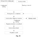
- S1. performing a drying process, and running a fresh air device at intervals during the drying process;
- S11. turning on a drying device to dry laundry;
- S12. operating the fresh air device at intervals to exchange air between an interior and an outside of a washing machine cylinder;
- S 13. operating the drying device to a preset time, and ending the drying process;
- S2. turning off the drying device after the drying process is completed, and turning on the fresh air device to perform fragrance treatment on laundry until the process is completed.
- S21. turning on a fresh air fan exchange air be
- tween the interior and the outside of the washing machine cylinder, and setting a fragrance agent at a fresh air inlet or turning on a fragrance device to blow fragrance into the washing machine cylinder through a circulating air;
- S22. performing fragrance treatment on laundry in the washing machine cylinder, and turning off the fresh air fan after performing fragrance treatment to a preset time;
- S23. turning on a motor to drive the washing machine cylinder to rotate to flip laundry;
- S24. after flipping the laundry is completed, turning on the fresh air fan to further performing fragrance treatment on laundry for a preset time, and turning off the washing machine after the process is completed.
- Furthermore, the drying device in S11 includes a heater and/or a drying fan.
- Furthermore, before the drying process in S1, a washing process and/or a rinsing process are included. In the washing process and/or the rinsing process, at least one process of adding a laundry additive is included. The process of adding the laundry additive comprises: mixing the laundry additive with water to form a mixture, and spraying the mixture directly onto the surface of laundry through a spraying device in multiple times.
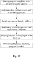
- Furthermore, when the laundry additive is added twice, the washing process and/or the rinsing process are/is performed as follows:
- S01. starting a washing machine, supplying water and a first laundry additive;
- S02. performing the washing process and/or the rinsing process;
- S03. supplying a mixture of a second laundry additive and water after the washing process and/or the rinsing process is completed;
- S04. supplying water to a set water level, and performing a softening process until the process is completed.
- Furthermore, step S01 specifically includes the following steps: supplying water in the washing machine to a set water level; heating water to generate steam flowing into an inner cylinder, and turning on a drying fan to circulate air in the inner cylinder for increasing temperature and humidity in the inner cylinder and laundry; fully mixing the first laundry additive with water at one time, spraying a mixture having the first laundry additive into the inner cylinder of the washing machine by multiple times, and rotating the inner cylinder in stopping spraying; after a spraying process is completed, supplying water to a set water level, and then performing the washing process and/or the rinsing process in keeping a water temperature.
- Furthermore, the set water level of the washing machine is above a heating pipe and lower than the surface of the inner cylinder.
- Furthermore, before step S01, the following steps are included: S00. draining water, weighing laundry after draining water out of the inner cylinder; determining the amount of water, the amount of the first laundry additive, and the amount of the second laundry additive added in the washing machine based on the weight of laundry.
- Furthermore, the water level is detected between step S01 and step S02. It is detected whether the water level reaches a set water level value by a water level sensor after the first laundry additive is added. If reaching the set water level value, a washing process is performed for the laundry. If the set water level value is not reached, water is supplied in the washing machine until the set water level value is reached. After supplying water, the washing process is performed for the laundry.
- Furthermore, the fragrance agent is placed in an inlet component of the fresh air device. The fragrance agent can be placed directly at the air inlet of a fresh air duct, or can be placed in the fragrance device placed at the air inlet of the fresh air duct.
- Furthermore, a heating device is arranged in the air inlet of the fresh air system. The heating device and the fragrance device are both arranged on the downstream from the fan. When the weather is cold or the indoor temperature is lower, the heating device and the fresh air system are started at the same time, so the ventilation efficiency is sped up and the quality and speed of the fragrance is improved, and user's experience is improved.
- In another technical solution of the present invention, a washing machine with a fresh air system is controlled by the above-mentioned method.
- Compared with the prior art, the present invention has the following advantages:
- 1. In the method for controlling a washing machine with a fresh air system of the present invention, the operation of the fresh air system runs in the drying process. Air is continuously exchanged between the interior and the outside of the washing machine cylinder during the drying process, so that steam and odors in the cylinder is removed during the drying process, and user's experience is improved.
- 2. In the present invention, it is performed to fumigate on laundry after the drying process is completed. Fragrance agent or fragrance device is directly placed into the inlet component of the fresh air system. The fresh air system runs to blow the fragrance into the cylinder to fumigate the dried laundry, so that the fragrance is remained on the laundry, and user's experience is improved.
- The specific implementations of the present invention are further described in detail below in conjunction with the accompanying drawings.
- Accompanying drawings, constituting a part of the present disclosure, are used for providing a further understanding of the present invention, schematic embodiments of the present invention and description thereof are used for explaining the present invention, and do not constitute an improper limitation on the present invention. Apparently, the accompanying drawings in the following description are only some embodiments, for those ordinarily skilled in the art, on the premise of no creative labor, other accompanying drawings can further be obtained from these accompanying drawings. In the Figures:
-
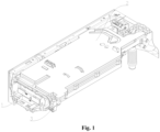
Figure 1 is a structural diagram of an additive dispensing device according to an embodiment of the present invention; -
Figure 2 is an exploded view of an additive dispensing device according to an embodiment of the present invention; -
Figure 3 is a partial enlarged view of position A inFigure 2 ; -
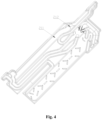
Figure 4 is a schematic diagram of an upper cover plate in an embodiment of the present invention; -
Figure 5 is a bottom view of an upper cover plate in an embodiment of the present invention; -
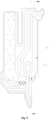
Figure 6 is a cross-sectional view in B-B direction inFigure 5 ; -
Figure 7 is a structural diagram of a lower cover plate in an embodiment of the present invention; -
Figure 8 is a structural diagram of a shielding plate in an embodiment of the present invention; -
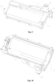
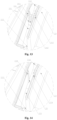
Figures 9 and 10 are structural diagrams of a water storage box at different angles according to an embodiment of the present invention; -
Figures 11 and 12 are exploded views of a water storage box at different angles according to an embodiment of the present invention; -
Figure 13 is a partial enlarged view of position C inFigure 11 ; -
Figure 14 is a partial enlarged view of position D inFigure 12 ; -
Figure 15 is a structural diagram of a cover body in an embodiment of the present invention; -
Figure 16 is a top view of a cover body in an embodiment of the present invention; -
Figure 17 is a cross-sectional view in E-E direction inFig. 16 ; -
Figure18 is a flow chart of a drying process and a fragrance treatment of a washing machine of the present invention; -
Figure 19 is a flow chart of a control method of a washing machine in an embodiment of the present invention. - Description of the main components in the
figures: 1 . Dispensing box; 11. Shielding plate; 12. Hollow portion; 2. Cover plate; 21. Upper cover plate; 211. Groove; 212. Accommodating groove; 22. Lower cover plate; 221. Groove; 222. Mounting groove; 2221. Shaft hole; 2222. Mounting hole; 23. Air inlet; 24. Air outlet; 25. Filter; 251. Filter frame; 252. Filter screen; 253. Shaft seat; 254. Support seat; 26. Mounting shaft; 261. First mounting shaft; 262, Second mounting shaft; 27. Air discharge pipe; 3. Water storage box; 31. Through hole; 32. Air outlet; 33. Boss; 331. Fluid guiding groove; 332. Fluid guiding hole; 333. Notch; 334. Gap; 34. Filter; 341. Filter frame; 342. Filter screen; 343. Positioning column; 35. Limit block; 36. Drainage port; 4. Cover body; 41. Accommodating chamber; 42. Air inlet; 43, Fluid guiding groove; 431. Fluid guiding wall. - It should be noted that these drawings and the description are not intended to limit the scope of the present invention in any way, but rather to illustrate the concept of the present invention for those skilled in the art by referring to specific embodiments.
- In order to make objects, technical solutions and advantages of the embodiments of the present invention clearer, the solutions in the embodiments are clearly and completely described as follows in combination with accompanying drawings in the embodiments of the present invention. The following embodiments are used for illustrating the present invention, rather than limiting the scope of the present invention.
- In the description of the present invention, it should be noted that, the orientation or positional relationship indicated by such terms as "up", "down", "front", "rear", "left", "right", "vertical", "inner" and "outer" is the orientation or positional relationship based on the accompanying drawings. Such terms are merely used for conveniently and simplified describing the present invention, rather than indicating or implying that the device or element referred to must be located in a certain orientation or must be constructed or operated in a certain orientation. Therefore, the terms cannot be understood as a limitation to the present invention.
- In the description of the present invention, it should be noted that, unless otherwise stipulated and defined definitely, such terms as "installed", "connected" and "in connection" should be understood in their broad sense, e.g., the connection can be a fixed connection, a detachable connection or an integral connection; can be mechanical connection or electrical connection; and can be direct connection or can be indirect connection through an intermediate. For those skilled in the art, specific meanings of the above terms in the present invention can be understood according to specific conditions.
- As shown in
Figures 1 to 8 , an additive dispensing device of the present invention includes a dispensing box 1 and acover plate 2 installed on a top of the dispensing box 1. A hollow chamber is formed inside thecover plate 2, an air duct is provided inside the hollow chamber, one end of the air duct is connected with the inside of the dispensing box 1, and the other end is connected with the outside of the dispensing box 1. - Through the above-mentioned additive dispensing device, the external atmosphere flows into the air duct through the dispensing box 1, and then fresh air flows into an interior of the laundry treatment cylinder through the air duct. Or the air inside the laundry treatment cylinder flows into an interior of the dispensing box 1 through the air duct, and then is discharged to the outside through the dispensing box 1. Thereby it is achieved to exchange air between the interior of the laundry treatment cylinder and the outside, to remove odors inside the laundry treatment cylinder and improve user's experience.
- As shown in
Figure 2 andFigures 3 to 7 , an additive dispensing device is provided in an embodiment of the present invention. An air duct has anair inlet 23 and anair outlet 24, theair inlet 23 of the air duct is connected with an interior of the dispensing box 1, and theair outlet 24 of the air duct is connected with the outside of the dispensing box 1. - In the embodiment, the
air inlet 23 of the air duct is connected with the interior of the dispensing box 1, so that the air duct is connected with the external atmosphere. The external atmosphere flows into the air duct through theair inlet 23, and fresh air flows into the interior of the laundry treatment apparatus through theair outlet 24 to replace air inside the laundry treatment apparatus. - As shown in
Figures 2 to 7 , in the embodiment, thecover plate 2 includes anupper cover plate 21 and alower cover plate 22 that are interlocked. Theupper cover plate 21 and thelower cover plate 22 are both provided with grooves with openings arranged opposite to each other. Thegroove 211 of theupper cover plate 21 and thegroove 221 of thelower cover plate 22 cooperate with each other to close the openings to form the air duct, and theair inlet 23 and theair outlet 24 are provided at a bottom of thegroove 221 of thelower cover plate 22. - In the embodiment, the
upper cover plate 21 and thelower cover plate 22 are buckled together to form a hollow chamber, and a water inlet passage is provided inside the hollow chamber for feeding water into the dispensing box 1. The air duct is closed to prevent the air in the air duct from flowing into the water inlet passage. - As shown in
Figures 2 ,3 and7 , in the embodiment, a filter 25 is installed inside the air duct. The filter 25 is inserted into the air duct between theair inlet 23 and theair outlet 24. The filter 25 is detachably installed on theupper cover plate 21 and/or thelower cover plate 22 via a rotating shaft. - In the embodiment, a filter 25 is installed inside the air duct for filtering the external air flowing into the air duct, to prevent impurities such as dust and lint in the external air from entering the interior of the laundry treatment cylinder through the
air outlet 24 of the air duct to cause to contaminate the interior of the laundry treatment cylinder. - As shown in
Figures 2 ,3 and7 , in the embodiment, thegroove 221 of thelower cover plate 22 includes a first side wall and a second side wall that are opposite to each other. The filter 25 includes afilter frame 251 and afilter screen 252 installed on thefilter frame 251. Two ends of thefilter frame 251 are in contact with the first side wall and the second side wall of thegroove 221 of thelower cover plate 22, and a top of thefilter frame 251 is in contact with the upper surface of theupper cover plate 21. - In the embodiment, the
filter frame 251 is in contact with theupper cover plate 21 and thelower cover plate 22, so that the air inside the air duct flows into the laundry treatment cylinder after being filtered by the filter 25, preventing impurities such as dust and lint in the external atmosphere from contaminating the laundry treatment cylinder and the laundry inside. - Preferably, the
filter screen 252 is perpendicular to an air flow direction inside the air duct, thereby increasing the contact area between thefilter screen 252 and air and enhancing the filtering effect. - As shown in
Figures 4 to 6 , in the embodiment, a bottom of thegroove 221 of thelower cover plate 22 is recessed downward to form a mounting groove 222 of which an upper end is an opening. Ashaft seat 253 is provided at a lower end of thefilter frame 251. Shaft holes are respectively provided on theshaft seat 253 and side walls of the mounting groove 222 for allowing the mounting shaft 26 to pass through to connect the filter 25 with thelower cover plate 22. - In the embodiment, the filter 25 is installed on the
upper cover plate 21 and/or thelower cover plate 22 via a rotating shaft. The filter 25 is detachably connected with and thecover plate 2, so users can remove or install the filter 25 by themselves, and it is convenient for the user to clean or replace the filter 25, further enhancing the user's favorability. - As shown in
Figures 2 and3 , in the embodiment, a bottom end of theshaft seat 253 is embedded in the mounting groove 222 and is in contact with the bottom of the mounting groove 222, so that the filter 25 can fully filter the air inside the air duct. - As shown in
Figures 2 and3 , in the embodiment, the mounting groove 222 has two side walls that are opposite to each other, and the two ends of theshaft seat 253 are detachably fixedly connected to the side walls of the mounting groove 222 being opposite to each other via the rotating shaft. - In the embodiment,
shaft holes 2221 are formed on the side walls of the mounting groove 222, and includes a first shaft hole and a second shaft hole respectively arranged on the two side walls of the mounting groove 222. A first mounting shaft 261 and asecond mounting shaft 262 are respectively arranged at both ends of theshaft seat 253 to pass through the first shaft hole and the second shaft hole respectively. - Preferably, the first mounting shaft 261 is integrated with the
shaft seat 253, and the second mountingshaft 262 is movably connected with theshaft seat 253. The first mounting shaft 261 is fixed to thelower cover plate 22, and the second mountingshaft 262 is detachably connected to thelower cover plate 22, so that the filter 25 is detachably mounted on thelower cover plate 22. - As shown in
Figure 3 , in the embodiment, the filter 25 also includes a support seat 254 extending downward from the bottom end of thefilter frame 251, and a mounting hole 2222 is provided on the bottom of the mounting groove 222 for the support seat 254 to be inserted in. The support seat 254 passes through the mounting hole 2222 and is placed between the dispensing box 1 and thelower cover plate 22. - In the embodiment, by the arrangement of the support seat 254, it is convenient for user to disassemble or install the filter 25, thereby improving the assembly efficiency of the filter 25, and facilitating user to clean or replace the filter 25.
- As shown in
Figures 4 to 6 , in the embodiment, part of the upper surface of theupper cover plate 21 is recessed upward to form anaccommodating groove 212 of which a lower end is an opening. The upper of thefilter frame 251 is inserted into theaccommodating groove 212 and in contact with side walls and a bottom of theaccommodating groove 212. - In the embodiment, the
filter frame 251 is in contact with the side walls and the bottom of theaccommodating groove 212 to ensure that the air inside the air duct flows into the interior of the laundry treatment cylinder after being fully filtered by the filter 25. - As shown in
Figures 2 to 7 , in the embodiment, theupper cover plate 21 is provided with a groove opening downward, and thegroove 211 of theupper cover plate 21 and thegroove 221 of thelower cover plate 22 cooperate with each other to close the opening to form an air duct. Thegroove 211 of theupper cover plate 21 includes a first side wall and a second side wall being opposite to each other, and both ends of thefilter frame 251 are in contact with the first side wall and the second side wall of thegroove 211 of theupper cover plate 21, and theaccommodating groove 212 is formed at the bottom of thegroove 211 of theupper cover plate 21, so that the upper of thefilter frame 251 is embedded in thegroove 211 of theupper cover plate 21 and partially embedded in theaccommodating groove 212, thereby improving the sealing property of the air duct and fully filtering the air inside the air duct. - Through the above-mentioned additive dispensing device, the filter 25 filters the external air flowing into the air duct, preventing impurities such as dust and lint in the external atmosphere from entering the interior of the laundry treatment cylinder through the
air outlet 24 of the air duct and contaminating the interior of the laundry treatment cylinder. The filter 25 is installed on theupper cover plate 21 and/or thelower cover plate 22 via a rotating shaft, so that user can remove or install the filter 25 by himself, and it is convenient for cleaning or replacing the filter 25. - The difference between the embodiment and the embodiment 1 is that: the
cover plate 2 includes anupper cover plate 21 and alower cover plate 22 that are buckled together. Thelower cover plate 22 is provided with a groove with an opening upward, and a side of theupper cover plate 21 being in contact with thelower cover plate 22 is a plane. Surfaces of the side walls of thegroove 221 of thelower cover plate 22 facing theupper cover plate 21 are correspondingly in contact with the plane of theupper cover plate 21 to close the opening of the groove to form an air duct. A bottom of thegroove 221 of thelower cover plate 22 is provided with anair inlet 23 and anair outlet 24. - In the embodiment, the
groove 221 of thelower cover plate 22 is in contact with the surface of theupper cover plate 21 to form an air duct. So it is facilitated to assemble thelower cover plate 22 with theupper cover plate 21, reduce the difficulty of assembly, and ensure the tightness of the air duct. - In the embodiment, part of the upper surface of the
upper cover plate 21 is recessed upward to form anaccommodating groove 212 of which a lower end is an opening. The upper of thefilter frame 251 is inserted into theaccommodating groove 212 and in contact with the side walls and the bottom of theaccommodating groove 212, so that the air in the air duct can be filtered by thefilter screen 252 and then flow to theair outlet 24 of the air duct. - Through the above-mentioned additive dispensing device, the
groove 221 of thelower cover plate 22 is in contact with the surface of theupper cover plate 21 to form an air duct, so the difficulty of assembling theupper cover plate 21 and thelower cover plate 22 is reduced. The upper of thefilter frame 251 is embedded in theaccommodating groove 212 to improve the sealing performance of the air duct, so that the air in the air duct can be fully filtered. - As shown in
Figures 2 and8 , the embodiment is further described based onembodiments 1 and 2. At least one dispensing chamber is provided in an interior of the dispensing box 1. Part of the opening of the dispensing chamber is covered with a shieldingplate 11. Ahollow portion 12 is formed on the shieldingplate 11. Thehollow portion 12 is arranged correspondingly to theair inlet 23 of the air duct in up and down direction. - In the above-mentioned additive dispensing device, the
hollow portion 12 on the shieldingplate 11 is arranged correspondingly to theair inlet 23 of the air duct, so that the aromatic substances generated by volatilizing the fragrance agent pass through thehollow portion 12 and flow into the air duct. Thereby the laundry treatment cylinder and the laundry inside are fumigated, and odorous substances inside the laundry treatment cylinder is quickly removed. - As shown in
Figure 1 andFigures 9 to 17 , an additive dispensing device is provided in the embodiment of the present invention, which includes awater storage box 3 with a hollow inside. An air duct is provided at a bottom of thewater storage box 3, one end of the air duct is connected with the interior of thewater storage box 3, and the other end of the air duct is connected with the outside of thewater storage box 3. - In the embodiment, the external air flows into the air duct through the
water storage box 3. Fresh air can flow into the interior of the laundry treatment cylinder through the air duct, or the air inside the laundry treatment cylinder flows into thewater storage box 3 through the air duct, so the air inside the laundry treatment cylinder is discharged to the outside. It is achieved to exchange air between the interior of the laundry treatment cylinder and the external atmosphere, to remove odors inside the laundry treatment cylinder, and further to improve user's experience. - The air duct has an
air inlet 42 connected with the outside of thewater storage box 3, a throughhole 31 is provided at the bottom of thewater storage box 3, and theair inlet 42 of the air duct is connected with the interior thewater storage box 3 through the throughhole 31. Anair outlet 32 connected with the interior of thewater storage box 3 is provided on a side wall of thewater storage box 3. - As shown in
Figures 9 and11 , in the embodiment, acover body 4 is arranged on the bottom of thewater storage box 3. Anaccommodating chamber 41 of which a top end is an opening is formed inside thecover body 4, and thewater storage box 3 and thecover body 4 cooperate with each other to close the opening of theaccommodating chamber 41 to form an air duct. Theair inlet 42 of the air duct is provided at one end of thecover body 4. - In the embodiment, the
water storage box 3 and thecover body 4 cooperate with each other to close the opening of theaccommodating chamber 41 to form an air duct, so that the air duct is in a closed state from the external atmosphere, thereby preventing the air flowing into the air duct from leaking to cause the odor substances inside the laundry treatment cylinder to spread and to affect user's experience. - As shown in
Figure 15 , in the embodiment, theaccommodating chamber 41 is in the shape of an inverted cone or an inverted frustum, of which radial dimensions are gradually narrowed from top to bottom, and theair inlet 42 of the air duct is arranged at the lowest point of the inverted cone or the inverted frustum. - In the embodiment, the
air inlet 42 of the air duct is arranged at the lowest point of the inverted cone or the inverted frustum, so that the air in the laundry treatment cylinder flows upward quickly after flowing into the air duct through theair inlet 42, and then flows into thewater storage box 3 through the throughhole 31 formed on the bottom of thewater storage box 3, and finally discharged to the outside through theair outlet 32 on the side wall of thewater storage box 3. - Preferably, the
accommodating chamber 41 formed inside thecover body 4 is an inverted isosceles triangle with left and right sides gradually tilted toward the center, and theair inlet 42 is arranged at the lowest point of the inverted isosceles triangle, so that the air flowing into the air duct from the laundry treatment cylinder forms a vortex airflow at theair inlet 42, and the air quickly flows to the throughhole 31. It is avoided that air is accumulated at the bottom of theaccommodating chamber 41. - As shown in
Figures 15 to 17 , in the embodiment, the bottom wall of theaccommodating chamber 41 is recessed downward near theair inlet 42 of the air duct to form afluid guiding groove 43, and thefluid guiding groove 43 has afluid guiding wall 431 being opposite to theair inlet 42 of the air duct. Thefluid guiding wall 431 is extended upwardly and obliquely in a direction away from theair inlet 42 of the air duct. - In the embodiment, the
fluid guiding wall 431 of afluid guiding groove 331 extends upwardly and obliquely in a direction away from theair inlet 42 of the air duct, that is, thefluid guiding wall 431 of thefluid guiding groove 331 is extended obliquely in a direction of the air flow inside the air duct, so that the air inside the laundry treatment cylinder flows upward along a first side of thefluid guiding groove 331. It is avoided that air is accumulated at the bottom of the air duct, especially odor substances is accumulated at the bottom of the air duct and unable to be discharged to the outside. - In the present embodiment, both the bottom of the
water storage box 3 and the interior of thecover body 4 form an accommodating chamber with openings arranged opposite to each other. The accommodating chamber at the bottom of thewater storage box 3 and theaccommodating chamber 41 inside thecover body 4 cooperate with each other to close the openings to form an air duct, thereby increasing the space above the air duct. The air inside the laundry treatment cylinder can quickly flows into the air duct, and flows upward through the throughhole 31 at the bottom of thewater storage box 3 to flow into the interior of thewater storage box 3. - Alternatively, an
accommodating chamber 41 with an opening upward is formed inside thecover body 4, and a side of thewater storage box 3 facing thecover body 4 is a plate. Edge of the opening of the accommodating chamber formed inside thecover body 4 is bent outward to form a circle of flange, and the flange is in contact with a side of thewater storage box 3 facing thecover body 4 to close the opening of theaccommodating chamber 41 to form an air duct. So it is easy to assemble thewater storage box 3 and thecover body 4 and the sealing performance of the air duct is ensured. - As shown in
Figures 9 and11 , in the embodiment, the air duct is extended from a front end of the bottom of thewater storage box 3 to a rear end of the bottom of thewater storage box 3 to form a long strip of air duct extending in a length direction of thewater storage box 3, so that the air inside the air duct flows from front to back, and finally is discharged to the outside. It is avoided that user catches the odorous substances in the air and feel discomfort. - As shown in
Figures 9 and11 , in the embodiment, theair inlet 42, the throughhole 31 and theair outlet 32 are arranged in sequence from front to back. An axis of theair outlet 32 is higher than an axis of theair inlet 42, so it is conducive that odorous substances with a smaller density than air inside the air duct quickly flows toward theair outlet 32 at the rear end. - As shown in
Figures 15 to 17 , in the embodiment, the radial dimensions of theaccommodating chamber 41 formed inside thecover body 4 are gradually increased from front to back to prevent the air from accumulating above the throughhole 31 to cause excessive local pressure in the air duct. - Through the above-mentioned additive dispensing device, the interior of the laundry treatment cylinder is communicated with the interior of the
water storage box 3 through the air duct, so that the air in the laundry treatment cylinder flows into the interior of thewater storage box 3 through the air duct, and is then discharged to the outside through theair outlet 32 on the side wall of thewater storage box 3. Thereby odorous substances inside the laundry treatment cylinder are quickly discharged. - As shown in
Figure 10 andFigures 12 to 14 , the embodiment is further described based onembodiment 4. An interior of awater storage box 3 is provided with aboss 33 protruding and extending upwardly. Part of a top of theboss 33 is recessed downward to form afluid guiding groove 331, a side wall of thewater storage box 3 is provided with anair outlet 32, and the side wall of thefluid guiding groove 331 is provided with afluid guiding hole 332 connected with theair outlet 32. - In the embodiment, the air inside the air duct flows into the
water storage box 3 through the throughhole 31. The air inside thewater storage box 3 flows toward thefluid guiding hole 332 on the side wall of thefluid guiding groove 331, and finally discharged into the outside through theair outlet 32, thereby realizing ventilation of the laundry treatment cylinder. - As shown in
Figure 10 andFigures 12 to 14 , in the embodiment, thefluid guiding groove 331 is a pressed groove with anotch 333, and the air duct is connected with thefluid guiding groove 331 through thenotch 333. Thenotch 333 and thefluid guiding hole 332 are arranged at both ends of thefluid guiding groove 331 and opposite to each other, and the bottom of thefluid guiding groove 331 is an inclined surface extending upward. - In the embodiment, the air inside the
water storage box 3 flows into thefluid guiding groove 331 through thenotch 333. The bottom of thefluid guiding groove 331 is an inclined surface extending upward, so the air flows upward along the bottom of thedrainage groove 331, especially odorous substances with lower density are quickly discharged out through thefluid guiding hole 332. - As shown in
Figure 10 andFigures 12 to 14 , in the embodiment, afilter 34 is provided in thefluid guiding groove 331, and thefilter 34 is detachably mounted on the side walls of thefluid guiding groove 331 via a rotating shaft. - In the embodiment, the
filter 34 is installed on the side walls of thefluid guiding groove 331 via the rotating shaft, so that thefilter 34 can be detachably connected with the side walls of thefluid guiding groove 331. It is convenient for users to replace or regularly clean thefilter 34. Thefilter 34 is used for filtering the air flowing into thewater storage box 3 through the air duct, so impurities such as dust and lint in the air is prevented from clogging thefluid guiding hole 332 to cause the air inside the laundry treatment cylinder to be unable to be discharged through the air duct. - As shown in
Figure 10 andFigures 12 to 14 , in the embodiment, thefilter 34 includes afilter frame 341 and afilter screen 342 installed on thefilter frame 341. Two side ends of thefilter frame 341 are respectively in contact with the side walls of thefluid guiding groove 331 being opposite to each other, and a bottom end of thefilter frame 341 is in contact with a bottom of thefluid guiding groove 331. The air is filtered through thefilter screen 342 to prevent air from flowing out from the two side ends of thefilter frame 341 to block thefluid guiding hole 332. - As shown in
Figures 10 and13 , in the embodiment, two side ends of thefilter frame 341 are respectively provided with apositioning columns 343 extending toward the corresponding side wall of thefluid guiding groove 331. The side walls of thefluid guiding groove 331 are respectively provided with anotch 334 for installing thepositioning columns 343 on the corresponding side walls, so that thefilter 34 can be detachably installed on the side walls of thefluid guiding groove 331. - As shown in
Figures 12 and14 , in the embodiment, alimit block 35 abutting against thefilter 34 is provided in thefluid guiding groove 331. Thefilter 34 and thelimit block 35 are arranged in sequence in a direction of the air flow, so that thefilter 34 is firmly installed in thefluid guiding groove 331 to prevent thefilter 34 from becoming loose due to the action of the air flow. - Through the above additive dispensing device, the
filter 34 is detachably installed on the side walls of thefluid guiding groove 331 via the rotating shaft, so it is convenient for user to replace or clean thefilter 34. In addition thefilter 34 is used for filtering the air flowing into thewater storage box 3 from the air duct to prevent impurities such as dust and lint in the air from clogging thefluid guiding hole 332. - A laundry treatment apparatus in an embodiment of the present invention includes a laundry treatment cylinder and the additive dispensing device described in any one of Embodiments 1 to 3, and one end of the air duct is connected with the interior of the laundry treatment cylinder.
- In the embodiment, an
air inlet 23 of the air duct is connected with an interior of the dispensing box 1, and anair outlet 24 of the air duct is connected with an interior of the laundry treatment cylinder via anair discharge pipe 27. The external air flows into the air duct through the dispensing box 1, and the air inside the air duct is filtered by the filter 25 and then flows into the interior of the laundry treatment cylinder, thereby realizing to exchange air between the external atmosphere and the interior of the laundry treatment cylinder, and removing odor substances inside the laundry treatment cylinder. - As shown in
Figures 1 and2 , the additive dispensing apparatus also includes awater storage box 3. The dispensing box 1 can be extractably arranged inside thewater storage box 3. Acover plate 2 is arranged on the top of thewater storage box 3. A hollow chamber is formed inside thecover plate 2. A water inlet passage is provided inside the hollow chamber for feeding water into the dispensing box 1. The air duct is closed on one side of the water inlet passage to prevent the air in the air duct from flowing into the water inlet passage. - In the embodiment, a
hollow portion 12 is formed on a shieldingplate 11, and thehollow portion 12 is arranged correspondingly to theair inlet 23 of the air duct in up and down direction, so that the aromatic substances generated by volatilizing the fragrance agent pass through thehollow portion 12 and flow into the air duct, and then flow the interior of the laundry treatment cylinder. Thereby odorous substances inside the laundry treatment cylinder are quickly removed, and the laundry is fumigated. - Through the above laundry treatment apparatus, the air duct is connected with the external atmosphere. The external air flows into the air duct through the
air inlet 23, and fresh air flows into the interior of the laundry treatment apparatus through theair outlet 24 to replace the air inside the laundry treatment apparatus, to remove odor inside the laundry treatment apparatus and improve user's experience. - A laundry treatment apparatus in an embodiment of the present invention, includes a laundry treatment cylinder and the additive dispensing device described in any one of
Embodiment 4 and Embodiment 5. One end of the air duct is connected with an interior of the laundry treatment cylinder. - In the embodiment, an
air inlet 42 of the air duct is connected with the interior of the laundry treatment cylinder, and the air duct is connected with an interior of thewater storage box 3 through a throughhole 31. A side wall of thewater storage box 3 is provided with anair outlet 32 connected with the interior of thewater storage box 3, so that the air inside the laundry treatment cylinder is driven to flow into the air duct by a driving component, flow into the interior of thewater storage box 3, and then be discharged to the outside through theair outlet 32. - As shown in
Figure 1 , in the embodiment, the additive dispensing apparatus includes a dispensing box 1 that can be extractably arranged in thewater storage box 3. At least one dispensing chamber is formed in the dispensing box 1. Acover plate 2 is installed on a top of the dispensing box 1. A hollow chamber is formed inside thecover plate 2. A water inlet passage for feeding water to the dispensing chamber is provided in the hollow chamber. The dispensing chamber is connected with the interior of thewater storage box 3, and adrainage port 36 connected with the laundry treatment cylinder is provided at the bottom of thewater storage box 3. - Through the above laundry treatment apparatus, the interior of the laundry treatment cylinder is connected with the
air inlet 42 of the air duct, and the air duct is connected with theair outlet 32 on the side wall of thewater storage box 3, so that the air inside the laundry treatment cylinder flows into the air duct and is discharged to the outside through theair outlet 32, thereby realizing to exchange air between the interior of the laundry treatment cylinder and the external atmosphere. - As shown in
Figure 18 andFigure 19 , a method for controlling a washing machine with a fresh air system comprises the following steps: - S01. starting a washing machine, supplying water and a first laundry additive;
- S02. performing a washing process and/or a rinsing process;
- S03. supplying a mixture of a second laundry additive and water after the washing process and/or the rinsing process is completed;
- S04. supplying water to a set water level, and performing a softening process until the process is completed;
- S1. executing a drying process, and running a fresh air device at intervals during the drying process;
- S2. turning off a drying device after the drying process is completed, and turning on the fresh air device to perform fragrance treatment on laundry until the process is completed.
- The S1 specifically includes the following steps:
-
S 11. turning on the drying device to dry the laundry, wherein the drying device includes a heater and/or a drying fan; - S12. operating the fresh air device at intervals to exchange air between an interior and an outside of a washing machine cylinder;
- S13. operating the drying device to a preset time, automatically turning off the drying device and the fresh air device, and ending the drying process.
- The S2 specifically includes the following steps:
- S21. turning on a fresh air fan to exchange the air between the interior and the outside the washing machine cylinder, and setting a fragrance agent at a fresh air inlet or turning on a fragrance device to blow the fragrance into the washing machine cylinder through a circulating air;
- S22. performing fragrance treatment on the laundry in the washing machine cylinder, and turning off the fresh air fan after performing fragrance treatment to a preset time;
- S23. turning on a motor to drive the washing machine cylinder to rotate to flip the laundry;
- S24. after flipping the laundry is completed, turning on the fresh air fan to further performing fragrance treatment on the laundry for a preset time, and turning off the washing machine after the process is completed.
- It should be noted that a water level sensor is used for detecting the water level after step S01 ends and before step S02 is executed. It is detected whether the water level reaches a set water level value. If reaching the set water level value, a washing process is performed for the laundry. If the set water level value is not reached, water is supplied in the washing machine until the set water level value is reached. After supplying water, the washing process is performed for the laundry.
- The fragrance agent used in the present application is in solid state or liquid state. The solid fragrance agent can be directly placed at the air inlet of the fresh air duct, or can be placed in a fragrance device placed at the air inlet of the fresh air duct. The liquid fragrance agent can be placed in the fragrance device placed at the air inlet of the fresh air duct.
- The fragrance device may include a box body used for holding the liquid fragrance or the solid fragrance and a cover body. The cover body is detachably connected to the box body. The fragrance device may be replaced by a groove arranged on an inner wall of the air inlet of the washing machine.
- It should be noted that any skilled person in the field can also arrange a heating device in the air inlet of the fresh air system, and the heating device and the fragrance device are both arranged on the downstream from the fan. When the weather is cold or the indoor temperature is lower, the fan of the fresh air system runs and the heating device can be started for heating, so the ventilation efficiency is sped up and the quality and speed of the fragrance is improved, and user's experience is improved. Similarly, any skilled person in the field can derive similar technical solutions according to actual needs, but all adaptive improvements and arrangements made based on the embodiment are within the scope of the present invention.
- In the embodiment, by adding the operation of the fresh air system in the drying process, the air is continuously exchanged between the interior and the outside of the cylinder of the washing machine during the drying process, thereby eliminating the steam in the inner cylinder during the drying process and eliminating the odor in the laundry or the interior of the inner cylinder during the drying process. The odor is eliminated in drying process, and user's experience is improved. The fragrance treatment is executed, so the laundry is dried and enhanced the fragrance by the fresh air system without the need to arrange a structure for allowing the fragrance to enter the cylinder, thereby making more full use of the fresh air system. The fragrance flows in the cylinder by utilizing the fresh air system. The structure and the controlling process of the laundry treatment apparatus are simplified, and the laundry treatment apparatus is easily used.
- A washing machine is controlled by the above method with a fresh air system.
- This embodiment describes a method for controlling a washing machine with a fresh air system. The method is different from that of the above embodiments.
- The S01 specifically includes the following steps:
- powering on a solenoid valve, and supplying water in the washing machine to a set water level;
- heating water and generating steam by a heating device, steam flowing into an inner cylinder;
- a motor driving the inner cylinder to rotate at a speed close to the cylinder wall;
- turning on a drying fan to circulate air in the inner cylinder for increasing the temperature and humidity in the inner cylinder and the laundry, and heating the laundry to a preset temperature.
- Specifically, the set water level of the washing machine is above the heating device to prevent the heating device from running without the load, and the water level is lower than the surface of the inner cylinder. It can be understood that a small amount of water can be heat to quickly increase the temperature and generate the steam. In the process of rotating the inner cylinder, it is increased in the temperature of the laundry, so the activity of stains on the laundry is increased to improve the cleaning effect.
- It should be further described that the heating device is arranged between the inner cylinder and the outer cylinder, and on an inner wall of a bottom of the outer cylinder. Any skilled person in the field can also arrange a steam generating device between the inner cylinder and the outer cylinder to accelerate the generation of steam and speed up the entire washing process.
- In the embodiment, the laundry is wetted by the heating steam and in a drying and circulating mode, so the temperature and humidity of the laundry are increased, and the activity of the detergent is improved in a washing process. A mixed solution containing the detergent is sprayed directly onto the laundry to increase the contact area between the detergent and the laundry, and the amount of detergent and the amount of water used are reduced.
- A washing machine with a fresh air system is controlled by the above method.
- The embodiment describes a method for controlling a washing machine with a fresh air system. The method is different from that of the above embodiments.
- The method for adding a first laundry additive in step S01 and a second laundry additive in step S03 is: mixing the first laundry additive or the second laundry additive with water to obtain a mixture, and spraying the mixture directly onto the surface of laundry through a spraying device. During the adding process, the interior of the cylinder and the laundry are maintained at the temperature and humidity set in step S12. The solution containing the laundry additive is circularly sprayed in the rotation of the inner cylinder until adding the solution containing the laundry additive is completed.
- Specifically, when the inner cylinder stops rotating, the first laundry additive or the second laundry additive is mixed with water in a mixing water passage component to form a mixture, the mixture is sprayed onto the surface of the laundry through the spraying device for a spraying time of preferably in a range of 5-15 seconds. The spraying process is stopped, and the motor drives the inner cylinder to rotate for a rotation time of preferably 8-15 seconds. The spraying process and the process of driving the inner cylinder to rotate by the motor are performed circularly, until spraying of the mixture is completed and it is measured that a set water level is reached.
- It should be noted that the first laundry additive is a detergent, and the second laundry additive is one of a softener, a laundry bactericide, a cleaning agent, etc. Taking the softener as an example, it can be understood that the detergent is generally added before adding the softener. Herein, both the detergent and the softener being in a mixture with water can be directly sprayed on the surface of the laundry, so that the detergent is in direct contact with the surface of the laundry, especially with the stains on the surface of the laundry, under a high temperature and high humidity environment. It can be simultaneously improved the activity of the detergent and the stains, and reduced the amount of detergent and the amount of water.
- It should be further described that the spraying device includes a mixing water passage component and a spraying head. The mixing water passage component includes a mixer, a main water passage and a branch water passage, the washing water flows the mixer through the main water passage. The detergent flows into the main water passage through the branch water passage before flowing in the mixer. The opening and closing of the main water passage and the branch water passage can be controlled by a solenoid valve respectively. There is no need of adding a pressure pump in the mixing water passage component in the embodiment, and the detergent is directly flushed into the mixer and mixed with water by the inflowing pressure. The structure of the mixing water passage component is simple and occupies the small internal space of the washing machine. Water and electricity are saved by using the mixing water passage component. The installation modes of the spraying head can be selected as upright, pendant, side wall, ceiling and other types. Users can choose an installation mode according to specific needs.
- In the embodiment, in the spraying process, a mixture of high-concentration laundry additive is directly sprayed onto the surface of laundry, thereby increasing the contact area between the laundry additive and the laundry, reducing the amount of the laundry additive, and further reducing the generation of excessive washing foam. The amount of foam residue in the inner cylinder and window pad of the washing machine is reduced after the washing is completed. By increasing the temperature and humidity on the surface of the laundry during the spraying process, the performance of water dissolving stains can be improved, and the activity of the laundry additive is improved.
- A washing machine is controlled to run by the method with a fresh air system.
- The embodiment describes a method for controlling a washing machine with a fresh air system. The method is different from the above embodiments as follows.
- S02. washing and rinsing process: continuously heating by a heating device for maintaining the water temperature at a preset value, and performing simultaneously washing for a preferred preset temperature of 30°C-60°C, which is determined according to material and degree of dirtiness of the laundry to be washed; the washing machine performing draining water and dewatering when a washing time reaches a preset value; after performing dewatering, performing the rinsing process and opening separately the solenoid valve of the main water passage, spraying water onto the laundry to rinse the laundry. After performing the rinsing process, the water is drained and the laundry is dewatered. Preferably, the rinsing process is repeatedly performed for 1 to 3 times. It is predicted that the laundry with special materials cannot be dewatered, and the dewatering step can be controlled to not be performed by selecting the washing mode.
- S04. softening process: softening the laundry after the softener is sprayed on the laundry; when the inner cylinder performs rotating to a preset value, spraying water on the laundry to wash away the residual foam. There is no need to rinse the softener. After performing the rinsing process, the washing machine performs draining and dewatering.
- In the embodiment, during the process of washing and softening the laundry, the washing water is sprayed to be in fully contact with the laundry. Compared with the traditional mode of feeding water, the method has advantages of saving water and electricity.
- According to experimental test, compared with the traditional washing method, the method of the embodiment can reduce the water consumption of a washing machine for a single washing by 25% and the power consumption by 75%.
- A washing machine is controlled to run by the method with a fresh air system.
- The above embodiments are merely exemplary embodiments of the present invention and are not intended to limit the present invention. The protection scope of the present invention is defined by the claims. Those skilled in the art may make various modifications or equivalent solutions to the present invention within the scope of the present invention, and such modifications or equivalent solutions shall also be deemed to fall within the scope of the present invention.
Claims (30)
- An additive dispensing device, comprising, a dispensing box, wherein a cover plate is installed on a top of the dispensing box,
characterized in that, a hollow chamber is formed inside the cover plate, an air duct is provided inside the hollow chamber, one end of the air duct is connected with an interior of the dispensing box, and another end is connected with the outside of the dispensing box. - The additive dispensing device according to claim 1, characterized in that, the air duct has an air inlet and an air outlet, the air inlet of the air duct is connected with the interior of the dispensing box, and the air outlet of the air duct is connected with the outside of the dispensing box.
- The additive dispensing device according to claim 2, characterized in that, the cover plate includes an upper cover plate and a lower cover plate that are interlocked, and both the upper cover plate and the lower cover plate are provided with grooves with openings arranged opposite to each other, the groove of the upper cover plate and the groove of the lower cover plate are configured to cooperate with each other to close the openings to form the air duct, and the air inlet and the air outlet are provided at a bottom of the groove of the lower cover plate.
- The additive dispensing device according to claim 2, characterized in that, the cover plate includes an upper cover plate and a lower cover plate that are interlocked with each other,
the lower cover plate is provided with a groove opening upward, a side of the upper cover plate facing and being in contact with the lower cover plate is a plane, a surface of a side wall of the groove of the lower cover plate facing the upper cover plate is correspondingly in contact with the plane of the upper cover plate to close the opening of the groove to form the air duct, and a bottom of the groove of the lower cover plate is provided with the air inlet and the air outlet. - The additive dispensing device according to claim 3 or 4, characterized in that, a filter is installed inside the air duct, and the filter is inserted into the air duct between the air inlet and the air outlet, and
the filter is detachably installed on the upper cover plate and/or the lower cover plate via a rotating shaft. - The additive dispensing device according to claim 5, characterized in that, the groove of the lower cover plate includes a first side wall and a second side wall arranged opposite to each other,
the filter includes a filter frame and a filter screen installed on the filter frame, two ends of the filter frame are in contact with the first side wall and the second side wall of the groove of the lower cover plate, and a top of the filter frame is in contact with an upper surface of the upper cover plate. - The additive dispensing device according to claim 6, characterized in that, a part of the upper surface of the upper cover plate is recessed upward to form an accommodating groove of which a lower end is an opening, and an upper of the filter frame is inserted into the accommodating groove and in contact with side walls and a bottom of the accommodating groove.
- The additive dispensing device according to claim 7, characterized in that, the upper cover plate is provided with a groove opening downward, and the groove of the upper cover plate and the groove of the lower cover plate are configured to cooperate with each other to close the openings to form the air duct, and
the groove of the upper cover plate includes a first side wall and a second side wall arranged opposite to each other, two ends of the filter frame are correspondingly in contact with the first side wall and the second side wall of the groove of the upper cover plate, and an accommodating groove is formed at a bottom of the groove of the upper cover plate. - The additive dispensing device according to any one of claims 1 to 8, characterized in that, at least one dispensing chamber is provided in an interior of the dispensing box, and a part of the opening of the dispensing chamber is covered with a shielding plate, and a hollow portion is provided on the shielding plate and arranged correspondingly to the air inlet of the air duct in up and down direction.
- A laundry treatment apparatus, comprising, a laundry treatment cylinder and the additive dispensing device according to any one of claims 1 to 9, characterized in that, one end of an air duct is connected with the interior of the laundry treatment cylinder.
- An additive dispensing device, comprising, a water storage box with a hollow inside, characterized in that, an air duct is provided at a bottom of the water storage box, one end of the air duct is connected with an interior of the water storage box, and another end of the air duct is connected with the outside of the water storage box.
- The additive dispensing device according to claim 11, characterized in that, the air duct has an air inlet connected with the outside of the water storage box, a through hole is provided at the bottom of the water storage box, and the air inlet of the air duct is connected with the interior of the water storage box through the through hole, and
an air outlet connected with the interior of the water storage box is provided on a side wall of the water storage box. - The additive dispensing device according to claim 12, characterized in that, a cover body is arranged on the bottom of the water storage box, and an accommodating chamber with an opening upward is formed inside the cover body, and
the water storage box and the cover body are configured to cooperate with each other to close the opening of the accommodating chamber to form an air duct, and an air inlet of the air duct is provided at one end of the cover body. - The additive dispensing device according to claim 13, characterized in that, the accommodating chamber is in a shape of an inverted cone or an inverted frustum with radial dimensions gradually narrowing from top to bottom, and the air inlet of the air duct is provided at a lowest point of the inverted cone or inverted frustum.
- The additive dispensing device according to claim 14, characterized in that, a bottom wall of the accommodating chamber is recessed downward near the air inlet of the air duct to form a fluid guiding groove, the fluid guiding groove has a fluid guiding wall being opposite to the air inlet of the air duct, and the fluid guiding wall is extended upwardly and obliquely in a direction away from the air inlet of the air duct.
- The additive dispensing device according to any one of claims 11 to 15, characterized in that, a boss extending upwardly is provided in and interior of the water storage box, and a part of a top of the boss is recessed downward to form a fluid guiding groove, and
the air outlet is provided on the side wall of the water storage box, and a fluid guiding hole connected with the air outlet is provided on a side wall of the fluid guiding groove. - The additive dispensing device according to claim 16, characterized in that, the fluid guiding groove is a pressed groove with a notch, the air duct is connected with the fluid guiding groove through the notch, the notch and the fluid guiding hole are arranged at both ends of the fluid guiding groove and opposite to each other, and a bottom of the fluid guiding groove is an inclined surface extending upward.
- The additive dispensing device according to claim 17, characterized in that, a filter is provided in the fluid guiding groove, and the filter is detachably mounted on side walls of the fluid guiding groove via a rotating shaft.
- The additive dispensing device according to claim 18, characterized in that, the filter includes a filter frame and a filter screen installed on the filter frame, two ends of the filter frame are respectively in contact with the side walls of the fluid guiding groove being opposite to each other, and a bottom end of the filter frame is in contact with the bottom of the fluid guiding groove.
- A laundry treatment apparatus, comprising, a laundry treatment cylinder and the additive dispensing device according to any one of claims 11 to 19, characterized in that one end of an air duct is connected with an interior of the laundry treatment cylinder.
- A method for controlling a washing machine with a fresh air system, comprising:S1. performing a drying process, and running a fresh air device at intervals during the drying process;S2. turning off a drying device after the drying process is completed, and turning on the fresh air device to perform fragrance treatment on laundry until the process is completed.
- The method for controlling a washing machine with a fresh air system according to claim 21, characterized in that, before the drying process in S 1, a washing process and/or a rinsing process are included, and
in the washing process and/or the rinsing process, at least one process of adding a laundry additive is included. - The method for controlling a washing machine with a fresh air system according to claim 22, characterized in that, the process of adding the laundry additive comprises: mixing the laundry additive with water to form a mixture, and spraying the mixture directly onto the surface of laundry through a spraying device.
- The method for controlling a washing machine with a fresh air system according to claim 22, characterized in that,
when the laundry additive is added twice, the washing process and/or the rinsing process comprises:S01. starting a washing machine, supplying water and a first laundry additive;S02. performing the washing process and/or the rinsing process;S03. supplying a mixture of a second laundry additive and water after the washing process and/or the rinsing process is completed;S04. supplying water to a set water level, and performing a softening process. - The method for controlling a washing machine with a fresh air system according to claim 24, characterized in that, step S01 comprises:supplying water in the washing machine to a set water level,heating water to generate steam flowing into an inner cylinder, and turning on a drying fan to circulate air in an inner cylinder for increasing temperature and humidity in the inner cylinder and laundry;fully mixing the first laundry additive with water at one time, spraying a mixture having the first laundry additive into the inner cylinder of the washing machine by multiple times,rotating the inner cylinder in stopping spraying, andafter a spraying process is completed, supplying water to a set water level, and then performing the washing process and/or the rinsing process in keeping a water temperature.
- The method for controlling a washing machine with a fresh air system according to claim 25, characterized in that, the set water level of the washing machine is above a heating pipe and lower than a surface of the inner cylinder.
- The method for controlling a washing machine with a fresh air system according to claim 25, comprising before step S01:
S00. draining water, weighing laundry after draining water out of the inner cylinder; determining the amount of water, the amount of the first laundry additive, and the amount of the second laundry additive added in the washing machine based on the weight of laundry. - The method for controlling a washing machine with a fresh air system according to any one of claims 21 to 27, characterized in that, step S2 comprises:S21. turning on a fresh air fan to exchange air between an interior and the outside of the washing machine cylinder, and setting a fragrance agent at a fresh air inlet or turning on a fragrance device to blow fragrance into the washing machine cylinder through a circulating air;S22. performing fragrance treatment on laundry in the washing machine cylinder, and turning off the fresh air fan after performing fragrance treatment to a preset time;S23. turning on a motor to drive the washing machine cylinder to rotate to flip laundry, and cooling laundry;S24. after flipping the laundry is completed, turning on the fresh air fan to further performing fragrance treatment on laundry for a preset time, and turning off the washing machine after the process is completed.
- The method for controlling a washing machine with a fresh air system according to claim 28, characterized in that, step S1 comprises:S 11. turning on a drying device to dry laundry;S12. operating the fresh air device at intervals to exchange air between an interior and an outside of a washing machine cylinder;S13. operating the drying device to a preset time, and ending the drying process.
- A washing machine, being controlled by the method according to any one of claims 21 to 29.
Applications Claiming Priority (4)
| Application Number | Priority Date | Filing Date | Title |
|---|---|---|---|
| CN202210410664.XA CN116949756A (en) | 2022-04-19 | 2022-04-19 | Washing machine control method with fresh air system and washing machine |
| CN202210412035.0A CN116949768B (en) | 2022-04-19 | 2022-04-19 | Additive feeding device and clothes treatment equipment |
| CN202210412023.8A CN116949767A (en) | 2022-04-19 | 2022-04-19 | Additive feeding device and clothes treatment equipment |
| PCT/CN2023/086080 WO2023202371A1 (en) | 2022-04-19 | 2023-04-04 | Added agent putting device and clothes treatment apparatus |
Publications (2)
| Publication Number | Publication Date |
|---|---|
| EP4512951A1 true EP4512951A1 (en) | 2025-02-26 |
| EP4512951A4 EP4512951A4 (en) | 2025-07-16 |
Family
ID=88419083
Family Applications (1)
| Application Number | Title | Priority Date | Filing Date |
|---|---|---|---|
| EP23791027.8A Pending EP4512951A4 (en) | 2022-04-19 | 2023-04-04 | Device for feeding additives and laundry treatment device |
Country Status (3)
| Country | Link |
|---|---|
| EP (1) | EP4512951A4 (en) |
| AU (1) | AU2023255917B2 (en) |
| WO (1) | WO2023202371A1 (en) |
Family Cites Families (10)
| Publication number | Priority date | Publication date | Assignee | Title |
|---|---|---|---|---|
| KR101082561B1 (en) * | 2004-04-14 | 2011-11-10 | 엘지전자 주식회사 | Detergent providing apparatus of washer |
| KR101114327B1 (en) * | 2004-06-01 | 2012-02-15 | 엘지전자 주식회사 | washer |
| KR101305287B1 (en) * | 2006-10-02 | 2013-09-06 | 엘지전자 주식회사 | Washing machine with odor removal function |
| JP2011152248A (en) * | 2010-01-27 | 2011-08-11 | Panasonic Corp | Washing machine |
| BRPI1003978A2 (en) * | 2010-10-21 | 2013-02-26 | Electrolux Do Brasil Sa | Improvements introduced in automatic washing machine additive dispenser |
| CN110184790A (en) * | 2018-02-23 | 2019-08-30 | 青岛海尔滚筒洗衣机有限公司 | A kind of washing machine |
| CN111206382B (en) * | 2018-11-21 | 2025-03-28 | 无锡小天鹅电器有限公司 | Clothes treatment device |
| WO2021098838A1 (en) * | 2019-11-22 | 2021-05-27 | 青岛海尔洗衣机有限公司 | Microbubble treatment agent cartridge assembly and washing equipment having same |
| CN112726137B (en) * | 2020-12-24 | 2023-04-14 | 云米互联科技(广东)有限公司 | Detergent box cover with built-in scale inhibitor, detergent box, washing machine |
| CN215887604U (en) * | 2021-06-29 | 2022-02-22 | 青岛海尔滚筒洗衣机有限公司 | Clothing treatment equipment with fresh air function |
-
2023
- 2023-04-04 EP EP23791027.8A patent/EP4512951A4/en active Pending
- 2023-04-04 WO PCT/CN2023/086080 patent/WO2023202371A1/en not_active Ceased
- 2023-04-04 AU AU2023255917A patent/AU2023255917B2/en active Active
Also Published As
| Publication number | Publication date |
|---|---|
| AU2023255917A1 (en) | 2024-11-28 |
| WO2023202371A1 (en) | 2023-10-26 |
| EP4512951A4 (en) | 2025-07-16 |
| AU2023255917B2 (en) | 2026-06-11 |
Similar Documents
| Publication | Publication Date | Title |
|---|---|---|
| CN101874134B (en) | Washing/drying machine | |
| US8844324B2 (en) | Washing machine | |
| US9238884B2 (en) | Washing machine | |
| CN101874132B (en) | washing and drying machine | |
| TW201200669A (en) | Laundry machine | |
| JP5427513B2 (en) | Washing machine with drying function and hanger for this washing machine | |
| JP5756389B2 (en) | Drum type washer / dryer | |
| JP7591734B2 (en) | washing machine | |
| TW201200668A (en) | Laundry machine | |
| JP5897390B2 (en) | Washing and drying machine | |
| EP1908874A2 (en) | Deodorization apparatus and washing machine having the same | |
| CN103556433B (en) | Washing machine | |
| JP5865167B2 (en) | Washing machine | |
| KR101492500B1 (en) | Drum-type washing machine | |
| JP6282196B2 (en) | Drum type washer / dryer | |
| JP5651373B2 (en) | Washing machine | |
| CN105088611B (en) | Washing machine | |
| JP4425767B2 (en) | Washing machine | |
| JP3682051B2 (en) | Washing machine | |
| JP2013244083A (en) | Washing machine | |
| AU2023255917A1 (en) | Added agent putting device and clothes treatment apparatus | |
| JP2012217534A (en) | Drum-type washing and drying machine | |
| JP2003071186A (en) | Washing and drying machine | |
| WO2020083085A1 (en) | Washing-drying integrated machine | |
| JP5306148B2 (en) | Washing and drying machine |
Legal Events
| Date | Code | Title | Description |
|---|---|---|---|
| STAA | Information on the status of an ep patent application or granted ep patent |
Free format text: STATUS: THE INTERNATIONAL PUBLICATION HAS BEEN MADE |
|
| PUAI | Public reference made under article 153(3) epc to a published international application that has entered the european phase |
Free format text: ORIGINAL CODE: 0009012 |
|
| STAA | Information on the status of an ep patent application or granted ep patent |
Free format text: STATUS: REQUEST FOR EXAMINATION WAS MADE |
|
| 17P | Request for examination filed |
Effective date: 20241118 |
|
| AK | Designated contracting states |
Kind code of ref document: A1 Designated state(s): AL AT BE BG CH CY CZ DE DK EE ES FI FR GB GR HR HU IE IS IT LI LT LU LV MC ME MK MT NL NO PL PT RO RS SE SI SK SM TR |
|
| A4 | Supplementary search report drawn up and despatched |
Effective date: 20250618 |
|
| RIC1 | Information provided on ipc code assigned before grant |
Ipc: D06F 39/02 20060101AFI20250612BHEP Ipc: D06F 33/52 20200101ALI20250612BHEP Ipc: D06F 33/65 20200101ALI20250612BHEP Ipc: D06F 39/10 20060101ALI20250612BHEP |
|
| DAV | Request for validation of the european patent (deleted) | ||
| DAX | Request for extension of the european patent (deleted) |