EP4512946A1 - Fiber structure and fiber-reinforced composite material - Google Patents
Fiber structure and fiber-reinforced composite material Download PDFInfo
- Publication number
- EP4512946A1 EP4512946A1 EP23791707.5A EP23791707A EP4512946A1 EP 4512946 A1 EP4512946 A1 EP 4512946A1 EP 23791707 A EP23791707 A EP 23791707A EP 4512946 A1 EP4512946 A1 EP 4512946A1
- Authority
- EP
- European Patent Office
- Prior art keywords
- yarns
- yarn
- interlayer binding
- fiber structure
- interlayer
- Prior art date
- Legal status (The legal status is an assumption and is not a legal conclusion. Google has not performed a legal analysis and makes no representation as to the accuracy of the status listed.)
- Pending
Links
Images


Classifications
-
- D—TEXTILES; PAPER
- D03—WEAVING
- D03D—WOVEN FABRICS; METHODS OF WEAVING; LOOMS
- D03D11/00—Double or multi-ply fabrics not otherwise provided for
-
- B—PERFORMING OPERATIONS; TRANSPORTING
- B29—WORKING OF PLASTICS; WORKING OF SUBSTANCES IN A PLASTIC STATE IN GENERAL
- B29B—PREPARATION OR PRETREATMENT OF THE MATERIAL TO BE SHAPED; MAKING GRANULES OR PREFORMS; RECOVERY OF PLASTICS OR OTHER CONSTITUENTS OF WASTE MATERIAL CONTAINING PLASTICS
- B29B11/00—Making preforms
- B29B11/14—Making preforms characterised by structure or composition
- B29B11/16—Making preforms characterised by structure or composition comprising fillers or reinforcement
-
- B—PERFORMING OPERATIONS; TRANSPORTING
- B29—WORKING OF PLASTICS; WORKING OF SUBSTANCES IN A PLASTIC STATE IN GENERAL
- B29C—SHAPING OR JOINING OF PLASTICS; SHAPING OF MATERIAL IN A PLASTIC STATE, NOT OTHERWISE PROVIDED FOR; AFTER-TREATMENT OF THE SHAPED PRODUCTS, e.g. REPAIRING
- B29C70/00—Shaping composites, i.e. plastics material comprising reinforcements, fillers or preformed parts, e.g. inserts
- B29C70/04—Shaping composites, i.e. plastics material comprising reinforcements, fillers or preformed parts, e.g. inserts comprising reinforcements only, e.g. self-reinforcing plastics
- B29C70/06—Fibrous reinforcements only
- B29C70/10—Fibrous reinforcements only characterised by the structure of fibrous reinforcements, e.g. hollow fibres
- B29C70/16—Fibrous reinforcements only characterised by the structure of fibrous reinforcements, e.g. hollow fibres using fibres of substantial or continuous length
-
- B—PERFORMING OPERATIONS; TRANSPORTING
- B29—WORKING OF PLASTICS; WORKING OF SUBSTANCES IN A PLASTIC STATE IN GENERAL
- B29C—SHAPING OR JOINING OF PLASTICS; SHAPING OF MATERIAL IN A PLASTIC STATE, NOT OTHERWISE PROVIDED FOR; AFTER-TREATMENT OF THE SHAPED PRODUCTS, e.g. REPAIRING
- B29C70/00—Shaping composites, i.e. plastics material comprising reinforcements, fillers or preformed parts, e.g. inserts
- B29C70/04—Shaping composites, i.e. plastics material comprising reinforcements, fillers or preformed parts, e.g. inserts comprising reinforcements only, e.g. self-reinforcing plastics
- B29C70/06—Fibrous reinforcements only
- B29C70/10—Fibrous reinforcements only characterised by the structure of fibrous reinforcements, e.g. hollow fibres
- B29C70/16—Fibrous reinforcements only characterised by the structure of fibrous reinforcements, e.g. hollow fibres using fibres of substantial or continuous length
- B29C70/22—Fibrous reinforcements only characterised by the structure of fibrous reinforcements, e.g. hollow fibres using fibres of substantial or continuous length oriented in at least two directions forming a two-dimensional [2D] structure
- B29C70/226—Fibrous reinforcements only characterised by the structure of fibrous reinforcements, e.g. hollow fibres using fibres of substantial or continuous length oriented in at least two directions forming a two-dimensional [2D] structure the structure comprising mainly parallel filaments interconnected by a small number of cross threads
-
- B—PERFORMING OPERATIONS; TRANSPORTING
- B29—WORKING OF PLASTICS; WORKING OF SUBSTANCES IN A PLASTIC STATE IN GENERAL
- B29C—SHAPING OR JOINING OF PLASTICS; SHAPING OF MATERIAL IN A PLASTIC STATE, NOT OTHERWISE PROVIDED FOR; AFTER-TREATMENT OF THE SHAPED PRODUCTS, e.g. REPAIRING
- B29C70/00—Shaping composites, i.e. plastics material comprising reinforcements, fillers or preformed parts, e.g. inserts
- B29C70/04—Shaping composites, i.e. plastics material comprising reinforcements, fillers or preformed parts, e.g. inserts comprising reinforcements only, e.g. self-reinforcing plastics
- B29C70/28—Shaping operations therefor
- B29C70/40—Shaping or impregnating by compression not applied
- B29C70/42—Shaping or impregnating by compression not applied for producing articles of definite length, i.e. discrete articles
- B29C70/46—Shaping or impregnating by compression not applied for producing articles of definite length, i.e. discrete articles using matched moulds, e.g. for deforming sheet moulding compounds [SMC] or prepregs
- B29C70/48—Shaping or impregnating by compression not applied for producing articles of definite length, i.e. discrete articles using matched moulds, e.g. for deforming sheet moulding compounds [SMC] or prepregs and impregnating the reinforcements in the closed mould, e.g. resin transfer moulding [RTM], e.g. by vacuum
-
- D—TEXTILES; PAPER
- D03—WEAVING
- D03D—WOVEN FABRICS; METHODS OF WEAVING; LOOMS
- D03D13/00—Woven fabrics characterised by the special disposition of the warp or weft threads, e.g. with curved weft threads, with discontinuous warp threads, with diagonal warp or weft
- D03D13/004—Woven fabrics characterised by the special disposition of the warp or weft threads, e.g. with curved weft threads, with discontinuous warp threads, with diagonal warp or weft with weave pattern being non-standard or providing special effects
-
- D—TEXTILES; PAPER
- D03—WEAVING
- D03D—WOVEN FABRICS; METHODS OF WEAVING; LOOMS
- D03D15/00—Woven fabrics characterised by the material, structure or properties of the fibres, filaments, yarns, threads or other warp or weft elements used
- D03D15/50—Woven fabrics characterised by the material, structure or properties of the fibres, filaments, yarns, threads or other warp or weft elements used characterised by the properties of the yarns or threads
- D03D15/587—Woven fabrics characterised by the material, structure or properties of the fibres, filaments, yarns, threads or other warp or weft elements used characterised by the properties of the yarns or threads adhesive; fusible
-
- D—TEXTILES; PAPER
- D10—INDEXING SCHEME ASSOCIATED WITH SUBLASSES OF SECTION D, RELATING TO TEXTILES
- D10B—INDEXING SCHEME ASSOCIATED WITH SUBLASSES OF SECTION D, RELATING TO TEXTILES
- D10B2505/00—Industrial
- D10B2505/02—Reinforcing materials; Prepregs
Definitions
- the present disclosure relates to a fiber structure and a fiber-reinforced composite material.
- a fiber structure described in Patent Literature 1 includes multiple first yarns each having a yarn main axis extending in a first direction, and multiple second yarns each having a yarn main axis extending in a second direction orthogonal to the first direction.
- the first yarns are arranged in the second direction.
- the second yarns are arranged in the first direction.
- the fiber structure described in Patent Literature 1 includes thermofusible yarns that contain thermofusible fibers. By fusing the thermofusible yarns at intersections of the first and second yarns, the first and second yarns are prevented from being displaced in the fiber structure.
- Patent Literature 1 Japanese Laid-Open Patent Publication No. 2011-58119
- thermofusible yarns described in Patent Literature 1 at the ends of the fiber structure in the first direction and fusing these thermofusible yarns to the first and second yarns.
- this approach requires an additional step of fusing the thermofusible yarns to the first and second yarns, in addition to the weaving process used to produce the fiber structure. This results in an increase in the number of steps involved in manufacturing the fiber structure. Therefore, it is desirable to suppress fraying from the ends of the fiber structure while minimizing the increase in the number of steps required for the manufacture of the fiber structure.
- a fiber structure includes multiple fiber layers stacked in a stacking direction, and multiple interlayer binding yarns binding the multiple fiber layers in the stacking direction.
- the fiber layers include multiple first yarn layers and one or more second yarn layers located between the first yarn layers in the stacking direction.
- Each of the first yarn layers includes multiple first yarns each having a yarn main axis extending in a first direction.
- the first yarns are arranged in a second direction orthogonal to the first direction.
- One of the first yarn layers is located at each of opposite ends of the fiber structure in the stacking direction.
- Each of the second yarn layers includes multiple second yarns each having a yarn main axis extending in the second direction. The second yarns are arranged in the first direction without interlacing with the first yarns.
- Each of the interlayer binding yarns is adjacent to one of the second yarns in the first direction, has a yarn main axis extending in the second direction, and is engaged with the first yarns of the first yarn layers located at the opposite ends of the fiber structure in the stacking direction.
- the fiber structure further includes a central region including a center of the fiber structure in the first direction, and two end regions respectively including opposite ends of the fiber structure in the first direction. Each of the end regions is adjacent to the central region in the first direction.
- the second yarns include multiple end second yarns located at an end of the central region in the first direction.
- Each of the second yarn layers includes the end second yarns.
- Each of the central region and the two end regions includes the interlayer binding yarns.
- the interlayer binding yarns located in each of the end regions include the interlayer binding yarn located at an endmost position in the first direction among the interlayer binding yarns included in the fiber structure, and two of the interlayer binding yarns that pass through mutually different paths in a cross section of the fiber structure orthogonal to the first direction, so as to interlace with the first yarns.
- a pitch in the first direction between the interlayer binding yarns in the end regions is smaller than a pitch in the first direction between the interlayer binding yarns in the central region.
- a fiber-reinforced composite material includes the above-described fiber structure and a matrix material impregnated into the fiber structure.
- a fiber-reinforced composite material 10 includes a fiber structure 11 and a matrix resin Ma as a matrix material impregnated into the fiber structure 11.
- the fiber structure 11 serves as a reinforcing substrate of the fiber-reinforced composite material 10.
- the matrix resin Ma is, for example, a thermosetting resin.
- the thermosetting resin include an epoxy resin, a vinyl ester resin, an unsaturated polyester resin, and a phenol resin.
- the fiber-reinforced composite material 10 is formed by impregnating the fiber structure 11 with a thermosetting resin using a resin transfer molding (RTM) method.
- RTM resin transfer molding
- the fiber structure 11 includes multiple fiber layers 20.
- the fiber layers 20 are stacked in a stacking direction Z.
- the fiber structure 11 does not change in configuration before and after thermal curing of the matrix material.
- the fiber structure 11 is described as being placed horizontally.
- directions along a horizontal plane are indicated by an X-axis and a Y-axis, and a direction orthogonal to the horizontal plane is indicated by a Z-axis.
- the X-axis, the Y-axis, and the Z-axis are orthogonal to each other.
- a direction parallel to the X-axis is also referred to as a first direction X.
- a direction parallel to the Y-axis is also referred to as a second direction Y.
- the second direction Y is a direction orthogonal to the first direction X.
- the stacking direction Z is a direction parallel to the Z-axis.
- the fiber layers 20 include multiple first yarn layers 21 and one or more (multiple in this example) second yarn layers 22.
- the first yarn layers 21 and the second yarn layers 22 are stacked in the stacking direction Z.
- Each first yarn layer 21 includes multiple first yarns 31, and the first yarns 31 are arranged in the second direction Y.
- the first yarns 31 each have a yarn main axis extending in the first direction X.
- Each second yarn layer 22 includes multiple second yarns 32, and the second yarns 32 are arranged in the first direction X.
- the second yarns 32 each have a yarn main axis extending in the second direction Y.
- the first yarns 31 and the second yarns 32 is, for example, a fiber bundle in which multiple reinforcing continuous fibers are bundled.
- the reinforcing fibers may be organic fibers or inorganic fibers. Instead, the reinforcing fibers may be mixed fibers in which different types of organic fibers, different types of inorganic fibers, or organic fibers and inorganic fibers are mixed. Examples of the organic fibers include acrylic fibers, nylon fibers, polyester fibers, aramid fibers, poly-p-phenylenebenzobisoxazole fibers, and ultra-high-molecular weight polyethylene fibers. Examples of the inorganic fibers include carbon fibers, glass fibers, and ceramic fibers.
- the first yarns 31 and the second yarns 32 of the present embodiment are made of carbon fibers.
- One of the first yarn layers 21 is located at each of the opposite ends of the fiber structure 11 in the stacking direction Z. Specifically, one of the multiple first yarn layers 21 is located at an end 11a, which is one end (lower end in Fig. 2 ) of the fiber structure 11 in the stacking direction Z. Another of the first yarn layers 21 is located at an end 11b, which is the other end (upper end in Fig. 2 ) of the fiber structure 11 in the stacking direction Z.
- the first yarn layer 21 located at the end 11a of the fiber structure 11 is also referred to as a first end layer 21a.
- the first yarn layer 21 located at the end 11b of the fiber structure 11 is also referred to as a second end layer 21b.
- Each second yarn layer 22 is located between the corresponding first yarn layers 21 in the stacking direction Z.
- Each of the first end layer 21a and the second end layer 21b is adjacent to one of the second yarn layers 22 in the stacking direction Z.
- Two of the first yarn layers 21 are located between the corresponding second yarn layers 22 in the stacking direction Z.
- One second yarn layer 22 and two first yarn layers 21 are alternately stacked in that order in the stacking direction Z between the first end layer 21a and the second end layer 21b. In this manner, the multiple first yarn layers 21 and the multiple second yarn layers 22 are stacked in the stacking direction Z, so that the multiple fiber layers 20 are stacked in the stacking direction Z.
- the first yarns 31 extend linearly in the first direction X.
- the first yarn layers 21 are stacked such that the first yarns 31 are arranged in the stacking direction Z.
- the first yarns 31 arranged in the stacking direction Z are collectively referred to as a first yarn group 31a.
- Multiple first yarn groups 31a are arranged in the second direction Y.
- each second yarn 32 in the second yarn layer 22 extends linearly in the second direction Y across the first yarns 31 in the first yarn layer 21.
- the fiber structure 11 includes a central region Ra and two end regions Rb.
- the central region Ra includes a center of the fiber structure 11 in the first direction X.
- Each of the end regions Rb is adjacent to the central region Ra in the first direction X.
- the two end regions Rb include ends 11c and 11d of the fiber structure 11 in the first direction X, respectively.
- Each second yarn layer 22 includes multiple end second yarns 32a.
- the end second yarns 32a are the second yarns 32 located at ends Rc of the central region Ra in the first direction X.
- the second yarn 32 located at one end in the first direction X and the second yarn 32 located at the other end correspond to the end second yarns 32a.
- the end second yarns 32a are located at the opposite ends of the central region Ra in the first direction X.
- the central region Ra includes the end second yarns 32a located at the opposite ends in the first direction X, and multiple second yarns 32 located between the end second yarns 32a at one end in the first direction X and the end second yarns 32a at the other end.
- the end regions Rb are regions of the fiber structure 11 located outside the end second yarns 32a in the first direction X.
- the opposite ends of the first yarns 31 protrude beyond the end second yarns 32a toward the outside of the fiber structure 11.
- Each end region Rb thus includes the ends of the first yarns 31 protruding beyond the end second yarns 32a.
- the parts of the first yarns 31 other than the parts located in the end regions Rb are located in the central region Ra.
- the fiber structure 11 includes multiple interlayer binding yarns 35 that bind the multiple fiber layers 20 in the stacking direction Z.
- Each of the interlayer binding yarns 35 is, for example, a fiber bundle in which multiple reinforcing continuous fibers are bundled.
- the interlayer binding yarns 35 are included in the fiber structure 11 by binding the multiple fiber layers 20 with the interlayer binding yarns 35 in the weaving process used to produce the fiber structure 11.
- the interlayer binding yarns 35 are adjacent to the second yarns 32 in the first direction X.
- the interlayer binding yarns 35 each have a yarn main axis extending in the second direction Y.
- the interlayer binding yarns 35 engage with the first yarns 31 in the first end layer 21a and the first yarns 31 in the second end layer 21b. In other words, the interlayer binding yarns 35 engage with the first yarns 31 of the first yarn layers 21 located at the opposite ends in the stacking direction Z of the multiple fiber layers 20.
- the interlayer binding yarns 35 located in the central region Ra include multiple first interlayer binding yarns 36a and multiple second interlayer binding yarns 36b.
- the first interlayer binding yarns 36a and the second interlayer binding yarns 36b are disposed alternately in the first direction X.
- each of the first interlayer binding yarns 36a and the second interlayer binding yarns 36b alternately engages with the first yarns 31 located in the first end layer 21a and the first yarns 31 located in the second end layer 21b, from one end to the other end in the second direction Y of the fiber structure 11.
- the first yarns 31 with which the first interlayer binding yarns 36a are engaged in the first end layer 21a and the first yarns 31 with which the first interlayer binding yarns 36a are engaged in the second end layer 21b are located in the first yarn groups 31a adjacent to each other in the second direction Y.
- first yarns 31 with which the second interlayer binding yarns 36b are engaged in the first end layer 21a and the first yarns 31 with which the second interlayer binding yarns 36b are engaged in the second end layer 21b are located in the first yarn groups 31a adjacent to each other in the second direction Y.
- Each of the first interlayer binding yarns 36a and the second interlayer binding yarns 36b extends in the second direction Y, alternating the engaged first yarn 31 between the first yarn 31 in the first end layer 21a and the first yarn 31 in the second end layer 21b for each first yarn group 31a.
- Each of the first interlayer binding yarns 36a and the second interlayer binding yarns 36b extends in the stacking direction Z between any two of the first yarn groups 31a adjacent to each other in the second direction Y.
- the first interlayer binding yarns 36a and the second interlayer binding yarns 36b pass through mutually different paths in a cross section of the fiber structure 11 orthogonal to the first direction X, so as to interlace with the first yarns 31.
- Each first interlayer binding yarn 36a alternately engages with the first yarn 31 located in the first end layer 21a and the first yarn 31 located in the second end layer 21b, from one end to the other end of the fiber structure 11 in the second direction Y.
- Each second interlayer binding yarn 36b alternately engages with the first yarn 31 located in the second end layer 21b and the first yarn 31 located in the first end layer 21a, from one end to the other end of the fiber structure 11 in the second direction Y.
- the second interlayer binding yarn 36b engages with the first yarn 31 located in the second end layer 21b.
- the second interlayer binding yarn 36b engages with the first yarn 31 located in the first end layer 21a.
- the interlayer binding yarns 35 located in each end region Rb include a first end interlayer binding yarn 37a and a second end interlayer binding yarn 37b.
- the first end interlayer binding yarn 37a and the second end interlayer binding yarn 37b are adjacent to each other in the first direction X.
- One first end interlayer binding yarn 37a is located in the end region Rb at each of the ends 11c and 11d of the fiber structure 11.
- One second end interlayer binding yarn 37b is located in the end region Rb at each of the ends 11c and 11d of the fiber structure 11.
- the first end interlayer binding yarns 37a and the second end interlayer binding yarns 37b are thinner than the second yarns 32.
- the multiple interlayer binding yarns 35 located in each end region Rb are thinner than the second yarns 32.
- All the interlayer binding yarns 35 provided in the fiber structure 11 may have the same thickness.
- the first interlayer binding yarns 36a and the second interlayer binding yarns 36b, which are the interlayer binding yarns 35 located in the central region Ra are also thinner than the second yarns 32.
- the second end interlayer binding yarns 37b are the interlayer binding yarns 35 located at the endmost positions in the first direction X among the interlayer binding yarns 35 provided in the fiber structure 11.
- the interlayer binding yarns 35 located in the end regions Rb include the interlayer binding yarns 35 located at the endmost positions in the first direction X among the interlayer binding yarns 35 provided in the fiber structure 11.
- each of the first end interlayer binding yarn 37a and the second end interlayer binding yarn 37b alternately engages with the first yarn 31 located in the first end layer 21a and the first yarn 31 located in the second end layer 21b from one end to the other end of the fiber structure 11 in the second direction Y.
- the first yarns 31 with which the first end interlayer binding yarn 37a is engaged in the first end layer 21a and the first yarns 31 with which the first end interlayer binding yarn 37a is engaged in the second end layer 21b are located in the first yarn groups 31a adjacent to each other in the second direction Y.
- first yarns 31 with which the second end interlayer binding yarn 37b is engaged in the first end layer 21a and the first yarns 31 with which the second end interlayer binding yarn 37b is engaged in the second end layer 21b are located in the first yarn groups 31a adjacent to each other in the second direction Y.
- Each of the first end interlayer binding yarn 37a and the second end interlayer binding yarn 37b extends in the second direction Y, alternating the engaged first yarn 31 between the first yarn 31 in the first end layer 21a and the first yarn 31 in the second end layer 21b for each first yarn group 31a.
- Each of the first end interlayer binding yarn 37a and the second end interlayer binding yarn 37b extends in the stacking direction Z between any two of the first yarn groups 31a adjacent to each other in the second direction Y.
- the first end interlayer binding yarn 37a and the second end interlayer binding yarn 37b pass through mutually different paths in a cross section of the fiber structure 11 orthogonal to the first direction X, so as to interlace with the first yarns 31.
- the first end interlayer binding yarn 37a alternately engages with the first yarn 31 located in the first end layer 21a and the first yarn 31 located in the second end layer 21b, from one end to the other end of the fiber structure 11 in the second direction Y.
- the second end interlayer binding yarn 37b alternately engages with the first yarn 31 located in the second end layer 21b and the first yarn 31 located in the first end layer 21a, from one end to the other end of the fiber structure 11 in the second direction Y.
- the second end interlayer binding yarn 37b engages with the first yarn 31 located in the second end layer 21b.
- the second end interlayer binding yarn 37b engages with the first yarn 31 located in the first end layer 21a.
- a path through which each first interlayer binding yarn 36a passes is schematically shown as a first path R1 indicated by a long-dash double-short-dash line
- a path through which each second interlayer binding yarn 36b passes is schematically shown as a second path R2 indicated by a long-dash short-dash line.
- the first end interlayer binding yarn 37a which is the interlayer binding yarn 35 located in each end region Rb, passes through the same first path R1 as the first interlayer binding yarn 36a in the cross section of the fiber structure 11 orthogonal to the first direction X, so as to interlace with the first yarns 31.
- the second end interlayer binding yarn 37b which is the other interlayer binding yarn 35, passes through the same second path R2 as the second interlayer binding yarn 36b in the cross section of the fiber structure 11 orthogonal to the first direction X, so as to interlace with the first yarns 31.
- a pitch between the first interlayer binding yarn 36a and the second interlayer binding yarn 36b, which are adjacent to each other in the first direction X, is referred to as a first pitch L1.
- the interlayer binding yarns 35 are separated from each other in the first direction X.
- a pitch between the first end interlayer binding yarn 37a and the second end interlayer binding yarn 37b, which are adjacent to each other in the first direction X, is referred to as a second pitch L2.
- the first end interlayer binding yarn 37a and the second end interlayer binding yarn 37b, which are adjacent to each other in the first direction X, are in contact with each other in the first direction X. Therefore, the second pitch L2, which is the pitch in the first direction X between the interlayer binding yarns 35 in each end region Rb, is smaller than the first pitch L1, which is the pitch in the first direction X between the interlayer binding yarns 35 in the central region Ra.
- the first interlayer binding yarns 36a and the second interlayer binding yarns 36b which are located in the central region Ra, pass through mutually different paths in a cross section of the fiber structure 11 orthogonal to the first direction X, so as to interlace with the first yarns 31.
- the parts of the first yarns 31 located in the central region Ra are engaged with the first interlayer binding yarns 36a and the second interlayer binding yarns 36b from the opposite sides in the stacking direction Z.
- the engagement of the interlayer binding yarns 35 in the central region Ra allows the second yarns 32 located in the central region Ra in the first direction X to be supported by being sandwiched from the opposite sides in the stacking direction Z by the first yarns 31 adjacent to the second yarns 32 in the stacking direction Z.
- the parts of the fiber layers 20 located in the central region Ra are bound together by the first interlayer binding yarns 36a and the second interlayer binding yarns 36b.
- the first end interlayer binding yarn 37a and the second end interlayer binding yarn 37b located in each end region Rb interlace with the first yarns 31 through mutually different paths in a cross section of the fiber structure 11 orthogonal to the first direction X.
- parts of the first yarns 31 located in each end region Rb are engaged with the first end interlayer binding yarn 37a and the second end interlayer binding yarn 37b from the opposite sides in the stacking direction Z.
- the engagement of the interlayer binding yarns 35 in each end region Rb allows the end second yarns 32a adjacent to the end region Rb in the first direction X to be supported to be sandwiched from the opposite sides in the stacking direction Z by the first yarns 31 adjacent to the end second yarns 32a in the stacking direction Z.
- the parts of the fiber layers 20 located in each end region Rb are bound together by the first end interlayer binding yarn 37a and the second end interlayer binding yarns 37b.
- the second pitch L2 which is the pitch between the first end interlayer binding yarn 37a and the second end interlayer binding yarn 37b in each end region Rb, is smaller than the first pitch L1, which is the pitch between the first interlayer binding yarn 36a and the second interlayer binding yarn 36b in the central region Ra. Therefore, the fiber layers 20 are more firmly bound together by the interlayer binding yarns 35 in each end region Rb than in the central region Ra. Such engagement of the interlayer binding yarns 35 in each end region Rb allows the end second yarns 32a to be more strongly sandwiched from the opposite sides in the stacking direction Z by the first yarns 31 adjacent in the stacking direction Z than the other second yarns 32 located in the central region Ra.
- the interlayer binding yarns 35 located in each end region Rb may be melted by impregnating the fiber structure 11 with the matrix resin Ma as a thermosetting resin by using the RTM method.
- a resin having a property of melting at the curing temperature of the matrix resin Ma can be used as the material of the interlayer binding yarns 35 located in the end regions Rb.
- an epoxy resin is used as the matrix resin Ma, for example, a phenoxy resin, a methyl methacrylate resin, or the like can be used as the material of the interlayer binding yarns 35 located in the end regions Rb.
- the first modification has the following advantages.
- fiber structures 11 may be manufactured by cutting a fiber body 11f, which is a precursor of the fiber structures 11.
- the fiber body 11f in this case has the first yarns 31, the second yarns 32, and the interlayer binding yarns 35 similar to those of the fiber structure 11.
- central regions Ra and end regions Rb are arranged in the first direction X.
- Two end regions Rb are adjacent to each other in the first direction X between the central regions Ra in the first direction X.
- the first yarns 31 of the end regions Rb adjacent to each other in the first direction X are continuous.
- the first yarns 31 extend in the first direction X between the opposite ends of the fiber body 11f in the first direction X.
- the fiber body 11f is cut along a cutting position C indicated by the long-dash short-dash line in Fig. 8 . Accordingly, since the fiber body 11f is cut between the end regions Rb adjacent to each other in the first direction X, the fiber structures 11 are manufactured from the fiber body 11f.
- the number of the first yarn layers 21 located between the second yarn layers 22 in the stacking direction Z may be one or three or more.
- the second yarns 32 may be located in each end region Rb. In this case as well, fraying of the end second yarns 32a from the ends 11c, 11d of the fiber structure 11 in the first direction X is suppressed by the interlayer binding yarns 35 in the end portion regions Rb.
- the first interlayer binding yarns 36a may pass through a path different from the first path R1.
- the second interlayer binding yarns 36b may pass through a path different from the second path R2.
- the paths of the first interlayer binding yarns 36a and the second interlayer binding yarns 36b may be changed as long as they pass through mutually different paths in a cross section of the fiber structure 11 orthogonal to the first direction X and interlace with the first yarns 31.
- the first end interlayer binding yarns 37a may pass through a path different from the first path R1.
- the second end interlayer binding yarns 37b may pass through a path different from the second path R2.
- the interlayer binding yarns 35 located in the end regions Rb may pass through a path different from that of the interlayer binding yarns 35 located in the central region Ra in a cross section of the fiber structure 11 orthogonal to the first direction X.
- the number of the interlayer binding yarns 35 located in each end region Rb may be three or more.
- two or more first end interlayer binding yarns 37a may be located in each end region Rb.
- Two or more second end interlayer binding yarns 37b may be located in each end region Rb.
- the fiber structure 11 may be provided with interlayer binding yarns 35 having different thicknesses.
- the thickness of the interlayer binding yarns 35 located in the central region Ra may be different from the thickness of the interlayer binding yarns 35 located in the end regions Rb.
- the thickness of the interlayer binding yarns 35 located in the central region Ra may be greater than or equal to the thickness of the second yarns 32.
- the thickness of the interlayer binding yarns 35 located in the end regions Rb may be greater than or equal to the thickness of the second yarns 32.
- the interlayer binding yarns 35 may be separated from each other in the first direction X.
- the second pitch L2 which is the pitch in the first direction X between the interlayer binding yarns 35 in each end region Rb, is smaller than the first pitch L1, which is the pitch in the first direction X between the interlayer binding yarns 35 in the central region Ra.
- the fiber structure 11 may be manufactured using first yarns 31 and second yarns 32 impregnated with the matrix resin Ma.
- At least one of the first yarns 31, the second yarns 32, and the interlayer binding yarns 35 may be fiber bundles formed by bundling multiple non-reinforcing fibers.
- the phrase “at least one of” as used in this description means “one or more” of desired options.
- the expression “at least one” as used in this description means “only one option” or “both two options” if the number of options is two.
- the phrase “at least one of” as used in this description means “only one single option” or “any combination of two or more options” if the number of options is three or more.
Landscapes
- Engineering & Computer Science (AREA)
- Textile Engineering (AREA)
- Mechanical Engineering (AREA)
- Chemical & Material Sciences (AREA)
- Composite Materials (AREA)
- Woven Fabrics (AREA)
- Reinforced Plastic Materials (AREA)
- Moulding By Coating Moulds (AREA)
- Nonwoven Fabrics (AREA)
- Yarns And Mechanical Finishing Of Yarns Or Ropes (AREA)
Abstract
Description
- The present disclosure relates to a fiber structure and a fiber-reinforced composite material.
- For example, a fiber structure described in
Patent Literature 1 includes multiple first yarns each having a yarn main axis extending in a first direction, and multiple second yarns each having a yarn main axis extending in a second direction orthogonal to the first direction. The first yarns are arranged in the second direction. The second yarns are arranged in the first direction. Additionally, the fiber structure described inPatent Literature 1 includes thermofusible yarns that contain thermofusible fibers. By fusing the thermofusible yarns at intersections of the first and second yarns, the first and second yarns are prevented from being displaced in the fiber structure. - Patent Literature 1:
Japanese Laid-Open Patent Publication No. 2011-58119 - It is desirable to suppress fraying of the second yarns from the ends of the fiber structure in the first direction. For example, fraying of the second yarns can be suppressed by providing thermofusible yarns described in
Patent Literature 1 at the ends of the fiber structure in the first direction and fusing these thermofusible yarns to the first and second yarns. However, this approach requires an additional step of fusing the thermofusible yarns to the first and second yarns, in addition to the weaving process used to produce the fiber structure. This results in an increase in the number of steps involved in manufacturing the fiber structure. Therefore, it is desirable to suppress fraying from the ends of the fiber structure while minimizing the increase in the number of steps required for the manufacture of the fiber structure. - In one general aspect of the present disclosure, a fiber structure includes multiple fiber layers stacked in a stacking direction, and multiple interlayer binding yarns binding the multiple fiber layers in the stacking direction. The fiber layers include multiple first yarn layers and one or more second yarn layers located between the first yarn layers in the stacking direction. Each of the first yarn layers includes multiple first yarns each having a yarn main axis extending in a first direction. The first yarns are arranged in a second direction orthogonal to the first direction. One of the first yarn layers is located at each of opposite ends of the fiber structure in the stacking direction. Each of the second yarn layers includes multiple second yarns each having a yarn main axis extending in the second direction. The second yarns are arranged in the first direction without interlacing with the first yarns. Each of the interlayer binding yarns is adjacent to one of the second yarns in the first direction, has a yarn main axis extending in the second direction, and is engaged with the first yarns of the first yarn layers located at the opposite ends of the fiber structure in the stacking direction. The fiber structure further includes a central region including a center of the fiber structure in the first direction, and two end regions respectively including opposite ends of the fiber structure in the first direction. Each of the end regions is adjacent to the central region in the first direction. The second yarns include multiple end second yarns located at an end of the central region in the first direction. Each of the second yarn layers includes the end second yarns. Each of the central region and the two end regions includes the interlayer binding yarns. The interlayer binding yarns located in each of the end regions include the interlayer binding yarn located at an endmost position in the first direction among the interlayer binding yarns included in the fiber structure, and two of the interlayer binding yarns that pass through mutually different paths in a cross section of the fiber structure orthogonal to the first direction, so as to interlace with the first yarns. A pitch in the first direction between the interlayer binding yarns in the end regions is smaller than a pitch in the first direction between the interlayer binding yarns in the central region.
- In another general aspect of the present disclosure, a fiber-reinforced composite material includes the above-described fiber structure and a matrix material impregnated into the fiber structure.
-
-
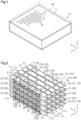
Fig. 1 is a perspective view showing a fiber-reinforced composite material according to an embodiment. -
Fig. 2 is a perspective view showing a fiber structure according to the embodiment. -
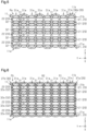
Fig. 3 is a top view of the fiber structure shown inFig. 2 . -
Fig. 4 is an end view taken along line 4-4 ofFig. 3 . -
Fig. 5 is an end view taken along line 5-5 ofFig. 3 . -
Fig. 6 is a cross-sectional view taken along line 6-6 ofFig. 3 . -
Fig. 7 is a top view showing a fiber-reinforced composite material according to a first modification. -
Fig. 8 is an explanatory top view showing a method for manufacturing a fiber structure according to a second modification. - A fiber structure and a fiber-reinforced composite material according to an embodiment will now be described with reference to
Figs. 1 to 6 . - As shown in
Fig. 1 , a fiber-reinforcedcomposite material 10 includes afiber structure 11 and a matrix resin Ma as a matrix material impregnated into thefiber structure 11. Thefiber structure 11 serves as a reinforcing substrate of the fiber-reinforcedcomposite material 10. The matrix resin Ma is, for example, a thermosetting resin. Examples of the thermosetting resin include an epoxy resin, a vinyl ester resin, an unsaturated polyester resin, and a phenol resin. For example, the fiber-reinforcedcomposite material 10 is formed by impregnating thefiber structure 11 with a thermosetting resin using a resin transfer molding (RTM) method. - As shown in
Fig. 2 , thefiber structure 11 includesmultiple fiber layers 20. Thefiber layers 20 are stacked in a stacking direction Z. Thefiber structure 11 does not change in configuration before and after thermal curing of the matrix material. - In the following description, the
fiber structure 11 is described as being placed horizontally. In the drawings, directions along a horizontal plane are indicated by an X-axis and a Y-axis, and a direction orthogonal to the horizontal plane is indicated by a Z-axis. The X-axis, the Y-axis, and the Z-axis are orthogonal to each other. A direction parallel to the X-axis is also referred to as a first direction X. A direction parallel to the Y-axis is also referred to as a second direction Y. The second direction Y is a direction orthogonal to the first direction X. The stacking direction Z is a direction parallel to the Z-axis. - The
fiber layers 20 include multiplefirst yarn layers 21 and one or more (multiple in this example)second yarn layers 22. Thefirst yarn layers 21 and thesecond yarn layers 22 are stacked in the stacking direction Z. Eachfirst yarn layer 21 includes multiplefirst yarns 31, and thefirst yarns 31 are arranged in the second direction Y. Thefirst yarns 31 each have a yarn main axis extending in the first direction X. Eachsecond yarn layer 22 includes multiplesecond yarns 32, and thesecond yarns 32 are arranged in the first direction X. Thesecond yarns 32 each have a yarn main axis extending in the second direction Y. - Each of the
first yarns 31 and thesecond yarns 32 is, for example, a fiber bundle in which multiple reinforcing continuous fibers are bundled. The reinforcing fibers may be organic fibers or inorganic fibers. Instead, the reinforcing fibers may be mixed fibers in which different types of organic fibers, different types of inorganic fibers, or organic fibers and inorganic fibers are mixed. Examples of the organic fibers include acrylic fibers, nylon fibers, polyester fibers, aramid fibers, poly-p-phenylenebenzobisoxazole fibers, and ultra-high-molecular weight polyethylene fibers. Examples of the inorganic fibers include carbon fibers, glass fibers, and ceramic fibers. Thefirst yarns 31 and thesecond yarns 32 of the present embodiment are made of carbon fibers. - One of the first yarn layers 21 is located at each of the opposite ends of the
fiber structure 11 in the stacking direction Z. Specifically, one of the multiple first yarn layers 21 is located at anend 11a, which is one end (lower end inFig. 2 ) of thefiber structure 11 in the stacking direction Z. Another of the first yarn layers 21 is located at anend 11b, which is the other end (upper end inFig. 2 ) of thefiber structure 11 in the stacking direction Z. Thefirst yarn layer 21 located at theend 11a of thefiber structure 11 is also referred to as a first end layer 21a. Thefirst yarn layer 21 located at theend 11b of thefiber structure 11 is also referred to as asecond end layer 21b. - Each
second yarn layer 22 is located between the corresponding first yarn layers 21 in the stacking direction Z. Each of the first end layer 21a and thesecond end layer 21b is adjacent to one of the second yarn layers 22 in the stacking direction Z. Two of the first yarn layers 21 are located between the corresponding second yarn layers 22 in the stacking direction Z. Onesecond yarn layer 22 and two first yarn layers 21 are alternately stacked in that order in the stacking direction Z between the first end layer 21a and thesecond end layer 21b. In this manner, the multiple first yarn layers 21 and the multiple second yarn layers 22 are stacked in the stacking direction Z, so that the multiple fiber layers 20 are stacked in the stacking direction Z. - The
first yarns 31 extend linearly in the first direction X. The first yarn layers 21 are stacked such that thefirst yarns 31 are arranged in the stacking direction Z. Thefirst yarns 31 arranged in the stacking direction Z are collectively referred to as afirst yarn group 31a. Multiplefirst yarn groups 31a are arranged in the second direction Y. - The
second yarns 32 do not interlace with thefirst yarns 31. In each of onefirst yarn layer 21 and the correspondingsecond yarn layer 22 adjacent to each other in the stacking direction Z, eachsecond yarn 32 in thesecond yarn layer 22 extends linearly in the second direction Y across thefirst yarns 31 in thefirst yarn layer 21. - The
fiber structure 11 includes a central region Ra and two end regions Rb. The central region Ra includes a center of thefiber structure 11 in the first direction X. Each of the end regions Rb is adjacent to the central region Ra in the first direction X. The two end regions Rb include ends 11c and 11d of thefiber structure 11 in the first direction X, respectively. - Each
second yarn layer 22 includes multiple endsecond yarns 32a. The endsecond yarns 32a are thesecond yarns 32 located at ends Rc of the central region Ra in the first direction X. Among the multiplesecond yarns 32 in eachsecond yarn layer 22, thesecond yarn 32 located at one end in the first direction X and thesecond yarn 32 located at the other end correspond to the endsecond yarns 32a. The endsecond yarns 32a are located at the opposite ends of the central region Ra in the first direction X. The central region Ra includes the endsecond yarns 32a located at the opposite ends in the first direction X, and multiplesecond yarns 32 located between the endsecond yarns 32a at one end in the first direction X and the endsecond yarns 32a at the other end. - The end regions Rb are regions of the
fiber structure 11 located outside the endsecond yarns 32a in the first direction X. In each of the multiple first yarn layers 21, the opposite ends of thefirst yarns 31 protrude beyond the endsecond yarns 32a toward the outside of thefiber structure 11. Each end region Rb thus includes the ends of thefirst yarns 31 protruding beyond the endsecond yarns 32a. The parts of thefirst yarns 31 other than the parts located in the end regions Rb are located in the central region Ra. - As shown in
Figs. 2 and3 , thefiber structure 11 includes multipleinterlayer binding yarns 35 that bind the multiple fiber layers 20 in the stacking direction Z. Each of theinterlayer binding yarns 35 is, for example, a fiber bundle in which multiple reinforcing continuous fibers are bundled. Theinterlayer binding yarns 35 are included in thefiber structure 11 by binding the multiple fiber layers 20 with theinterlayer binding yarns 35 in the weaving process used to produce thefiber structure 11. - The
interlayer binding yarns 35 are adjacent to thesecond yarns 32 in the first direction X. Theinterlayer binding yarns 35 each have a yarn main axis extending in the second direction Y. Theinterlayer binding yarns 35 engage with thefirst yarns 31 in the first end layer 21a and thefirst yarns 31 in thesecond end layer 21b. In other words, theinterlayer binding yarns 35 engage with thefirst yarns 31 of the first yarn layers 21 located at the opposite ends in the stacking direction Z of the multiple fiber layers 20. - Multiple
interlayer binding yarns 35 are located in each of the central region Ra and the two end regions Rb. Theinterlayer binding yarns 35 located in the central region Ra include multiple firstinterlayer binding yarns 36a and multiple secondinterlayer binding yarns 36b. The firstinterlayer binding yarns 36a and the secondinterlayer binding yarns 36b are disposed alternately in the first direction X. - As shown in
Figs. 4 and5 , each of the firstinterlayer binding yarns 36a and the secondinterlayer binding yarns 36b alternately engages with thefirst yarns 31 located in the first end layer 21a and thefirst yarns 31 located in thesecond end layer 21b, from one end to the other end in the second direction Y of thefiber structure 11. Thefirst yarns 31 with which the firstinterlayer binding yarns 36a are engaged in the first end layer 21a and thefirst yarns 31 with which the firstinterlayer binding yarns 36a are engaged in thesecond end layer 21b are located in thefirst yarn groups 31a adjacent to each other in the second direction Y. Similarly, thefirst yarns 31 with which the secondinterlayer binding yarns 36b are engaged in the first end layer 21a and thefirst yarns 31 with which the secondinterlayer binding yarns 36b are engaged in thesecond end layer 21b are located in thefirst yarn groups 31a adjacent to each other in the second direction Y. Each of the firstinterlayer binding yarns 36a and the secondinterlayer binding yarns 36b extends in the second direction Y, alternating the engagedfirst yarn 31 between thefirst yarn 31 in the first end layer 21a and thefirst yarn 31 in thesecond end layer 21b for eachfirst yarn group 31a. Each of the firstinterlayer binding yarns 36a and the secondinterlayer binding yarns 36b extends in the stacking direction Z between any two of thefirst yarn groups 31a adjacent to each other in the second direction Y. - The first
interlayer binding yarns 36a and the secondinterlayer binding yarns 36b pass through mutually different paths in a cross section of thefiber structure 11 orthogonal to the first direction X, so as to interlace with thefirst yarns 31. Each firstinterlayer binding yarn 36a alternately engages with thefirst yarn 31 located in the first end layer 21a and thefirst yarn 31 located in thesecond end layer 21b, from one end to the other end of thefiber structure 11 in the second direction Y. Each secondinterlayer binding yarn 36b alternately engages with thefirst yarn 31 located in thesecond end layer 21b and thefirst yarn 31 located in the first end layer 21a, from one end to the other end of thefiber structure 11 in the second direction Y. In afirst yarn group 31a in which the firstinterlayer binding yarn 36a engages with thefirst yarn 31 located in the first end layer 21a, the secondinterlayer binding yarn 36b engages with thefirst yarn 31 located in thesecond end layer 21b. In afirst yarn group 31a in which the firstinterlayer binding yarn 36a engages with thefirst yarn 31 located in thesecond end layer 21b, the secondinterlayer binding yarn 36b engages with thefirst yarn 31 located in the first end layer 21a. - As shown in
Fig. 3 , theinterlayer binding yarns 35 located in each end region Rb include a first endinterlayer binding yarn 37a and a second endinterlayer binding yarn 37b. The first endinterlayer binding yarn 37a and the second endinterlayer binding yarn 37b are adjacent to each other in the first direction X. One first endinterlayer binding yarn 37a is located in the end region Rb at each of theends fiber structure 11. One second endinterlayer binding yarn 37b is located in the end region Rb at each of theends fiber structure 11. - The first end
interlayer binding yarns 37a and the second endinterlayer binding yarns 37b are thinner than thesecond yarns 32. In other words, the multipleinterlayer binding yarns 35 located in each end region Rb are thinner than thesecond yarns 32. All theinterlayer binding yarns 35 provided in thefiber structure 11 may have the same thickness. In this case, the firstinterlayer binding yarns 36a and the secondinterlayer binding yarns 36b, which are the interlayerbinding yarns 35 located in the central region Ra, are also thinner than thesecond yarns 32. - The second end
interlayer binding yarns 37b are the interlayerbinding yarns 35 located at the endmost positions in the first direction X among theinterlayer binding yarns 35 provided in thefiber structure 11. In other words, theinterlayer binding yarns 35 located in the end regions Rb include theinterlayer binding yarns 35 located at the endmost positions in the first direction X among theinterlayer binding yarns 35 provided in thefiber structure 11. - As shown in
Fig. 6 , each of the first endinterlayer binding yarn 37a and the second endinterlayer binding yarn 37b alternately engages with thefirst yarn 31 located in the first end layer 21a and thefirst yarn 31 located in thesecond end layer 21b from one end to the other end of thefiber structure 11 in the second direction Y. Thefirst yarns 31 with which the first endinterlayer binding yarn 37a is engaged in the first end layer 21a and thefirst yarns 31 with which the first endinterlayer binding yarn 37a is engaged in thesecond end layer 21b are located in thefirst yarn groups 31a adjacent to each other in the second direction Y. Similarly, thefirst yarns 31 with which the second endinterlayer binding yarn 37b is engaged in the first end layer 21a and thefirst yarns 31 with which the second endinterlayer binding yarn 37b is engaged in thesecond end layer 21b are located in thefirst yarn groups 31a adjacent to each other in the second direction Y. Each of the first endinterlayer binding yarn 37a and the second endinterlayer binding yarn 37b extends in the second direction Y, alternating the engagedfirst yarn 31 between thefirst yarn 31 in the first end layer 21a and thefirst yarn 31 in thesecond end layer 21b for eachfirst yarn group 31a. Each of the first endinterlayer binding yarn 37a and the second endinterlayer binding yarn 37b extends in the stacking direction Z between any two of thefirst yarn groups 31a adjacent to each other in the second direction Y. - The first end
interlayer binding yarn 37a and the second endinterlayer binding yarn 37b pass through mutually different paths in a cross section of thefiber structure 11 orthogonal to the first direction X, so as to interlace with thefirst yarns 31. The first endinterlayer binding yarn 37a alternately engages with thefirst yarn 31 located in the first end layer 21a and thefirst yarn 31 located in thesecond end layer 21b, from one end to the other end of thefiber structure 11 in the second direction Y. The second endinterlayer binding yarn 37b alternately engages with thefirst yarn 31 located in thesecond end layer 21b and thefirst yarn 31 located in the first end layer 21a, from one end to the other end of thefiber structure 11 in the second direction Y. In afirst yarn group 31a in which the first endinterlayer binding yarn 37a engages with thefirst yarn 31 located in the first end layer 21a, the second endinterlayer binding yarn 37b engages with thefirst yarn 31 located in thesecond end layer 21b. In afirst yarn group 31a in which the first endinterlayer binding yarn 37a engages with thefirst yarn 31 located in thesecond end layer 21b, the second endinterlayer binding yarn 37b engages with thefirst yarn 31 located in the first end layer 21a. - In
Fig. 6 , a path through which each firstinterlayer binding yarn 36a passes is schematically shown as a first path R1 indicated by a long-dash double-short-dash line, and a path through which each secondinterlayer binding yarn 36b passes is schematically shown as a second path R2 indicated by a long-dash short-dash line. In a cross section of thefiber structure 11 orthogonal to the first direction X, the first endinterlayer binding yarn 37a passes through the first path R1, and the second endinterlayer binding yarn 37b passes through the second path R2. Therefore, the first endinterlayer binding yarn 37a, which is theinterlayer binding yarn 35 located in each end region Rb, passes through the same first path R1 as the firstinterlayer binding yarn 36a in the cross section of thefiber structure 11 orthogonal to the first direction X, so as to interlace with thefirst yarns 31. The second endinterlayer binding yarn 37b, which is the otherinterlayer binding yarn 35, passes through the same second path R2 as the secondinterlayer binding yarn 36b in the cross section of thefiber structure 11 orthogonal to the first direction X, so as to interlace with thefirst yarns 31. - As shown in
Fig. 3 , a pitch between the firstinterlayer binding yarn 36a and the secondinterlayer binding yarn 36b, which are adjacent to each other in the first direction X, is referred to as a first pitch L1. In the central region Ra, theinterlayer binding yarns 35 are separated from each other in the first direction X. - A pitch between the first end
interlayer binding yarn 37a and the second endinterlayer binding yarn 37b, which are adjacent to each other in the first direction X, is referred to as a second pitch L2. The first endinterlayer binding yarn 37a and the second endinterlayer binding yarn 37b, which are adjacent to each other in the first direction X, are in contact with each other in the first direction X. Therefore, the second pitch L2, which is the pitch in the first direction X between the interlayerbinding yarns 35 in each end region Rb, is smaller than the first pitch L1, which is the pitch in the first direction X between the interlayerbinding yarns 35 in the central region Ra. - Operation of the present embodiment will now be described.
- The first
interlayer binding yarns 36a and the secondinterlayer binding yarns 36b, which are located in the central region Ra, pass through mutually different paths in a cross section of thefiber structure 11 orthogonal to the first direction X, so as to interlace with thefirst yarns 31. Thus, the parts of thefirst yarns 31 located in the central region Ra are engaged with the firstinterlayer binding yarns 36a and the secondinterlayer binding yarns 36b from the opposite sides in the stacking direction Z. The engagement of theinterlayer binding yarns 35 in the central region Ra allows thesecond yarns 32 located in the central region Ra in the first direction X to be supported by being sandwiched from the opposite sides in the stacking direction Z by thefirst yarns 31 adjacent to thesecond yarns 32 in the stacking direction Z. Thus, the parts of the fiber layers 20 located in the central region Ra are bound together by the firstinterlayer binding yarns 36a and the secondinterlayer binding yarns 36b. - The first end
interlayer binding yarn 37a and the second endinterlayer binding yarn 37b located in each end region Rb interlace with thefirst yarns 31 through mutually different paths in a cross section of thefiber structure 11 orthogonal to the first direction X. Thus, parts of thefirst yarns 31 located in each end region Rb are engaged with the first endinterlayer binding yarn 37a and the second endinterlayer binding yarn 37b from the opposite sides in the stacking direction Z. The engagement of theinterlayer binding yarns 35 in each end region Rb allows the endsecond yarns 32a adjacent to the end region Rb in the first direction X to be supported to be sandwiched from the opposite sides in the stacking direction Z by thefirst yarns 31 adjacent to the endsecond yarns 32a in the stacking direction Z. Thus, the parts of the fiber layers 20 located in each end region Rb are bound together by the first endinterlayer binding yarn 37a and the second endinterlayer binding yarns 37b. - The second pitch L2, which is the pitch between the first end
interlayer binding yarn 37a and the second endinterlayer binding yarn 37b in each end region Rb, is smaller than the first pitch L1, which is the pitch between the firstinterlayer binding yarn 36a and the secondinterlayer binding yarn 36b in the central region Ra. Therefore, the fiber layers 20 are more firmly bound together by theinterlayer binding yarns 35 in each end region Rb than in the central region Ra. Such engagement of theinterlayer binding yarns 35 in each end region Rb allows the endsecond yarns 32a to be more strongly sandwiched from the opposite sides in the stacking direction Z by thefirst yarns 31 adjacent in the stacking direction Z than the othersecond yarns 32 located in the central region Ra. - The above-described embodiment has the following advantages.
- (1-1) The pitch in the first direction X between the interlayer
binding yarns 35 in each end region Rb is smaller than the pitch in the first direction X between the interlayerbinding yarns 35 in the central region Ra. Therefore, the fiber layers 20 are more firmly bound together by theinterlayer binding yarns 35 in each end region Rb than in the central region Ra. The endsecond yarns 32a, which are thesecond yarns 32 located at the ends Rc of the central region Ra in the first direction X, are less likely to fray from theends fiber structure 11 in the first direction X due to theinterlayer binding yarns 35 in the end regions Rb. Further, since such fraying is suppressed by binding the fiber layers 20 with theinterlayer binding yarns 35 in the weaving step, it is not necessary to add a step other than the weaving step in order to suppress fraying. Therefore, fraying from theends fiber structure 11 is suppressed while also preventing an increase in the manufacturing steps required for thefiber structure 11. - (1-2) Some of the
interlayer binding yarns 35 located in each end region Rb pass through the same first path R1 as the firstinterlayer binding yarns 36a in a cross section of thefiber structure 11 orthogonal to the first direction X, so as to interlace with thefirst yarns 31. The otherinterlayer binding yarns 35 pass through the same second path R2 as the secondinterlayer binding yarn 36b in the cross section of thefiber structure 11 orthogonal to the first direction X, so as to interlace with thefirst yarns 31. Therefore, theinterlayer binding yarns 35 located in the central region Ra and theinterlayer binding yarns 35 located in the end regions Rb share common paths in the cross section of thefiber structure 11 orthogonal to the first direction X. This facilitates the manufacture of thefiber structure 11. - (1-3) The
interlayer binding yarns 35 located in each end region Rb are thinner than thesecond yarns 32. Thus, as compared with a case in which theinterlayer binding yarns 35 located in each end region Rb are thicker than thesecond yarns 32, meandering of thefirst yarns 31 due to engagement of theinterlayer binding yarns 35 is less likely to occur. This limits a decrease in the strength of thefiber structure 11 caused by meandering of thefirst yarns 31. - (1-4) Fraying from the
ends fiber structure 11 in the first direction X can also be prevented by forming interlacing yarns at theends fiber structure 11. However, this approach requires additional tools specifically for forming the interlacing yarns. According to the above-described embodiment, theinterlayer binding yarns 35 located in the central region Ra and theinterlayer binding yarns 35 located in the end regions Rb share common paths in the cross section of thefiber structure 11 orthogonal to the first direction X. Consequently, there is no need to increase the number of tools for theinterlayer binding yarns 35 in the end regions Rb. This prevents fraying from theends fiber structure 11 while also minimizing the increase in the number of tools used in the weaving process. - The above-described embodiment may be modified as follows. The above-described embodiment and the following modifications can be combined as long as the combined modifications remain technically consistent with each other.
- As in a first modification shown in
Fig. 7 , theinterlayer binding yarns 35 located in each end region Rb may be melted by impregnating thefiber structure 11 with the matrix resin Ma as a thermosetting resin by using the RTM method. In this case, for example, a resin having a property of melting at the curing temperature of the matrix resin Ma can be used as the material of theinterlayer binding yarns 35 located in the end regions Rb. When an epoxy resin is used as the matrix resin Ma, for example, a phenoxy resin, a methyl methacrylate resin, or the like can be used as the material of theinterlayer binding yarns 35 located in the end regions Rb. When thefiber structure 11 is heated by the RTM method, the matrix resin Ma impregnated into thefiber structure 11 is thermally cured. At the same time, theinterlayer binding yarns 35 located in the end regions Rb disappear from thefiber structure 11. As a result, as shown inFig. 7 , afiber structure 11e in which theinterlayer binding yarns 35 are not present in the end regions Rb is obtained. In this modification, thefiber structure 11e serves as the reinforcing substrate of the fiber-reinforcedcomposite material 10. - The first modification has the following advantages.
- (2-1) The
interlayer binding yarns 35 located in the end regions Rb are melted by impregnating thefiber structure 11 with the thermosetting resin using the RTM method. Even if thefirst yarns 31 meander due to the engagement of theinterlayer binding yarns 35 in the end regions Rb, the meandering of thefirst yarns 31 is eliminated since theinterlayer binding yarns 35 located in the end regions Rb are melted by impregnating thefiber structure 11 with the thermosetting resin using the RTM method. This limits a decrease in the strength of thefiber structure 11 caused by meandering of thefirst yarns 31. - As in a second modification shown in
Fig. 8 ,fiber structures 11 may be manufactured by cutting a fiber body 11f, which is a precursor of thefiber structures 11. The fiber body 11f in this case has thefirst yarns 31, thesecond yarns 32, and theinterlayer binding yarns 35 similar to those of thefiber structure 11. In the fiber body 11f, central regions Ra and end regions Rb are arranged in the first direction X. Two end regions Rb are adjacent to each other in the first direction X between the central regions Ra in the first direction X. Thefirst yarns 31 of the end regions Rb adjacent to each other in the first direction X are continuous. Thefirst yarns 31 extend in the first direction X between the opposite ends of the fiber body 11f in the first direction X. After the fiber body 11f is manufactured, the fiber body 11f is cut along a cutting position C indicated by the long-dash short-dash line inFig. 8 . Accordingly, since the fiber body 11f is cut between the end regions Rb adjacent to each other in the first direction X, thefiber structures 11 are manufactured from the fiber body 11f. - In the
fiber structure 11, the number of the first yarn layers 21 located between the second yarn layers 22 in the stacking direction Z may be one or three or more. - The
second yarns 32 may be located in each end region Rb. In this case as well, fraying of the endsecond yarns 32a from theends fiber structure 11 in the first direction X is suppressed by theinterlayer binding yarns 35 in the end portion regions Rb. - In a cross section of the
fiber structure 11 orthogonal to the first direction X, the firstinterlayer binding yarns 36a may pass through a path different from the first path R1. In a cross section of thefiber structure 11 orthogonal to the first direction X, the secondinterlayer binding yarns 36b may pass through a path different from the second path R2. In summary, the paths of the firstinterlayer binding yarns 36a and the secondinterlayer binding yarns 36b may be changed as long as they pass through mutually different paths in a cross section of thefiber structure 11 orthogonal to the first direction X and interlace with thefirst yarns 31. - In a cross section of the
fiber structure 11 orthogonal to the first direction X, the first endinterlayer binding yarns 37a may pass through a path different from the first path R1. In a cross section of thefiber structure 11 orthogonal to the first direction X, the second endinterlayer binding yarns 37b may pass through a path different from the second path R2. In summary, theinterlayer binding yarns 35 located in the end regions Rb may pass through a path different from that of theinterlayer binding yarns 35 located in the central region Ra in a cross section of thefiber structure 11 orthogonal to the first direction X. - The number of the
interlayer binding yarns 35 located in each end region Rb may be three or more. For example, two or more first endinterlayer binding yarns 37a may be located in each end region Rb. Two or more second endinterlayer binding yarns 37b may be located in each end region Rb. - The
fiber structure 11 may be provided withinterlayer binding yarns 35 having different thicknesses. For example, the thickness of theinterlayer binding yarns 35 located in the central region Ra may be different from the thickness of theinterlayer binding yarns 35 located in the end regions Rb. - The thickness of the
interlayer binding yarns 35 located in the central region Ra may be greater than or equal to the thickness of thesecond yarns 32. - The thickness of the
interlayer binding yarns 35 located in the end regions Rb may be greater than or equal to the thickness of thesecond yarns 32. - In each end region Rb, the
interlayer binding yarns 35 may be separated from each other in the first direction X. In this case also, the second pitch L2, which is the pitch in the first direction X between the interlayerbinding yarns 35 in each end region Rb, is smaller than the first pitch L1, which is the pitch in the first direction X between the interlayerbinding yarns 35 in the central region Ra. - The
fiber structure 11 may be manufactured usingfirst yarns 31 andsecond yarns 32 impregnated with the matrix resin Ma. - At least one of the
first yarns 31, thesecond yarns 32, and theinterlayer binding yarns 35 may be fiber bundles formed by bundling multiple non-reinforcing fibers. The phrase "at least one of" as used in this description means "one or more" of desired options. As an example, the expression "at least one" as used in this description means "only one option" or "both two options" if the number of options is two. In another example, the phrase "at least one of" as used in this description means "only one single option" or "any combination of two or more options" if the number of options is three or more.
Claims (5)
- A fiber structure, comprising:multiple fiber layers stacked in a stacking direction; andmultiple interlayer binding yarns binding the multiple fiber layers in the stacking direction, whereinthe fiber layers include multiple first yarn layers and one or more second yarn layers located between the first yarn layers in the stacking direction,each of the first yarn layers includes multiple first yarns each having a yarn main axis extending in a first direction, the first yarns being arranged in a second direction orthogonal to the first direction,one of the first yarn layers is located at each of opposite ends of the fiber structure in the stacking direction,each of the second yarn layers includes multiple second yarns each having a yarn main axis extending in the second direction, the second yarns being arranged in the first direction without interlacing with the first yarns,each of the interlayer binding yarns is adjacent to one of the second yarns in the first direction, has a yarn main axis extending in the second direction, and is engaged with the first yarns of the first yarn layers located at the opposite ends of the fiber structure in the stacking direction,the fiber structure further comprises:a central region including a center of the fiber structure in the first direction; andtwo end regions respectively including opposite ends of the fiber structure in the first direction, each of the end regions being adjacent to the central region in the first direction,the second yarns include multiple end second yarns located at an end of the central region in the first direction,each of the second yarn layers includes the end second yarns,each of the central region and the two end regions includes the interlayer binding yarns,the interlayer binding yarns located in each of the end regions include:the interlayer binding yarn located at an endmost position in the first direction among the interlayer binding yarns included in the fiber structure, andtwo of the interlayer binding yarns that pass through mutually different paths in a cross section of the fiber structure orthogonal to the first direction, so as to interlace with the first yarns, anda pitch in the first direction between the interlayer binding yarns in the end regions is smaller than a pitch in the first direction between the interlayer binding yarns in the central region.
- The fiber structure according to claim 1, whereinthe interlayer binding yarns located in the central region include a first interlayer binding yarn and a second interlayer binding yarn,the first interlayer binding yarn and the second interlayer binding yarn pass through mutually different paths in a cross section of the fiber structure orthogonal to the first direction, so as to interlace with the first yarns, andamong the interlayer binding yarns located in the end regions,one or more of the interlayer binding yarns pass through the same path as the first interlayer binding yarn in a cross section of the fiber structure orthogonal to the first direction, so as to interlace with the first yarns, andother interlayer binding yarns pass through the same path as the second interlayer binding yarn in a cross section of the fiber structure orthogonal to the first direction, so as to interlace with the first yarns.
- The fiber structure according to claim 1 or 2, wherein the interlayer binding yarns located in the end regions are thinner than the second yarns.
- The fiber structure according to claim 1 or 2, wherein the interlayer binding yarns located in the end regions are melted by impregnating the fiber structure with a thermosetting resin using an RTM method.
- A fiber-reinforced composite material, comprising:the fiber structure according to claim 1 or 2; anda matrix material impregnated into the fiber structure.
Applications Claiming Priority (2)
| Application Number | Priority Date | Filing Date | Title |
|---|---|---|---|
| JP2022071036A JP7715075B2 (en) | 2022-04-22 | 2022-04-22 | Fiber structures and fiber-reinforced composites |
| PCT/JP2023/014409 WO2023204058A1 (en) | 2022-04-22 | 2023-04-07 | Fiber structure and fiber-reinforced composite material |
Publications (2)
| Publication Number | Publication Date |
|---|---|
| EP4512946A1 true EP4512946A1 (en) | 2025-02-26 |
| EP4512946A4 EP4512946A4 (en) | 2025-08-13 |
Family
ID=88420039
Family Applications (1)
| Application Number | Title | Priority Date | Filing Date |
|---|---|---|---|
| EP23791707.5A Pending EP4512946A4 (en) | 2022-04-22 | 2023-04-07 | FIBER STRUCTURE AND FIBER REINFORCED COMPOSITE |
Country Status (5)
| Country | Link |
|---|---|
| US (1) | US20250257502A1 (en) |
| EP (1) | EP4512946A4 (en) |
| JP (1) | JP7715075B2 (en) |
| CA (1) | CA3249262A1 (en) |
| WO (1) | WO2023204058A1 (en) |
Families Citing this family (1)
| Publication number | Priority date | Publication date | Assignee | Title |
|---|---|---|---|---|
| ES2994344T3 (en) * | 2020-07-03 | 2025-01-22 | Vestas Wind Sys As | Wind turbine blade |
Family Cites Families (6)
| Publication number | Priority date | Publication date | Assignee | Title |
|---|---|---|---|---|
| JP5461930B2 (en) | 2009-09-10 | 2014-04-02 | 三菱レイヨン株式会社 | Reinforcing fiber fabric and method for producing the same |
| JP2017106128A (en) | 2015-12-08 | 2017-06-15 | 株式会社Ihi | Three-dimensional reinforcing fiber woven fabric |
| JP2018066086A (en) * | 2016-10-20 | 2018-04-26 | 株式会社豊田自動織機 | RTM molding fiber preform and fiber reinforced composite |
| JP6620771B2 (en) | 2017-02-08 | 2019-12-18 | 株式会社豊田自動織機 | Fiber structure and fiber reinforced composite |
| WO2019012983A1 (en) | 2017-07-13 | 2019-01-17 | 株式会社 豊田自動織機 | Fiber structure and fiber-reinforced composite material |
| JP2019094578A (en) | 2017-11-17 | 2019-06-20 | 株式会社豊田自動織機 | Fiber structure and fiber reinforced composite material |
-
2022
- 2022-04-22 JP JP2022071036A patent/JP7715075B2/en active Active
-
2023
- 2023-04-07 US US18/857,345 patent/US20250257502A1/en active Pending
- 2023-04-07 CA CA3249262A patent/CA3249262A1/en active Pending
- 2023-04-07 WO PCT/JP2023/014409 patent/WO2023204058A1/en not_active Ceased
- 2023-04-07 EP EP23791707.5A patent/EP4512946A4/en active Pending
Also Published As
| Publication number | Publication date |
|---|---|
| WO2023204058A1 (en) | 2023-10-26 |
| CA3249262A1 (en) | 2025-06-17 |
| JP7715075B2 (en) | 2025-07-30 |
| JP2023160586A (en) | 2023-11-02 |
| EP4512946A4 (en) | 2025-08-13 |
| US20250257502A1 (en) | 2025-08-14 |
Similar Documents
| Publication | Publication Date | Title |
|---|---|---|
| US20160101591A1 (en) | Composite article | |
| EP2889324A1 (en) | Three-dimensional fiber-reinforced composite and method for producing three-dimensional fiber-reinforced composite | |
| US20250257502A1 (en) | Fiber structure and fiber-reinforced composite material | |
| JP2022182789A (en) | Fiber structure, and fiber-reinforced composite material | |
| JP2011074207A (en) | Preform of fiber reinforced composite material and method for producing the same | |
| EP3712309A1 (en) | Fiber construct, fiber-reinforced composite material, and method for manufacturing these | |
| EP3190307B1 (en) | Energy-absorbing member | |
| KR20120009128A (en) | Fabric reinforcement for composite material and fiber reinforced composite material prepreg | |
| EP3225725A1 (en) | Fibrous structure and fiber-reinforced composite material | |
| EP4549640A1 (en) | Fiber structure for fiber-reinforced composite material | |
| JP7609009B2 (en) | Fiber structures and fiber-reinforced composites | |
| EP3581690A1 (en) | Fiber structure and fiber reinforced composite material | |
| JP2025173417A (en) | Fiber structures and fiber-reinforced composites | |
| JP2026000064A (en) | Fiber structures and fiber-reinforced composites | |
| JP7287162B2 (en) | Fiber structures and fiber reinforced composites | |
| JP7845244B2 (en) | Fiber structures and fiber-reinforced composites | |
| JP7256001B2 (en) | Manufacturing method of ceramic tubular body | |
| JP4069202B2 (en) | Method for producing three-dimensional fiber reinforced composite lugs | |
| JP2015098156A (en) | Three-dimensional fiber-reinforced composite material | |
| JP2022119368A (en) | Fiber structure and fiber-reinforced composite material | |
| WO2013191232A1 (en) | Reinforcing fiber composite material and method for producing reinforcing fiber composite material | |
| JP2022122656A (en) | Fiber structure, fiber-reinforced composite material, and fiber structure manufacturing method | |
| JPH0198800A (en) | Supporting member for cryogenic equipment |
Legal Events
| Date | Code | Title | Description |
|---|---|---|---|
| STAA | Information on the status of an ep patent application or granted ep patent |
Free format text: STATUS: THE INTERNATIONAL PUBLICATION HAS BEEN MADE |
|
| PUAI | Public reference made under article 153(3) epc to a published international application that has entered the european phase |
Free format text: ORIGINAL CODE: 0009012 |
|
| STAA | Information on the status of an ep patent application or granted ep patent |
Free format text: STATUS: REQUEST FOR EXAMINATION WAS MADE |
|
| 17P | Request for examination filed |
Effective date: 20241029 |
|
| AK | Designated contracting states |
Kind code of ref document: A1 Designated state(s): AL AT BE BG CH CY CZ DE DK EE ES FI FR GB GR HR HU IE IS IT LI LT LU LV MC ME MK MT NL NO PL PT RO RS SE SI SK SM TR |
|
| DAV | Request for validation of the european patent (deleted) | ||
| DAX | Request for extension of the european patent (deleted) | ||
| A4 | Supplementary search report drawn up and despatched |
Effective date: 20250710 |
|
| RIC1 | Information provided on ipc code assigned before grant |
Ipc: D03D 11/00 20060101AFI20250704BHEP Ipc: B29B 15/12 20060101ALI20250704BHEP Ipc: B29C 70/16 20060101ALI20250704BHEP Ipc: B29C 70/48 20060101ALI20250704BHEP Ipc: D03D 1/00 20060101ALI20250704BHEP Ipc: D03D 15/587 20210101ALI20250704BHEP Ipc: B29K 105/08 20060101ALI20250704BHEP Ipc: D03D 13/00 20060101ALI20250704BHEP Ipc: B29C 70/22 20060101ALI20250704BHEP Ipc: B29B 11/16 20060101ALI20250704BHEP |
|
| GRAP | Despatch of communication of intention to grant a patent |
Free format text: ORIGINAL CODE: EPIDOSNIGR1 |
|
| STAA | Information on the status of an ep patent application or granted ep patent |
Free format text: STATUS: GRANT OF PATENT IS INTENDED |
|
| RIC1 | Information provided on ipc code assigned before grant |
Ipc: D03D 11/00 20060101AFI20251209BHEP Ipc: B29B 15/12 20060101ALI20251209BHEP Ipc: B29C 70/16 20060101ALI20251209BHEP Ipc: B29C 70/48 20060101ALI20251209BHEP Ipc: D03D 1/00 20060101ALI20251209BHEP Ipc: D03D 15/587 20210101ALI20251209BHEP Ipc: B29K 105/08 20060101ALI20251209BHEP Ipc: D03D 13/00 20060101ALI20251209BHEP Ipc: B29C 70/22 20060101ALI20251209BHEP Ipc: B29B 11/16 20060101ALI20251209BHEP |
|
| INTG | Intention to grant announced |
Effective date: 20260113 |
|
| GRAS | Grant fee paid |
Free format text: ORIGINAL CODE: EPIDOSNIGR3 |
|
| GRAA | (expected) grant |
Free format text: ORIGINAL CODE: 0009210 |
|
| STAA | Information on the status of an ep patent application or granted ep patent |
Free format text: STATUS: THE PATENT HAS BEEN GRANTED |