EP4512937A2 - Metal plating retention on additively manufacture plastic parts for an aircraft - Google Patents
Metal plating retention on additively manufacture plastic parts for an aircraft Download PDFInfo
- Publication number
- EP4512937A2 EP4512937A2 EP24182403.6A EP24182403A EP4512937A2 EP 4512937 A2 EP4512937 A2 EP 4512937A2 EP 24182403 A EP24182403 A EP 24182403A EP 4512937 A2 EP4512937 A2 EP 4512937A2
- Authority
- EP
- European Patent Office
- Prior art keywords
- support surface
- intermediate location
- lower support
- forming
- aircraft part
- Prior art date
- Legal status (The legal status is an assumption and is not a legal conclusion. Google has not performed a legal analysis and makes no representation as to the accuracy of the status listed.)
- Pending
Links
Images


Classifications
-
- C—CHEMISTRY; METALLURGY
- C25—ELECTROLYTIC OR ELECTROPHORETIC PROCESSES; APPARATUS THEREFOR
- C25D—PROCESSES FOR THE ELECTROLYTIC OR ELECTROPHORETIC PRODUCTION OF COATINGS; ELECTROFORMING; APPARATUS THEREFOR
- C25D5/00—Electroplating characterised by the process; Pretreatment or after-treatment of workpieces
- C25D5/54—Electroplating of non-metallic surfaces
- C25D5/56—Electroplating of non-metallic surfaces of plastics
-
- B—PERFORMING OPERATIONS; TRANSPORTING
- B64—AIRCRAFT; AVIATION; COSMONAUTICS
- B64F—GROUND OR AIRCRAFT-CARRIER-DECK INSTALLATIONS SPECIALLY ADAPTED FOR USE IN CONNECTION WITH AIRCRAFT; DESIGNING, MANUFACTURING, ASSEMBLING, CLEANING, MAINTAINING OR REPAIRING AIRCRAFT, NOT OTHERWISE PROVIDED FOR; HANDLING, TRANSPORTING, TESTING OR INSPECTING AIRCRAFT COMPONENTS, NOT OTHERWISE PROVIDED FOR
- B64F5/00—Designing, manufacturing, assembling, cleaning, maintaining or repairing aircraft, not otherwise provided for; Handling, transporting, testing or inspecting aircraft components, not otherwise provided for
- B64F5/10—Manufacturing or assembling aircraft, e.g. jigs therefor
-
- B—PERFORMING OPERATIONS; TRANSPORTING
- B29—WORKING OF PLASTICS; WORKING OF SUBSTANCES IN A PLASTIC STATE IN GENERAL
- B29C—SHAPING OR JOINING OF PLASTICS; SHAPING OF MATERIAL IN A PLASTIC STATE, NOT OTHERWISE PROVIDED FOR; AFTER-TREATMENT OF THE SHAPED PRODUCTS, e.g. REPAIRING
- B29C64/00—Additive manufacturing, i.e. manufacturing of three-dimensional [3D] objects by additive deposition, additive agglomeration or additive layering, e.g. by 3D printing, stereolithography or selective laser sintering
- B29C64/10—Processes of additive manufacturing
- B29C64/106—Processes of additive manufacturing using only liquids or viscous materials, e.g. depositing a continuous bead of viscous material
- B29C64/118—Processes of additive manufacturing using only liquids or viscous materials, e.g. depositing a continuous bead of viscous material using filamentary material being melted, e.g. fused deposition modelling [FDM]
-
- B—PERFORMING OPERATIONS; TRANSPORTING
- B33—ADDITIVE MANUFACTURING TECHNOLOGY
- B33Y—ADDITIVE MANUFACTURING, i.e. MANUFACTURING OF THREE-DIMENSIONAL [3D] OBJECTS BY ADDITIVE DEPOSITION, ADDITIVE AGGLOMERATION OR ADDITIVE LAYERING, e.g. BY 3D PRINTING, STEREOLITHOGRAPHY OR SELECTIVE LASER SINTERING
- B33Y40/00—Auxiliary operations or equipment, e.g. for material handling
- B33Y40/20—Post-treatment, e.g. curing, coating or polishing
-
- B—PERFORMING OPERATIONS; TRANSPORTING
- B33—ADDITIVE MANUFACTURING TECHNOLOGY
- B33Y—ADDITIVE MANUFACTURING, i.e. MANUFACTURING OF THREE-DIMENSIONAL [3D] OBJECTS BY ADDITIVE DEPOSITION, ADDITIVE AGGLOMERATION OR ADDITIVE LAYERING, e.g. BY 3D PRINTING, STEREOLITHOGRAPHY OR SELECTIVE LASER SINTERING
- B33Y70/00—Materials specially adapted for additive manufacturing
-
- C—CHEMISTRY; METALLURGY
- C25—ELECTROLYTIC OR ELECTROPHORETIC PROCESSES; APPARATUS THEREFOR
- C25D—PROCESSES FOR THE ELECTROLYTIC OR ELECTROPHORETIC PRODUCTION OF COATINGS; ELECTROFORMING; APPARATUS THEREFOR
- C25D9/00—Electrolytic coating other than with metals
- C25D9/04—Electrolytic coating other than with metals with inorganic materials
-
- B—PERFORMING OPERATIONS; TRANSPORTING
- B33—ADDITIVE MANUFACTURING TECHNOLOGY
- B33Y—ADDITIVE MANUFACTURING, i.e. MANUFACTURING OF THREE-DIMENSIONAL [3D] OBJECTS BY ADDITIVE DEPOSITION, ADDITIVE AGGLOMERATION OR ADDITIVE LAYERING, e.g. BY 3D PRINTING, STEREOLITHOGRAPHY OR SELECTIVE LASER SINTERING
- B33Y10/00—Processes of additive manufacturing
-
- B—PERFORMING OPERATIONS; TRANSPORTING
- B33—ADDITIVE MANUFACTURING TECHNOLOGY
- B33Y—ADDITIVE MANUFACTURING, i.e. MANUFACTURING OF THREE-DIMENSIONAL [3D] OBJECTS BY ADDITIVE DEPOSITION, ADDITIVE AGGLOMERATION OR ADDITIVE LAYERING, e.g. BY 3D PRINTING, STEREOLITHOGRAPHY OR SELECTIVE LASER SINTERING
- B33Y80/00—Products made by additive manufacturing
Definitions
- the embodiments are directed to parts for an aircraft and specifically to metal plating retention on additively manufacture plastic parts for an aircraft.
- Aircraft parts using exotic materials may be expensive and heavy. Aircraft parts may be additively manufactured from plastic and coated with strengthening materials. However due to different coefficients of expansion, the different materials may separate or fail.
- a method of additively manufacturing an aircraft part including: forming a base, defining a shape of the aircraft part, out of first thermoplastic polymer; forming a lower support surface onto discrete locations of the base by printing a mixture of a second thermoplastic polymer and a catalyst compound formed with metal onto the discrete locations, such that the lower support surface is formed with cavities; and forming an upper support surface by depositing, via electrolysis deposition, a metal plating onto the lower support surface along the discrete locations, to thereby form the aircraft part.
- forming the base includes printing, layer by layer, the base so that it extends from a bottom to a first intermediate location; forming the lower support surface includes printing, layer by layer, the lower support surface, from the first intermediate location to a second intermediate location, so that the lower support surface defines the cavities that extend from the second intermediate location toward the first intermediate location; and forming the upper support surface includes filling the cavities with the metal plating to anchor the metal plating to the lower support surface.
- cavities define a neck portion extending from the second intermediate location toward the first intermediate location, and a base portion that is larger than the neck portion.
- the neck portion is cylindrical having a first long axis extending from the second intermediate location toward the first intermediate location, and the base portion is oval having a second long axis that extends perpendicularly to the first long axis.
- first and second thermoplastic polymers are the same as each other.
- the first thermoplastic polymer is Acrylonitrile butadiene styrene (ABS).
- a motor cooling inlet 64 is defined at an aft motor housing 66. Surrounding the thrust shaft 56 are thrust bearings 68. A thrust plate 70 is located at the aft end of the ACM 10. The aft end of the ACM 10 also defines a bearing cooling inlet 72 and includes lead wires and a cover plate 74. Between the motor cooling inlet 64 and outlet 62 is a motor stator 76 and rotor 78.
Landscapes
- Engineering & Computer Science (AREA)
- Chemical & Material Sciences (AREA)
- Materials Engineering (AREA)
- Manufacturing & Machinery (AREA)
- Chemical Kinetics & Catalysis (AREA)
- Electrochemistry (AREA)
- Metallurgy (AREA)
- Organic Chemistry (AREA)
- Physics & Mathematics (AREA)
- Mechanical Engineering (AREA)
- Optics & Photonics (AREA)
- Inorganic Chemistry (AREA)
- Transportation (AREA)
- Aviation & Aerospace Engineering (AREA)
- Casting Or Compression Moulding Of Plastics Or The Like (AREA)
Abstract
Description
- The embodiments are directed to parts for an aircraft and specifically to metal plating retention on additively manufacture plastic parts for an aircraft.
- Aircraft parts using exotic materials may be expensive and heavy. Aircraft parts may be additively manufactured from plastic and coated with strengthening materials. However due to different coefficients of expansion, the different materials may separate or fail.
- Disclosed is a method of additively manufacturing an aircraft part, including: forming a base, defining a shape of the aircraft part, out of first thermoplastic polymer; forming a lower support surface onto discrete locations of the base by printing a mixture of a second thermoplastic polymer and a catalyst compound formed with metal onto the discrete locations, such that the lower support surface is formed with cavities; and forming an upper support surface by depositing, via electrolysis deposition, a metal plating onto the lower support surface along the discrete locations, to thereby form the aircraft part.
- In addition to one or more aspects of the method, or as an alternative, forming the base includes printing, layer by layer, the base so that it extends from a bottom to a first intermediate location; forming the lower support surface includes printing, layer by layer, the lower support surface, from the first intermediate location to a second intermediate location, so that the lower support surface defines the cavities that extend from the second intermediate location toward the first intermediate location; and forming the upper support surface includes filling the cavities with the metal plating to anchor the metal plating to the lower support surface.
- In addition to one or more aspects of the method, or as an alternative, cavities define a neck portion extending from the second intermediate location toward the first intermediate location, and a base portion that is larger than the neck portion.
- In addition to one or more aspects of the method, or as an alternative, the neck portion is cylindrical having a first long axis extending from the second intermediate location toward the first intermediate location, and the base portion is oval having a second long axis that extends perpendicularly to the first long axis.
- In addition to one or more aspects of the method, or as an alternative, the first and second thermoplastic polymers are the same as each other.
- In addition to one or more aspects of the method, or as an alternative, the first thermoplastic polymer is Acrylonitrile butadiene styrene (ABS).
- In addition to one or more aspects of the method, or as an alternative, the catalyst is palladium(II) chloride (PdCl2).
- In addition to one or more aspects of the method, or as an alternative, the aircraft part is additively manufactured utilizing stereolithography (SLA).
- In addition to one or more aspects of the method, or as an alternative, the aircraft part is additively manufactured utilizing fused deposition modeling (FDM).
- An aircraft part made from a method having one or more of the above disclosed aspects is disclosed herein.
- An air cycle machine of an aircraft having an aircraft part made from a method having one or more of the above disclosed aspects is disclosed herein.
- The following descriptions should not be considered limiting in any way. With reference to the accompanying drawings, like elements are numbered alike:
-
FIG. 1 shows an air cycle machine of an aircraft having parts that may be manufactured according to an embodiment; -
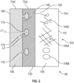
FIG. 2 shows a cross section of an aircraft part manufactured according to the embodiment; and -
FIG. 3 is a flowchart showing a process for manufacturing an aircraft part according to an embodiment. - A detailed description of one or more embodiments of the disclosed apparatus and method are presented herein by way of exemplification and not limitation with reference to the Figures.
-
FIG. 1 shows an air cycle machine (ACM) 10 of an aircraft 5 (shown schematically). The ACM 10 may include an outer case 11 that has aninlet housing 12 of acompressor inlet 14, and a motorcooling supply port 16. Downstream of theinlet housing 12 is aFOD screen 18. Atie rod 20 is surrounded by acompressor rotor 22. A diffusor rotor shroud (or shroud) 24 and an addheat housing 26 surround an addheat supply 28. The addheat housing 26 is connected to the outer case 11 via aforward frame member 25. Exterior to the addheat housing 26 is abackup ring 30 supporting a drive ring bearing 32. The drive ring bearing 32 is structurally coupled to a drive ring 34 and pinion 35. The ACM 10 includes a diffuser vane 36 and a variable diffusor actuator 40. Downstream of thecompressor rotor 22 is aninboard plate 42 structurally coupled to abacking plate 44. Anoutlet housing 46 defines acompressor outlet 48. Thecompressor outlet 48 is secured with abolt ring 50 to anintermediate frame member 52 of the ACM case 11. Arotor shaft 54 and aftthrust bearing shaft 56 are supported by journal bearings and asleeve 58. The journal bearing andsleeve 58 are supported by the case 11 via, e.g., theintermediate frame member 52 and anaft frame member 53. Thetie rod 20 is supported over therotor shaft 54 by atie rod support 60. The ACM case 11 defines a bearing andmotor cooling outlet 62. Amotor cooling inlet 64 is defined at anaft motor housing 66. Surrounding thethrust shaft 56 arethrust bearings 68. Athrust plate 70 is located at the aft end of the ACM 10. The aft end of the ACM 10 also defines a bearingcooling inlet 72 and includes lead wires and acover plate 74. Between themotor cooling inlet 64 andoutlet 62 is amotor stator 76 androtor 78. - Much of the ACM 10 may be additively manufactured with a 3D printer utilizing, e.g., stereolithography (SLA) or fused deposition modeling (FDM). Specifically, components of the ACM (or aircraft parts) may be additively manufactured utilizing a thermoplastic polymer and coating the thermoplastic with a metal plating. Metal-coated plastic aircraft parts may offer many advantages to a wide range of applications. The different materials, however, may have different coefficients of thermal expansions (CTEs), so that they could undergo dissimilar rates of deformation when subject to thermal stress. The embodiments herein provide a method of manufacturing such aircraft parts such that metal plating resists separation when expanding due to the different CTEs.
-
FIG. 2 shows anexample aircraft part 90 having abase 100 formed of a first thermoplastic polymer. Thebase 100 is built up so that it extends from a bottom 110 (or bottom face of the part) to a first intermediate location 120 (or first surface interface of the part) to define a first thickness TH1. Alower support surface 130 is deposited on top (e.g., over the first surface interface) of thebase 100 and is built up so that it extends to a second intermediate location 140 (or second surface interface) to define a second thickness TH2. Thebase 100 may includereinforcement structures 105. Thereinforcement structures 105 may be one or more of arigid lattice structure 105A (e.g. comprised of a material that is more rigid than a rest of the base 100),voids 105B orfiber 105C reinforcements, each is shown as a non-limiting example. The illustrated combination ofsuch reinforcements 105 is not intended on limiting the scope of the embodiments. - The
lower support surface 130 is formed of a mixture of a second thermoplastic polymer and a catalyst compound formed with metal. The thermoplastic polymers identified herein may be acrylonitrile butadiene styrene (ABS). The catalyst may be palladium(II) chloride (PdCl2). - An
upper support surface 150 is a metal plating formed via electrolysis deposition and is built up to define a third thickness TH3 so that it extends to a top 160 (or top face) of thepart 90. The lower andupper support surfaces aircraft part 90, such as locations that undergo thermal stress. To ensure the metal plating of theupper support surface 150 remains connected to the rest of theaircraft part 90, thelower support surface 130 may be formed to define an array of voids orcavities 170. When theupper support surface 150 is formed onto thelower support surface 130, the metal plating will form into thecavities 170 to increase bonding strength. - The
cavities 170 may define aneck portion 173 extending from the secondintermediate location 140 toward the firstintermediate location 120, and abase portion 175 that may be larger than theneck portion 173. Theneck portion 173 may be cylindrical having a first long axis L1 extending from the second intermediate 140 location toward the firstintermediate location 120. Thebase portion 175 may be oval having a second long axis L2 that extends perpendicularly to the first long axis L1. - Turning now to
FIG. 3 , a flowchart shows a method of additively manufacturing anaircraft part 90. As shown inblock 100, the method includes forming the base 100 out of the first thermoplastic polymer. As shown inblock 110A, forming thebase 100 includes printing, e.g., layer by layer, the base 100 so that it extends from a bottom 110 to the firstintermediate location 120. - As shown in
block 120, the method includes forming the lower support surface 113 onto discrete locations of thebase surface 110. This includes printing the mixture of the second thermoplastic polymer and the catalyst compound formed with metal onto the discrete locations. As indicated, the discrete locations are areas that experience relatively high thermal and operational stress. As shown inblock 120A, forming the lower support surface 113 includes printing, e.g., layer by layer, thelower support surface 130, from the firstintermediate location 120 to the secondintermediate location 140. This step includes defining in thelower support surface 130 thecavities 170 that extend from the secondintermediate location 140 toward the firstintermediate location 120. - As shown in
block 130, the method includes forming theupper support surface 150 by depositing, via electrolysis deposition, the metal plating onto thelower support surface 130 along the discrete locations of theaircraft part 90. As shown inblock 130A, forming theupper support surface 150 includes filling thecavities 170 with the metal plating to anchor the plating to thelower support surface 130. - The terminology used herein is for the purpose of describing particular embodiments only and is not intended to be limiting of the present disclosure. As used herein, the singular forms "a", "an" and "the" are intended to include the plural forms as well, unless the context clearly indicates otherwise. It will be further understood that the terms "comprises" and/or "comprising," when used in this specification, specify the presence of stated features, integers, steps, operations, elements, and/or components, but do not preclude the presence or addition of one or more other features, integers, steps, operations, element components, and/or groups thereof.
- Those of skill in the art will appreciate that various example embodiments are shown and described herein, each having certain features in the particular embodiments, but the present disclosure is not thus limited. Rather, the present disclosure can be modified to incorporate any number of variations, alterations, substitutions, combinations, sub-combinations, or equivalent arrangements not heretofore described, but which are commensurate with the scope of the present disclosure. Additionally, while various embodiments of the present disclosure have been described, it is to be understood that aspects of the present disclosure may include only some of the described embodiments. Accordingly, the present disclosure is not to be seen as limited by the foregoing description, but is only limited by the scope of the appended claims.
Claims (11)
- A method of additively manufacturing an aircraft part (90), comprising:forming a base (100), defining a shape of the aircraft part (90), out of first thermoplastic polymer;forming a lower support surface (130) onto discrete locations of the base (100) by printing a mixture of a second thermoplastic polymer and a catalyst compound formed with metal onto the discrete locations, such that the lower support surface (130) is formed with cavities (170); andforming an upper support surface (150) by depositing, via electrolysis deposition, a metal plating onto the lower support surface (130) along the discrete locations, to thereby form the aircraft part (90).
- The method of claim 1, wherein:forming the base (100) includes printing, layer by layer, the base (100) so that it extends from a bottom (110) to a first intermediate location (120);forming the lower support surface (130) includes printing, layer by layer, the lower support surface (130), from the first intermediate location (120) to a second intermediate location (140), so that the lower support surface (130) defines the cavities (170) that extend from the second intermediate location (140) toward the first intermediate location (120); andforming the upper support surface (150) includes filling the cavities (170) with the metal plating to anchor the metal plating to the lower support surface (130).
- The method of claim 2, wherein cavities (170) define a neck portion (173) extending from the second intermediate location (140) toward the first intermediate location (120), and a base portion (175) that is larger than the neck portion (173).
- The method of claim 3, wherein the neck portion (173) is cylindrical having a first long axis extending from the second intermediate location (140) toward the first intermediate location (120), and the base portion is oval having a second long axis that extends perpendicularly to the first long axis.
- The method of any preceding claim, wherein the first and second thermoplastic polymers are the same as each other.
- The method of any preceding claim, wherein the first thermoplastic polymer is Acrylonitrile butadiene styrene (ABS).
- The method of any preceding claim, wherein the catalyst is palladium(II) chloride (PdCl2).
- The method of any preceding claim, wherein the aircraft part (90) is additively manufactured utilizing stereolithography (SLA).
- The method of any preceding claim, wherein the aircraft part (90) is additively manufactured utilizing fused deposition modeling (FDM).
- An aircraft part (90) made from the method of claim 1.
- An air cycle machine (10) of an aircraft (5) comprising an aircraft part (90) made from the method of claim 1.
Applications Claiming Priority (1)
| Application Number | Priority Date | Filing Date | Title |
|---|---|---|---|
| US18/357,557 US20250033796A1 (en) | 2023-07-24 | 2023-07-24 | Metal plating retention on additively manufacture plastic parts for an aircraft |
Publications (2)
| Publication Number | Publication Date |
|---|---|
| EP4512937A2 true EP4512937A2 (en) | 2025-02-26 |
| EP4512937A3 EP4512937A3 (en) | 2025-07-02 |
Family
ID=91581052
Family Applications (1)
| Application Number | Title | Priority Date | Filing Date |
|---|---|---|---|
| EP24182403.6A Pending EP4512937A3 (en) | 2023-07-24 | 2024-06-14 | Metal plating retention on additively manufacture plastic parts for an aircraft |
Country Status (2)
| Country | Link |
|---|---|
| US (1) | US20250033796A1 (en) |
| EP (1) | EP4512937A3 (en) |
Families Citing this family (1)
| Publication number | Priority date | Publication date | Assignee | Title |
|---|---|---|---|---|
| US12384515B2 (en) | 2023-09-08 | 2025-08-12 | Hamilton Sundstrand Corporation | Airfoil formed of thermally adaptive materials and a thermoelectric junction |
Family Cites Families (9)
| Publication number | Priority date | Publication date | Assignee | Title |
|---|---|---|---|---|
| JP2007023361A (en) * | 2005-07-20 | 2007-02-01 | Mitsubishi Engineering Plastics Corp | Method for plating aromatic polycarbonate resin molded product and plated molded product |
| US8247050B2 (en) * | 2009-06-02 | 2012-08-21 | Integran Technologies, Inc. | Metal-coated polymer article of high durability and vacuum and/or pressure integrity |
| KR102440610B1 (en) * | 2017-12-29 | 2022-09-05 | 현대자동차 주식회사 | Composition of complex materail |
| US11453197B2 (en) * | 2018-07-03 | 2022-09-27 | Hamilton Sundstrand Corporation | Antimicrobial surfaces for flow path components |
| US11167482B2 (en) * | 2018-10-19 | 2021-11-09 | Hewlett-Packard Development Company, L.P. | Three-dimensional printing |
| US11643566B2 (en) * | 2019-09-09 | 2023-05-09 | Xerox Corporation | Particulate compositions comprising a metal precursor for additive manufacturing and methods associated therewith |
| US11131339B1 (en) * | 2020-03-04 | 2021-09-28 | The Boeing Company | High performance air journal bearing |
| US11802736B2 (en) * | 2020-07-29 | 2023-10-31 | Hamilton Sundstrand Corporation | Annular heat exchanger |
| US11692049B2 (en) * | 2020-09-18 | 2023-07-04 | Ford Global Technologies, Llc | Additively manufactured thermoset polymers for metal plating and metal plated parts formed therefrom |
-
2023
- 2023-07-24 US US18/357,557 patent/US20250033796A1/en active Pending
-
2024
- 2024-06-14 EP EP24182403.6A patent/EP4512937A3/en active Pending
Also Published As
| Publication number | Publication date |
|---|---|
| US20250033796A1 (en) | 2025-01-30 |
| EP4512937A3 (en) | 2025-07-02 |
Similar Documents
| Publication | Publication Date | Title |
|---|---|---|
| JP6058128B2 (en) | Aircraft engine auxiliary structures and processes related to auxiliary structures | |
| CN102556334B (en) | Foam stiffened structure and manufacture method thereof | |
| EP3019711B1 (en) | Plated polymer nosecone | |
| CN105829741B (en) | Bearing rings, inner rings, outer rings and bearings | |
| EP4148290B1 (en) | Turbomachinery shaft with variable lattice densities | |
| EP4411108B1 (en) | Metal plated additively manufactured plastic rotors and their method of manufacturing | |
| US20250033796A1 (en) | Metal plating retention on additively manufacture plastic parts for an aircraft | |
| US20110173812A1 (en) | Method for manufacturing the impeller of a centrifugal compressor | |
| US6796770B2 (en) | Impeller and method using solid free form fabrication | |
| US11668316B1 (en) | Rotor formed of multiple metals | |
| EP4411114B1 (en) | Metal plated additively manufactured plastic seal plates and their method of manufacturing | |
| US20160288207A1 (en) | Direct metal laser sintering machine | |
| EP4520529A1 (en) | Metal plated plastic acm part with internal thermally adaptive structure | |
| EP3615807B1 (en) | Technique to improve the performance of a pump with a trimmed impeller using additive manufacturing | |
| EP4497569B1 (en) | Metal plated additively manufactured plastic acm housings with internal thermally adaptive structure | |
| EP4497568A1 (en) | Method for forming a shaft for an air cycle machine | |
| EP4506150A1 (en) | Metal plated additively manufactured plastic acm rotors with internal thermally adaptive structure | |
| EP4497570A1 (en) | Metal plated additively manufactured plastic acm shrouds with internal thermally adaptive structure | |
| EP4497521A1 (en) | Metal plated additively manufactured plastic acm seal plates with internal thermally adaptive structure | |
| GB2621853A (en) | Rotor | |
| US20240255018A1 (en) | Metal plated additively manufactured plastic shafts and their method of manufacturing | |
| EP4411110A2 (en) | Metal plated additively manufactured plastic rotor shrouds and their method of manufacturing | |
| US20240318658A1 (en) | Lightweight Hydraulics Design for Improved 3D Printability | |
| Hermez et al. | Subtractive/Additive Rapid Prototyping of a Curve Spacer for Centrifugal Pump Impeller: Design, Manufacturing, and Simulation Analysis |
Legal Events
| Date | Code | Title | Description |
|---|---|---|---|
| PUAI | Public reference made under article 153(3) epc to a published international application that has entered the european phase |
Free format text: ORIGINAL CODE: 0009012 |
|
| STAA | Information on the status of an ep patent application or granted ep patent |
Free format text: STATUS: THE APPLICATION HAS BEEN PUBLISHED |
|
| AK | Designated contracting states |
Kind code of ref document: A2 Designated state(s): AL AT BE BG CH CY CZ DE DK EE ES FI FR GB GR HR HU IE IS IT LI LT LU LV MC ME MK MT NL NO PL PT RO RS SE SI SK SM TR |
|
| PUAL | Search report despatched |
Free format text: ORIGINAL CODE: 0009013 |
|
| AK | Designated contracting states |
Kind code of ref document: A3 Designated state(s): AL AT BE BG CH CY CZ DE DK EE ES FI FR GB GR HR HU IE IS IT LI LT LU LV MC ME MK MT NL NO PL PT RO RS SE SI SK SM TR |
|
| RIC1 | Information provided on ipc code assigned before grant |
Ipc: B33Y 70/00 20200101ALI20250526BHEP Ipc: B33Y 40/20 20200101ALI20250526BHEP Ipc: B33Y 80/00 20150101ALI20250526BHEP Ipc: B33Y 10/00 20150101ALI20250526BHEP Ipc: B29C 64/118 20170101ALI20250526BHEP Ipc: C25D 5/56 20060101AFI20250526BHEP |
|
| STAA | Information on the status of an ep patent application or granted ep patent |
Free format text: STATUS: REQUEST FOR EXAMINATION WAS MADE |
|
| 17P | Request for examination filed |
Effective date: 20251219 |