EP4512738A1 - Halbstarrer beutel zur aufbewahrung und ausgabe von nahrungsmitteln - Google Patents
Halbstarrer beutel zur aufbewahrung und ausgabe von nahrungsmitteln Download PDFInfo
- Publication number
- EP4512738A1 EP4512738A1 EP23198875.9A EP23198875A EP4512738A1 EP 4512738 A1 EP4512738 A1 EP 4512738A1 EP 23198875 A EP23198875 A EP 23198875A EP 4512738 A1 EP4512738 A1 EP 4512738A1
- Authority
- EP
- European Patent Office
- Prior art keywords
- semirigid
- upper edge
- pouch
- seal
- base
- Prior art date
- Legal status (The legal status is an assumption and is not a legal conclusion. Google has not performed a legal analysis and makes no representation as to the accuracy of the status listed.)
- Pending
Links
Images








Classifications
-
- B—PERFORMING OPERATIONS; TRANSPORTING
- B65—CONVEYING; PACKING; STORING; HANDLING THIN OR FILAMENTARY MATERIAL
- B65D—CONTAINERS FOR STORAGE OR TRANSPORT OF ARTICLES OR MATERIALS, e.g. BAGS, BARRELS, BOTTLES, BOXES, CANS, CARTONS, CRATES, DRUMS, JARS, TANKS, HOPPERS, FORWARDING CONTAINERS; ACCESSORIES, CLOSURES, OR FITTINGS THEREFOR; PACKAGING ELEMENTS; PACKAGES
- B65D75/00—Packages comprising articles or materials partially or wholly enclosed in strips, sheets, blanks, tubes or webs of flexible sheet material, e.g. in folded wrappers
- B65D75/008—Standing pouches, i.e. "Standbeutel"
-
- B—PERFORMING OPERATIONS; TRANSPORTING
- B65—CONVEYING; PACKING; STORING; HANDLING THIN OR FILAMENTARY MATERIAL
- B65D—CONTAINERS FOR STORAGE OR TRANSPORT OF ARTICLES OR MATERIALS, e.g. BAGS, BARRELS, BOTTLES, BOXES, CANS, CARTONS, CRATES, DRUMS, JARS, TANKS, HOPPERS, FORWARDING CONTAINERS; ACCESSORIES, CLOSURES, OR FITTINGS THEREFOR; PACKAGING ELEMENTS; PACKAGES
- B65D41/00—Caps, e.g. crown caps or crown seals, i.e. members having parts arranged for engagement with the external periphery of a neck or wall defining a pouring opening or discharge aperture; Protective cap-like covers for closure members, e.g. decorative covers of metal foil or paper
- B65D41/02—Caps or cap-like covers without lines of weakness, tearing strips, tags, or like opening or removal devices
-
- B—PERFORMING OPERATIONS; TRANSPORTING
- B65—CONVEYING; PACKING; STORING; HANDLING THIN OR FILAMENTARY MATERIAL
- B65D—CONTAINERS FOR STORAGE OR TRANSPORT OF ARTICLES OR MATERIALS, e.g. BAGS, BARRELS, BOTTLES, BOXES, CANS, CARTONS, CRATES, DRUMS, JARS, TANKS, HOPPERS, FORWARDING CONTAINERS; ACCESSORIES, CLOSURES, OR FITTINGS THEREFOR; PACKAGING ELEMENTS; PACKAGES
- B65D47/00—Closures with filling and discharging, or with discharging, devices
- B65D47/04—Closures with discharging devices other than pumps
- B65D47/06—Closures with discharging devices other than pumps with pouring spouts or tubes; with discharge nozzles or passages
- B65D47/12—Closures with discharging devices other than pumps with pouring spouts or tubes; with discharge nozzles or passages having removable closures
- B65D47/14—Closures with discharging devices other than pumps with pouring spouts or tubes; with discharge nozzles or passages having removable closures and closure-retaining means
-
- B—PERFORMING OPERATIONS; TRANSPORTING
- B65—CONVEYING; PACKING; STORING; HANDLING THIN OR FILAMENTARY MATERIAL
- B65D—CONTAINERS FOR STORAGE OR TRANSPORT OF ARTICLES OR MATERIALS, e.g. BAGS, BARRELS, BOTTLES, BOXES, CANS, CARTONS, CRATES, DRUMS, JARS, TANKS, HOPPERS, FORWARDING CONTAINERS; ACCESSORIES, CLOSURES, OR FITTINGS THEREFOR; PACKAGING ELEMENTS; PACKAGES
- B65D55/00—Accessories for container closures not otherwise provided for
- B65D55/16—Devices preventing loss of removable closure members
-
- B—PERFORMING OPERATIONS; TRANSPORTING
- B65—CONVEYING; PACKING; STORING; HANDLING THIN OR FILAMENTARY MATERIAL
- B65D—CONTAINERS FOR STORAGE OR TRANSPORT OF ARTICLES OR MATERIALS, e.g. BAGS, BARRELS, BOTTLES, BOXES, CANS, CARTONS, CRATES, DRUMS, JARS, TANKS, HOPPERS, FORWARDING CONTAINERS; ACCESSORIES, CLOSURES, OR FITTINGS THEREFOR; PACKAGING ELEMENTS; PACKAGES
- B65D75/00—Packages comprising articles or materials partially or wholly enclosed in strips, sheets, blanks, tubes or webs of flexible sheet material, e.g. in folded wrappers
- B65D75/52—Details
- B65D75/525—External rigid or semi-rigid supports
-
- B—PERFORMING OPERATIONS; TRANSPORTING
- B65—CONVEYING; PACKING; STORING; HANDLING THIN OR FILAMENTARY MATERIAL
- B65D—CONTAINERS FOR STORAGE OR TRANSPORT OF ARTICLES OR MATERIALS, e.g. BAGS, BARRELS, BOTTLES, BOXES, CANS, CARTONS, CRATES, DRUMS, JARS, TANKS, HOPPERS, FORWARDING CONTAINERS; ACCESSORIES, CLOSURES, OR FITTINGS THEREFOR; PACKAGING ELEMENTS; PACKAGES
- B65D75/00—Packages comprising articles or materials partially or wholly enclosed in strips, sheets, blanks, tubes or webs of flexible sheet material, e.g. in folded wrappers
- B65D75/52—Details
- B65D75/58—Opening or contents-removing devices added or incorporated during package manufacture
- B65D75/5805—Opening or contents-removing devices added or incorporated during package manufacture for tearing a side strip parallel and next to the edge, e.g. by means of a line of weakness
-
- B—PERFORMING OPERATIONS; TRANSPORTING
- B65—CONVEYING; PACKING; STORING; HANDLING THIN OR FILAMENTARY MATERIAL
- B65D—CONTAINERS FOR STORAGE OR TRANSPORT OF ARTICLES OR MATERIALS, e.g. BAGS, BARRELS, BOTTLES, BOXES, CANS, CARTONS, CRATES, DRUMS, JARS, TANKS, HOPPERS, FORWARDING CONTAINERS; ACCESSORIES, CLOSURES, OR FITTINGS THEREFOR; PACKAGING ELEMENTS; PACKAGES
- B65D75/00—Packages comprising articles or materials partially or wholly enclosed in strips, sheets, blanks, tubes or webs of flexible sheet material, e.g. in folded wrappers
- B65D75/52—Details
- B65D75/58—Opening or contents-removing devices added or incorporated during package manufacture
- B65D75/5855—Peelable seals
-
- B—PERFORMING OPERATIONS; TRANSPORTING
- B65—CONVEYING; PACKING; STORING; HANDLING THIN OR FILAMENTARY MATERIAL
- B65D—CONTAINERS FOR STORAGE OR TRANSPORT OF ARTICLES OR MATERIALS, e.g. BAGS, BARRELS, BOTTLES, BOXES, CANS, CARTONS, CRATES, DRUMS, JARS, TANKS, HOPPERS, FORWARDING CONTAINERS; ACCESSORIES, CLOSURES, OR FITTINGS THEREFOR; PACKAGING ELEMENTS; PACKAGES
- B65D75/00—Packages comprising articles or materials partially or wholly enclosed in strips, sheets, blanks, tubes or webs of flexible sheet material, e.g. in folded wrappers
- B65D75/52—Details
- B65D75/58—Opening or contents-removing devices added or incorporated during package manufacture
- B65D75/5861—Spouts
- B65D75/5872—Non-integral spouts
- B65D75/5883—Non-integral spouts connected to the package at the sealed junction of two package walls
-
- B—PERFORMING OPERATIONS; TRANSPORTING
- B65—CONVEYING; PACKING; STORING; HANDLING THIN OR FILAMENTARY MATERIAL
- B65D—CONTAINERS FOR STORAGE OR TRANSPORT OF ARTICLES OR MATERIALS, e.g. BAGS, BARRELS, BOTTLES, BOXES, CANS, CARTONS, CRATES, DRUMS, JARS, TANKS, HOPPERS, FORWARDING CONTAINERS; ACCESSORIES, CLOSURES, OR FITTINGS THEREFOR; PACKAGING ELEMENTS; PACKAGES
- B65D2207/00—Standing packages
-
- B—PERFORMING OPERATIONS; TRANSPORTING
- B65—CONVEYING; PACKING; STORING; HANDLING THIN OR FILAMENTARY MATERIAL
- B65D—CONTAINERS FOR STORAGE OR TRANSPORT OF ARTICLES OR MATERIALS, e.g. BAGS, BARRELS, BOTTLES, BOXES, CANS, CARTONS, CRATES, DRUMS, JARS, TANKS, HOPPERS, FORWARDING CONTAINERS; ACCESSORIES, CLOSURES, OR FITTINGS THEREFOR; PACKAGING ELEMENTS; PACKAGES
- B65D2575/00—Packages comprising articles or materials partially or wholly enclosed in strips, sheets, blanks, tubes or webs of flexible sheet material, e.g. in folded wrappers
- B65D2575/52—Details
- B65D2575/58—Opening or contents-removing devices added or incorporated during package manufacture
- B65D2575/583—Opening or contents-removing devices added or incorporated during package manufacture the non-integral spout having an elongate cross-sectional shape, e.g. canoe or boat shaped
Definitions
- the present disclosure is directed generally to semirigid pouches that are easy to sort and recycle. Such pouches are used primarily for storing and dispensing solid, liquid, or semi-liquid foodstuffs.
- the present disclosure provides novel semirigid pouch designs and methods of manufacturing semirigid pouches.
- the semirigid pouches while flexible, will substantially retain their three-dimensional shape and volume during and following product dispensing. As opposed to conventional pouches which lose their initial shape and become flat following product dispensing, the semirigid pouches do not rely on their stored contents to form their overall shape.
- the novel semirigid pouches are configured to substantially maintain their three-dimensional shape and volume even when empty. Maintaining their three-dimensional shape and volume allows the semirigid pouches to be easily sorted and recycled within existing rigid packaging recycling streams. Further, the semirigid pouches can be made of plastic or non-plastic materials.
- This semirigid pouch design is accomplished by sealing a lower edge of a wall of semirigid plastic or non-plastic materials to a rigid or semirigid base, enabling the pouch to stand up on the base. Portions of an upper edge of the wall are affixed together to form a space to hold the foodstuffs. Further, the present pouch design does not require an additional label to be applied by the manufacturer, as the present design provides a large, uninterrupted, surface area for printing of advertisements and/or labels directly to the outer surface of the pouch.
- the pouch includes a closure assembly to dispense the foodstuffs stored in the pouch.
- the closure assembly includes a spout affixed to portions of the upper edge or corner of the wall and a cap configured to engage with the spout.
- the semirigid wall is stiff enough such that the pouch may stand upright despite the additional weight of the spout and cap. Further, the cap may be tethered to the spout to conform with upcoming recycling regulations.
- the portions of the upper edge affixed together may form an upper seal, such as a tear open seal or a peelable seal. Breaking the tear open seal at least partially separates the portions of the upper edge and lower edge, thereby exposing the contents of the pouch.
- Seal tape may be used to prevent an upper portion to be torn from completely detaching from the semirigid wall, thereby conforming with certain recycling rules ensuring all parts of the pouch are recycled together.
- the peelable seal may be opened by peeling apart the affixed portions of the edge.
- a vertical seal is formed by affixing two vertical ends of the wall to each other.
- This vertical seal is preferably formed as a butt joint covered on either (or both) sides by seal tape.
- the butt joint provides a very smooth and continuous surface for printing or advertisements.
- Use of seal tape can also protect environmentally sensitive aspects of the wall.
- the base is semirigid and/or transparent rather than a conventional molded plastic base.
- the base is significantly lighter (and therefore less expensive) than the conventional base while still providing needed stiffness to the pouch.
- using a transparent base allows for the contents of the pouch to be visible to consumers who may wish to see the product prior to buying or dispensing.
- a semirigid pouch for storing and dispensing foodstuffs.
- the semirigid pouch includes a base.
- the base includes a base perimeter.
- the base perimeter includes a perimeter surface.
- the semirigid pouch further includes a semirigid wall.
- the semirigid wall includes an upper edge and a lower edge.
- the upper edge includes a first upper edge seal portion, a second upper edge seal portion, a first upper edge spout portion, and a second upper edge spout portion.
- the semirigid pouch further includes a closure system.
- the closure system includes a cap and a spout.
- the cap is configured to be removably engaged with the spout.
- the spout is affixed to the first upper edge spout portion and the second upper edge spout portion.
- the closure system may further include a tether.
- the tether is configured to mechanically couple the cap to the spout.
- the lower edge of the semirigid wall is affixed about the perimeter surface of the base.
- the first upper edge seal portion is affixed to the second upper edge seal portion, thereby forming a space to hold the foodstuffs.
- the semirigid wall further includes a first vertical end and a second vertical end.
- the first vertical end is affixed to the second vertical end.
- affixing the first vertical end to the second vertical end may form a butt joint.
- Seal tape may be applied over at least a portion of the butt joint formed by the first vertical end and the second vertical end.
- the upper edge may further include a first chamfer portion and a second chamfer portion.
- the first upper edge spout portion may be positioned within the first chamfer portion.
- the second upper edge spout portion may be positioned within the second chamfer portion.
- the semirigid wall further includes a first vertical end and a second vertical end.
- the first vertical end is affixed to the second vertical end.
- affixing the first vertical end to the second vertical end forms a butt joint.
- Seal tape may be applied over at least a portion of the butt joint formed by the first vertical end and the second vertical end.
- a method for manufacturing a semirigid pouch for storing and dispensing foodstuffs is provided.
- the semirigid pouch is configured to maintain a substantially consistent three-dimensional shape during and following dispensing of the foodstuffs.
- the method includes forming a base, wherein the base comprises a base perimeter, and wherein the base perimeter comprises a perimeter surface.
- the method may further include forming a semirigid wall, wherein the semirigid wall comprises an upper edge and a lower edge, and wherein the upper edge comprises a first upper edge seal portion and a second upper edge seal portion.
- the method may further include affixing the lower edge of the semirigid wall about the perimeter surface of the base.
- the method may further include forming a tear open seal by affixing the first upper edge seal portion to the second upper edge seal portion, thereby forming a space to hold the foodstuffs.
- FIG. 2 An example assembled pouch 10 is shown in FIG. 2 .
- the wall 100 is affixed to the base 200 via a lower seal 132.
- the upper portion of the wall 100 is affixed to itself via an upper seal 130.
- the closure assembly 300 is arranged in the middle of the upper seal 130.
- the upper seal 130 and lower seal 132 may be formed using one or more sealing techniques, such as heat sealing, conduction sealing, induction sealing, adhesive sealing, ultrasonic bonding, welding, laser sealing or any combination thereof. Further, the dimensions of the portions of the wall 100 and the base 200 used to form the upper and lower seals 130, 132 may be adjusted as needed.
- the example pouch 10 of FIG. 2 further includes a third seal 136 in the form of a butt joint 118 covered with seal tape 120.
- the butt joint 118 extends vertically along the wall 100 between the upper seal 130 and the lower seal 132.
- the butt joint 118 is covered at either or both the inner and outer surface 132, 134 by the seal tape 120 to reinforce the third seal 136.
- the outer surface 132 of the wall 100 may appear to be seamless to provide a large, uninterrupted, surface area for printing of advertisements and/or labels.
- the wall 100 is formed in the assembled state of FIG. 2 without a third seal 136. In these examples, the wall 100 may be created using thermoforming or similar manufacturing methods.
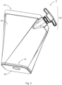
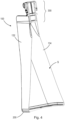
- FIG. 3 illustrates a variation of the pouch 10 of FIGS. 1 and 2 .
- an upper corner of the wall 100 along the upper seal 130 is chamfered.
- the closure assembly 300 is arranged within the chamfered corner. Arranging the closure assembly 300 within the chamfered corner may be advantageous for a variety of aesthetic and functional reasons, such as enhanced foodstuff dispensing positioning. The formation of the chamfer is described in greater detail with reference to FIG. 7 .
- FIGS. 5A-5C illustrate various views of the base 200 according to the present disclosure.
- FIG. 5A illustrates a top isometric view of the base 200
- FIG. 5B illustrates a bottom isometric view of the base 200
- FIG. 5C illustrates a bottom view of the base 200.
- the base 200 is intended to be a structure or plurality of structures capable of supporting and balancing the pouch 10 when not in use, i.e., when not dispensing foodstuffs or other materials.
- the base 200 when not in use, the base 200 is intended to support the weight and contents of the pouch 10 by acting as a standing surface on which the rest of the pouch 10 is supported such that no external support is needed, i.e., the pouch 10 can stand on its own.
- the base 200 is formed through one or more processes e.g., rotation molding, blow molding, injection molding, compression molding, extrusion molding, coining, cold forming and/or thermoforming.
- the base stock material can include a new sheet of stock material or unused portions of previously used stock material.
- the molding processes used utilize one or more heated dies.
- the paper stock material in the event the material or foodstuffs stored within the pouch 10 are liquid or semi-liquid, the paper stock material can be lacquered, coated, treated, or sprayed with a hydrophobic coating, e.g., wax or other plastics such as polyolefin dispersions, such that the paper pouch is waterproof.
- a hydrophobic coating e.g., wax or other plastics such as polyolefin dispersions
- the single sheet is cut to an initial shape and then formed into the defined shapes and structures set forth below. It should be appreciated that the single sheet of stock material is intended to be made primarily of one of the foregoing materials, but can include other trace materials, e.g., additives such as antioxidants, color pigment, slip agents, etc.
- the outer surface 206 and inner surface 208 have an imaginary major axis MAJ and an imaginary minor axis MIN (as shown in FIG. 5C ). It should be appreciated that these axes are referred to herein as "major axis MAJ" and "minor axis MIN.” In one example, as illustrated in FIG. 5C , example the length of major axis MAJ and the length of minor axis MIN are equal such that the outer surface 206 and the inner surface 208 substantially form a square shape. Although not shown, in another example the length of major axis MAJ is greater or longer than the length of minor axis MIN such that the outer surface 206 and the inner surface 208 substantially form a rectangular shape.
- outside corners of the outer surface 206 and the inner surface 208 can be filleted or rounded such that the outer surface 206 and the inner surface 208 substantially form a rectellipse (in the case that the major axis MAJ and minor axis MIN are different), or a squircle (in the case that the major axis MAJ and minor axis MIN are equal).
- the outer surface 206 can be substantially circular and can have a radius between 2 and 8 cm.
- the diameter of the circular base shape can be selected from between 2 cm to 30 cm.
- the length of the base 200 can be selected from between 2 cm and 30 cm.
- the base 200 Extending upward from the outer surface 206, i.e., extending in a second direction DR2, the base 200 includes an integrally formed base perimeter 202.
- the base perimeter 202 is formed as a lip or an extruded wall that extends in second direction DR2 and encompasses or surrounds inner surface 208 of the base 200.
- the base perimeter 202 includes an outer surface, i.e., a base perimeter surface 204 configured to receive, engage with, and seal to the inner surface 134 of wall 100 to form the upper seal 130.
- the base 200 may not be a rigid structure, but may instead be formed from a semirigid material.
- a semirigid base 200 is illustrated in FIG. 5D .
- a semirigid base 200 may be preferred to reduce material costs.
- the semirigid base 200 may also be more prone to lose its shape than the rigid base 200, which may prevent the container 10 as a whole from being recycled.
- the material and/or thickness of the semirigid base 200 may be chosen such that the semirigid base 200 is substantially transparent or translucent.
- the transparent base 200 may provide additional benefits in terms of allowing a consumer to view the product inside the pouch 10 prior to purchase.
- the semirigid base 200 of FIG. 5D will have a defined base perimeter 202 and a perimeter surface 204 to form a seal with the wall 100.
- the semirigid base 200 is typically a flat sheet of material rather than a thermoformed plastic body.
- the base perimeter 202 will not be formed as a lip or wall as shown in FIGS. 5A and 5B .
- the base perimeter 202 may be defined as the perimeter around a flat sheet of material, and the perimeter surface 204 may be defined as the thickness along the outer edge of the base 200. When forming the lower seal 132, this thickness is sealed to the inner surface 134 of the wall 100.
- the thickness of a semirigid base 200 will be significantly less than a rigid base 200.
- the thickness of the wall 100 may be less than or equal to the thickness of the semirigid base 200.
- the material of the semirigid base 200 may be of the same type as the material of the wall 100, though, in other examples, the wall 100 and the semirigid base 200 may be formed of different materials.
- the wall 100 can also contain an oxygen barrier layer comprising Ethylene-Vinyl-Alcohol or Poly-vinyl-Alcohol or a barrier coating such as metals, metal oxides or polymeric cellulose nano crystals.
- the wall 100 is made of renewable resources such as: paper and other cellulose-based materials; Polylactic acid; Polybutylene succinate; Thermoplastic Starch; Polyhydroxalkanoate; Polyhydroxybutyrate; and combinations thereof.
- wall 100 includes an upper edge 102, a lower edge 104, outer surface 132, an inner surface 134, a first vertical end 114, and a second vertical end 116.
- Inner surface 134 of the wall 100 is the surface configured to face inward, and substantially form the external barrier that defines internal space S, e.g., where inner surface 134 is configured to contact the stored foodstuffs within space S.
- the outer surface 132 is the surface diametrically opposed to inner surface 134, such that, when assembled and sealed (discussed below), the outer surface 132 faces the user or other outside elements external to the pouch 10.
- the outer surface 132 is configured to contact the inside of a user's hand when squeezing or dispensing foodstuffs from pouch 10. It should be appreciated that the wall 100 can take the shape of a substantially rectangular piece of material or may be formed with angular deviations from a rectangle.
- the upper edge 102 further includes a first upper edge spout portion 110 and a second upper edge spout portion 112. More specifically, the first upper edge spout portion 110 is arranged within the first upper edge seal portion 106, while the second upper edge spout portion 112 is arranged within the second upper edge seal portion 108.
- the upper edge spout portions 110, 112 are configured to seal to the spout 304 of the closure assembly 300 when the upper edge 102 of the wall 100 is folded together to form the upper seal 130.
- the upper edge spout portions 110, 112 are positioned such that the spout 304 will be horizontally centered in the pouch 10 when the upper seal 130 is formed, such as in the example of FIG. 2 .
- the spout 304 may be arranged in any practical position about the upper seal 130.
- Lower edge 104 is configured to be one continuous edge arranged to wrap around the entire perimeter surface 204 of the base 200 and seal to the perimeter surface 204, substantially forming the lower seal 132 along the surface area below the horizontal dashed line proximate to lower edge 104 in FIG. 6 .
- Lower seal 134 is established between this surface area and perimeter surface 204 of base 200 via one or more sealing techniques, e.g., heat sealing, conduction sealing, induction sealing, adhesive sealing, ultrasonic bonding, welding, laser sealing or any combination thereof.
- the lower edge 104 is intended to cover the entire width and length of each side face of the perimeter surface 204 such that, when sealed to the base 200, the lower edge 104 is substantially coincident with the lowest edge of the base perimeter 202, i.e., the lower edge 104 and the outer surface 206 of the base 200 simultaneously contact the planar surface on which pouch 10 is standing on. It should be appreciated that additional layers of material can be provided along upper edge 102 and/or along lower edge 104 to add additional stiffness as necessary.
- a third seal 136 is formed by sealing the first end 114 to the second end 116 of the wall 100 as a butt joint 118 (as shown in FIG. 2 ).
- These ends 114, 116 are "vertical" in that they are substantially orthogonal to the upper edge 102 and the lower edge 104 such that, when the pouch 10 is free-standing on the outer base surface 206, these portions will be disposed substantially vertically.
- these vertical sections do not need to be substantially orthogonal to the upper edge 102 and the lower edge 104, and can be disposed at other angles deviated from orthogonal, e.g., 5 degrees, 10 degrees, 15 degrees, etc.
- the butt joint 118 is formed by placing the first and second ends 114, 116 in contact with each other, i.e., abutting each other, and affixing, securing, or sealing one or more pieces of additional material over the ends 114, 116, sealing them together. By having at least one piece of additional material sealed over the two vertical ends of the wall 100, the space S can be completely sealed off. In some examples, two pieces of additional material can be used to seal the butt-joint 118, e.g., one piece on the inner surface 134 of ends 114, 116 and the other piece on the outer surface 132 of the ends 114, 116.
- the additional piece or additional pieces of material described herein can be a translucent, transparent, or opaque material, e.g., plastic, paper, or any of the other material types used to form the wall 100.
- seal tape 120 is applied longitudinally along the butt joint 118 between the upper seal 130 and the lower seal 132. Use of the seal tape 120 may be particularly important when the wall 100 is a paper-based material, such as plastic-coated paper. The cross-sectional edge of the coated paper may be uncoated, thereby exposing the paper to the contents of the pouch 10 potentially leading to wall 100 being damaged. Using seal tape 120 on the inner surface 134 of the wall 100 will protect the uncoated cross-sectional edges of the wall 100 from the contents of the container 10.
- FIG. 7 illustrates a variation of the unassembled wall 100 of FIG. 6 , and more specifically, a variation of the upper edge 102 forming the upper seal 130.
- the upper edge 102 of FIG. 7 includes a first upper edge seal portion 106 and a second upper edge seal portion 108 configured to form the upper seal 130 when the upper edge 102 is folded over onto itself.
- the first upper edge seal portion 106 includes the first upper edge spout portion 110
- the second upper edge seal portion 108 includes the second upper edge spout portion 112.
- FIG. 7 illustrates a variation of the unassembled wall 100 of FIG. 6 , and more specifically, a variation of the upper edge 102 forming the upper seal 130.
- the upper edge 102 of FIG. 7 includes a first upper edge seal portion 106 and a second upper edge seal portion 108 configured to form the upper seal 130 when the upper edge 102 is folded over onto itself.
- the first upper edge seal portion 106 includes the first upper edge spout portion 110
- the upper edge 102 further includes a first chamfer portion 122 and a second chamfer portion 124, such that the first chamfer portion 122 is arranged within the first upper edge seal portion 106, and the second chamfer portion 124 is arranged within the second upper edge seal portion 108.
- the chamfer portions 122, 124 correspond to chamfer cuts out of the corners of the wall 100.
- the first upper edge spout portion 110 is arranged within the first chamfer portion 122
- the second upper edge spout portion 112 is arranged within the second chamfer portion 124.
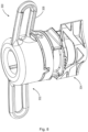
- FIGS. 8-10 illustrate various aspects of the closure system 300.
- closure system 300 includes a cap 302 and a spout 304.
- FIG. 8 illustrates an isometric elevational view of closure system 300 in an assembled state.
- FIG. 9 is an isometric view of the cap 302
- FIG. 10 is an isometric view of the spout 304.
- spout 304 includes a conduit 308 and a seal member 310.
- Conduit 308 is intended to be a tube, straw, or other longitudinal body with an inner volume configured to provide fluid communication of foodstuffs between pouch 10 and, for example, a user's mouth when engaged with conduit 308.
- the cap 302 is intended to rotatingly engage and disengage from spout 304, e.g., from conduit 308, and is arranged to cover, encompass, and seal at least the first aperture 312 of the conduit 308 such that foodstuffs stored within pouch 10 are prevented from exiting the aperture 312 when the cap 302 is engaged with the spout 304.
- the cap 302 includes a body portion 316, a lower ring 318, and at least one tether 306 coupling the body portion 316 to the lower ring 316.
- the body portion 316 is a substantially cylindrical body configured to encompass, cover, close, and seal the first aperture 112 of the conduit 106 when the cap 104 is engaged with the spout 304.
- the lower ring 318 is intended to be a ring-shaped annulus and is arranged to completely radially encompass at least a portion of the vertical height of spout 304.
- the lower ring 318 is intended to completely surround or encompass at least a portion of the conduit 308 and is arranged concentrically about the conduit 308.
- the lower ring 318 is configured to surround and rotatingly engage with a portion of conduit 308 such that the lower ring 318 stays rotatingly engaged with conduit 308 at all times after assembly.
- Tethering the body portion 316 of the cap 302 to the conduit 308 of the spout 304 (and therefore to the rest of the pouch 10) allows for compliance with recycling stream standards prohibiting separable materials in an attempt to ensure the entire pouch 10 (including all aspects of the wall 100, the base 200, and the closure system 300) is recycled.
- the at least one tether 306 can be made of the same materials as the body portion 316 and/or the lower ring 318 and that the body portion 316, the lower ring 318, and/or the tether 306 can be molded or otherwise formed in a single operation or as a single unitary part.
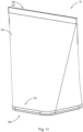
- FIGS. 11 and 12 illustrate a variation of the pouch 10 shown in FIG. 2 , more specifically, a pouch 10 configured with an upper seal 130 (rather than a closure system 300) in the form of a tear open seal 126 to enable a user to access the contents of the pouch 10.
- FIG. 11 illustrates a top isometric view of the pouch 10 having the tear away seal 126
- FIG. 12 illustrates a front view of the same pouch 10.
- the tear open seal 126 shown in FIGS. 11 and 12 replaces the upper seal 130 shown in FIG. 2 .
- the semirigid wall 100 may flex to create an opening along the upper edge 102 to enable a user to access the contents within the pouch 10.
- the pouch 10 of FIGS. 11 and 12 includes at least two seals; a lower seal 132 affixing the lower edge 104 of the wall 100 to the base 200, and the tear open seal 126 affixing the first upper edge seal portion 106 of the wall 100 to the second upper edge seal portion 108.
- the pouch 10 further includes a third seal 136 joining together two vertical ends 114, 116 of the unitary wall 100.
- the third seal 136 may be formed as a butt joint 118 overlayed with seal tape 120 on the inner surface 132 and/or the outer surface 134 of the wall 100.
- the tear open seal 126 is configured as an opening mechanism for the user to easily break the seal 126 to access the contents of the pouch 10.
- the tear open aspect of the seal 126 is manufactured by laser scoring a seal formed between two upper edge seal portions 106, 108 of the wall 100.
- a tear notch or tear tape may be incorporated in the tear open seal 126 to break the seal 126.
- the tear open seal 126 may include resealable features, such as a zipper.
- FIG. 13 illustrates a further variation of the pouch 10.
- the upper seal 130 is embodied as a peelable seal 144, rather than the tear open seal 126 shown in FIGS. 11 and 12 .
- the first and second upper edge seal portions 106, 108 of the wall 100 are sealed together using a resin or other adhesive material.
- a first tab 146 is affixed to the first upper edge seal portion 106 of the wall 100, while a second tab 148 is affixed to the second upper edge seal portion 108 of the wall 100.
- a user may easily peel open the peelable seal 144 by pulling the first tab 146 and the second tab 148 away from each other to separate the first and second upper edge seal portions 106, 108.
- tabs 146, 148 are illustrated in FIG. 13
- the tabs 146, 148 may be any size or shape required to facilitate the separation of the first and second upper edge seal portions 106, 108.
- the force required to peel apart the first and second upper edge seal portions 106, 108 may be configured according to the properties of the resin or other adhesive material.
- the resin or other adhesive material may be coextruded with the wall 100 during manufacturing. It should be understood that unlike the tear open seal 126 of FIGS. 11 and 12 , the peelable seal 144 does not require scoring, thereby simplifying the manufacturing process.
- FIG. 14 illustrates a flow chart of the steps of a method 800 for manufacturing the pouch 10 as shown, for example, in FIGS. 1 and 2 .
- the method 800 includes, in step 802, forming a base 200.
- the base 200 includes a base perimeter 202.
- the base perimeter 202 includes a perimeter surface 204.
- the method 800 further includes, in step 804, forming a semirigid wall 100.
- the semirigid wall 100 includes an upper edge 102 and a lower edge 104.
- the upper edge 102 includes a first upper edge seal portion 106, a second upper edge seal portion 108, a first upper edge spout portion 110, and a second upper edge spout portion 112.
- the method 800 further includes, in step 806, affixing a spout 304 of a closure system 300 to the first upper edge spout portion 110 and the second upper edge spout portion 112.
- the closure system 300 further includes a cap 302 configured to be removably engaged with the spout 304.
- the method 800 further includes, in step 808, affixing the lower edge 104 of the semirigid wall 100 about the perimeter surface of the base.
- the method 800 further includes, in step 810, affixing the first upper edge seal portion 106 to the second upper edge seal portion 108, thereby forming a space S to hold foodstuffs.
- the method 800 may further include, in optional step 812, affixing a first vertical end 114 of the semirigid wall 100 to a second vertical end 116 of the semirigid wall 100 to form a butt joint 118.
- the method 800 may further include, in optional step 814, applying seal tape 120 over at least a portion of the butt joint 118 formed by the first vertical end 114 of the semirigid wall 100 and the second vertical end 116 of the semirigid wall 100.
- FIG. 15 illustrates a flow chart of the steps of a method 900 for manufacturing the pouch 10 as shown, for example, FIGS. 11 and 12 .
- the method 900 includes, in step 902, forming a base 200.
- the base 200 includes a base perimeter 202.
- the base perimeter 202 includes a perimeter surface 204.
- the method 900 may further include, in step 906, affixing the lower edge 104 of the semirigid wall 100 about the perimeter surface of the base 200.
- the method 900 may further include, in step 908, forming a tear open seal 126 by affixing the first upper edge seal portion 106 to the second upper edge seal portion 108, thereby forming a space S to hold foodstuffs.
- the method 900 may further include, in optional step 910, affixing a first vertical end 114 of the semirigid wall 100 to a second vertical end 116 of the semirigid wall 100 to form a butt joint 118. Further to this example, the method 900 may further include, in optional step 912, applying seal tape 128 over at least a portion of the butt joint 118 formed by the first vertical end 114 of the semirigid wall 100 and the second vertical end 116 of the semirigid wall 100.
- the phrase "at least one,” in reference to a list of one or more elements, should be understood to mean at least one element selected from any one or more of the elements in the list of elements, but not necessarily including at least one of each and every element specifically listed within the list of elements and not excluding any combinations of elements in the list of elements.
- This definition also allows that elements may optionally be present other than the elements specifically identified within the list of elements to which the phrase "at least one" refers, whether related or unrelated to those elements specifically identified.
- inventive embodiments are presented by way of example only and that, within the scope of the appended claims and equivalents thereto, inventive embodiments may be practiced otherwise than as specifically described and claimed.
- inventive embodiments of the present disclosure are directed to each individual feature, system, article, material, kit, and/or method described herein.
Landscapes
- Engineering & Computer Science (AREA)
- Mechanical Engineering (AREA)
- Bag Frames (AREA)
Applications Claiming Priority (1)
| Application Number | Priority Date | Filing Date | Title |
|---|---|---|---|
| US18/455,513 US20250066091A1 (en) | 2023-08-24 | 2023-08-24 | Semirigid pouch for foodstuff storage and dispensing |
Publications (1)
| Publication Number | Publication Date |
|---|---|
| EP4512738A1 true EP4512738A1 (de) | 2025-02-26 |
Family
ID=88236706
Family Applications (1)
| Application Number | Title | Priority Date | Filing Date |
|---|---|---|---|
| EP23198875.9A Pending EP4512738A1 (de) | 2023-08-24 | 2023-09-21 | Halbstarrer beutel zur aufbewahrung und ausgabe von nahrungsmitteln |
Country Status (4)
| Country | Link |
|---|---|
| US (1) | US20250066091A1 (de) |
| EP (1) | EP4512738A1 (de) |
| AU (1) | AU2023237015A1 (de) |
| MX (1) | MX2023012637A (de) |
Families Citing this family (1)
| Publication number | Priority date | Publication date | Assignee | Title |
|---|---|---|---|---|
| US12495886B1 (en) * | 2025-07-02 | 2025-12-16 | Xavier Prax | Liquid reservoir system |
Citations (7)
| Publication number | Priority date | Publication date | Assignee | Title |
|---|---|---|---|---|
| KR20010079332A (ko) * | 2001-07-06 | 2001-08-22 | 이정민 | 원터치방식의 배출대 |
| US20030138169A1 (en) * | 2002-01-22 | 2003-07-24 | Mars Incorporated | Angled sealing pattern for retort pouch to create cold corners |
| EP1449787A1 (de) * | 2003-02-20 | 2004-08-25 | Curwood, Inc. | Verpackung aus Schrumpffolie und Verfahren zur Herstellung derselben |
| US20080063320A1 (en) * | 2004-05-27 | 2008-03-13 | Zaweigniederlassung Der Huhtamaki Deutschland | Tubular bag |
| US20090017239A1 (en) * | 2006-01-31 | 2009-01-15 | Felice Ursino | Hermetically Sealable, Easy-Opeanable, Flexible Container of Heat-Shrinklable Thermoplastic Material |
| WO2013037586A1 (de) * | 2011-09-14 | 2013-03-21 | Robert Bosch Gmbh | Standbodenbeutel und verfahren zur herstellung eines standbodenbeutels |
| US20220297900A1 (en) * | 2021-03-16 | 2022-09-22 | Winpak Ltd. | Closure system with barrier layer |
Family Cites Families (7)
| Publication number | Priority date | Publication date | Assignee | Title |
|---|---|---|---|---|
| US3799914A (en) * | 1970-04-29 | 1974-03-26 | Jenos Inc | Standable flexible container with straw |
| KR100969859B1 (ko) * | 2003-03-17 | 2010-07-13 | 가부시키가이샤 호소카와 요코 | 파스너 백 |
| JP5445747B2 (ja) * | 2009-06-25 | 2014-03-19 | 株式会社悠心 | フラットフィルム弁付き自立型液体包装袋 |
| CN202175279U (zh) * | 2011-07-21 | 2012-03-28 | 黄山永新股份有限公司 | 一种多片装护理垫包装袋 |
| WO2014096270A1 (en) * | 2012-12-20 | 2014-06-26 | Nestec S.A. | Flexible pouch wih a larger opening |
| US11305927B2 (en) * | 2014-04-04 | 2022-04-19 | Polytex Fibers Llc | Easy open plastic bags |
| WO2016020131A1 (en) * | 2014-08-07 | 2016-02-11 | Unilever N.V. | Packaging sachet |
-
2023
- 2023-08-24 US US18/455,513 patent/US20250066091A1/en active Pending
- 2023-09-21 EP EP23198875.9A patent/EP4512738A1/de active Pending
- 2023-09-25 AU AU2023237015A patent/AU2023237015A1/en active Pending
- 2023-10-25 MX MX2023012637A patent/MX2023012637A/es unknown
Patent Citations (7)
| Publication number | Priority date | Publication date | Assignee | Title |
|---|---|---|---|---|
| KR20010079332A (ko) * | 2001-07-06 | 2001-08-22 | 이정민 | 원터치방식의 배출대 |
| US20030138169A1 (en) * | 2002-01-22 | 2003-07-24 | Mars Incorporated | Angled sealing pattern for retort pouch to create cold corners |
| EP1449787A1 (de) * | 2003-02-20 | 2004-08-25 | Curwood, Inc. | Verpackung aus Schrumpffolie und Verfahren zur Herstellung derselben |
| US20080063320A1 (en) * | 2004-05-27 | 2008-03-13 | Zaweigniederlassung Der Huhtamaki Deutschland | Tubular bag |
| US20090017239A1 (en) * | 2006-01-31 | 2009-01-15 | Felice Ursino | Hermetically Sealable, Easy-Opeanable, Flexible Container of Heat-Shrinklable Thermoplastic Material |
| WO2013037586A1 (de) * | 2011-09-14 | 2013-03-21 | Robert Bosch Gmbh | Standbodenbeutel und verfahren zur herstellung eines standbodenbeutels |
| US20220297900A1 (en) * | 2021-03-16 | 2022-09-22 | Winpak Ltd. | Closure system with barrier layer |
Also Published As
| Publication number | Publication date |
|---|---|
| US20250066091A1 (en) | 2025-02-27 |
| AU2023237015A1 (en) | 2025-03-13 |
| MX2023012637A (es) | 2025-03-07 |
Similar Documents
| Publication | Publication Date | Title |
|---|---|---|
| US12071293B2 (en) | Containers for holding materials | |
| US9452857B2 (en) | Containers for holding materials | |
| CA2735866C (en) | Containers for holding materials | |
| US11613417B2 (en) | Container for foodstuff storage and dispensing | |
| EP1960286B1 (de) | Mit einem inneren beutel versehener behälter | |
| EP4512738A1 (de) | Halbstarrer beutel zur aufbewahrung und ausgabe von nahrungsmitteln | |
| US12263997B2 (en) | Closure system with barrier layer | |
| US20210094723A1 (en) | A package | |
| AU2012211504A1 (en) | Container being provided with an inner bag | |
| US20240359895A1 (en) | Containers for holding materials |
Legal Events
| Date | Code | Title | Description |
|---|---|---|---|
| PUAI | Public reference made under article 153(3) epc to a published international application that has entered the european phase |
Free format text: ORIGINAL CODE: 0009012 |
|
| STAA | Information on the status of an ep patent application or granted ep patent |
Free format text: STATUS: THE APPLICATION HAS BEEN PUBLISHED |
|
| AK | Designated contracting states |
Kind code of ref document: A1 Designated state(s): AL AT BE BG CH CY CZ DE DK EE ES FI FR GB GR HR HU IE IS IT LI LT LU LV MC ME MK MT NL NO PL PT RO RS SE SI SK SM TR |
|
| STAA | Information on the status of an ep patent application or granted ep patent |
Free format text: STATUS: REQUEST FOR EXAMINATION WAS MADE |
|
| 17P | Request for examination filed |
Effective date: 20250812 |