EP4512718A1 - Divan à porte de sortie d'urgence au-dessus de l'aile avec dossier rabattable pour sortie et dispositif de retenue gonflable pour protection des occupants - Google Patents
Divan à porte de sortie d'urgence au-dessus de l'aile avec dossier rabattable pour sortie et dispositif de retenue gonflable pour protection des occupants Download PDFInfo
- Publication number
- EP4512718A1 EP4512718A1 EP24195202.7A EP24195202A EP4512718A1 EP 4512718 A1 EP4512718 A1 EP 4512718A1 EP 24195202 A EP24195202 A EP 24195202A EP 4512718 A1 EP4512718 A1 EP 4512718A1
- Authority
- EP
- European Patent Office
- Prior art keywords
- subassembly
- seat pan
- backrest
- divan
- frame assembly
- Prior art date
- Legal status (The legal status is an assumption and is not a legal conclusion. Google has not performed a legal analysis and makes no representation as to the accuracy of the status listed.)
- Pending
Links
Images


Classifications
-
- B—PERFORMING OPERATIONS; TRANSPORTING
- B64—AIRCRAFT; AVIATION; COSMONAUTICS
- B64D—EQUIPMENT FOR FITTING IN OR TO AIRCRAFT; FLIGHT SUITS; PARACHUTES; ARRANGEMENT OR MOUNTING OF POWER PLANTS OR PROPULSION TRANSMISSIONS IN AIRCRAFT
- B64D11/00—Passenger or crew accommodation; Flight-deck installations not otherwise provided for
- B64D11/06—Arrangements of seats, or adaptations or details specially adapted for aircraft seats
- B64D11/0639—Arrangements of seats, or adaptations or details specially adapted for aircraft seats with features for adjustment or converting of seats
- B64D11/064—Adjustable inclination or position of seats
-
- B—PERFORMING OPERATIONS; TRANSPORTING
- B60—VEHICLES IN GENERAL
- B60N—SEATS SPECIALLY ADAPTED FOR VEHICLES; VEHICLE PASSENGER ACCOMMODATION NOT OTHERWISE PROVIDED FOR
- B60N2/00—Seats specially adapted for vehicles; Arrangement or mounting of seats in vehicles
- B60N2/02—Seats specially adapted for vehicles; Arrangement or mounting of seats in vehicles the seat or part thereof being movable, e.g. adjustable
- B60N2/20—Seats specially adapted for vehicles; Arrangement or mounting of seats in vehicles the seat or part thereof being movable, e.g. adjustable the back-rest being tiltable, e.g. to permit easy access
Definitions
- the present disclosure relates generally to a divan for use in an aircraft, and more particularly, to a divan including a repositionable upper frame assembly for achieving step-up height compliance to allow installation of the divan in front of an emergency exit, for instance a Type-III over-wing emergency exit door (OWEED).
- OBEED over-wing emergency exit door
- Type-I exits are defined as floor-level exits and are required to have a rectangular opening of not less than 24 inches wide by 48 inches high, with corner radii not greater than 8 inches.
- Type-II exits are required to have a rectangular opening of not less than 20 inches wide by 44 inches high, with corner radii not greater than 7 inches.
- Type-III exits to which the present disclosure finds particular application, are required to have a rectangular opening of not less than 20 inches wide by 36 inches high, with corner radii not greater than 7 inches.
- Type-IV exits are required to have a rectangular opening of not less than 19 inches wide by 26 inches high, with corner radii not greater than 6.3 inches.
- Type-II, Type-III, and Type-IV exits When located over a wing, at least Type-II, Type-III, and Type-IV exits have further requirements in terms of step-up height and step-down height, wherein step-up height means the distance from the cabin floor to the bottom of the required opening, and step-down height means the distance from the bottom of the required opening to a usable foothold.
- a Type-II exit when located over a wing, a Type-II exit must have a step-up height inside the aircraft of not more than 10 inches and a step-down height outside the aircraft of not more than 17 inches, a Type-III exit must have a step-up height inside the aircraft of not more than 20 inches and a step-down height outside the aircraft of not more than 27 inches, and Type-IV exits must have a step-up height inside the aircraft of not more than 29 inches and a step-down height outside the aircraft of not more than 36 inches.
- the requirements regarding the required opening size, corner radii, step-up height, and step-down height exist to facilitate passenger egress and rescue personnel ingress as necessary during an emergency event.
- passenger seating configurations may include individual passenger seats and divans (e.g., couches, sofas, etc.) in various number, locations, groupings, facing orientations, etc.
- Divans which typically include at least two laterally adjacent seating positions, are typically oriented side-facing and positioned against a fuselage wall considering their longitudinal length as compared to an individual passenger seat, as well as the clearance needed to transition the divan from an upright sitting position to a bed, commonly referred to as "berthing.”
- the present disclosure provides a divan including two or more laterally adjacent seats for positioning in relation to an emergency exit in an aircraft, for instance a Type-III over-wing exit pursuant to FAR Sec. 25.801.
- the divan includes a lower frame assembly attachable to a floor and an upper frame assembly including movable elements.
- the upper frame assembly includes a seat pan subassembly movably attached to the lower frame assembly, and a backrest subassembly rotatably attached to the seat pan subassembly.
- the lower frame assembly further includes a step positioned behind the seat pan subassembly, wherein the step and the backrest subassembly, when the backrest subassembly is in the second position, are substantially horizontally aligned.
- the present disclosure provides a passenger seating configuration for an aircraft including an emergency exit positioned in an exterior wall and over a wing of the aircraft.
- the passenger seating arrangement includes a divan, as provided above, positioned against the exterior wall and facing inboard, with the divan including two or more laterally adjacent seats, and at least one of the seats positioned directly in front of the emergency exit.
- embodiments of the inventive concepts disclosed herein are directed to a divan assembly for installation, for example, in an aircraft passenger cabin.
- divan means any passenger seat, couch, sofa, and the like.
- the divan includes repositionable elements that allow the divan to be converted between an upright sitting position for use during taxi, takeoff, and landing (TTOL) and during flight, and a collapsed configured for use during an emergency event.
- the divan is capable of being positioned directly in front of an emergency exit, for instance a Type-III over-wing emergency exit door (OWEED) because the divan, when collapsed, is capable of achieving a step-up height of not more than 20 inches.
- OBEED over-wing emergency exit door
- the divan may include one or more seats defining one or more seating positions. In the case of two or more seats, the seats are positioned laterally adjacent such that two or more passengers may be seated side-by-side when the divan is configured upright for seating.
- the divan includes at least two seats, wherein at least one of the seats is repositionable to achieve step-up compliance as discussed further below.
- the divan may include three seats wherein one end seat is configured to be repositionable and the other two seats may lack repositionable functionality to simplify cost and complexity of the divan.
- the divan may include at least two repositionable seats for installation flexibility.
- one or more of the ends seats and the middle seat may be configured as repositionable as provided herein.
- most of the figures show an individual seat that may be part of a larger divan assembly.
- the repositionability functionality of the divan is compatible for use with additional adjustment capabilities, for instance berthing frame assemblies.
- Some advantages of the divan according to the present disclosure include, but are not limited to, greater flexibility in terms of passenger seating in an aircraft passenger cabin, the ability to position the divan, and more particularly a repositionable seat of the divan, directly in front of a predefined type of emergency exit while complying with exit egress/ingress requirements, and a TTOL compliant divan capable of being installed against a fuselage wall and in a side-facing orientation.
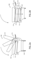
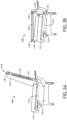
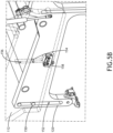
- FIGS. 1A-C illustrate a portion of a passenger cabin 100 of an aircraft, such as a business or private jet.
- an emergency exit 102 is positioned in a fuselage wall of the aircraft.
- the emergency exit 102 may be a Type-I, Type-II, or Type-III over-wing emergency exit door (OWEED) as classified according to Federal Aviation Regulation (FAR) Sec. 25.801.
- a divan 104 is installed in the passenger cabin 100 oriented side-facing (i.e., inboard facing) and positioned against the fuselage wall 106.
- the divan 104 includes three seats 108 defining three upright seating positions for accommodating three passengers. At least one of the seats 108, for example positioned at the end of the divan 104, is positioned directly in front of the emergency exit 102 and is reconfigurable for step-up compliance with the requirements of the emergency exit 102.
- FIG. 1B illustrates the backrest subassembly 110 in each of its fully upright, fully overlaid, and intermediate positions.
- FIG. 1C illustrates the backrest subassembly 110 rotated to overlay the seat pan subassembly 112, and the seat pan assembly 112 lowered toward the floor 114.
- FIG. 1A therefore illustrates the seat 108 upright for sitting and
- FIG. 1C illustrates the seat 108 repositioned for emergency egress/ingress step-up compliance. Comparing FIGS. 1A and 1C , it is evident that the seat pan assembly is repositioned vertically lower than the seat pans of the other seats.
- the backside of the backrest subassembly 110 functioning and the stepping surface is no higher than the maximum step-up height, for instance not more than 20 inches.
- the lower frame assembly 120 further includes a step 122 that extends away from the outboard side of the divan seat 108.
- the step 122 may include a support arm 124, or a pair support arms in a symmetrical arrangement, extending upwardly and supporting a platform 126 positioned atop the one or more support arms 124.
- the platform 126 may function as a stepping surface and/or a filler occupying the empty space between the backrest assembly 110 and the fuselage wall. As shown, the platform 126 and the repositioned backrest assembly 110 are substantially horizontally aligned to provide a substantially continuous stepping surface for egress and ingress.
- FIGS. 3A and 3B schematically illustrate a passenger restraint assembly 128 for use with the divan seat 108.
- the passenger restrain assembly 128 includes a first webbing portion 130 routed through the backrest subassembly 110, and a second webbing portion 132, continuous with the first webbing portion 130, routed through the seat pan subassembly 112.
- the second webbing portion 132 may be wound on a retractor 134 operable for paying in and out the webbing.
- an airbag 136 may be mounted to the first webbing portion 130.
- the first webbing portion 130 may be guided out of the top of the backrest subassembly 110 through an exit bezel 138 positioned at the top of the backrest subassembly 110.
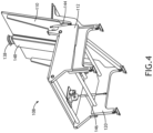
- FIG. 4 illustrates dampers for motion control of the repositionable components of the divan seat 108.
- at least one first damper 144 has a first end mounted to the backrest subassembly 110 and a second end mounted to the seat pan subassembly 112.
- the first damper 144 may be a gas spring, and two gas springs may be provided in a symmetrical arrangement on both sides of the divan seat 108. In use, each first damper 144 controls the rotational motion of the backrest subassembly 110.
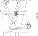
- FIGS. 5A and 5B illustrate an exemplary interface for guiding motion of the seat pan subassembly 112 relative to the lower frame assembly 120.
- the motion path of the seat pan subassembly 112 is vertical.
- guides 150 carried on the seat pan subassembly 112 travel within slots or guideways 152 formed on the lower frame assembly 120, for instance on each leg of the lower frame assembly 120.
- Each guideway 152 may be linear and oriented vertical or near vertical.
- the lower frame assembly 120 may carry guides 154 configured to travel along slots or guideways 156 formed on the seat pan subassembly 112. As the seat pan subassembly 112 moves up and down, the guides travel within their respective guideways.
- the guides and guideways may be provided in a symmetrical arrangement on both sides of the divan seat.
- FIGS. 5A and 5B further illustrate a locking functionality of the guide154 and guideway 156 pairing.
- a seat pan lock 158 carried on an inboard side of the seat pan subassembly 112 is configured to capture the guide 154 to lock the seat pan subassembly 112 in the fully raised position relative to the lower frame assembly 120.
- FIG. 5B when the seat pan lock 158 is open to release the captive guide 154, the seat pan subassembly 112 is able to move relative to the lower frame assembly 120.
- Seat pan locks 158 may be provided in a symmetrical arrangement on both sides of the divan seat.
- FIG. 6 illustrates a backrest lock 160 and pin 162 pairing.
- a backrest lock 160 mounted to the seat pan subassembly 112 is configured to capture a pin mounted to the backrest subassembly 110.
- the backrest lock 160 captures the pin 160 to prevent forward rotation of the backrest subassembly 110.
- the backrest lock 162 is open, the captive 162 is released thereby allowing the backrest subassembly 110 to rotate forward toward horizontal.
- Backrest locks 160 and pins 162 may be provided in a symmetrical arrangement on both sides of the divan seat.
- FIG. 6 further illustrates an exemplary rotation axis 164 of the backrest subassembly 110.
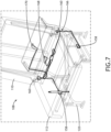
- FIG. 7 illustrates further elements and aspects of the lock assembly 166 for locking component motions of the divan seat 108.
- the divan seat 108 may be equipped with a plurality of seat pan locks 158 and backrest locks 160 for locking the respective motions of the backrest subassembly 110 and the seat pan subassembly 112.
- the lock assembly 166 further includes a first actuator 168 positioned on and accessible from an inboard side of the divan seat 108, and a second actuator 170 positioned on an accessible from an outboard side of the divan seat 108.
- Each actuator 168, 170 be a pull strap as shown.
- the lock assembly 166 further includes cabling routed through the divan seat 108 and interconnecting each of the first and second actuators 168, 170 to each of the locks 158, 160 of each of the backrest lock subassembly 110 and the seat pan lock subassembly 112.
- the cabling may be Bowden-style cable including a wire configured to translate within a cable jacket.
- the mechanism by which the locks open and close may be conventional.
- the locks 158, 160 may be disengaged by either of the actuators 168 or 170.
- FIGS. 8A and 8B further illustrate the inboard and outboard pull strap 168, 170 locations for releasing the seat components for repositioning.
- the inboard pull strap 168 is shown presented at the front of the seat at the interface between the seat pan subassembly 112 and the backrest subassembly 110, for use from within the aircraft.
- the outboard pull strap 170 is shown presented at the back of the seat at the interface between the backrest subassembly 110 and the platform 126, for use from outside of the aircraft.
Landscapes
- Engineering & Computer Science (AREA)
- Aviation & Aerospace Engineering (AREA)
- Transportation (AREA)
- Mechanical Engineering (AREA)
- Seats For Vehicles (AREA)
Applications Claiming Priority (2)
| Application Number | Priority Date | Filing Date | Title |
|---|---|---|---|
| IN202341056760 | 2023-08-24 | ||
| US18/377,163 US12497174B2 (en) | 2023-08-24 | 2023-10-05 | OWEED divan with fold-down backrest for egress and inflatable restraint for occupant protection |
Publications (1)
| Publication Number | Publication Date |
|---|---|
| EP4512718A1 true EP4512718A1 (fr) | 2025-02-26 |
Family
ID=92459152
Family Applications (1)
| Application Number | Title | Priority Date | Filing Date |
|---|---|---|---|
| EP24195202.7A Pending EP4512718A1 (fr) | 2023-08-24 | 2024-08-19 | Divan à porte de sortie d'urgence au-dessus de l'aile avec dossier rabattable pour sortie et dispositif de retenue gonflable pour protection des occupants |
Country Status (1)
| Country | Link |
|---|---|
| EP (1) | EP4512718A1 (fr) |
Citations (8)
| Publication number | Priority date | Publication date | Assignee | Title |
|---|---|---|---|---|
| US4679749A (en) * | 1984-09-28 | 1987-07-14 | Falcon Jet Corporation | Auxiliary airplane seats |
| EP1968814B1 (fr) * | 2006-01-05 | 2009-11-11 | Intier Automotive Inc. | Ensemble siege se pliant a plat |
| WO2012162123A1 (fr) * | 2011-05-20 | 2012-11-29 | Johnson Controls Technology Company | Stade et siège rabattable |
| US20170305306A1 (en) * | 2016-04-21 | 2017-10-26 | Hyundai Motor Company | Auxiliary seat storage structure |
| US20190217754A1 (en) * | 2018-01-18 | 2019-07-18 | Toyota Jidosha Kabushiki Kaisha | Vehicle seat |
| EP3222523B1 (fr) * | 2016-03-23 | 2019-09-11 | Airbus Operations GmbH | Banquette de siège pliable |
| EP2939920B1 (fr) * | 2014-04-29 | 2021-10-13 | Airbus Operations GmbH | Agencement de panneau de plancher déployable pour zone de cabine d'aéronef |
| US20230234482A1 (en) * | 2022-01-24 | 2023-07-27 | Faurecia Automotive Seating, Llc | Vehicle and occupant support for a vehicle |
-
2024
- 2024-08-19 EP EP24195202.7A patent/EP4512718A1/fr active Pending
Patent Citations (8)
| Publication number | Priority date | Publication date | Assignee | Title |
|---|---|---|---|---|
| US4679749A (en) * | 1984-09-28 | 1987-07-14 | Falcon Jet Corporation | Auxiliary airplane seats |
| EP1968814B1 (fr) * | 2006-01-05 | 2009-11-11 | Intier Automotive Inc. | Ensemble siege se pliant a plat |
| WO2012162123A1 (fr) * | 2011-05-20 | 2012-11-29 | Johnson Controls Technology Company | Stade et siège rabattable |
| EP2939920B1 (fr) * | 2014-04-29 | 2021-10-13 | Airbus Operations GmbH | Agencement de panneau de plancher déployable pour zone de cabine d'aéronef |
| EP3222523B1 (fr) * | 2016-03-23 | 2019-09-11 | Airbus Operations GmbH | Banquette de siège pliable |
| US20170305306A1 (en) * | 2016-04-21 | 2017-10-26 | Hyundai Motor Company | Auxiliary seat storage structure |
| US20190217754A1 (en) * | 2018-01-18 | 2019-07-18 | Toyota Jidosha Kabushiki Kaisha | Vehicle seat |
| US20230234482A1 (en) * | 2022-01-24 | 2023-07-27 | Faurecia Automotive Seating, Llc | Vehicle and occupant support for a vehicle |
Similar Documents
| Publication | Publication Date | Title |
|---|---|---|
| EP3604133B1 (fr) | Canapé trois places pour avion avec fonction couchette | |
| US10414503B2 (en) | Components for enhancement of a low profile crew attendant seat | |
| CN113353266B (zh) | 带有竖直平移靠背的可收起座舱乘务员座椅 | |
| US11312497B2 (en) | Seat arrangement, in particular for an airplane | |
| EP3696086B1 (fr) | Agencements pour cabines de passager d'avion comportant des configurations de cloison d'intimité | |
| US8763954B2 (en) | Vehicle occupant support | |
| EP2651762B1 (fr) | Siège assis-debout à encombrement optimisé pour personnel navigant commercial en avion | |
| EP3689748B1 (fr) | Ensemble de remplissage déployable et construction de siège de passager | |
| US9428088B1 (en) | Vehicle occupant support | |
| EP3480111B1 (fr) | Divan coulissant à mouvement amorti | |
| CN109484653B (zh) | 用于飞行器座椅的滑动底座组件 | |
| US8851568B2 (en) | Retractable passenger seat | |
| US12497174B2 (en) | OWEED divan with fold-down backrest for egress and inflatable restraint for occupant protection | |
| EP4512718A1 (fr) | Divan à porte de sortie d'urgence au-dessus de l'aile avec dossier rabattable pour sortie et dispositif de retenue gonflable pour protection des occupants | |
| US12351317B2 (en) | Row of passenger seats convertible to a bed | |
| US12269598B2 (en) | Economy class passenger seat row convertible to bunk beds | |
| US10661904B1 (en) | Stowable harness fan assembly for a low-back divan | |
| EP4015385B1 (fr) | Rangée de sièges passagers d'aéronef comportant un siège de personnel navigant | |
| EP4506252A1 (fr) | Rangée de sièges passagers convertible en lit | |
| EP4534416A1 (fr) | Mécanisme de commande d'accoudoir pour siège passager |
Legal Events
| Date | Code | Title | Description |
|---|---|---|---|
| PUAI | Public reference made under article 153(3) epc to a published international application that has entered the european phase |
Free format text: ORIGINAL CODE: 0009012 |
|
| STAA | Information on the status of an ep patent application or granted ep patent |
Free format text: STATUS: THE APPLICATION HAS BEEN PUBLISHED |
|
| AK | Designated contracting states |
Kind code of ref document: A1 Designated state(s): AL AT BE BG CH CY CZ DE DK EE ES FI FR GB GR HR HU IE IS IT LI LT LU LV MC ME MK MT NL NO PL PT RO RS SE SI SK SM TR |
|
| STAA | Information on the status of an ep patent application or granted ep patent |
Free format text: STATUS: REQUEST FOR EXAMINATION WAS MADE |
|
| 17P | Request for examination filed |
Effective date: 20250826 |
|
| GRAP | Despatch of communication of intention to grant a patent |
Free format text: ORIGINAL CODE: EPIDOSNIGR1 |
|
| STAA | Information on the status of an ep patent application or granted ep patent |
Free format text: STATUS: GRANT OF PATENT IS INTENDED |