EP4512682A1 - Utility vehicle - Google Patents
Utility vehicle Download PDFInfo
- Publication number
- EP4512682A1 EP4512682A1 EP24188864.3A EP24188864A EP4512682A1 EP 4512682 A1 EP4512682 A1 EP 4512682A1 EP 24188864 A EP24188864 A EP 24188864A EP 4512682 A1 EP4512682 A1 EP 4512682A1
- Authority
- EP
- European Patent Office
- Prior art keywords
- acceleration
- driving signal
- utility vehicle
- amount
- change
- Prior art date
- Legal status (The legal status is an assumption and is not a legal conclusion. Google has not performed a legal analysis and makes no representation as to the accuracy of the status listed.)
- Pending
Links
Images


Classifications
-
- B—PERFORMING OPERATIONS; TRANSPORTING
- B60—VEHICLES IN GENERAL
- B60W—CONJOINT CONTROL OF VEHICLE SUB-UNITS OF DIFFERENT TYPE OR DIFFERENT FUNCTION; CONTROL SYSTEMS SPECIALLY ADAPTED FOR HYBRID VEHICLES; ROAD VEHICLE DRIVE CONTROL SYSTEMS FOR PURPOSES NOT RELATED TO THE CONTROL OF A PARTICULAR SUB-UNIT
- B60W50/00—Details of control systems for road vehicle drive control not related to the control of a particular sub-unit, e.g. process diagnostic or vehicle driver interfaces
- B60W50/0098—Details of control systems ensuring comfort, safety or stability not otherwise provided for
-
- B—PERFORMING OPERATIONS; TRANSPORTING
- B60—VEHICLES IN GENERAL
- B60G—VEHICLE SUSPENSION ARRANGEMENTS
- B60G17/00—Resilient suspensions having means for adjusting the spring or vibration-damper characteristics, for regulating the distance between a supporting surface and a sprung part of vehicle or for locking suspension during use to meet varying vehicular or surface conditions, e.g. due to speed or load
- B60G17/015—Resilient suspensions having means for adjusting the spring or vibration-damper characteristics, for regulating the distance between a supporting surface and a sprung part of vehicle or for locking suspension during use to meet varying vehicular or surface conditions, e.g. due to speed or load the regulating means comprising electric or electronic elements
- B60G17/018—Resilient suspensions having means for adjusting the spring or vibration-damper characteristics, for regulating the distance between a supporting surface and a sprung part of vehicle or for locking suspension during use to meet varying vehicular or surface conditions, e.g. due to speed or load the regulating means comprising electric or electronic elements characterised by the use of a specific signal treatment or control method
-
- B—PERFORMING OPERATIONS; TRANSPORTING
- B60—VEHICLES IN GENERAL
- B60G—VEHICLE SUSPENSION ARRANGEMENTS
- B60G2400/00—Indexing codes relating to detected, measured or calculated conditions or factors
- B60G2400/10—Acceleration; Deceleration
- B60G2400/102—Acceleration; Deceleration vertical
-
- B—PERFORMING OPERATIONS; TRANSPORTING
- B60—VEHICLES IN GENERAL
- B60G—VEHICLE SUSPENSION ARRANGEMENTS
- B60G2500/00—Indexing codes relating to the regulated action or device
- B60G2500/10—Damping action or damper
-
- B—PERFORMING OPERATIONS; TRANSPORTING
- B60—VEHICLES IN GENERAL
- B60W—CONJOINT CONTROL OF VEHICLE SUB-UNITS OF DIFFERENT TYPE OR DIFFERENT FUNCTION; CONTROL SYSTEMS SPECIALLY ADAPTED FOR HYBRID VEHICLES; ROAD VEHICLE DRIVE CONTROL SYSTEMS FOR PURPOSES NOT RELATED TO THE CONTROL OF A PARTICULAR SUB-UNIT
- B60W50/00—Details of control systems for road vehicle drive control not related to the control of a particular sub-unit, e.g. process diagnostic or vehicle driver interfaces
- B60W2050/0001—Details of the control system
- B60W2050/0043—Signal treatments, identification of variables or parameters, parameter estimation or state estimation
- B60W2050/0052—Filtering, filters
- B60W2050/0054—Cut-off filters, retarders, delaying means, dead zones, threshold values or cut-off frequency
- B60W2050/0056—Low-pass filters
-
- B—PERFORMING OPERATIONS; TRANSPORTING
- B60—VEHICLES IN GENERAL
- B60W—CONJOINT CONTROL OF VEHICLE SUB-UNITS OF DIFFERENT TYPE OR DIFFERENT FUNCTION; CONTROL SYSTEMS SPECIALLY ADAPTED FOR HYBRID VEHICLES; ROAD VEHICLE DRIVE CONTROL SYSTEMS FOR PURPOSES NOT RELATED TO THE CONTROL OF A PARTICULAR SUB-UNIT
- B60W50/00—Details of control systems for road vehicle drive control not related to the control of a particular sub-unit, e.g. process diagnostic or vehicle driver interfaces
- B60W2050/0062—Adapting control system settings
- B60W2050/0075—Automatic parameter input, automatic initialising or calibrating means
-
- B—PERFORMING OPERATIONS; TRANSPORTING
- B60—VEHICLES IN GENERAL
- B60W—CONJOINT CONTROL OF VEHICLE SUB-UNITS OF DIFFERENT TYPE OR DIFFERENT FUNCTION; CONTROL SYSTEMS SPECIALLY ADAPTED FOR HYBRID VEHICLES; ROAD VEHICLE DRIVE CONTROL SYSTEMS FOR PURPOSES NOT RELATED TO THE CONTROL OF A PARTICULAR SUB-UNIT
- B60W2300/00—Indexing codes relating to the type of vehicle
- B60W2300/34—Compact city vehicles, e.g., microcars or kei cars
-
- B—PERFORMING OPERATIONS; TRANSPORTING
- B60—VEHICLES IN GENERAL
- B60W—CONJOINT CONTROL OF VEHICLE SUB-UNITS OF DIFFERENT TYPE OR DIFFERENT FUNCTION; CONTROL SYSTEMS SPECIALLY ADAPTED FOR HYBRID VEHICLES; ROAD VEHICLE DRIVE CONTROL SYSTEMS FOR PURPOSES NOT RELATED TO THE CONTROL OF A PARTICULAR SUB-UNIT
- B60W2300/00—Indexing codes relating to the type of vehicle
- B60W2300/40—Carts, e.g. trolleys
-
- B—PERFORMING OPERATIONS; TRANSPORTING
- B60—VEHICLES IN GENERAL
- B60W—CONJOINT CONTROL OF VEHICLE SUB-UNITS OF DIFFERENT TYPE OR DIFFERENT FUNCTION; CONTROL SYSTEMS SPECIALLY ADAPTED FOR HYBRID VEHICLES; ROAD VEHICLE DRIVE CONTROL SYSTEMS FOR PURPOSES NOT RELATED TO THE CONTROL OF A PARTICULAR SUB-UNIT
- B60W2510/00—Input parameters relating to a particular sub-units
- B60W2510/22—Suspension systems
- B60W2510/227—Oscillation frequency
-
- B—PERFORMING OPERATIONS; TRANSPORTING
- B60—VEHICLES IN GENERAL
- B60W—CONJOINT CONTROL OF VEHICLE SUB-UNITS OF DIFFERENT TYPE OR DIFFERENT FUNCTION; CONTROL SYSTEMS SPECIALLY ADAPTED FOR HYBRID VEHICLES; ROAD VEHICLE DRIVE CONTROL SYSTEMS FOR PURPOSES NOT RELATED TO THE CONTROL OF A PARTICULAR SUB-UNIT
- B60W2520/00—Input parameters relating to overall vehicle dynamics
-
- B—PERFORMING OPERATIONS; TRANSPORTING
- B60—VEHICLES IN GENERAL
- B60W—CONJOINT CONTROL OF VEHICLE SUB-UNITS OF DIFFERENT TYPE OR DIFFERENT FUNCTION; CONTROL SYSTEMS SPECIALLY ADAPTED FOR HYBRID VEHICLES; ROAD VEHICLE DRIVE CONTROL SYSTEMS FOR PURPOSES NOT RELATED TO THE CONTROL OF A PARTICULAR SUB-UNIT
- B60W2540/00—Input parameters relating to occupants
- B60W2540/10—Accelerator pedal position
Definitions
- the present invention relates to a utility vehicle configured to travel in response to an accelerator operation.
- Utility vehicles travel as driven by a driving source such as an engine or an electric motor.
- Utility vehicles travel at speeds based on an operation of an accelerator pedal (that is, an acceleration operating member) such that the driving source is controlled in accordance with a signal (that is, a driving signal) corresponding to the amount of the operation of the accelerator pedal.
- Utility vehicles may travel on bad roads such as rough terrain. Such travel may cause the vehicle body to shake (or vibrate) vertically and thereby cause the driver's foot on the accelerator pedal to shake. This may in turn cause the accelerator pedal to be operated greatly and thereby change the travel speed greatly as unintended by the driver.
- the present invention has an object of providing a utility vehicle configured to travel at speeds accurately controllable in accordance with the driver's intention.
- a utility vehicle as an embodiment of the present invention includes: a body; a travel device provided for the body; a driving source configured to drive the travel device; an acceleration operating member configured to receive an operation for adjusting a travel speed of the utility vehicle; a drive controller configured to generate a driving signal for the driving source; and an acceleration detector configured to detect a vertical acceleration of the body relative to ground, the drive controller being configured to generate the driving signal based on (i) an amount of the operation that the acceleration operating member receives and (ii) the acceleration.
- the above configuration allows that the driving signal is generated on the basis of the amount of an operation that the acceleration operating member receives , and the acceleration (that is, a shake of the body) is taken into consideration. This reduces the amount of a change of the driving signal in response to a great change in the amount of the operation of the acceleration operating member if a large shake of the body has caused the acceleration detector to detect a large vertical acceleration. This prevents the travel speed from being changed as unintended by the driver in response to an erroneous operation of the acceleration operating member due to a shake of the body, and thereby makes it possible to control the travel speed accurately in accordance with the driver's intention.
- the utility vehicle may be further configured such that the drive controller changes the driving signal in accordance with an amount of a change in the amount of the operation and attenuates the change of the driving signal for the amount of the change of the amount of the operation in accordance with the acceleration.
- the above configuration allows adjustment of how much the drive controller reduces the amount of a change of the driving signal in accordance with the level of the acceleration. This prevents the drive controller from reducing the amount of a change of the driving signal if the acceleration (that is, the vibration) is small and does not significantly influence the acceleration operating member, and allows the drive controller to reduce the amount of a change of the driving signal only if the vibration is so large as to influence the acceleration operating member. This in turn allows the travel speed to reflect the driver's intention more accurately, and thereby makes it possible to control the travel speed more accurately in accordance with the driver's intention.
- the utility vehicle may be further configured such that the drive controller attenuates the change of the driving signal for the amount of the operation with use of a low pass filter and adjusts a time constant for the low pass filter in accordance with the acceleration.
- the above configuration allows the drive controller to reduce the amount of a change of the driving signal if the amount of an operation of the acceleration operating member is large, thereby preventing a sharp change in the travel speed.
- the use of a low pass filter allows accurate reduction in the amount of a change of the driving signal. Adjusting the time constant for the low pass filter in accordance with the acceleration allows the amount of a change of the driving signal to be reduced on the basis of the acceleration. This makes it possible to control the travel speed more accurately in accordance with the driver's intention.
- the utility vehicle may be further configured such that the drive controller decreases the time constant as the acceleration increases.
- the above configuration allows the drive controller to reduce the amount of a change of the driving signal further as the acceleration increases. This reduces the influence of a shake of the body accurately, and thereby makes it possible to control the travel speed more accurately in accordance with the driver's intention.
- the utility vehicle may be further configured such that the acceleration detector is an acceleration sensor.
- the above configuration allows accurate detection of the acceleration, and thereby makes it possible to control the travel speed accurately in accordance with the driver's intention.
- the utility vehicle may further include: a suspension configured to alleviate a vertical vibration transmitted from the ground to the body, wherein the acceleration detector includes: a stroke detector configured to detect a stroke of the suspension; and a calculator configured to differentiate the stroke twice and provide a value resulting from the differentiation as the acceleration.
- the acceleration detector includes: a stroke detector configured to detect a stroke of the suspension; and a calculator configured to differentiate the stroke twice and provide a value resulting from the differentiation as the acceleration.
- Suspensions alleviate vibrations transmitted to the body.
- a suspension stroke allows prediction of a vertical vibration of the body. Differentiating the stroke twice provides the acceleration. This in turn makes it possible to control the travel speed accurately in accordance with the driver's intention.
- the utility vehicle may be further configured such that the driving source is an electric motor, the utility vehicle further includes an inverter configured to supply electric power to the electric motor, the driving signal serves to control the electric power, which the inverter outoputs, the electric motor is operable at a number of revolutions which number corresponds to the electric power outputted from the inverter in accordance with the driving signal, and the drive controller generates the driving signal based on the amount of the operation and the acceleration.
- the driving source is an electric motor
- the utility vehicle further includes an inverter configured to supply electric power to the electric motor
- the driving signal serves to control the electric power, which the inverter outoputs
- the electric motor is operable at a number of revolutions which number corresponds to the electric power outputted from the inverter in accordance with the driving signal
- the drive controller generates the driving signal based on the amount of the operation and the acceleration.
- the above configuration prevents the travel speed of an electrically operated utility vehicle from being changed as unintended by the driver in response to an erroneous operation of the acceleration operating member due to a shake of the body, and thereby makes it possible to control the travel speed accurately in accordance with the driver's intention.
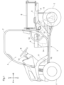
- Fig. 1 which shows arrow F to indicate the forward side of the body, arrow B to indicate the backward side of the body, arrow U to indicate the upward side of the body, and arrow D to indicate the downward side of the body.
- the front side of Fig. 1 corresponds to the leftward side of the body, whereas the back side of Fig. 1 corresponds to the rightward side of the body.
- the left-right direction of the body corresponds to the width direction of the body.
- Fig. 1 illustrates a utility vehicle for multiple purposes such as cargo transport and recreation.
- the utility vehicle includes a pair of left and right front wheels 1 as a travel device, a pair of left and right rear wheels 2 as a travel device, and a body 3 provided with the front and rear wheels 1 and 2.
- the front wheels 1 are turnable and drivable, whereas the rear wheels 2 are drivable.
- the utility vehicle includes a driver section 4 disposed at a front portion of the body 3 and configured to accommodate a driver.
- the utility vehicle includes in the driver section 4 a driver's seat 5, a steering wheel 6 for use to change the direction of the front wheels 1, a roll-over protective structure (ROPS) 7 that defines a driver space, an accelerator pedal 16 as an acceleration operating member for use to change the travel speed; a brake pedal 17 for use to operate a wheel brake; a hand brake lever 18 for use to operate a parking brake; and a shift lever 19 for shifting gears.
- the acceleration operating member is not necessarily an accelerator pedal 16, and may alternatively be any other operation member such as an accelerator lever.
- the utility vehicle includes a cargo box 8 backward of the driver section 4 and a body frame 9 holding the cargo box 8.
- the cargo box 8 is swingable up and down about a coupling axis P for the cargo box 8 and the body frame 9.
- the cargo box 8 is capable of being lifted into a dumping orientation and lowered into a travel orientation.
- the utility vehicle includes an electric motor 12 (which is an example of the "driving source"), an inverter 13, and two batteries 14 to drive the front and rear wheels 1 and 2.
- the electric motor 12 may be replaced with an e-Axle further including a transmission mechanism.
- the inverter 13 may be included in the e-Axle.
- the batteries 14 feed electric power to the inverter 13, which then converts it into alternating-current electricity.
- the inverter 13 supplies the alternating-current electricity (that is, a driving signal 22) to the electric motor 12 to drive the electric motor 12.
- the electric motor 12 is operable at a number of revolutions which number corresponds to the electric power supplied from the inverter 13 in accordance with the driving signal 22 (see Fig. 2 ).
- the electric motor 12 transmits its motive power to the transmission case 11.
- the motive power is then varied by a transmission (not illustrated in the drawings) in the transmission case 11.
- the transmission outputs the varied motive power from a rear-wheel differential mechanism (not illustrated in the drawings) in the transmission case 11 to the rear wheels 2.
- the transmission also outputs the varied motive power to the front wheels 1.
- the utility vehicle includes an electronic control unit (ECU) 21 including a processor such as a central processing unit (CPU).
- the ECU 21 is configured to generate a driving signal 22 for controlling the inverter 13.
- the ECU 21 generates a driving signal 22 in response to the accelerator pedal 16 receiving an operation and in accordance with an acceleration signal 23 corresponding to the amount of the operation of the accelerator pedal 16.
- the utility vehicle includes an accelerator sensor 24 configured to detect the amount of the operation of the accelerator pedal 16 (that is, the acceleration signal 23).
- the utility vehicle may be configured to detect the amount in any manner.
- the ECU 21 alleviates the influence of disturbance on the acceleration signal 23 in generating a driving signal 22.
- the ECU 21 attenuates the change of the driving signal 22 for the amount of a change of the acceleration signal 23 in accordance with the acceleration 25 to prevent the driving signal 22 from changing greatly (that is, to reduce the amount of a change of the driving signal 22) in response to a change of the acceleration signal 23 if the acceleration 25 is large.
- the utility vehicle includes an acceleration sensor 26 (which is an example of the "acceleration detector") configured to detect the vertical acceleration 25 of the body 3 relative to the ground.
- an acceleration sensor 26 (which is an example of the "acceleration detector") configured to detect the vertical acceleration 25 of the body 3 relative to the ground.
- the ECU 21 includes an input section 29, a constant determiner 31, a drive controller 33, and a storage 35.
- the input section 29 is configured to receive various items of information and signals inputted to the ECU 21.
- the input section 29 receives, for example, an acceleration signal 23 from the accelerator sensor 24 and information on the acceleration 25 that the acceleration sensor 26 has detected.
- the drive controller 33 is configured to generate a driving signal 22 on the basis of the acceleration signal 23 and the acceleration 25.
- the drive controller 33 generates a driving signal 22 basically in correspondence with the acceleration signal 23 (that is, the amount of the operation of the accelerator pedal 16).
- the amount of the operation of the accelerator pedal 16 may, however, be changed more than intended (operated) by the driver as a result of the influence of disturbance such as a shake of the body 3.
- the drive controller 33 uses a low pass filter to reduce the influence of disturbance in generating a driving signal 22 and thereby prevent the electric motor 12 from operating (that is, the travel speed from changing) as above as unintended by the driver.
- the constant determiner 31 is configured to adjust the time constant 37 for the low pass filter in accordance with disturbance.
- the time constant 37 is preset for the relationship between the acceleration signal 23 and the driving signal 22, and is stored in the storage 35. Adjusting the time constant 37 helps reduce the influence of disturbance in generating a driving signal 22.
- the storage 35 is configured to store various items of information such as the acceleration signal 23 and information on the acceleration 25 received by the input section 29, information on the time constant 37 determined by the constant determiner 31, and the driving signal 22 generated by the drive controller 33.
- the input section 29 continuously receives an acceleration signal 23 from the accelerator sensor 24 and stores the acceleration signal 23 in the storage 35 (see step #1 in Fig. 4 ).
- the input section 29 also continuously receives information on the acceleration 25 from the acceleration sensor 26 and stores the information in the storage 35 (see step #2 in Fig. 4 ).
- the constant determiner 31 adjusts the time constant 37 for the low pass filter in accordance with the acceleration signal 23 stored in the storage 35 (see step #3 in Fig. 4 ). Specifically, the constant determiner 31 increases the time constant 37 with an increase in the amount of a change of the acceleration signal 23. This prevents a driving signal 22 to be generated from changing greatly (that is, allows the driving signal 22 to change gently) in response to a great change of the acceleration signal 23 due to, for example, the influence of disturbance, thereby preventing the driving signal 22 (that is, the operation of the electric motor 12 or the travel speed) from changing rapidly.
- the drive controller 33 or the constant determiner 31 determines whether the acceleration 25 is equal to or larger than a reference acceleration 38 preset and stored in the storage 35 (see step #4 in Fig. 4 ).
- the constant determiner 31 further adjusts the time constant 37 for the low pass filter in accordance with the acceleration 25 stored in the storage 35 (see step #5 in Fig. 4 ). Specifically, the constant determiner 31 decreases the time constant 37 as the acceleration 25 increases. This prevents a driving signal 22 to be generated from changing greatly in response to a frequent change of the acceleration signal 23 due to the influence of a shake of the body 3, thereby reducing the influence on the driving signal 22 (that is, the operation of the electric motor 12 or the travel speed).
- the drive controller 33 generates a driving signal 22 on the basis of the acceleration signal 23 and the time constant 37. Specifically, the drive controller 33 uses a low pass filter based on the time constant 37 in the storage 35 for the change of the acceleration signal 23 to generate a driving signal 22 on the basis of the acceleration signal 23 as well as the amount of the change of the acceleration signal 23 (see step #6 in Fig. 4 ). If the acceleration 25 is smaller than the reference acceleration 38 (No in step #4 in Fig. 4 ), the drive controller 33 generates a driving signal 22 with use of the time constant 37 as adjusted in step #3 so that the driving signal 22 is not based on the acceleration 25.
- the drive controller 33 transmits the driving signal 22 to the inverter 13 (see step #7 in Fig. 4 ).
- the inverter 13 controls the electric motor 12 in accordance with the driving signal 22, so that the utility vehicle travels as driven by the electric motor 12.
- the drive controller 33 adjusts the time constant 37 for the low pass filter in accordance with the amount of a change of the acceleration signal 23, and thereby allows the amount of a change of the driving signal 22 to decrease with an increase in the amount of the change of the acceleration signal 23. With this configuration, the drive controller 33 prevents the driving signal 22 from changing extremely in response to an increase in the amount of a change of the acceleration signal 23.
- the drive controller 33 further adjusts the time constant 37 for the low pass filter in accordance with the acceleration 25, that is, decreases the time constant 37 as the acceleration 25 increases.
- the drive controller 33 may adjust the time constant 37 in accordance with the acceleration 25 in a continuous or stepwise manner. This configuration allows the drive controller 33 to determine if the acceleration 25 is large that the operation of the accelerator pedal 16 is being influenced by a shake of the body 3 and reduce the amount of a change of the driving signal 22. This allows the drive controller 33 to reduce the influence of a shake or vibration of the body 3 on the accelerator pedal 16.
- the above configuration allows the drive controller 33 to (i) generate a driving signal 22 with a reduced change amount if the amount of a change of the acceleration signal 23 is large to prevent the travel speed from changing rapidly and (ii) decrease the time constant 37 in response to a large shake of the body 3 to keep the driving signal 22 (that is, the travel speed) changeable responsively to an operation of the accelerator pedal 16.
- This allows the drive controller 33 to reduce the influence of disturbance such as a shake of the body 3 to control the travel speed accurately in accordance with the driver's intention.
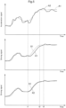
- the description below deals with a driving signal 22 generated on the basis of the amount of a change of the acceleration signal 23 and the acceleration 25, with reference to Figs. 2 and 5 .
- Fig. 5 shows line A1 to indicate a change over time of an acceleration signal 23 intended by the driver and line A2 to indicate a change over time of an acceleration signal 23 actually detected by the accelerator sensor 24.
- Line A2 indicates that the acceleration signal 23 is deviated from the driver's intention due to, for example, a shake of the body 3.
- Line S1 indicates a change over time of a driving signal 22 corresponding to the acceleration signal 23 intended by the driver.
- Line X1 indicates a change over time of a driving signal 22 generated on the basis of a time constant 37 not based on the acceleration 25.
- Line X2 indicates a change over time of a driving signal 22 generated on the basis of a time constant 37 based on the acceleration 25.
- Line X1 indicates a reduced vibration in the driving signal 22 as a result of a reduced vibration in the acceleration signal 23 indicated with line A2, but also indicates a delay in the change of the driving signal 22 relative to a change of the acceleration signal 23.
- Line X2 in contrast, indicates a reduced delay in the change of the driving signal 22 relative to a change of the acceleration signal 23.
- the acceleration signal 23 intended by the driver (A1) has an upward trend, whereas the actual acceleration signal 23 has a downward trend due to a shake of the body 3.
- the acceleration signal 23 intended by the driver (A1) finishes its increase at time point t2
- the driving signal 22 generated not on the basis of the acceleration 25 (X1) has a delay in its increase and does not finish its increase until time point t3.
- the driving signal 22 generated on the basis of the acceleration 25 (X2) changes more responsively to a change of the acceleration signal 23, and has a reduced delay relative to the driver's intention.
- generating a driving signal 22 on the basis of the amount of a change of the acceleration signal 23 and the acceleration 25 reduces the influence of disturbance on the amount of the change of the acceleration signal 23, and allows the driving signal 22 to be more responsive. This in turn makes it possible to control the travel speed accurately in accordance with the driver's intention.
- the present invention is applicable to any utility vehicle configured to travel in response to an accelerator operation and any of various work machines.
Landscapes
- Engineering & Computer Science (AREA)
- Mechanical Engineering (AREA)
- Automation & Control Theory (AREA)
- Human Computer Interaction (AREA)
- Transportation (AREA)
- Electric Propulsion And Braking For Vehicles (AREA)
- Control Of Driving Devices And Active Controlling Of Vehicle (AREA)
Abstract
Included are: a body; a travel device provided for the body; a driving source 12 configured to drive the travel device; an acceleration operating member 16 configured to receive an operation for adjusting a travel speed of the utility vehicle; a drive controller 33 configured to generate a driving signal 22 for the driving source; and an acceleration detector 26 configured to detect a vertical acceleration 25 of the body relative to ground, the drive controller 33 being configured to generate the driving signal 22 based on (i) an amount of the operation that the acceleration operating member 16 receives and (ii) the acceleration 25.
Description
- The present invention relates to a utility vehicle configured to travel in response to an accelerator operation.
- As disclosed in
Patent Literature 1, utility vehicles travel as driven by a driving source such as an engine or an electric motor. Utility vehicles travel at speeds based on an operation of an accelerator pedal (that is, an acceleration operating member) such that the driving source is controlled in accordance with a signal (that is, a driving signal) corresponding to the amount of the operation of the accelerator pedal. - Utility vehicles may travel on bad roads such as rough terrain. Such travel may cause the vehicle body to shake (or vibrate) vertically and thereby cause the driver's foot on the accelerator pedal to shake. This may in turn cause the accelerator pedal to be operated greatly and thereby change the travel speed greatly as unintended by the driver.
- Patent Literature
-
JP 2018-154191 A - The present invention has an object of providing a utility vehicle configured to travel at speeds accurately controllable in accordance with the driver's intention.
- In order to attain the above object, a utility vehicle as an embodiment of the present invention includes: a body; a travel device provided for the body; a driving source configured to drive the travel device; an acceleration operating member configured to receive an operation for adjusting a travel speed of the utility vehicle; a drive controller configured to generate a driving signal for the driving source; and an acceleration detector configured to detect a vertical acceleration of the body relative to ground, the drive controller being configured to generate the driving signal based on (i) an amount of the operation that the acceleration operating member receives and (ii) the acceleration.
- The above configuration allows that the driving signal is generated on the basis of the amount of an operation that the acceleration operating member receives , and the acceleration (that is, a shake of the body) is taken into consideration. This reduces the amount of a change of the driving signal in response to a great change in the amount of the operation of the acceleration operating member if a large shake of the body has caused the acceleration detector to detect a large vertical acceleration. This prevents the travel speed from being changed as unintended by the driver in response to an erroneous operation of the acceleration operating member due to a shake of the body, and thereby makes it possible to control the travel speed accurately in accordance with the driver's intention.
- The utility vehicle may be further configured such that the drive controller changes the driving signal in accordance with an amount of a change in the amount of the operation and attenuates the change of the driving signal for the amount of the change of the amount of the operation in accordance with the acceleration.
- The above configuration allows adjustment of how much the drive controller reduces the amount of a change of the driving signal in accordance with the level of the acceleration. This prevents the drive controller from reducing the amount of a change of the driving signal if the acceleration (that is, the vibration) is small and does not significantly influence the acceleration operating member, and allows the drive controller to reduce the amount of a change of the driving signal only if the vibration is so large as to influence the acceleration operating member. This in turn allows the travel speed to reflect the driver's intention more accurately, and thereby makes it possible to control the travel speed more accurately in accordance with the driver's intention.
- The utility vehicle may be further configured such that the drive controller attenuates the change of the driving signal for the amount of the operation with use of a low pass filter and adjusts a time constant for the low pass filter in accordance with the acceleration.
- The above configuration allows the drive controller to reduce the amount of a change of the driving signal if the amount of an operation of the acceleration operating member is large, thereby preventing a sharp change in the travel speed. The use of a low pass filter allows accurate reduction in the amount of a change of the driving signal. Adjusting the time constant for the low pass filter in accordance with the acceleration allows the amount of a change of the driving signal to be reduced on the basis of the acceleration. This makes it possible to control the travel speed more accurately in accordance with the driver's intention.
- The utility vehicle may be further configured such that the drive controller decreases the time constant as the acceleration increases.
- The above configuration allows the drive controller to reduce the amount of a change of the driving signal further as the acceleration increases. This reduces the influence of a shake of the body accurately, and thereby makes it possible to control the travel speed more accurately in accordance with the driver's intention.
- The utility vehicle may be further configured such that the acceleration detector is an acceleration sensor.
- The above configuration allows accurate detection of the acceleration, and thereby makes it possible to control the travel speed accurately in accordance with the driver's intention.
- The utility vehicle may further include: a suspension configured to alleviate a vertical vibration transmitted from the ground to the body, wherein the acceleration detector includes: a stroke detector configured to detect a stroke of the suspension; and a calculator configured to differentiate the stroke twice and provide a value resulting from the differentiation as the acceleration.
- Suspensions alleviate vibrations transmitted to the body. A suspension stroke allows prediction of a vertical vibration of the body. Differentiating the stroke twice provides the acceleration. This in turn makes it possible to control the travel speed accurately in accordance with the driver's intention.
- The utility vehicle may be further configured such that the driving source is an electric motor, the utility vehicle further includes an inverter configured to supply electric power to the electric motor, the driving signal serves to control the electric power, which the inverter outoputs, the electric motor is operable at a number of revolutions which number corresponds to the electric power outputted from the inverter in accordance with the driving signal, and the drive controller generates the driving signal based on the amount of the operation and the acceleration.
- The above configuration prevents the travel speed of an electrically operated utility vehicle from being changed as unintended by the driver in response to an erroneous operation of the acceleration operating member due to a shake of the body, and thereby makes it possible to control the travel speed accurately in accordance with the driver's intention.
-
-
Fig. 1 is a left side view of a utility vehicle. -
Fig. 2 is a diagram illustrating an example configuration for controlling a driving signal. -
Fig. 3 is a diagram illustrating an example data flow for controlling a driving signal. -
Fig. 4 is a flowchart of an example process of controlling a driving signal. -
Fig. 5 shows graphs for a description of a driving signal generated on the basis of an acceleration signal. - The description below deals with an electrically operated utility vehicle as an example of the utility vehicle of the present invention with reference to drawings. The description below refers to
Fig. 1 , which shows arrow F to indicate the forward side of the body, arrow B to indicate the backward side of the body, arrow U to indicate the upward side of the body, and arrow D to indicate the downward side of the body. The front side ofFig. 1 corresponds to the leftward side of the body, whereas the back side ofFig. 1 corresponds to the rightward side of the body. The left-right direction of the body corresponds to the width direction of the body. -
Fig. 1 illustrates a utility vehicle for multiple purposes such as cargo transport and recreation. The utility vehicle includes a pair of left and rightfront wheels 1 as a travel device, a pair of left and rightrear wheels 2 as a travel device, and abody 3 provided with the front andrear wheels front wheels 1 are turnable and drivable, whereas therear wheels 2 are drivable. - The utility vehicle includes a
driver section 4 disposed at a front portion of thebody 3 and configured to accommodate a driver. The utility vehicle includes in the driver section 4 a driver'sseat 5, asteering wheel 6 for use to change the direction of thefront wheels 1, a roll-over protective structure (ROPS) 7 that defines a driver space, anaccelerator pedal 16 as an acceleration operating member for use to change the travel speed; abrake pedal 17 for use to operate a wheel brake; ahand brake lever 18 for use to operate a parking brake; and ashift lever 19 for shifting gears. The acceleration operating member is not necessarily anaccelerator pedal 16, and may alternatively be any other operation member such as an accelerator lever. - The utility vehicle includes a
cargo box 8 backward of thedriver section 4 and abody frame 9 holding thecargo box 8. Thecargo box 8 is swingable up and down about a coupling axis P for thecargo box 8 and thebody frame 9. Thecargo box 8 is capable of being lifted into a dumping orientation and lowered into a travel orientation. - As illustrated in
Fig. 1 , the utility vehicle includes an electric motor 12 (which is an example of the "driving source"), aninverter 13, and twobatteries 14 to drive the front andrear wheels electric motor 12 may be replaced with an e-Axle further including a transmission mechanism. Theinverter 13 may be included in the e-Axle. - The
batteries 14 feed electric power to theinverter 13, which then converts it into alternating-current electricity. Theinverter 13 supplies the alternating-current electricity (that is, a driving signal 22) to theelectric motor 12 to drive theelectric motor 12. Theelectric motor 12 is operable at a number of revolutions which number corresponds to the electric power supplied from theinverter 13 in accordance with the driving signal 22 (seeFig. 2 ). Theelectric motor 12 transmits its motive power to thetransmission case 11. The motive power is then varied by a transmission (not illustrated in the drawings) in thetransmission case 11. The transmission outputs the varied motive power from a rear-wheel differential mechanism (not illustrated in the drawings) in thetransmission case 11 to therear wheels 2. The transmission also outputs the varied motive power to thefront wheels 1. - The description below deals with how the wheels are driven in response to an operation of the
accelerator pedal 16, with reference toFigs. 2 and3 . - The utility vehicle includes an electronic control unit (ECU) 21 including a processor such as a central processing unit (CPU). The
ECU 21 is configured to generate a drivingsignal 22 for controlling theinverter 13. TheECU 21 generates a drivingsignal 22 in response to theaccelerator pedal 16 receiving an operation and in accordance with anacceleration signal 23 corresponding to the amount of the operation of theaccelerator pedal 16. The utility vehicle includes anaccelerator sensor 24 configured to detect the amount of the operation of the accelerator pedal 16 (that is, the acceleration signal 23). The utility vehicle may be configured to detect the amount in any manner. - The
ECU 21 alleviates the influence of disturbance on theacceleration signal 23 in generating a drivingsignal 22. TheECU 21, to that end, detects theacceleration 25 of thebody 3 and generates a drivingsignal 22 on the basis of the acceleration signal 23 (that is, the amount of the operation of the accelerator pedal 16) and theacceleration 25. Specifically, theECU 21 attenuates the change of the drivingsignal 22 for the amount of a change of theacceleration signal 23 in accordance with theacceleration 25 to prevent the drivingsignal 22 from changing greatly (that is, to reduce the amount of a change of the driving signal 22) in response to a change of theacceleration signal 23 if theacceleration 25 is large. - To perform the above operation, the utility vehicle, as illustrated in
Figs. 2 and3 , includes an acceleration sensor 26 (which is an example of the "acceleration detector") configured to detect thevertical acceleration 25 of thebody 3 relative to the ground. - The
ECU 21 includes aninput section 29, aconstant determiner 31, adrive controller 33, and astorage 35. - The
input section 29 is configured to receive various items of information and signals inputted to theECU 21. Theinput section 29 receives, for example, anacceleration signal 23 from theaccelerator sensor 24 and information on theacceleration 25 that theacceleration sensor 26 has detected. - The
drive controller 33 is configured to generate a drivingsignal 22 on the basis of theacceleration signal 23 and theacceleration 25. Thedrive controller 33 generates a drivingsignal 22 basically in correspondence with the acceleration signal 23 (that is, the amount of the operation of the accelerator pedal 16). The amount of the operation of theaccelerator pedal 16 may, however, be changed more than intended (operated) by the driver as a result of the influence of disturbance such as a shake of thebody 3. Thedrive controller 33 uses a low pass filter to reduce the influence of disturbance in generating a drivingsignal 22 and thereby prevent theelectric motor 12 from operating (that is, the travel speed from changing) as above as unintended by the driver. - The
constant determiner 31 is configured to adjust thetime constant 37 for the low pass filter in accordance with disturbance. Thetime constant 37 is preset for the relationship between theacceleration signal 23 and the drivingsignal 22, and is stored in thestorage 35. Adjusting thetime constant 37 helps reduce the influence of disturbance in generating a drivingsignal 22. - The
storage 35 is configured to store various items of information such as theacceleration signal 23 and information on theacceleration 25 received by theinput section 29, information on thetime constant 37 determined by theconstant determiner 31, and the drivingsignal 22 generated by thedrive controller 33. - The description below deals with a flow of generating a driving
signal 22, with reference toFigs. 2 to 4 . - First, the
input section 29 continuously receives anacceleration signal 23 from theaccelerator sensor 24 and stores theacceleration signal 23 in the storage 35 (seestep # 1 inFig. 4 ). Theinput section 29 also continuously receives information on theacceleration 25 from theacceleration sensor 26 and stores the information in the storage 35 (seestep # 2 inFig. 4 ). - Next, the
constant determiner 31 adjusts thetime constant 37 for the low pass filter in accordance with theacceleration signal 23 stored in the storage 35 (seestep # 3 inFig. 4 ). Specifically, theconstant determiner 31 increases thetime constant 37 with an increase in the amount of a change of theacceleration signal 23. This prevents a drivingsignal 22 to be generated from changing greatly (that is, allows the drivingsignal 22 to change gently) in response to a great change of theacceleration signal 23 due to, for example, the influence of disturbance, thereby preventing the driving signal 22 (that is, the operation of theelectric motor 12 or the travel speed) from changing rapidly. - Next, the
drive controller 33 or theconstant determiner 31 determines whether theacceleration 25 is equal to or larger than areference acceleration 38 preset and stored in the storage 35 (seestep # 4 inFig. 4 ). - If the
acceleration 25 is equal to or larger than the reference acceleration 38 (Yes instep # 4 inFig. 4 ), theconstant determiner 31 further adjusts thetime constant 37 for the low pass filter in accordance with theacceleration 25 stored in the storage 35 (seestep # 5 inFig. 4 ). Specifically, theconstant determiner 31 decreases thetime constant 37 as theacceleration 25 increases. This prevents a drivingsignal 22 to be generated from changing greatly in response to a frequent change of theacceleration signal 23 due to the influence of a shake of thebody 3, thereby reducing the influence on the driving signal 22 (that is, the operation of theelectric motor 12 or the travel speed). - Next, the
drive controller 33 generates a drivingsignal 22 on the basis of theacceleration signal 23 and thetime constant 37. Specifically, thedrive controller 33 uses a low pass filter based on thetime constant 37 in thestorage 35 for the change of theacceleration signal 23 to generate a drivingsignal 22 on the basis of theacceleration signal 23 as well as the amount of the change of the acceleration signal 23 (seestep # 6 inFig. 4 ). If theacceleration 25 is smaller than the reference acceleration 38 (No instep # 4 inFig. 4 ), thedrive controller 33 generates a drivingsignal 22 with use of thetime constant 37 as adjusted instep # 3 so that the drivingsignal 22 is not based on theacceleration 25. - Next, the
drive controller 33 transmits the drivingsignal 22 to the inverter 13 (seestep # 7 inFig. 4 ). Theinverter 13 controls theelectric motor 12 in accordance with the drivingsignal 22, so that the utility vehicle travels as driven by theelectric motor 12. - As described above, the
drive controller 33 adjusts thetime constant 37 for the low pass filter in accordance with the amount of a change of theacceleration signal 23, and thereby allows the amount of a change of the drivingsignal 22 to decrease with an increase in the amount of the change of theacceleration signal 23. With this configuration, thedrive controller 33 prevents the drivingsignal 22 from changing extremely in response to an increase in the amount of a change of theacceleration signal 23. - The
drive controller 33 further adjusts thetime constant 37 for the low pass filter in accordance with theacceleration 25, that is, decreases thetime constant 37 as theacceleration 25 increases. Thedrive controller 33 may adjust thetime constant 37 in accordance with theacceleration 25 in a continuous or stepwise manner. This configuration allows thedrive controller 33 to determine if theacceleration 25 is large that the operation of theaccelerator pedal 16 is being influenced by a shake of thebody 3 and reduce the amount of a change of the drivingsignal 22. This allows thedrive controller 33 to reduce the influence of a shake or vibration of thebody 3 on theaccelerator pedal 16. - The above configuration allows the
drive controller 33 to (i) generate a drivingsignal 22 with a reduced change amount if the amount of a change of theacceleration signal 23 is large to prevent the travel speed from changing rapidly and (ii) decrease thetime constant 37 in response to a large shake of thebody 3 to keep the driving signal 22 (that is, the travel speed) changeable responsively to an operation of theaccelerator pedal 16. This in turn allows thedrive controller 33 to reduce the influence of disturbance such as a shake of thebody 3 to control the travel speed accurately in accordance with the driver's intention. - The description below deals with a driving
signal 22 generated on the basis of the amount of a change of theacceleration signal 23 and theacceleration 25, with reference toFigs. 2 and5 . -
Fig. 5 shows line A1 to indicate a change over time of anacceleration signal 23 intended by the driver and line A2 to indicate a change over time of anacceleration signal 23 actually detected by theaccelerator sensor 24. Line A2 indicates that theacceleration signal 23 is deviated from the driver's intention due to, for example, a shake of thebody 3. Line S1 indicates a change over time of a drivingsignal 22 corresponding to theacceleration signal 23 intended by the driver. - Line X1 indicates a change over time of a driving
signal 22 generated on the basis of atime constant 37 not based on theacceleration 25. Line X2 indicates a change over time of a drivingsignal 22 generated on the basis of atime constant 37 based on theacceleration 25. - Line X1 indicates a reduced vibration in the driving
signal 22 as a result of a reduced vibration in theacceleration signal 23 indicated with line A2, but also indicates a delay in the change of the drivingsignal 22 relative to a change of theacceleration signal 23. Line X2, in contrast, indicates a reduced delay in the change of the drivingsignal 22 relative to a change of theacceleration signal 23. - At time point t1, for instance, the
acceleration signal 23 intended by the driver (A1) has an upward trend, whereas theactual acceleration signal 23 has a downward trend due to a shake of thebody 3. As a result, theacceleration signal 23 intended by the driver (A1) finishes its increase at time point t2, whereas the drivingsignal 22 generated not on the basis of the acceleration 25 (X1) has a delay in its increase and does not finish its increase until time point t3. - In contrast, the driving
signal 22 generated on the basis of the acceleration 25 (X2) changes more responsively to a change of theacceleration signal 23, and has a reduced delay relative to the driver's intention. - As described above, generating a driving
signal 22 on the basis of the amount of a change of theacceleration signal 23 and theacceleration 25 reduces the influence of disturbance on the amount of the change of theacceleration signal 23, and allows the drivingsignal 22 to be more responsive. This in turn makes it possible to control the travel speed accurately in accordance with the driver's intention. -
- (1) The embodiment described above may be altered to detect the
acceleration 25 of thebody 3 with use of any acceleration detector other than theacceleration sensor 26. The embodiment may, for instance, include a suspension (not illustrated in the drawings) configured to alleviate vertical vibrations transmitted from the ground to thebody 3 and be configured to detect theacceleration 25 on the basis of a stroke of the suspension. The acceleration detector, in this case, includes a stroke detector configured to detect a stroke of the suspension and a calculator configured to differentiate the stroke twice and provide the resulting value as theacceleration 25. This facilitates detecting theacceleration 25 in accordance with the configuration of the utility vehicle. - (2) The embodiments described above may each be altered such that the
drive controller 33 uses only theacceleration 25 but not the amount of a change of theacceleration signal 23 to reduce the influence of disturbance. Theconstant determiner 31 may, in this case, increase thetime constant 37 as theacceleration 25 increases. This allows use of a simple configuration to generate a drivingsignal 22 for control of the travel speed. - (3) The embodiments described above may each be altered to use no
reference acceleration 38 so that theconstant determiner 31 adjusts thetime constant 37 in accordance with theacceleration 25 regardless of its level. This allows use of a simple configuration to generate a drivingsignal 22 for control of the travel speed. - (4) The embodiments described above may each be altered such that the
drive controller 33 uses an element other than a low pass filter to reduce the influence of disturbance. - (5) The embodiments described above may each be altered such that the
ECU 21 includes functional blocks other than those described above. The functional blocks of theECU 21 may, for instance, each be divided further, or a portion of or the entire functional block may be combined with another functional block. TheECU 21 may include an additional functional block for an operation other than braking the utility vehicle, or may be dedicated to generating a drivingsignal 22. TheECU 21 may function with use of functional blocks other than those described above. Further, one or more or all of the functions of theECU 21 may be performed by software. Programs as such software are stored in a storage device such as thestorage 35 and executed by a processor included in theECU 21 such as a CPU or a separate processor. - (6) The utility vehicle may include an engine instead of the
electric motor 12 as its driving source. The utility vehicle may be a hybrid vehicle drivable by theelectric motor 12 and an engine. - (7) The utility vehicle may be provided with an implement, and may be an agricultural work machine such as a tractor or a mower, or another work machine for performing any of various types of work.
- The present invention is applicable to any utility vehicle configured to travel in response to an accelerator operation and any of various work machines.
-
- 1
- Front wheel (travel device)
- 2
- Rear wheel (travel device)
- 3
- Body
- 12
- Electric motor (driving source)
- 13
- Inverter
- 16
- Accelerator pedal (acceleration operating member)
- 22
- Driving signal
- 23
- Acceleration signal (amount of operation)
- 24
- Accelerator sensor
- 25
- Acceleration
- 26
- Acceleration sensor (acceleration detector)
- 33
- Drive controller
- 37
- Time constant
Claims (7)
- A utility vehicle, comprising:a body (3);a travel device (1, 2) provided for the body (3);a driving source (12) configured to drive the travel device (1, 2) ;an acceleration operating member (16) configured to receive an operation for adjusting a travel speed of the utility vehicle;a drive controller (33) configured to generate a driving signal (22) for the driving source (12); andan acceleration detector (26) configured to detect a vertical acceleration (25) of the body (3) relative to ground,the drive controller (33) being configured to generate the driving signal (22) based on (i) an amount of the operation that the acceleration operating member (16) receives and (ii) the acceleration (25).
- The utility vehicle according to claim 1, wherein
the drive controller (33) is configured to change the driving signal (22) in accordance with an amount of a change in the amount of the operation and attenuates the change of the driving signal (22) for the amount of the change of the amount of the operation in accordance with the acceleration (25). - The utility vehicle according to claim 2, wherein
the drive controller (33) is configured to attenuate the change of the driving signal (22) for the amount of the operation with use of a low pass filter and adjusts a time constant for the low pass filter in accordance with the acceleration. - The utility vehicle according to claim 3, wherein
the drive controller (33) is configured to decrease the time constant as the acceleration increases. - The utility vehicle according to any one of claims 1 to 4, wherein
the acceleration detector (26) is an acceleration sensor. - The utility vehicle according to any one of claims 1 to 4, further comprising:a suspension configured to alleviate a vertical vibration transmitted from the ground to the body (3),wherein the acceleration detector (26) includes:a stroke detector configured to detect a stroke of the suspension; anda calculator configured to differentiate the stroke twice and provide a value resulting from the differentiation as the acceleration (25).
- The utility vehicle according to any one of claims 1 to 6, whereinthe driving source (12) is an electric motor,the utility vehicle further comprisesan inverter (13) configured to supply electric power to the electric motor (12), the inverter (13) being controlled by the driving signal (22) so as to control the electric power, which the inverter (13) outputs,the electric motor (12) is operable at a number of revolutions which number corresponds to the electric power outputted from the inverter (13) in accordance with the driving signal (22), andthe drive controller (33) is configured to generate the driving signal (22) based on the amount of the operation and the acceleration (25).
Applications Claiming Priority (1)
| Application Number | Priority Date | Filing Date | Title |
|---|---|---|---|
| JP2023135277A JP2025030195A (en) | 2023-08-23 | 2023-08-23 | Multi-purpose vehicles |
Publications (1)
| Publication Number | Publication Date |
|---|---|
| EP4512682A1 true EP4512682A1 (en) | 2025-02-26 |
Family
ID=91953771
Family Applications (1)
| Application Number | Title | Priority Date | Filing Date |
|---|---|---|---|
| EP24188864.3A Pending EP4512682A1 (en) | 2023-08-23 | 2024-07-16 | Utility vehicle |
Country Status (3)
| Country | Link |
|---|---|
| US (1) | US20250065685A1 (en) |
| EP (1) | EP4512682A1 (en) |
| JP (1) | JP2025030195A (en) |
Citations (5)
| Publication number | Priority date | Publication date | Assignee | Title |
|---|---|---|---|---|
| US20030070859A1 (en) * | 2001-10-12 | 2003-04-17 | Dahl Jeffery A. | Operation of wheeled work machine |
| US20110022286A1 (en) * | 2009-01-27 | 2011-01-27 | Honda Motor Co., Ltd. | Vehicle drive force control system |
| US20120143392A1 (en) * | 2010-12-03 | 2012-06-07 | Marc Lurie | Method and apparatus to adjust for undesired force influencing a vehicle input control |
| US20160082862A1 (en) * | 2014-09-22 | 2016-03-24 | Hyundai Motor Company | System and method of controlling motor for reducing vibration of electric vehicle |
| FR3047714A1 (en) * | 2016-02-12 | 2017-08-18 | Renault Sas | METHOD AND DEVICE FOR CORRECTING A TORQUE SET FOR MOTOR VEHICLE MOTOR |
-
2023
- 2023-08-23 JP JP2023135277A patent/JP2025030195A/en active Pending
-
2024
- 2024-07-16 EP EP24188864.3A patent/EP4512682A1/en active Pending
- 2024-08-22 US US18/811,951 patent/US20250065685A1/en active Pending
Patent Citations (5)
| Publication number | Priority date | Publication date | Assignee | Title |
|---|---|---|---|---|
| US20030070859A1 (en) * | 2001-10-12 | 2003-04-17 | Dahl Jeffery A. | Operation of wheeled work machine |
| US20110022286A1 (en) * | 2009-01-27 | 2011-01-27 | Honda Motor Co., Ltd. | Vehicle drive force control system |
| US20120143392A1 (en) * | 2010-12-03 | 2012-06-07 | Marc Lurie | Method and apparatus to adjust for undesired force influencing a vehicle input control |
| US20160082862A1 (en) * | 2014-09-22 | 2016-03-24 | Hyundai Motor Company | System and method of controlling motor for reducing vibration of electric vehicle |
| FR3047714A1 (en) * | 2016-02-12 | 2017-08-18 | Renault Sas | METHOD AND DEVICE FOR CORRECTING A TORQUE SET FOR MOTOR VEHICLE MOTOR |
Also Published As
| Publication number | Publication date |
|---|---|
| US20250065685A1 (en) | 2025-02-27 |
| JP2025030195A (en) | 2025-03-07 |
Similar Documents
| Publication | Publication Date | Title |
|---|---|---|
| US8718875B2 (en) | Vehicle motion control apparatus | |
| EP3342941B1 (en) | Control system for work vehicle, and control method for work vehicle | |
| CN113879131B (en) | Power transmission system of electric automobile | |
| US10532768B2 (en) | Method for controlling position of vehicle | |
| US7308350B2 (en) | Method and apparatus for determining adaptive brake gain parameters for use in a safety system of an automotive vehicle | |
| CN114450217B (en) | Steering assist device for straddle-type vehicles | |
| CN106553711A (en) | For controlling vehicle, the system and method for active air dynamic elements | |
| US6519523B2 (en) | Method and device for determining an unstable driving condition of a motor vehicle | |
| JP2019196082A (en) | Vehicular information display apparatus | |
| CN109895845A (en) | The method of the all-wheel control system and operation all-wheel control system of motor vehicles | |
| US20230035844A1 (en) | Electrically propelled two-wheeled vehicle and method for adjusting a drive torque of an electrically propelled two-wheeled vehicle | |
| JP2019534195A (en) | Vehicle control system and method | |
| US9919697B2 (en) | Work vehicle | |
| KR20140050395A (en) | Control method for lane keeping assist of vehicle and apparatus for lane keeping assist implementing the same | |
| JP2011088574A (en) | Vehicle controller | |
| US9031728B2 (en) | Electric driving type utility vehicle having regenerative brake force distribution control function, and regenerative brake force distribution control method thereof | |
| EP4512682A1 (en) | Utility vehicle | |
| CN114074547A (en) | System and method for off-road driving assistance for a vehicle | |
| CN117429543A (en) | Method for controlling electric drive of two-wheeled vehicle and control device for executing the method | |
| JP2002168620A (en) | Device for detecting roll angle of vehicle, and device for preventing roll-over | |
| EP4474204A1 (en) | Straddle vehicle and vehicle control method | |
| JP2005020830A (en) | Vehicle yawing behavior control device | |
| JP5387471B2 (en) | Control device for electric motor in left and right independent drive vehicle | |
| US6917869B2 (en) | Method of controlling the vehicle handling by means of measures for avoiding an understeering | |
| JP3039071B2 (en) | Vehicle turning limit judgment device |
Legal Events
| Date | Code | Title | Description |
|---|---|---|---|
| PUAI | Public reference made under article 153(3) epc to a published international application that has entered the european phase |
Free format text: ORIGINAL CODE: 0009012 |
|
| STAA | Information on the status of an ep patent application or granted ep patent |
Free format text: STATUS: REQUEST FOR EXAMINATION WAS MADE |
|
| 17P | Request for examination filed |
Effective date: 20240716 |
|
| AK | Designated contracting states |
Kind code of ref document: A1 Designated state(s): AL AT BE BG CH CY CZ DE DK EE ES FI FR GB GR HR HU IE IS IT LI LT LU LV MC ME MK MT NL NO PL PT RO RS SE SI SK SM TR |
|
| RIN1 | Information on inventor provided before grant (corrected) |
Inventor name: TANAKA, KAZUHIRO |
|
| STAA | Information on the status of an ep patent application or granted ep patent |
Free format text: STATUS: EXAMINATION IS IN PROGRESS |
|
| 17Q | First examination report despatched |
Effective date: 20260319 |