EP4512681A1 - A controller for a vehicle - Google Patents
A controller for a vehicle Download PDFInfo
- Publication number
- EP4512681A1 EP4512681A1 EP24200708.6A EP24200708A EP4512681A1 EP 4512681 A1 EP4512681 A1 EP 4512681A1 EP 24200708 A EP24200708 A EP 24200708A EP 4512681 A1 EP4512681 A1 EP 4512681A1
- Authority
- EP
- European Patent Office
- Prior art keywords
- accelerator pedal
- vehicle
- speed
- map
- controller
- Prior art date
- Legal status (The legal status is an assumption and is not a legal conclusion. Google has not performed a legal analysis and makes no representation as to the accuracy of the status listed.)
- Pending
Links
Images










Classifications
-
- B—PERFORMING OPERATIONS; TRANSPORTING
- B60—VEHICLES IN GENERAL
- B60W—CONJOINT CONTROL OF VEHICLE SUB-UNITS OF DIFFERENT TYPE OR DIFFERENT FUNCTION; CONTROL SYSTEMS SPECIALLY ADAPTED FOR HYBRID VEHICLES; ROAD VEHICLE DRIVE CONTROL SYSTEMS FOR PURPOSES NOT RELATED TO THE CONTROL OF A PARTICULAR SUB-UNIT
- B60W30/00—Purposes of road vehicle drive control systems not related to the control of a particular sub-unit, e.g. of systems using conjoint control of vehicle sub-units
- B60W30/14—Adaptive cruise control
- B60W30/143—Speed control
-
- B—PERFORMING OPERATIONS; TRANSPORTING
- B60—VEHICLES IN GENERAL
- B60W—CONJOINT CONTROL OF VEHICLE SUB-UNITS OF DIFFERENT TYPE OR DIFFERENT FUNCTION; CONTROL SYSTEMS SPECIALLY ADAPTED FOR HYBRID VEHICLES; ROAD VEHICLE DRIVE CONTROL SYSTEMS FOR PURPOSES NOT RELATED TO THE CONTROL OF A PARTICULAR SUB-UNIT
- B60W30/00—Purposes of road vehicle drive control systems not related to the control of a particular sub-unit, e.g. of systems using conjoint control of vehicle sub-units
- B60W30/18—Propelling the vehicle
- B60W30/18009—Propelling the vehicle related to particular drive situations
- B60W30/18109—Braking
- B60W30/18127—Regenerative braking
-
- B—PERFORMING OPERATIONS; TRANSPORTING
- B60—VEHICLES IN GENERAL
- B60L—PROPULSION OF ELECTRICALLY-PROPELLED VEHICLES; SUPPLYING ELECTRIC POWER FOR AUXILIARY EQUIPMENT OF ELECTRICALLY-PROPELLED VEHICLES; ELECTRODYNAMIC BRAKE SYSTEMS FOR VEHICLES IN GENERAL; MAGNETIC SUSPENSION OR LEVITATION FOR VEHICLES; MONITORING OPERATING VARIABLES OF ELECTRICALLY-PROPELLED VEHICLES; ELECTRIC SAFETY DEVICES FOR ELECTRICALLY-PROPELLED VEHICLES
- B60L15/00—Methods, circuits, or devices for controlling the traction-motor speed of electrically-propelled vehicles
- B60L15/20—Methods, circuits, or devices for controlling the traction-motor speed of electrically-propelled vehicles for control of the vehicle or its driving motor to achieve a desired performance, e.g. speed, torque, programmed variation of speed
-
- B—PERFORMING OPERATIONS; TRANSPORTING
- B60—VEHICLES IN GENERAL
- B60L—PROPULSION OF ELECTRICALLY-PROPELLED VEHICLES; SUPPLYING ELECTRIC POWER FOR AUXILIARY EQUIPMENT OF ELECTRICALLY-PROPELLED VEHICLES; ELECTRODYNAMIC BRAKE SYSTEMS FOR VEHICLES IN GENERAL; MAGNETIC SUSPENSION OR LEVITATION FOR VEHICLES; MONITORING OPERATING VARIABLES OF ELECTRICALLY-PROPELLED VEHICLES; ELECTRIC SAFETY DEVICES FOR ELECTRICALLY-PROPELLED VEHICLES
- B60L58/00—Methods or circuit arrangements for monitoring or controlling batteries or fuel cells, specially adapted for electric vehicles
- B60L58/10—Methods or circuit arrangements for monitoring or controlling batteries or fuel cells, specially adapted for electric vehicles for monitoring or controlling batteries
- B60L58/12—Methods or circuit arrangements for monitoring or controlling batteries or fuel cells, specially adapted for electric vehicles for monitoring or controlling batteries responding to state of charge [SoC]
-
- B—PERFORMING OPERATIONS; TRANSPORTING
- B60—VEHICLES IN GENERAL
- B60W—CONJOINT CONTROL OF VEHICLE SUB-UNITS OF DIFFERENT TYPE OR DIFFERENT FUNCTION; CONTROL SYSTEMS SPECIALLY ADAPTED FOR HYBRID VEHICLES; ROAD VEHICLE DRIVE CONTROL SYSTEMS FOR PURPOSES NOT RELATED TO THE CONTROL OF A PARTICULAR SUB-UNIT
- B60W40/00—Estimation or calculation of non-directly measurable driving parameters for road vehicle drive control systems not related to the control of a particular sub unit, e.g. by using mathematical models
- B60W40/02—Estimation or calculation of non-directly measurable driving parameters for road vehicle drive control systems not related to the control of a particular sub unit, e.g. by using mathematical models related to ambient conditions
- B60W40/06—Road conditions
-
- B—PERFORMING OPERATIONS; TRANSPORTING
- B60—VEHICLES IN GENERAL
- B60W—CONJOINT CONTROL OF VEHICLE SUB-UNITS OF DIFFERENT TYPE OR DIFFERENT FUNCTION; CONTROL SYSTEMS SPECIALLY ADAPTED FOR HYBRID VEHICLES; ROAD VEHICLE DRIVE CONTROL SYSTEMS FOR PURPOSES NOT RELATED TO THE CONTROL OF A PARTICULAR SUB-UNIT
- B60W50/00—Details of control systems for road vehicle drive control not related to the control of a particular sub-unit, e.g. process diagnostic or vehicle driver interfaces
- B60W50/08—Interaction between the driver and the control system
- B60W50/10—Interpretation of driver requests or demands
-
- B—PERFORMING OPERATIONS; TRANSPORTING
- B60—VEHICLES IN GENERAL
- B60L—PROPULSION OF ELECTRICALLY-PROPELLED VEHICLES; SUPPLYING ELECTRIC POWER FOR AUXILIARY EQUIPMENT OF ELECTRICALLY-PROPELLED VEHICLES; ELECTRODYNAMIC BRAKE SYSTEMS FOR VEHICLES IN GENERAL; MAGNETIC SUSPENSION OR LEVITATION FOR VEHICLES; MONITORING OPERATING VARIABLES OF ELECTRICALLY-PROPELLED VEHICLES; ELECTRIC SAFETY DEVICES FOR ELECTRICALLY-PROPELLED VEHICLES
- B60L2240/00—Control parameters of input or output; Target parameters
- B60L2240/10—Vehicle control parameters
- B60L2240/12—Speed
-
- B—PERFORMING OPERATIONS; TRANSPORTING
- B60—VEHICLES IN GENERAL
- B60L—PROPULSION OF ELECTRICALLY-PROPELLED VEHICLES; SUPPLYING ELECTRIC POWER FOR AUXILIARY EQUIPMENT OF ELECTRICALLY-PROPELLED VEHICLES; ELECTRODYNAMIC BRAKE SYSTEMS FOR VEHICLES IN GENERAL; MAGNETIC SUSPENSION OR LEVITATION FOR VEHICLES; MONITORING OPERATING VARIABLES OF ELECTRICALLY-PROPELLED VEHICLES; ELECTRIC SAFETY DEVICES FOR ELECTRICALLY-PROPELLED VEHICLES
- B60L2240/00—Control parameters of input or output; Target parameters
- B60L2240/60—Navigation input
- B60L2240/64—Road conditions
- B60L2240/642—Slope of road
-
- B—PERFORMING OPERATIONS; TRANSPORTING
- B60—VEHICLES IN GENERAL
- B60L—PROPULSION OF ELECTRICALLY-PROPELLED VEHICLES; SUPPLYING ELECTRIC POWER FOR AUXILIARY EQUIPMENT OF ELECTRICALLY-PROPELLED VEHICLES; ELECTRODYNAMIC BRAKE SYSTEMS FOR VEHICLES IN GENERAL; MAGNETIC SUSPENSION OR LEVITATION FOR VEHICLES; MONITORING OPERATING VARIABLES OF ELECTRICALLY-PROPELLED VEHICLES; ELECTRIC SAFETY DEVICES FOR ELECTRICALLY-PROPELLED VEHICLES
- B60L2250/00—Driver interactions
- B60L2250/26—Driver interactions by pedal actuation
- B60L2250/28—Accelerator pedal thresholds
-
- B—PERFORMING OPERATIONS; TRANSPORTING
- B60—VEHICLES IN GENERAL
- B60W—CONJOINT CONTROL OF VEHICLE SUB-UNITS OF DIFFERENT TYPE OR DIFFERENT FUNCTION; CONTROL SYSTEMS SPECIALLY ADAPTED FOR HYBRID VEHICLES; ROAD VEHICLE DRIVE CONTROL SYSTEMS FOR PURPOSES NOT RELATED TO THE CONTROL OF A PARTICULAR SUB-UNIT
- B60W50/00—Details of control systems for road vehicle drive control not related to the control of a particular sub-unit, e.g. process diagnostic or vehicle driver interfaces
- B60W2050/0001—Details of the control system
- B60W2050/0019—Control system elements or transfer functions
- B60W2050/0026—Lookup tables or parameter maps
-
- B—PERFORMING OPERATIONS; TRANSPORTING
- B60—VEHICLES IN GENERAL
- B60W—CONJOINT CONTROL OF VEHICLE SUB-UNITS OF DIFFERENT TYPE OR DIFFERENT FUNCTION; CONTROL SYSTEMS SPECIALLY ADAPTED FOR HYBRID VEHICLES; ROAD VEHICLE DRIVE CONTROL SYSTEMS FOR PURPOSES NOT RELATED TO THE CONTROL OF A PARTICULAR SUB-UNIT
- B60W2510/00—Input parameters relating to a particular sub-units
- B60W2510/24—Energy storage means
- B60W2510/242—Energy storage means for electrical energy
- B60W2510/244—Charge state
-
- B—PERFORMING OPERATIONS; TRANSPORTING
- B60—VEHICLES IN GENERAL
- B60W—CONJOINT CONTROL OF VEHICLE SUB-UNITS OF DIFFERENT TYPE OR DIFFERENT FUNCTION; CONTROL SYSTEMS SPECIALLY ADAPTED FOR HYBRID VEHICLES; ROAD VEHICLE DRIVE CONTROL SYSTEMS FOR PURPOSES NOT RELATED TO THE CONTROL OF A PARTICULAR SUB-UNIT
- B60W2520/00—Input parameters relating to overall vehicle dynamics
- B60W2520/10—Longitudinal speed
-
- B—PERFORMING OPERATIONS; TRANSPORTING
- B60—VEHICLES IN GENERAL
- B60W—CONJOINT CONTROL OF VEHICLE SUB-UNITS OF DIFFERENT TYPE OR DIFFERENT FUNCTION; CONTROL SYSTEMS SPECIALLY ADAPTED FOR HYBRID VEHICLES; ROAD VEHICLE DRIVE CONTROL SYSTEMS FOR PURPOSES NOT RELATED TO THE CONTROL OF A PARTICULAR SUB-UNIT
- B60W2540/00—Input parameters relating to occupants
- B60W2540/10—Accelerator pedal position
-
- B—PERFORMING OPERATIONS; TRANSPORTING
- B60—VEHICLES IN GENERAL
- B60W—CONJOINT CONTROL OF VEHICLE SUB-UNITS OF DIFFERENT TYPE OR DIFFERENT FUNCTION; CONTROL SYSTEMS SPECIALLY ADAPTED FOR HYBRID VEHICLES; ROAD VEHICLE DRIVE CONTROL SYSTEMS FOR PURPOSES NOT RELATED TO THE CONTROL OF A PARTICULAR SUB-UNIT
- B60W2552/00—Input parameters relating to infrastructure
-
- B—PERFORMING OPERATIONS; TRANSPORTING
- B60—VEHICLES IN GENERAL
- B60W—CONJOINT CONTROL OF VEHICLE SUB-UNITS OF DIFFERENT TYPE OR DIFFERENT FUNCTION; CONTROL SYSTEMS SPECIALLY ADAPTED FOR HYBRID VEHICLES; ROAD VEHICLE DRIVE CONTROL SYSTEMS FOR PURPOSES NOT RELATED TO THE CONTROL OF A PARTICULAR SUB-UNIT
- B60W2552/00—Input parameters relating to infrastructure
- B60W2552/15—Road slope, i.e. the inclination of a road segment in the longitudinal direction
-
- B—PERFORMING OPERATIONS; TRANSPORTING
- B60—VEHICLES IN GENERAL
- B60W—CONJOINT CONTROL OF VEHICLE SUB-UNITS OF DIFFERENT TYPE OR DIFFERENT FUNCTION; CONTROL SYSTEMS SPECIALLY ADAPTED FOR HYBRID VEHICLES; ROAD VEHICLE DRIVE CONTROL SYSTEMS FOR PURPOSES NOT RELATED TO THE CONTROL OF A PARTICULAR SUB-UNIT
- B60W2710/00—Output or target parameters relating to a particular sub-units
- B60W2710/08—Electric propulsion units
- B60W2710/083—Torque
-
- B—PERFORMING OPERATIONS; TRANSPORTING
- B60—VEHICLES IN GENERAL
- B60W—CONJOINT CONTROL OF VEHICLE SUB-UNITS OF DIFFERENT TYPE OR DIFFERENT FUNCTION; CONTROL SYSTEMS SPECIALLY ADAPTED FOR HYBRID VEHICLES; ROAD VEHICLE DRIVE CONTROL SYSTEMS FOR PURPOSES NOT RELATED TO THE CONTROL OF A PARTICULAR SUB-UNIT
- B60W2720/00—Output or target parameters relating to overall vehicle dynamics
- B60W2720/10—Longitudinal speed
-
- Y—GENERAL TAGGING OF NEW TECHNOLOGICAL DEVELOPMENTS; GENERAL TAGGING OF CROSS-SECTIONAL TECHNOLOGIES SPANNING OVER SEVERAL SECTIONS OF THE IPC; TECHNICAL SUBJECTS COVERED BY FORMER USPC CROSS-REFERENCE ART COLLECTIONS [XRACs] AND DIGESTS
- Y02—TECHNOLOGIES OR APPLICATIONS FOR MITIGATION OR ADAPTATION AGAINST CLIMATE CHANGE
- Y02T—CLIMATE CHANGE MITIGATION TECHNOLOGIES RELATED TO TRANSPORTATION
- Y02T10/00—Road transport of goods or passengers
- Y02T10/60—Other road transportation technologies with climate change mitigation effect
- Y02T10/64—Electric machine technologies in electromobility
-
- Y—GENERAL TAGGING OF NEW TECHNOLOGICAL DEVELOPMENTS; GENERAL TAGGING OF CROSS-SECTIONAL TECHNOLOGIES SPANNING OVER SEVERAL SECTIONS OF THE IPC; TECHNICAL SUBJECTS COVERED BY FORMER USPC CROSS-REFERENCE ART COLLECTIONS [XRACs] AND DIGESTS
- Y02—TECHNOLOGIES OR APPLICATIONS FOR MITIGATION OR ADAPTATION AGAINST CLIMATE CHANGE
- Y02T—CLIMATE CHANGE MITIGATION TECHNOLOGIES RELATED TO TRANSPORTATION
- Y02T10/00—Road transport of goods or passengers
- Y02T10/60—Other road transportation technologies with climate change mitigation effect
- Y02T10/70—Energy storage systems for electromobility, e.g. batteries
-
- Y—GENERAL TAGGING OF NEW TECHNOLOGICAL DEVELOPMENTS; GENERAL TAGGING OF CROSS-SECTIONAL TECHNOLOGIES SPANNING OVER SEVERAL SECTIONS OF THE IPC; TECHNICAL SUBJECTS COVERED BY FORMER USPC CROSS-REFERENCE ART COLLECTIONS [XRACs] AND DIGESTS
- Y02—TECHNOLOGIES OR APPLICATIONS FOR MITIGATION OR ADAPTATION AGAINST CLIMATE CHANGE
- Y02T—CLIMATE CHANGE MITIGATION TECHNOLOGIES RELATED TO TRANSPORTATION
- Y02T10/00—Road transport of goods or passengers
- Y02T10/60—Other road transportation technologies with climate change mitigation effect
- Y02T10/72—Electric energy management in electromobility
-
- Y—GENERAL TAGGING OF NEW TECHNOLOGICAL DEVELOPMENTS; GENERAL TAGGING OF CROSS-SECTIONAL TECHNOLOGIES SPANNING OVER SEVERAL SECTIONS OF THE IPC; TECHNICAL SUBJECTS COVERED BY FORMER USPC CROSS-REFERENCE ART COLLECTIONS [XRACs] AND DIGESTS
- Y02—TECHNOLOGIES OR APPLICATIONS FOR MITIGATION OR ADAPTATION AGAINST CLIMATE CHANGE
- Y02T—CLIMATE CHANGE MITIGATION TECHNOLOGIES RELATED TO TRANSPORTATION
- Y02T90/00—Enabling technologies or technologies with a potential or indirect contribution to GHG emissions mitigation
- Y02T90/10—Technologies relating to charging of electric vehicles
- Y02T90/16—Information or communication technologies improving the operation of electric vehicles
Definitions
- the present disclosure relates to a controller for a vehicle. Aspects of the invention relate to a controller, a control system, a vehicle and to a method.
- a conventional powertrain for a vehicle delivers a given amount of resistive torque due to the internal losses of an internal combustion engine (ICE) when the accelerator pedal is released.
- the level of restive torque or "overrun" provided by the ICE by can be increased by downshifting gears, which increases the frictional and pumping losses of the ICE.
- ICE internal combustion engine
- With electrification of the powertrain it is now possible to offer a customisable level of resistive torque when the accelerator pedal is released by emulating the internal losses of an ICE to single-pedal driving.
- known emulations of these losses fail to reproduce accurately the experience that drivers expect from driving a vehicle comprising an ICE.
- the present invention has been devised to mitigate or overcome the above-mentioned problem.
- the controller may be configured to:
- the controller may be configured to:
- the overrun torque demand signal is a function of at least one of:
- the controller may be configured to:
- the controller may be configured to determine a torque output in dependence on the low-speed deceleration pedal map and the high-speed deceleration pedal map if the position of the accelerator pedal is less than the reference accelerator pedal position and the vehicle speed is between the low-speed limit and the high-speed limit.
- the controller may be configured to determine the torque output in dependence on the vehicle speed.
- the controller may be configured to selectively inhibit or modify the application of acceleration or deceleration pedal maps in dependence on a received or determined terrain mode, or a terrain type received from a further vehicle system or controller.
- the torque output from the positive gradient pedal map is less than the torque value required for maintaining the speed of the vehicle on the positive gradient for the same pedal position.
- the torque output from the negative gradient map is less than the torque value required for maintaining the speed of the vehicle on the negative gradient for the same pedal position.
- the controller may be configured to determine the positive gradient pedal map in dependence on the road load pedal map and the gradient signal.
- the negative gradient pedal map is offset from the road load pedal map such that the minimum torque output according to the negative gradient pedal map is less than maximum overrun torque deliverable by a vehicle system.
- the controller may be configured to determine a gradient modifier and modify the torque output in dependence on the gradient modifier.
- a controller for a vehicle the controller being configured to:
- the acceleration map and the deceleration map are modified so as to reduce the torque output with respect to the position of the pedal.
- the controller may be configured to:
- the controller may be configured to:
- the controller may be configured to:
- the road load signal is a function of at least one of:
- the overrun torque demand signal is a function of at least one of:
- the acceleration pedal map comprises a low-speed acceleration pedal map and a high-speed acceleration pedal map.
- the deceleration pedal map comprises a low-speed deceleration pedal map and a high-speed deceleration pedal map.
- the controller may be configured to:
- the controller may be configured to determine a torque output in dependence on the low-speed acceleration pedal map and the high-speed acceleration pedal map if the position of the accelerator pedal is greater than the reference accelerator pedal position and the vehicle speed is between the low-speed limit and the high-speed limit.
- the controller may be configured to determine the torque output in dependence on the vehicle speed.
- the terrain mode of the vehicle is a sand mode or a rock mode.
- control system for a vehicle, the control system comprising a controller according to the previous aspect.
- a vehicle comprising a control system according to the previous aspect.
- the controller may be configured to selectively inhibit or modify the application of acceleration or deceleration pedal maps in dependence on the surface over which the vehicle is travelling.
- the controller may be configured to selectively inhibit or modify the application of acceleration or deceleration pedal maps in dependence on a received or determined terrain mode, or a terrain type received from a further vehicle system or controller.
- a method of controlling a vehicle comprising: determining the position of the accelerator pedal with respect to a reference accelerator pedal position; and determining a torque output in dependence on an acceleration pedal map if the position of the accelerator pedal is greater than the reference accelerator pedal position; or determining a torque output in dependence on a deceleration pedal map if the position of the accelerator pedal is less than the reference accelerator pedal position.
- a method of controlling a vehicle comprising: receiving a gradient signal indicative of the gradient of a surface the vehicle is traversing; determining a gradient modifier in dependence on the gradient signal; modifying an acceleration pedal map and a deceleration pedal map in dependence on the gradient modifier; determining the position of the accelerator pedal with respect to a reference accelerator pedal position; and determining a torque output in dependence on the acceleration pedal map if the position of the accelerator pedal is greater than the reference accelerator pedal position; or determining a torque output in dependence on the deceleration pedal map if the position of the accelerator pedal is less than the reference accelerator pedal position.
- a controller for a vehicle the controller being configured to:
- the accelerator pedal map is configured such that the torque output increases with respect to the pedal position.
- the accelerator pedal map is configured such that the torque output is less than the torque value required for maintaining the speed of the vehicle.
- the state of charge signal indicates that the state of charge of the energy storage means of the vehicle is below a predetermined threshold.
- a vehicle comprising a control system according to the previous aspect.
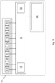
- a powertrain designated generally as 2, of an electric vehicle 4 is shown in plan view.
- the powertrain 2 comprises an energy storage means, in the form of a battery 5, operatively connected via an inverter 7 to an electric motor 6, which generates torque, and a drive transmission 8.
- the drive transmission 8 could take the form of a differential (no disconnection mechanism or gears).
- the torque is transferred through a driveline 10 to wheels 12 that generate a tractive force to move the vehicle 4.
- a controller 14 is operatively connected to the electric motor 6 by the inverter 7, and functions to control the generation of torque by converting an accelerator pedal position to a torque output using an accelerator pedal map.
- figure 1 only shows one motor 6 driving the wheels of a rear axle, it will apparent that the vehicle 4 may be arranged so that it has one motor driving the wheels of a front axle, or may have at least one additional motor to drive the wheels of both the front a and rear axles, or additional motors to drive individual wheels.
- Figure 2 shows a graph 28, in the form of an accelerator pedal map, relating the torque requested from the electric motor 6 to the travel of the accelerator pedal.
- a full map would consist of a torque surface in the Z (vertical) axis based on the accelerator pedal position in one axis and the motor speed or vehicle speed in another axis. The required torque is the output.
- Line 30 shows the road load plotted against the position of the accelerator pedal.
- the term "road load” refers to the torque that opposes the movement of the vehicle 4 or, in other words, the torque necessary for maintaining the speed of the vehicle 4.
- Line 30 shows that the torque increases with respect to the accelerator pedal position to a maximum torque output relating to the maximum torque deliverable by the powertrain 2 when the accelerator pedal is fully pressed (100%accelerator pedal position). Conversely, the torque output decreases with respect to pedal position to a minimum when the accelerator pedal is fully released (0% accelerator pedal position), which relates to the maximum resistive torque or overrun torque requested from the electric motor 6 by a powertrain control unit 26.
- the relationship between the road load and the accelerator pedal position can be characterised generally as being constantly proportional. However, such a relationship cannot deliver a driving experience comparable to what the driver would expect from driving a vehicle comprising an ICE. To this end, the controller 14 functions to provide an intuitive driving experience.
- the controller 14 is operable to receive input data regarding the operation of the vehicle 4 and to issue a torque request to the powertrain control unit 26 to achieve a control objective, such as an acceleration demand from the driver of the vehicle 4.
- the input data comprises a plurality of electrical signals relating to: the accelerator pedal position 17; the vehicle speed 18; the vehicle longitudinal inclination 20; a terrain response mode 22; the current torque 24 being delivered by the electric motor 6; the road load 25; optionally, the road load accelerator pedal position 27; the maximum torque 29 deliverable by the powertrain 2; the overrun torque 31 requested by the powertrain control unit 26; and, the state of charge 21 of the battery 5.
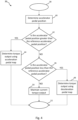
- the controller 14 incorporates software to implement the process 36 shown in the block diagram.
- the process 36 initiates at step 38, which may be when the vehicle 4 is operating under road load conditions.
- the current position of the accelerator pedal is determined.
- the position of the accelerator pedal is then compared, at step 42, against a reference accelerator pedal position to determine if it is greater than the reference accelerator pedal position.
- the reference accelerator pedal position relates to the road load accelerator pedal position 27. If it is determined that the accelerator pedal position is greater than the reference accelerator pedal position, the process 36 progresses to step 44 where a torque output is determined using an acceleration pedal 54 map before the process 36 terminates at step 52.
- step 46 it is determined if the accelerator pedal position equals or is less than the reference accelerator pedal position. If the accelerator pedal position equals the reference accelerator pedal position, the process 36 progresses to step 50 where the current torque output is maintained before the process 36 terminates at step 52. However, if it is determined, at step 46, that the accelerator pedal position is less than the reference accelerator pedal position, the process 36 progresses to step 48 where a torque output is determined using a deceleration pedal map 56 before the process 36 terminates at step 52. It is envisaged that the process 36 could repeat continually (e.g. at every execution cycle of a given software task).
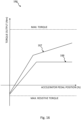
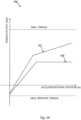
- Figure 5 shows a graph 58, in the form of an accelerator pedal map, illustrating the operation carried out by the process 36.
- the relationship between the road load and the accelerator pedal position is shown by line 30.
- the controller 14 is configured to receive a road load signal 25, indicative of the road load (to RL ), and determine a road load accelerator pedal position signal 27.
- the road load accelerator pedal position signal 27 is indicative of the reference accelerator pedal position (a ref ).
- the reference accelerator pedal position is the road load accelerator pedal position (a ref ), but for some implementations or circumstances, it may be desirable to determine the reference accelerator pedal position on the basis of other factors in addition to the road load accelerator pedal position.
- the controller 14 is further configured to receive an accelerator pedal position signal 17, which indicates the current accelerator pedal position, and compare the reference accelerator pedal position signal 27 and the accelerator pedal position signal 17 to determine the position of the accelerator pedal with respect to the reference accelerator pedal position (a ref ). If the accelerator pedal position is greater than the reference accelerator pedal position (a ref ), the controller 14 determines that an acceleration demand has been requested by the driver of the vehicle 4. In this case, a torque output is determined using an acceleration pedal map 60. On the other hand, if the accelerator pedal position is less than the reference accelerator pedal position (a ref ), the controller 14 decides that a deceleration demand has been requested and determines a torque output using a deceleration pedal map 62.
- the lower and upper limits of the acceleration pedal map 60 are set by the road load (to RL ) and the maximum torque deliverable by the powertrain 2, respectively.
- the lower and upper limits of the deceleration pedal map 62 are set by the maximum resistive torque and the road load (to RL ), respectively.
- the acceleration and deceleration pedal maps 60, 62 are customisable to provide an intuitive driving experience more akin to driving a vehicle comprising an ICE.
- the acceleration and deceleration pedal maps 60, 62 could be customised according to the speed of the vehicle 4.
- the acceleration pedal map 60 comprises a low-speed acceleration pedal map and a high-speed acceleration pedal map.
- the deceleration pedal map 62 comprises a low-speed deceleration pedal map and a high-speed deceleration pedal map.
- the controller 14 is configured to receive a vehicle speed signal 18, indicative of the speed of the vehicle 4, and determine a torque output in dependence on the vehicle speed signal 18. If the accelerator pedal position is greater than the reference accelerator pedal position (a ref ) and it is determined that the speed of the vehicle 4 is below a predetermined threshold speed the controller 14 determines a torque output using the low-speed acceleration pedal map.
- the controller 14 determines a torque output using the high-speed acceleration pedal map. Similarly, if the accelerator pedal position is less than the reference accelerator pedal position (a ref ) and the speed of the vehicle 4 is below the predetermined threshold speed, the controller 14 determines a torque output using the low-speed deceleration pedal map. Moreover, if the accelerator pedal position is less than the reference accelerator pedal position (a ref ) and the speed of the vehicle 4 is greater than the predetermined threshold speed, the controller 14 determines a torque output using the high-speed deceleration pedal map.
- selection of the low-speed and high-speed acceleration and deceleration pedal maps may be dependent on the vehicle speed relative to different speed limits. If the accelerator pedal position is greater than the reference accelerator pedal position (a ref ) and it is determined that the speed of the vehicle 4 equals or is below a predetermined low-speed limit, the controller 14 determines a torque output using the low-speed acceleration pedal map. However, if the accelerator pedal position is greater than the reference accelerator pedal position (a ref ) and the speed of the vehicle 4 equals or is greater than a predetermined high-speed limit, the controller 14 determines a torque output using the high-speed acceleration pedal map.
- the controller 14 determines a torque output using the low-speed deceleration pedal map. Moreover, if the accelerator pedal position is less than the reference accelerator pedal position (a ref ) and the speed of the vehicle 4 equals or is greater than a predetermined high-speed limit, the controller 14 determines a torque output using the high-speed deceleration pedal map.
- the controller 14 is further configured to determine a torque output based a combination of the low-speed and high-speed acceleration pedal maps if the accelerator pedal position is greater than the reference accelerator pedal position (a ref ), but the speed of the vehicle 4 is between the low-speed and high-speed limits. Likewise, a torque output is determined based a combination of the low-speed and high-speed deceleration pedal maps when the accelerator pedal position is less than the reference accelerator pedal position (a ref ), but the speed of the vehicle 4 is between the low-speed and high-speed limits. Combining pedal maps may be done by interpolating between the low-speed and high-speed pedal maps in dependence on the vehicle speed.
- the controller 14 may also be configured to modify the acceleration and deceleration pedal maps, or the low-speed and high-speed versions thereof, using a gradient modifier to take into account a gradient of the surface the vehicle 4 is traversing.
- the controller 14 determines the gradient modifier in dependence on the vehicle longitudinal inclination or gradient signal 20.
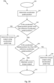
- the controller 14 incorporates software to implement the process 64 shown in the block diagram.
- the process 64 initiates at step 66 and progresses to step 68, where it is determined whether the vehicle 4 is traversing a gradient. This can be done using the vehicle longitudinal inclination or gradient signal 20. If it is determined that the vehicle 4 is traversing a gradient, the process 64 moves to step 70 where it is determined whether the gradient is a positive gradient or a negative gradient. If, at step 70, it is determined that the vehicle 4 is traversing a positive gradient, the process 64 moves to step 72 and a torque output is determined using a positive gradient pedal map.
- step 70 it is determined that the vehicle 4 is traversing a negative gradient
- the process 64 moves to step 74 and a torque output is determined using a negative gradient pedal map.
- steps 72, 74 the process 64 terminates at step 76. Basing the torque output on accelerator pedal maps that have been modified to account for the gradient of the surface the vehicle 4 is traversing prevents the perceived performance reduction that occurs in electric vehicles, which do not have a traditional gearbox, and offers the opportunity to enhance an electrified powertrain capability feel over a conventional one.
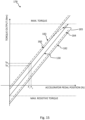
- Figure 7 shows a graph 78 illustrating the operation carried out by the process 64.
- the graph 78 comprises three accelerator pedal maps.
- Line 30 shows an accelerator pedal map under road load conditions, and lines 80, 82 are the positive gradient and the negative gradient accelerator pedal maps respectively. That is, lines 80, 82 are accelerator pedal maps that have been altered to account for a positive gradient and a negative gradient respectively.
- the degree to which lines 80, 82 are altered may also be influenced by the terrain response mode selected by the driver of the vehicle 4, in addition to gradient.
- the controller 14 is configured to determine the selected terrain response mode using the terrain response mode signal 22. It can be seen from line 80 that the torque output is greater, for the same accelerator pedal position, when compared to road load conditions. Conversely, line 82 shows that the torque output is less when compared to road load conditions for the same accelerator pedal position.
- the graph 78 comprises two additional accelerator pedal maps, lines 83, 84. These lines 83, 84 represent the torque output necessary for maintaining the speed of the vehicle 4 when going from road load conditions to traversing a positive gradient or a negative gradient respectively. Lines 83, 84 have been altered to account for the same gradients as lines 80, 82.
- the controller 14 functions to determine torque output using the positive gradient accelerator pedal map, line 80. It can be seen from comparing lines 80, 83 that, for the same accelerator pedal position (a 1 ), the torque output (to 1 ) from the positive gradient accelerator pedal map, line 80, is less than the torque (to 2 ) necessary for maintaining the speed of the vehicle 4 while traversing the positive gradient.
- Figure 15 shows a graph 178 illustrating the operation carried out by the process 164.
- the graph 178 comprises three accelerator pedal maps.
- Line 130 shows an accelerator pedal map under road load conditions
- lines 180, 182 are the positive gradient and the negative gradient accelerator pedal maps respectively. That is, lines 180, 182 are accelerator pedal maps that have been altered to account for a positive gradient and a negative gradient respectively.
- the degree to which lines 180, 182 are altered may also be influenced by the terrain response mode selected by the driver of the vehicle 104, in addition to gradient.
- the controller 114 is configured to determine the selected terrain response mode using the terrain response mode signal 122. It can be seen from line 180 that the torque output is greater, for the same accelerator pedal position, when compared to road load conditions. Conversely, line 182 shows that the torque output is less when compared to road load conditions for the same accelerator pedal position.
- the controller 214 is further configured to receive an accelerator pedal position signal 217, which indicates the current accelerator pedal position, and compare the reference accelerator pedal position signal 227 and the accelerator pedal position signal 217 to determine the position of the accelerator pedal with respect to the reference accelerator pedal position. If the accelerator pedal position is greater than the reference accelerator pedal position, the controller 214 determines that an acceleration demand has been requested by the driver of the vehicle 204. In this case, a torque output is determined using an acceleration pedal map 260. On the other hand, if the accelerator pedal position is less than the reference accelerator pedal position, the controller 214 decides that a deceleration demand has been requested and determines a torque output using a deceleration pedal map 262.
- the lower and upper limits of the acceleration pedal map 260 are set by the road load and the maximum torque deliverable by the powertrain 202, respectively.
- the lower and upper limits of the deceleration pedal map 262 are set by the maximum resistive torque and the road load, respectively.
- the acceleration and deceleration pedal maps 260, 262 are customisable to provide an intuitive driving experience more akin to driving a vehicle comprising an ICE.
- the acceleration and deceleration pedal maps 260, 262 could be customised according to the speed of the vehicle 204.
- the controller 214 determines a torque output using the high-speed acceleration pedal map. Similarly, if the accelerator pedal position is less than the reference accelerator pedal position and the speed of the vehicle 204 is below the predetermined threshold speed, the controller 214 determines a torque output using the low-speed deceleration pedal map. Moreover, if the accelerator pedal position is less than the reference accelerator pedal position and the speed of the vehicle 204 is greater than the predetermined threshold speed, the controller 214 determines a torque output using the high-speed deceleration pedal map.
- selection of the low-speed and high-speed acceleration and deceleration pedal maps may be dependent on the vehicle speed relative to different speed limits. If the accelerator pedal position is greater than the reference accelerator pedal position and it is determined that the speed of the vehicle 204 equals or is below a predetermined low-speed limit, the controller 214 determines a torque output using the low-speed acceleration pedal map. However, if the accelerator pedal position is greater than the reference accelerator pedal position and the speed of the vehicle 204 equals or is greater than a predetermined high-speed limit, the controller 214 determines a torque output using the high-speed acceleration pedal map.
- the controller 214 may also be configured to modify the acceleration and deceleration pedal maps, or the low-speed and high-speed versions thereof, using a gradient modifier to take into account a gradient of the surface the vehicle 204 is traversing.
- the controller 214 determines the gradient modifier in dependence on the vehicle longitudinal inclination or gradient signal 220.
- the controller may be configured to selectively inhibit or modify the application of acceleration or deceleration pedal maps in dependence on the surface over which the vehicle is travelling.
- the controller may be configured to selectively inhibit or modify the application of acceleration or deceleration pedal maps in dependence on a received or determined terrain mode, or a terrain type received from a further vehicle system or controller.
- controllers described herein may suitably comprise a control unit or computational device having one or more electronic processors.
- the system may comprise a single control unit or electronic controller or alternatively different functions of the controller may be embodied in, or hosted in, different control units or controllers.
- controller or “control unit” will be understood to include both a single control unit or controller and a plurality of control units or controllers collectively operating to provide any stated control functionality.
- a suitable set of instructions may be provided which, when executed, cause said control unit or computational device to implement the control techniques specified herein.
- the set of instructions may suitably be embedded in said one or more electronic processors.
- the set of instructions may be provided as software saved on one or more memory associated with said controller to be executed on said computational device.
- a first controller may be implemented in software run on one or more processors.
- One or more other controllers may be implemented in software run on one or more processors, optionally the same one or more processors as the first controller. Other suitable arrangements may also be used.
Landscapes
- Engineering & Computer Science (AREA)
- Automation & Control Theory (AREA)
- Transportation (AREA)
- Mechanical Engineering (AREA)
- Human Computer Interaction (AREA)
- Power Engineering (AREA)
- Mathematical Physics (AREA)
- Physics & Mathematics (AREA)
- Life Sciences & Earth Sciences (AREA)
- Sustainable Development (AREA)
- Sustainable Energy (AREA)
- Control Of Vehicle Engines Or Engines For Specific Uses (AREA)
- Electric Propulsion And Braking For Vehicles (AREA)
- Control Of Driving Devices And Active Controlling Of Vehicle (AREA)
Abstract
Description
- The present disclosure relates to a controller for a vehicle. Aspects of the invention relate to a controller, a control system, a vehicle and to a method.
- A conventional powertrain for a vehicle delivers a given amount of resistive torque due to the internal losses of an internal combustion engine (ICE) when the accelerator pedal is released. The level of restive torque or "overrun" provided by the ICE by can be increased by downshifting gears, which increases the frictional and pumping losses of the ICE. With electrification of the powertrain, it is now possible to offer a customisable level of resistive torque when the accelerator pedal is released by emulating the internal losses of an ICE to single-pedal driving. However, known emulations of these losses fail to reproduce accurately the experience that drivers expect from driving a vehicle comprising an ICE.
- The present invention has been devised to mitigate or overcome the above-mentioned problem.
- According to an aspect of the present invention there is provided a controller for a vehicle, the controller being configured to:
- determine the position of the accelerator pedal with respect to a reference accelerator pedal position; and,
- determine a torque output in dependence on an acceleration pedal map if the position of the accelerator pedal is greater than the reference accelerator pedal position; or,
- determine a torque output in dependence on a deceleration pedal map if the position of the accelerator pedal is less than the reference accelerator pedal position.
- The controller may be configured to:
- receive a road load signal indicative of a torque value suitable for maintaining the current speed of the vehicle;
- determine a road load accelerator pedal position signal in dependence on the road load signal, the road load accelerator pedal position signal being indicative of the reference accelerator pedal position;
- receive an accelerator pedal position signal indicative of the current position of the accelerator pedal; and,
- compare the reference accelerator pedal position signal and the accelerator pedal position signal to determine the position of the accelerator pedal with respect to the reference accelerator pedal position.
- The controller may be configured to:
- receive a maximum torque signal indicative of the maximum torque deliverable by the powertrain of the vehicle; and,
- determine the acceleration pedal map in dependence on the road load signal and the maximum torque signal.
- The controller may be configured to:
- receive an overrun torque demand signal indicative of the level of overrun torque requested by a vehicle system; and,
- determine the deceleration pedal map in dependence on the road load signal and the overrun toque demand signal.
- Optionally, the road load signal is a function of at least one of:
- the speed of the vehicle;
- the gradient of the surface the vehicle is traversing;
- the terrain response mode; and,
- the torque requested from the powertrain of the vehicle.
- Optionally, the maximum torque signal is a function of at least one of:
- the speed of the vehicle;
- the gradient of the surface the vehicle is traversing;
- the terrain response mode; and,
- the torque requested from the powertrain of the vehicle.
- Optionally, the overrun torque demand signal is a function of at least one of:
- the speed of the vehicle;
- the gradient of the surface the vehicle is traversing;
- the terrain response mode; and,
- the torque requested from the powertrain of the vehicle.
- In an embodiment, the acceleration pedal map comprises a low-speed acceleration pedal map and a high-speed acceleration pedal map.
- In an embodiment, the deceleration pedal map comprises a low-speed deceleration pedal map and a high-speed deceleration pedal map.
- The controller may be configured to:
- receive a vehicle speed signal indicative of the speed of the vehicle; and,
- determine a torque output according to the low-speed acceleration pedal map if the position of the accelerator pedal is greater than the reference accelerator pedal position and the vehicle speed equals or is less than a low-speed limit; or,
- determine a torque output according to the high-speed acceleration pedal map if the position of the accelerator pedal is greater than the reference accelerator pedal position and the vehicle speed equals or is greater than a high-speed limit.
- The controller may be configured to:
- receive a vehicle speed signal indicative of the speed of the vehicle; and,
- determine a torque output according to the low-speed deceleration pedal map if the position of the accelerator pedal is less than the reference accelerator pedal position and the vehicle speed equals or is less than a low-speed limit; or,
- determine a torque output according to the high-speed deceleration pedal map if the position of the accelerator pedal is less than the reference accelerator pedal position and the vehicle speed equals or is greater than a high-speed limit.
- The controller may be configured to determine a torque output in dependence on the low-speed acceleration pedal map and the high-speed acceleration pedal map if the position of the accelerator pedal is greater than the reference accelerator pedal position and the vehicle speed is between the low-speed limit and the high-speed limit.
- The controller may be configured to determine a torque output in dependence on the low-speed deceleration pedal map and the high-speed deceleration pedal map if the position of the accelerator pedal is less than the reference accelerator pedal position and the vehicle speed is between the low-speed limit and the high-speed limit.
- The controller may be configured to determine the torque output in dependence on the vehicle speed.
- According to a further aspect of the present invention there is provided a control system for an accelerator pedal of a vehicle, the control system comprising a controller according to the previous aspect.
- According to a further aspect of the present invention there is provided a vehicle comprising a control system according to the previous aspect.
- According to a further aspect of the present invention, the controller may be configured to selectively inhibit or modify the application of acceleration or deceleration pedal maps in dependence on the surface over which the vehicle is travelling.
- The controller may be configured to selectively inhibit or modify the application of acceleration or deceleration pedal maps in dependence on a received or determined terrain mode, or a terrain type received from a further vehicle system or controller.
- According to a further aspect of the invention is provided a method of controlling a vehicle, the method comprising: determining the position of the accelerator pedal with respect to a reference accelerator pedal position; and determining a torque output in dependence on an acceleration pedal map if the position of the accelerator pedal is greater than the reference accelerator pedal position; or determining a torque output in dependence on a deceleration pedal map if the position of the accelerator pedal is less than the reference accelerator pedal position.
- According to an aspect of the present invention there is provided a controller for a vehicle, the controller being configured to:
- receive a gradient signal indicative of the gradient of a surface the vehicle is traversing; and,
- determine a torque output in dependence on a positive gradient pedal map if the gradient signal indicates that the surface has a positive gradient; or
- determine a torque output in dependence on a negative gradient pedal map if the gradient signal indicates that the surface has a negative gradient.
- In an embodiment, the torque output from the positive gradient pedal map is less than the torque value required for maintaining the speed of the vehicle on the positive gradient for the same pedal position.
- In an embodiment, the torque output from the negative gradient map is less than the torque value required for maintaining the speed of the vehicle on the negative gradient for the same pedal position.
- The controller may be configured to:
- receive a maximum torque signal indicative of the maximum torque deliverable by the powertrain of the vehicle;
- receive an overrun torque signal indicative of the maximum overrun torque deliverable by a vehicle system; and,
- determine a road load pedal map in dependence on the maximum torque signal and the maximum overrun torque signal.
- The controller may be configured to determine the positive gradient pedal map in dependence on the road load pedal map and the gradient signal.
- The controller may be configured to determine the negative gradient pedal map in dependence on the road load pedal map and the gradient signal.
- In an embodiment, the positive gradient pedal map is offset from the road load pedal map such that the maximum torque output according to the positive gradient pedal map is greater than the maximum torque deliverable by the powertrain of the vehicle.
- In an embodiment, the negative gradient pedal map is offset from the road load pedal map such that the minimum torque output according to the negative gradient pedal map is less than maximum overrun torque deliverable by a vehicle system.
- The controller may be configured to determine a gradient modifier and modify the torque output in dependence on the gradient modifier.
- According to another aspect of the present invention there is provided a controller for a vehicle, the controller being configured to:
- receive a gradient signal indicative of the gradient of a surface the vehicle is traversing;
- determine a gradient modifier in dependence on the gradient signal;
- modify an acceleration pedal map and a deceleration pedal map in dependence on the gradient modifier;
- determine the position of the accelerator pedal with respect to a reference accelerator pedal position; and
- determine a torque output in dependence on the acceleration pedal map if the position of the accelerator pedal is greater than the reference accelerator pedal position; or,
- determine a torque output in dependence on the deceleration pedal map if the position of the accelerator pedal is less than the reference accelerator pedal position.
- In an embodiment, the acceleration map and the deceleration map are modified so as to reduce the torque output with respect to the position of the pedal.
- The controller may be configured to:
- receive a road load signal indicative of a torque value suitable for maintaining the current speed of the vehicle;
- receive a road load accelerator pedal position signal in dependence on the road load signal, the road load accelerator pedal position signal being indicative of the reference accelerator pedal position;
- receive an accelerator pedal position signal indicative of the current position of the accelerator pedal; and,
- compare the reference accelerator pedal position signal and the accelerator pedal position signal to determine the position of the accelerator pedal with respect to the reference accelerator pedal position.
- The controller may be configured to:
- receive a maximum torque signal indicative of the maximum torque deliverable by the powertrain of the vehicle; and,
- determine the acceleration pedal map in dependence on the road load signal and the maximum torque signal.
- The controller may be configured to:
- receive an overrun torque demand signal indicative of the level of overrun torque requested by a vehicle system; and,
- determine the deceleration pedal map in dependence on the road load signal and the overrun toque demand signal.
- Optionally, the road load signal is a function of at least one of:
- the speed of the vehicle;
- the gradient of the surface the vehicle is traversing;
- the terrain response mode; and,
- the torque requested from the powertrain of the vehicle.
- Optionally, the maximum torque signal is a function of at least one of:
- the speed of the vehicle;
- the gradient of the surface the vehicle is traversing;
- the terrain response mode; and,
- the torque requested from the powertrain of the vehicle.
- Optionally, the overrun torque demand signal is a function of at least one of:
- the speed of the vehicle;
- the gradient of the surface the vehicle is traversing;
- the terrain response mode; and,
- the torque requested from the powertrain of the vehicle.
- In an embodiment, the acceleration pedal map comprises a low-speed acceleration pedal map and a high-speed acceleration pedal map.
- In an embodiment, the deceleration pedal map comprises a low-speed deceleration pedal map and a high-speed deceleration pedal map.
- The controller may be configured to:
- receive a vehicle speed signal indicative of the speed of the vehicle; and,
- determine a torque output according to the low-speed acceleration pedal map if the position of the accelerator pedal is greater than the reference accelerator pedal position and the vehicle speed equals or is less than a low-speed limit; or,
- determine a torque output according to the high-speed acceleration pedal map if the position of the accelerator pedal is greater than the reference accelerator pedal position and the vehicle speed equals or is greater than a high-speed limit.
- The controller may be configured to:
- receive a vehicle speed signal indicative of the speed of the vehicle; and,
- determine a torque output according to the low-speed deceleration pedal map if the position of the accelerator pedal is less than the reference accelerator pedal position and the vehicle speed equals or is less than a low-speed limit; or,
- determine a torque output according to the high-speed deceleration pedal map if the position of the accelerator pedal is less than the reference accelerator pedal position and the vehicle speed equals or is greater than a high-speed limit.
- The controller may be configured to determine a torque output in dependence on the low-speed acceleration pedal map and the high-speed acceleration pedal map if the position of the accelerator pedal is greater than the reference accelerator pedal position and the vehicle speed is between the low-speed limit and the high-speed limit.
- The controller may be configured to determine a torque output in dependence on the low-speed deceleration pedal map and the high-speed deceleration pedal map if the position of the accelerator pedal is less than the reference accelerator pedal position and the vehicle speed is between the low-speed limit and the high-speed limit.
- The controller may be configured to determine the torque output in dependence on the vehicle speed.
- The controller may be configured to inhibit the positive gradient pedal map and / or the negative gradient pedal map in dependence on a terrain mode of the vehicle.
- In an embodiment, the terrain mode of the vehicle is a sand mode or a rock mode.
- According to a further aspect of the present invention there is provided a control system for a vehicle, the control system comprising a controller according to the previous aspect.
- According to a further aspect of the present invention there is provided a vehicle comprising a control system according to the previous aspect.
- According to a further aspect of the present invention, the controller may be configured to selectively inhibit or modify the application of acceleration or deceleration pedal maps in dependence on the surface over which the vehicle is travelling.
- The controller may be configured to selectively inhibit or modify the application of acceleration or deceleration pedal maps in dependence on a received or determined terrain mode, or a terrain type received from a further vehicle system or controller.
- According to a further aspect of the invention is provided a method of controlling a vehicle, the method comprising: determining the position of the accelerator pedal with respect to a reference accelerator pedal position; and determining a torque output in dependence on an acceleration pedal map if the position of the accelerator pedal is greater than the reference accelerator pedal position; or determining a torque output in dependence on a deceleration pedal map if the position of the accelerator pedal is less than the reference accelerator pedal position.
- According to a further aspect of the invention is provided a method of controlling a vehicle, the method comprising: receiving a gradient signal indicative of the gradient of a surface the vehicle is traversing; determining a gradient modifier in dependence on the gradient signal; modifying an acceleration pedal map and a deceleration pedal map in dependence on the gradient modifier; determining the position of the accelerator pedal with respect to a reference accelerator pedal position; and determining a torque output in dependence on the acceleration pedal map if the position of the accelerator pedal is greater than the reference accelerator pedal position; or determining a torque output in dependence on the deceleration pedal map if the position of the accelerator pedal is less than the reference accelerator pedal position.
- According to an aspect of the present invention there is provided a controller for a vehicle, the controller being configured to:
- receive a state of charge signal indicative of the state of charge of an energy storage means of the vehicle;
- receive an accelerator pedal position signal indicative of the position of the accelerator pedal within a pedal position range;
- determine an accelerator pedal map in dependence on the state of charge signal; and,
- determine a torque output in dependence on the accelerator pedal map and the accelerator pedal position signal.
- In an embodiment, the accelerator pedal map is configured such that the torque output increases with respect to the pedal position.
- In an embodiment, the accelerator pedal map is configured such that the torque output is a linear function of the pedal position.
- In an embodiment, the accelerator pedal map is configured such that the torque output increases at a higher rate with respect to the accelerator pedal position over a first part of the pedal position range than a second part of the pedal position range.
- The controller may be configured to receive a vehicle speed signal indicative of the speed of the vehicle and wherein the accelerator pedal map is configured such that the torque output increases at a higher rate with respect to the accelerator pedal position when the speed of the vehicle is less than a predetermined speed limit than when the speed of the vehicle equals or is greater than the predetermined speed limit.
- In an embodiment, the accelerator pedal map is configured such that the torque output increases at a higher rate with respect to the accelerator pedal position when the toque output value is less than a predetermined torque limit than when the torque output value equals or is greater than the predetermined torque limit.
- In an embodiment, the accelerator pedal map is configured such that the torque output is less than the torque value required for maintaining the speed of the vehicle.
- The controller may be configured to:
- receive a torque signal indicative of the current torque being delivered by the powertrain of the vehicle; and,
- determine the torque output value in dependence on the current torque.
- In an embodiment, the accelerator pedal map is configured such that maximum torque output according to the accelerator pedal map is less than the maximum torque deliverable by the powertrain of the vehicle.
- The controller may be configured to:
- receive a maximum torque signal indicative of the maximum torque deliverable by the powertrain of the vehicle; and,
- determine the accelerator pedal map in dependence on the maximum torque signal.
- In an embodiment, the state of charge signal indicates that the state of charge of the energy storage means of the vehicle is below a predetermined threshold.
- According to a further aspect of the present invention there is provided a control system for an accelerator pedal of a vehicle, the control system comprising a controller according to the previous aspect.
- According to a further aspect of the present invention there is provided a vehicle comprising a control system according to the previous aspect.
- According to a further aspect of the invention there is provided a method of controlling a vehicle, the method comprising: receiving a state of charge signal indicative of the state of charge of an energy storage means of the vehicle; receiving an accelerator pedal position signal indicative of the position of the accelerator pedal within a pedal position range; determining an accelerator pedal map in dependence on the state of charge signal; and, determining a torque output in dependence on the accelerator pedal map and the accelerator pedal position signal.
- Within the scope of this application it is expressly intended that the various aspects, embodiments, examples and alternatives set out in the preceding paragraphs, in the claims and/or in the following description and drawings, and in particular the individual features thereof, may be taken independently or in any combination. That is, all embodiments and/or features of any embodiment can be combined in any way and/or combination, unless such features are incompatible. The applicant reserves the right to change any originally filed claim or file any new claim accordingly, including the right to amend any originally filed claim to depend from and/or incorporate any feature of any other claim although not originally claimed in that manner.
- One or more embodiments of the invention will now be described, by way of example only, with reference to the accompanying drawings, in which:
-
Figure 1 shows a schematic representation of a powertrain for use with an embodiment of this invention; -
Figure 2 shows a graph illustrating the torque output produced in response to an accelerator pedal position at road load conditions; -
Figure 3 shows a schematic representation of a controller according to an embodiment of this invention; -
Figure 4 shows a block diagram summarizing an example of a control method designed according to an embodiment of this invention; -
Figure 5 shows a graph illustrating the torque output produced in response to an accelerator pedal position according to the control method ofFigure 4 ; -
Figure 6 shows a block diagram summarizing an example of a control method designed according to an embodiment of this invention; -
Figure 7 shows a graph illustrating the torque output produced in response to an accelerator pedal position according to the control method ofFigure 6 ; and, -
Figure 8 shows a graph illustrating the torque output produced in response to an accelerator pedal position according to a control method designed according to an embodiment of this invention. -
Figure 9 shows a schematic representation of a powertrain for use with an embodiment of this invention; -
Figure 10 shows a graph illustrating the torque output produced in response to an accelerator pedal position at road load conditions; -
Figure 11 shows a schematic representation of a controller according to an embodiment of this invention; -
Figure 12 shows a block diagram summarizing an example of a control method designed according to an embodiment of this invention; -
Figure 13 shows a graph illustrating the torque output produced in response to an accelerator pedal position according to the control method ofFigure 12 ; -
Figure 14 shows a block diagram summarizing an example of a control method designed according to an embodiment of this invention; -
Figure 15 shows a graph illustrating the torque output produced in response to an accelerator pedal position according to the control method ofFigure 14 ; and, -
Figure 16 shows a graph illustrating the torque output produced in response to an accelerator pedal position according to a control method designed according to an embodiment of this invention. -
Figure 17 shows a schematic representation of a powertrain for use with an embodiment of this invention; -
Figure 18 shows a graph illustrating the torque output produced in response to an accelerator pedal position at road load conditions; -
Figure 19 shows a schematic representation of a controller according to an embodiment of this invention; -
Figure 20 shows a block diagram summarizing an example of a control method designed according to an embodiment of this invention; -
Figure 21 shows a graph illustrating the torque output produced in response to an accelerator pedal position according to the control method ofFigure 4 ; -
Figure 22 shows a block diagram summarizing an example of a control method designed according to an embodiment of this invention; -
Figure 23 shows a graph illustrating the torque output produced in response to an accelerator pedal position according to the control method ofFigure 6 ; and, -
Figure 24 shows a graph illustrating the torque output produced in response to an accelerator pedal position according to a control method designed according to an embodiment of this invention. - With reference to
Figure 1 , a powertrain, designated generally as 2, of anelectric vehicle 4 is shown in plan view. Thepowertrain 2 comprises an energy storage means, in the form of abattery 5, operatively connected via an inverter 7 to anelectric motor 6, which generates torque, and adrive transmission 8. Thedrive transmission 8 could take the form of a differential (no disconnection mechanism or gears). The torque is transferred through adriveline 10 towheels 12 that generate a tractive force to move thevehicle 4. Acontroller 14 is operatively connected to theelectric motor 6 by the inverter 7, and functions to control the generation of torque by converting an accelerator pedal position to a torque output using an accelerator pedal map. Althoughfigure 1 only shows onemotor 6 driving the wheels of a rear axle, it will apparent that thevehicle 4 may be arranged so that it has one motor driving the wheels of a front axle, or may have at least one additional motor to drive the wheels of both the front a and rear axles, or additional motors to drive individual wheels. -
Figure 2 shows agraph 28, in the form of an accelerator pedal map, relating the torque requested from theelectric motor 6 to the travel of the accelerator pedal. The skilled reader will understand that this is a simplified section through a map that may also incorporates vehicle speed or actuator speed. A full map would consist of a torque surface in the Z (vertical) axis based on the accelerator pedal position in one axis and the motor speed or vehicle speed in another axis. The required torque is the output.Line 30 shows the road load plotted against the position of the accelerator pedal. For clarity, the term "road load" refers to the torque that opposes the movement of thevehicle 4 or, in other words, the torque necessary for maintaining the speed of thevehicle 4.Line 30 shows that the torque increases with respect to the accelerator pedal position to a maximum torque output relating to the maximum torque deliverable by thepowertrain 2 when the accelerator pedal is fully pressed (100%accelerator pedal position). Conversely, the torque output decreases with respect to pedal position to a minimum when the accelerator pedal is fully released (0% accelerator pedal position), which relates to the maximum resistive torque or overrun torque requested from theelectric motor 6 by apowertrain control unit 26. The relationship between the road load and the accelerator pedal position can be characterised generally as being constantly proportional. However, such a relationship cannot deliver a driving experience comparable to what the driver would expect from driving a vehicle comprising an ICE. To this end, thecontroller 14 functions to provide an intuitive driving experience. - With reference to
Figure 3 , in accordance with embodiments of the invention, thecontroller 14 is operable to receive input data regarding the operation of thevehicle 4 and to issue a torque request to thepowertrain control unit 26 to achieve a control objective, such as an acceleration demand from the driver of thevehicle 4. The input data comprises a plurality of electrical signals relating to: theaccelerator pedal position 17; thevehicle speed 18; the vehiclelongitudinal inclination 20; aterrain response mode 22; thecurrent torque 24 being delivered by theelectric motor 6; theroad load 25; optionally, the road loadaccelerator pedal position 27; themaximum torque 29 deliverable by thepowertrain 2; theoverrun torque 31 requested by thepowertrain control unit 26; and, the state ofcharge 21 of thebattery 5. In this instance, the vehiclelongitudinal inclination 20 relates to the gradient of the surface thevehicle 4 is traversing. These electrical signals, together with thecontroller 14 and thepowertrain control unit 26 form part of acontrol system 35. Thecontroller 14 comprises aprocessor 32 configured to convert an accelerator pedal position to a torque output based on one or more accelerator pedal maps, which can be stored in and read from amemory module 34. Alternatively, the controller may be configured to determine the one or more accelerator pedal maps. The skilled reader will appreciate thatFigure 3 is provided only to illustrate an example of acontroller 14 architecture in which the invention may be implemented. - With reference to
Figure 4 , in accordance with an embodiment of the invention, thecontroller 14 incorporates software to implement theprocess 36 shown in the block diagram. Theprocess 36 initiates atstep 38, which may be when thevehicle 4 is operating under road load conditions. Atstep 40, the current position of the accelerator pedal is determined. The position of the accelerator pedal is then compared, atstep 42, against a reference accelerator pedal position to determine if it is greater than the reference accelerator pedal position. The reference accelerator pedal position relates to the road loadaccelerator pedal position 27. If it is determined that the accelerator pedal position is greater than the reference accelerator pedal position, theprocess 36 progresses to step 44 where a torque output is determined using an acceleration pedal 54 map before theprocess 36 terminates atstep 52. However, if atstep 42 it is determined that the accelerator pedal position is not greater than the reference accelerator pedal position, theprocess 36 progresses to step 46 where it is determined if the accelerator pedal position equals or is less than the reference accelerator pedal position. If the accelerator pedal position equals the reference accelerator pedal position, theprocess 36 progresses to step 50 where the current torque output is maintained before theprocess 36 terminates atstep 52. However, if it is determined, atstep 46, that the accelerator pedal position is less than the reference accelerator pedal position, theprocess 36 progresses to step 48 where a torque output is determined using a deceleration pedal map 56 before theprocess 36 terminates atstep 52. It is envisaged that theprocess 36 could repeat continually (e.g. at every execution cycle of a given software task). -
Figure 5 shows agraph 58, in the form of an accelerator pedal map, illustrating the operation carried out by theprocess 36. The relationship between the road load and the accelerator pedal position is shown byline 30. Thecontroller 14 is configured to receive aroad load signal 25, indicative of the road load (toRL), and determine a road load acceleratorpedal position signal 27. The road load acceleratorpedal position signal 27 is indicative of the reference accelerator pedal position (aref). In this example, the reference accelerator pedal position is the road load accelerator pedal position (aref), but for some implementations or circumstances, it may be desirable to determine the reference accelerator pedal position on the basis of other factors in addition to the road load accelerator pedal position. Thecontroller 14 is further configured to receive an acceleratorpedal position signal 17, which indicates the current accelerator pedal position, and compare the reference acceleratorpedal position signal 27 and the acceleratorpedal position signal 17 to determine the position of the accelerator pedal with respect to the reference accelerator pedal position (aref). If the accelerator pedal position is greater than the reference accelerator pedal position (aref), thecontroller 14 determines that an acceleration demand has been requested by the driver of thevehicle 4. In this case, a torque output is determined using anacceleration pedal map 60. On the other hand, if the accelerator pedal position is less than the reference accelerator pedal position (aref), thecontroller 14 decides that a deceleration demand has been requested and determines a torque output using adeceleration pedal map 62. The lower and upper limits of theacceleration pedal map 60 are set by the road load (toRL) and the maximum torque deliverable by thepowertrain 2, respectively. Whereas, the lower and upper limits of thedeceleration pedal map 62 are set by the maximum resistive torque and the road load (toRL), respectively. The acceleration and deceleration pedal maps 60, 62 are customisable to provide an intuitive driving experience more akin to driving a vehicle comprising an ICE. For example, the acceleration and deceleration pedal maps 60, 62 could be customised according to the speed of thevehicle 4. - In an embodiment of the invention, the
acceleration pedal map 60 comprises a low-speed acceleration pedal map and a high-speed acceleration pedal map. Similarly, thedeceleration pedal map 62 comprises a low-speed deceleration pedal map and a high-speed deceleration pedal map. Thecontroller 14 is configured to receive avehicle speed signal 18, indicative of the speed of thevehicle 4, and determine a torque output in dependence on thevehicle speed signal 18. If the accelerator pedal position is greater than the reference accelerator pedal position (aref) and it is determined that the speed of thevehicle 4 is below a predetermined threshold speed thecontroller 14 determines a torque output using the low-speed acceleration pedal map. However, if the accelerator pedal position is greater than the reference accelerator pedal position (aref) and the speed of thevehicle 4 is greater than the predetermined threshold speed, thecontroller 14 determines a torque output using the high-speed acceleration pedal map. Similarly, if the accelerator pedal position is less than the reference accelerator pedal position (aref) and the speed of thevehicle 4 is below the predetermined threshold speed, thecontroller 14 determines a torque output using the low-speed deceleration pedal map. Moreover, if the accelerator pedal position is less than the reference accelerator pedal position (aref) and the speed of thevehicle 4 is greater than the predetermined threshold speed, thecontroller 14 determines a torque output using the high-speed deceleration pedal map. - Alternatively, selection of the low-speed and high-speed acceleration and deceleration pedal maps may be dependent on the vehicle speed relative to different speed limits. If the accelerator pedal position is greater than the reference accelerator pedal position (aref) and it is determined that the speed of the
vehicle 4 equals or is below a predetermined low-speed limit, thecontroller 14 determines a torque output using the low-speed acceleration pedal map. However, if the accelerator pedal position is greater than the reference accelerator pedal position (aref) and the speed of thevehicle 4 equals or is greater than a predetermined high-speed limit, thecontroller 14 determines a torque output using the high-speed acceleration pedal map. Similarly, if the accelerator pedal position is less than the reference accelerator pedal position (aref) and the speed of thevehicle 4 equals or is below a predetermined low-speed limit, thecontroller 14 determines a torque output using the low-speed deceleration pedal map. Moreover, if the accelerator pedal position is less than the reference accelerator pedal position (aref) and the speed of thevehicle 4 equals or is greater than a predetermined high-speed limit, thecontroller 14 determines a torque output using the high-speed deceleration pedal map. Thecontroller 14 is further configured to determine a torque output based a combination of the low-speed and high-speed acceleration pedal maps if the accelerator pedal position is greater than the reference accelerator pedal position (aref), but the speed of thevehicle 4 is between the low-speed and high-speed limits. Likewise, a torque output is determined based a combination of the low-speed and high-speed deceleration pedal maps when the accelerator pedal position is less than the reference accelerator pedal position (aref), but the speed of thevehicle 4 is between the low-speed and high-speed limits. Combining pedal maps may be done by interpolating between the low-speed and high-speed pedal maps in dependence on the vehicle speed. - In a further embodiment of the invention, the
controller 14 may also be configured to modify the acceleration and deceleration pedal maps, or the low-speed and high-speed versions thereof, using a gradient modifier to take into account a gradient of the surface thevehicle 4 is traversing. Thecontroller 14 determines the gradient modifier in dependence on the vehicle longitudinal inclination orgradient signal 20. - With reference to
Figure 6 , in accordance with an embodiment of the invention, thecontroller 14 incorporates software to implement theprocess 64 shown in the block diagram. Theprocess 64 initiates atstep 66 and progresses to step 68, where it is determined whether thevehicle 4 is traversing a gradient. This can be done using the vehicle longitudinal inclination orgradient signal 20. If it is determined that thevehicle 4 is traversing a gradient, theprocess 64 moves to step 70 where it is determined whether the gradient is a positive gradient or a negative gradient. If, atstep 70, it is determined that thevehicle 4 is traversing a positive gradient, theprocess 64 moves to step 72 and a torque output is determined using a positive gradient pedal map. However, if, atstep 70, it is determined that thevehicle 4 is traversing a negative gradient, theprocess 64 moves to step 74 and a torque output is determined using a negative gradient pedal map. Followingsteps process 64 terminates atstep 76. Basing the torque output on accelerator pedal maps that have been modified to account for the gradient of the surface thevehicle 4 is traversing prevents the perceived performance reduction that occurs in electric vehicles, which do not have a traditional gearbox, and offers the opportunity to enhance an electrified powertrain capability feel over a conventional one. -
Figure 7 shows agraph 78 illustrating the operation carried out by theprocess 64. Thegraph 78 comprises three accelerator pedal maps.Line 30 shows an accelerator pedal map under road load conditions, andlines vehicle 4, in addition to gradient. Thecontroller 14 is configured to determine the selected terrain response mode using the terrainresponse mode signal 22. It can be seen fromline 80 that the torque output is greater, for the same accelerator pedal position, when compared to road load conditions. Conversely,line 82 shows that the torque output is less when compared to road load conditions for the same accelerator pedal position. - The
graph 78 comprises two additional accelerator pedal maps,lines lines vehicle 4 when going from road load conditions to traversing a positive gradient or a negative gradient respectively.Lines lines vehicle 4 is traversing a positive gradient, thecontroller 14 functions to determine torque output using the positive gradient accelerator pedal map,line 80. It can be seen from comparinglines line 80, is less than the torque (to2) necessary for maintaining the speed of thevehicle 4 while traversing the positive gradient. That is, the positive gradient accelerator pedal map,line 80, used by thecontroller 14 purposively under compensates for the positive gradient. In order to maintain the speed of thevehicle 4, the driver of thevehicle 4 is required to press the accelerator pedal to position (a2) to achieve the required torque output (to2). This situation is constructed by thecontroller 14 in order to provide an intuitive driving experience in which the driver would expect to have to press the accelerator pedal to some extent when traversing a positive gradient based on their experience of driving a vehicle comprising an ICE. - Similarly, the driver would expect to have to lift-off or release the accelerator pedal when going downhill. In view of that, the negative gradient accelerator pedal map,
line 82, used by thecontroller 14 purposively over compensates for the negative gradient, and so the driver of thevehicle 4 is required to release the accelerator pedal in order to maintain the speed of thevehicle 4 when traversing a negative gradient. - It can be seen that the upper limit of the positive gradient accelerator pedal map,
line 80, is offset from the road load accelerator pedal map,line 30, such that it exceeds the maximum torque deliverable by thepowertrain 2. This is done in order to prevent the effect of the gradient modification from dissipating, as indicated byline 85, as the torque demand increases away from the road load and towards the maximum torque deliverable by thepowertrain 2, which would be counter-intuitive for the driver of thevehicle 4. - In a further embodiment of the invention, the
controller 14 may determine an accelerator pedal map on receiving the state ofcharge signal 21, which indicates that the state of charge of thebattery 5 is below a predetermined threshold, and determine a torque output in dependence on the accelerator pedal map. -
Figure 8 shows agraph 86 including anaccelerator pedal map 87 in accordance with this embodiment of the invention. Thegraph 86 includes an additionalaccelerator pedal map 88. The additionalaccelerator pedal map 88 is an example of how known accelerator pedal maps are modified when the state of charge of an energy storage means on an electric vehicle falls below a threshold. In this example, it can be seen that theaccelerator pedal map 88 initially increases with the accelerator pedal position, after which a torque limit is applied and the torque output remains constant as the accelerator pedal position increases. However, rather than applying a torque limit, theaccelerator pedal map 87 is configured to deliver increasing amounts of torque with respect to pedal position up to a maximum which is less that the maximum torque deliverable by thepowertrain 2. Although this results in an overall lower output torque, the behaviour of thevehicle 4 is made to be more intuitive for the driver when compared to simply applying a torque limit. In embodiments of the invention, theaccelerator pedal map 87 is configured to maximise the range of thevehicle 4, increasing the likelihood of thevehicle 4 reaching its destination. Moreover, theaccelerator pedal map 87 could be configured so that the torque delivered over the first part of the accelerator pedal range is delivered at a higher rate when compared to the torque delivered over the second part of the accelerator pedal range. This means that the driver is able to accelerate in city traffic conditions and maintain a high cruising speed, but thevehicle 4 will have a lower acceleration in the second part of the accelerator pedal range. - The controller may be configured to selectively inhibit or modify the application of acceleration or deceleration pedal maps in dependence on the surface over which the vehicle is travelling.
- The controller may be configured to selectively inhibit or modify the application of acceleration or deceleration pedal maps in dependence on a received or determined terrain mode, or a terrain type received from a further vehicle system or controller.
- Any controller or controllers described herein may suitably comprise a control unit or computational device having one or more electronic processors. Thus the system may comprise a single control unit or electronic controller or alternatively different functions of the controller may be embodied in, or hosted in, different control units or controllers. As used herein the term "controller" or "control unit" will be understood to include both a single control unit or controller and a plurality of control units or controllers collectively operating to provide any stated control functionality. To configure a controller, a suitable set of instructions may be provided which, when executed, cause said control unit or computational device to implement the control techniques specified herein. The set of instructions may suitably be embedded in said one or more electronic processors. Alternatively, the set of instructions may be provided as software saved on one or more memory associated with said controller to be executed on said computational device. A first controller may be implemented in software run on one or more processors. One or more other controllers may be implemented in software run on one or more processors, optionally the same one or more processors as the first controller. Other suitable arrangements may also be used.
- With reference to
Figure 9 , a powertrain, designated generally as 102, of anelectric vehicle 104 is shown in plan view. Thepowertrain 102 comprises an energy storage means, in the form of abattery 105, operatively connected via aninverter 107 to anelectric motor 106, which generates torque, and adrive transmission 108. Thedrive transmission 108 could take the form of a differential (no disconnection mechanism or gears). The torque is transferred through adriveline 110 towheels 112 that generate a tractive force to move thevehicle 104. Acontroller 114 is operatively connected to theelectric motor 106 by theinverter 107, and functions to control the generation of torque by converting an accelerator pedal position to a torque output using an accelerator pedal map. Althoughfigure 9 only shows onemotor 106 driving the wheels of a rear axle, it will apparent that thevehicle 104 may be arranged so that it has one motor driving the wheels of a front axle, or may have at least one additional motor to drive the wheels of both the front a and rear axles, or additional motors to drive individual wheels. -
Figure 10 shows agraph 128, in the form of an accelerator pedal map, relating the torque requested from theelectric motor 106 to the travel of the accelerator pedal. The skilled reader will understand that this is a simplified section through a map that may also incorporates vehicle speed or actuator speed. A full map would consist of a torque surface in the Z (vertical) axis based on the accelerator pedal position in one axis and the motor speed or vehicle speed in another axis. The required torque is the output.Line 130 shows the road load plotted against the position of the accelerator pedal. For clarity, the term "road load" refers to the torque that opposes the movement of thevehicle 104 or, in other words, the torque necessary for maintaining the speed of thevehicle 104.Line 130 shows that the torque increases with respect to the accelerator pedal position to a maximum torque output relating to the maximum torque deliverable by thepowertrain 102 when the accelerator pedal is fully pressed (100% accelerator pedal position). Conversely, the torque output decreases with respect to pedal position to a minimum when the accelerator pedal is fully released (0% accelerator pedal position), which relates to the maximum resistive torque or overrun torque requested from theelectric motor 106 by apowertrain control unit 126. The relationship between the road load and the accelerator pedal position can be characterised generally as being constantly proportional. However, such a relationship cannot deliver a driving experience comparable to what the driver would expect from driving a vehicle comprising an ICE. To this end, thecontroller 114 functions to provide an intuitive driving experience. - With reference to
Figure 11 , in accordance with embodiments of the invention, thecontroller 114 is operable to receive input data regarding the operation of thevehicle 104 and to issue a torque request to thepowertrain control unit 126 to achieve a control objective, such as an acceleration demand from the driver of thevehicle 104. The input data comprises a plurality of electrical signals relating to: theaccelerator pedal position 117; thevehicle speed 118; the vehiclelongitudinal inclination 120; aterrain response mode 122; thecurrent torque 124 being delivered by theelectric motor 106; theroad load 125; optionally, the road loadaccelerator pedal position 127; themaximum torque 129 deliverable by thepowertrain 102; theoverrun torque 131 requested by thepowertrain control unit 126; and, the state of charge121 of thebattery 105. In this instance, the vehiclelongitudinal inclination 120 relates to the gradient of the surface thevehicle 104 is traversing. These electrical signals, together with thecontroller 114 and thepowertrain control unit 126 form part of acontrol system 135. Thecontroller 114 comprises aprocessor 132 configured to convert an accelerator pedal position to a torque output based on one or more accelerator pedal maps, which can be stored in and read from amemory module 134. Alternatively, the controller may be configured to determine the one or more accelerator pedal maps. The skilled reader will appreciate that Figure 103 is provided only to illustrate an example of acontroller 114 architecture in which the invention may be implemented. - With reference to
Figure 12 , in accordance with an embodiment of the invention, thecontroller 114 incorporates software to implement theprocess 136 shown in the block diagram. Theprocess 136 initiates atstep 138, which may be when thevehicle 104 is operating under road load conditions. Atstep 140, the current position of the accelerator pedal is determined. The position of the accelerator pedal is then compared, atstep 142, against a reference accelerator pedal position to determine if it is greater than the reference accelerator pedal position. The reference accelerator pedal position relates to the road loadaccelerator pedal position 127. If it is determined that the accelerator pedal position is greater than the reference accelerator pedal position, theprocess 136 progresses to step 144 where a torque output is determined using an acceleration pedal 154 map before theprocess 136 terminates atstep 152. However, if atstep 142 it is determined that the accelerator pedal position is not greater than the reference accelerator pedal position, theprocess 136 progresses to step 146 where it is determined if the accelerator pedal position equals or is less than the reference accelerator pedal position. If the accelerator pedal position equals the reference accelerator pedal position, theprocess 136 progresses to step 150 where the current torque output is maintained before theprocess 136 terminates atstep 152. However, if it is determined, atstep 146, that the accelerator pedal position is less than the reference accelerator pedal position, theprocess 136 progresses to step 148 where a torque output is determined using a deceleration pedal map 156 before theprocess 136 terminates atstep 152. It is envisaged that theprocess 136 could repeat continually (e.g. at every execution cycle of a given software task). -
Figure 13 shows agraph 158, in the form of an accelerator pedal map, illustrating the operation carried out by theprocess 136. The relationship between the road load and the accelerator pedal position is shown byline 130. Thecontroller 114 is configured to receive aroad load signal 125, indicative of the road load (toRL), and determine a road load acceleratorpedal position signal 127. The road load acceleratorpedal position signal 127 is indicative of the reference accelerator pedal position (aref). In this example, the reference accelerator pedal position is the road load accelerator pedal position (aref), but for some implementations or circumstances, it may be desirable to determine the reference accelerator pedal position on the basis of other factors in addition to the road load accelerator pedal position. Thecontroller 114 is further configured to receive an acceleratorpedal position signal 117, which indicates the current accelerator pedal position, and compare the reference accelerator pedal position signal 127 and the accelerator pedal position signal 117 to determine the position of the accelerator pedal with respect to the reference accelerator pedal position (aref). If the accelerator pedal position is greater than the reference accelerator pedal position (aref), thecontroller 114 determines that an acceleration demand has been requested by the driver of thevehicle 104. In this case, a torque output is determined using anacceleration pedal map 160. On the other hand, if the accelerator pedal position is less than the reference accelerator pedal position (aref), thecontroller 114 decides that a deceleration demand has been requested and determines a torque output using adeceleration pedal map 162. The lower and upper limits of theacceleration pedal map 160 are set by the road load (toRL) and the maximum torque deliverable by thepowertrain 102, respectively. Whereas, the lower and upper limits of thedeceleration pedal map 162 are set by the maximum resistive torque and the road load (toRL), respectively. The acceleration and deceleration pedal maps 160,162 are customisable to provide an intuitive driving experience more akin to driving a vehicle comprising an ICE. For example, the acceleration and deceleration pedal maps 160, 162 could be customised according to the speed of thevehicle 104. - In an embodiment of the invention, the
acceleration pedal map 160 comprises a low-speed acceleration pedal map and a high-speed acceleration pedal map. Similarly, thedeceleration pedal map 162 comprises a low-speed deceleration pedal map and a high-speed deceleration pedal map. Thecontroller 114 is configured to receive avehicle speed signal 118, indicative of the speed of thevehicle 104, and determine a torque output in dependence on thevehicle speed signal 118. If the accelerator pedal position is greater than the reference accelerator pedal position (aref) and it is determined that the speed of thevehicle 104 is below a predetermined threshold speed thecontroller 114 determines a torque output using the low-speed acceleration pedal map. However, if the accelerator pedal position is greater than the reference accelerator pedal position (aref) and the speed of thevehicle 104 is greater than the predetermined threshold speed, thecontroller 114 determines a torque output using the high-speed acceleration pedal map. Similarly, if the accelerator pedal position is less than the reference accelerator pedal position (aref) and the speed of thevehicle 104 is below the predetermined threshold speed, thecontroller 114 determines a torque output using the low-speed deceleration pedal map. Moreover, if the accelerator pedal position is less than the reference accelerator pedal position (aref) and the speed of thevehicle 104 is greater than the predetermined threshold speed, thecontroller 114 determines a torque output using the high-speed deceleration pedal map. - Alternatively, selection of the low-speed and high-speed acceleration and deceleration pedal maps may be dependent on the vehicle speed relative to different speed limits. If the accelerator pedal position is greater than the reference accelerator pedal position (aref) and it is determined that the speed of the
vehicle 104 equals or is below a predetermined low-speed limit, thecontroller 114 determines a torque output using the low-speed acceleration pedal map. However, if the accelerator pedal position is greater than the reference accelerator pedal position (aref) and the speed of thevehicle 104 equals or is greater than a predetermined high-speed limit, thecontroller 114 determines a torque output using the high-speed acceleration pedal map. Similarly, if the accelerator pedal position is less than the reference accelerator pedal position (aref) and the speed of thevehicle 104 equals or is below a predetermined low-speed limit, thecontroller 114 determines a torque output using the low-speed deceleration pedal map. Moreover, if the accelerator pedal position is less than the reference accelerator pedal position (aref) and the speed of thevehicle 104 equals or is greater than a predetermined high-speed limit, thecontroller 114 determines a torque output using the high-speed deceleration pedal map. Thecontroller 114 is further configured to determine a torque output based a combination of the low-speed and high-speed acceleration pedal maps if the accelerator pedal position is greater than the reference accelerator pedal position (aref), but the speed of thevehicle 104 is between the low-speed and high-speed limits. Likewise, a torque output is determined based a combination of the low-speed and high-speed deceleration pedal maps when the accelerator pedal position is less than the reference accelerator pedal position (aref), but the speed of thevehicle 104 is between the low-speed and high-speed limits. Combining pedal maps may be done by interpolating between the low-speed and high-speed pedal maps in dependence on the vehicle speed. - In a further embodiment of the invention, the
controller 114 may also be configured to modify the acceleration and deceleration pedal maps, or the low-speed and high-speed versions thereof, using a gradient modifier to take into account a gradient of the surface thevehicle 104 is traversing. Thecontroller 114 determines the gradient modifier in dependence on the vehicle longitudinal inclination orgradient signal 120. - With reference to
Figure 14 , in accordance with an embodiment of the invention, thecontroller 114 incorporates software to implement theprocess 164 shown in the block diagram. Theprocess 164 initiates atstep 166 and progresses to step 168, where it is determined whether thevehicle 104 is traversing a gradient. This can be done using the vehicle longitudinal inclination orgradient signal 120. If it is determined that thevehicle 104 is traversing a gradient, theprocess 164 moves to step 170 where it is determined whether the gradient is a positive gradient or a negative gradient. If, atstep 170, it is determined that thevehicle 104 is traversing a positive gradient, theprocess 164 moves to step 172 and a torque output is determined using a positive gradient pedal map. However, if, atstep 170, it is determined that thevehicle 104 is traversing a negative gradient, theprocess 164 moves to step 174 and a torque output is determined using a negative gradient pedal map. Followingsteps process 164 terminates atstep 176. Basing the torque output on accelerator pedal maps that have been modified to account for the gradient of the surface thevehicle 104 is traversing prevents the perceived performance reduction that occurs in electric vehicles, which do not have a traditional gearbox, and offers the opportunity to enhance an electrified powertrain capability feel over a conventional one. -
Figure 15 shows agraph 178 illustrating the operation carried out by theprocess 164. Thegraph 178 comprises three accelerator pedal maps.Line 130 shows an accelerator pedal map under road load conditions, andlines lines lines vehicle 104, in addition to gradient. Thecontroller 114 is configured to determine the selected terrain response mode using the terrainresponse mode signal 122. It can be seen fromline 180 that the torque output is greater, for the same accelerator pedal position, when compared to road load conditions. Conversely,line 182 shows that the torque output is less when compared to road load conditions for the same accelerator pedal position. - The
graph 178 comprises two additional accelerator pedal maps, lines 183,184. Theselines vehicle 104 when going from road load conditions to traversing a positive gradient or a negative gradient respectively.Lines lines vehicle 104 is traversing a positive gradient, thecontroller 114 functions to determine torque output using the positive gradient accelerator pedal map,line 180. It can be seen from comparinglines line 180, is less than the torque (to2) necessary for maintaining the speed of thevehicle 4 while traversing the positive gradient. That is, the positive gradient accelerator pedal map,line 180, used by thecontroller 114 purposively under compensates for the positive gradient. In order to maintain the speed of thevehicle 104, the driver of thevehicle 104 is required to press the accelerator pedal to position (a2) to achieve the required torque output (to2). This situation is constructed by thecontroller 114 in order to provide an intuitive driving experience in which the driver would expect to have to press the accelerator pedal to some extent when traversing a positive gradient based on their experience of driving a vehicle comprising an ICE. - Similarly, the driver would expect to have to lift-off or release the accelerator pedal when going downhill. In view of that, the negative gradient accelerator pedal map,
line 182, used by thecontroller 114 purposively over compensates for the negative gradient, and so the driver of thevehicle 104 is required to release the accelerator pedal in order to maintain the speed of thevehicle 4 when traversing a negative gradient. - It can be seen that the upper limit of the positive gradient accelerator pedal map,
line 180, is offset from the road load accelerator pedal map,line 130, such that it exceeds the maximum torque deliverable by thepowertrain 102. This is done in order to prevent the effect of the gradient modification from dissipating, as indicated byline 185, as the torque demand increases away from the road load and towards the maximum torque deliverable by thepowertrain 102, which would be counter-intuitive for the driver of thevehicle 104. - In some circumstances, particularly in off-highway or off-road terrain, it may be undesirable to modify the pedal response in this way, for example when traversing some terrain types where consistent control of the vehicle torque irrespective of the gradient is desirable. The controller may be configured to inhibit the positive gradient pedal map and / or the negative gradient pedal map in dependence on a terrain mode of the vehicle. The terrain mode may be selected by a driver of the vehicle, or determined automatically by a control system of the vehicle. For example, the controller may be configured to inhibit the positive gradient pedal map and / or the negative gradient pedal map the terrain mode of the vehicle is a sand mode or a rock mode.
- In a further embodiment of the invention, the
controller 114 may determine an accelerator pedal map on receiving the state ofcharge signal 121, which indicates that the state of charge of thebattery 105 is below a predetermined threshold, and determine a torque output in dependence on the accelerator pedal map. -
Figure 16 shows agraph 186 including anaccelerator pedal map 187 in accordance with this embodiment of the invention. Thegraph 186 includes an additionalaccelerator pedal map 188. The additionalaccelerator pedal map 188 is an example of how known accelerator pedal maps are modified when the state of charge of an energy storage means on an electric vehicle falls below a threshold. In this example, it can be seen that theaccelerator pedal map 188 initially increases with the accelerator pedal position, after which a torque limit is applied and the torque output remains constant as the accelerator pedal position increases. However, rather than applying a torque limit, theaccelerator pedal map 187 is configured to deliver increasing amounts of torque with respect to pedal position up to a maximum which is less that the maximum torque deliverable by thepowertrain 102. Although this results in an overall lower output torque, the behaviour of thevehicle 104 is made to be more intuitive for the driver when compared to simply applying a torque limit. In embodiments of the invention, theaccelerator pedal map 187 is configured to maximise the range of thevehicle 104, increasing the likelihood of thevehicle 104 reaching its destination. Moreover, theaccelerator pedal map 187 could be configured so that the torque delivered over the first part of the accelerator pedal range is delivered at a higher rate when compared to the torque delivered over the second part of the accelerator pedal range. This means that the driver is able to accelerate in city traffic conditions and maintain a high cruising speed, but thevehicle 104 will have a lower acceleration in the second part of the accelerator pedal range. - The controller may be configured to selectively inhibit or modify the application of acceleration or deceleration pedal maps in dependence on the surface over which the vehicle is travelling.
- The controller may be configured to selectively inhibit or modify the application of acceleration or deceleration pedal maps in dependence on a received or determined terrain mode, or a terrain type received from a further vehicle system or controller.
- Any controller or controllers described herein may suitably comprise a control unit or computational device having one or more electronic processors. Thus the system may comprise a single control unit or electronic controller or alternatively different functions of the controller may be embodied in, or hosted in, different control units or controllers. As used herein the term "controller" or "control unit" will be understood to include both a single control unit or controller and a plurality of control units or controllers collectively operating to provide any stated control functionality. To configure a controller, a suitable set of instructions may be provided which, when executed, cause said control unit or computational device to implement the control techniques specified herein. The set of instructions may suitably be embedded in said one or more electronic processors. Alternatively, the set of instructions may be provided as software saved on one or more memory associated with said controller to be executed on said computational device. A first controller may be implemented in software run on one or more processors. One or more other controllers may be implemented in software run on one or more processors, optionally the same one or more processors as the first controller. Other suitable arrangements may also be used.
- With reference to
Figure 17 , a powertrain, designated generally as 202, of anelectric vehicle 204 is shown in plan view. Thepowertrain 202 comprises an energy storage means, in the form of abattery 205, operatively connected via aninverter 207 to anelectric motor 206, which generates torque, and adrive transmission 208. Thedrive transmission 208 could take the form of a differential. The torque is transferred through adriveline 210 towheels 212 that generate a tractive force to move thevehicle 204. Acontroller 214 is operatively connected to theelectric motor 206 by theinverter 207, and functions to control the generation of torque by converting an accelerator pedal position to a torque output using an accelerator pedal map. Althoughfigure 17 only shows onemotor 206 driving the wheels of a rear axle, it will apparent that thevehicle 204 may be arranged so that it has one motor driving the wheels of a front axle, or may have at least one additional motor to drive the wheels of both the front a and rear axles, or additional motors to drive individual wheels. -
Figure 18 shows agraph 228, in the form of an accelerator pedal map, relating the torque requested from theelectric motor 206 to the travel of the accelerator pedal. The skilled reader will understand that this is a simplified section through a map that may also incorporates vehicle speed or actuator speed. A full map would consist of a torque surface in the Z axis based on the accelerator pedal position in one axis and the motor speed or vehicle speed in another axis. The required torque is the output.Line 230 shows the road load plotted against the position of the accelerator pedal. For clarity, the term "road load" refers to the torque that opposes the movement of thevehicle 204 or, in other words, the torque necessary for maintaining the speed of thevehicle 204.Line 230 shows that the torque increases with respect to the accelerator pedal position to a maximum torque output relating to the maximum torque deliverable by thepowertrain 202 when the accelerator pedal is fully pressed. Conversely, the torque output decreases with respect to pedal position to a minimum when the accelerator pedal is fully released, which relates to the maximum resistive torque or overrun torque requested from theelectric motor 206 by apowertrain control unit 226. The relationship between the road load and the accelerator pedal position can be characterised generally as being constantly proportional. However, such a relationship cannot deliver a driving experience comparable to what the driver would expect from driving a vehicle comprising an ICE. To this end, thecontroller 214 functions to provide an intuitive driving experience. - With reference to
Figure 19 , in accordance with embodiments of the invention, thecontroller 214 is operable to receive input data regarding the operation of thevehicle 204 and to issue a torque request to thepowertrain control unit 226 to achieve a control objective, such as an acceleration demand from the driver of thevehicle 204. The input data comprises a plurality of electrical signals relating to: theaccelerator pedal position 217; thevehicle speed 218; the vehiclelongitudinal inclination 220; aterrain response mode 222; thecurrent torque 224 being delivered by theelectric motor 206; theroad load 225; optionally, the road loadaccelerator pedal position 227; themaximum torque 229 deliverable by thepowertrain 202; theoverrun torque 231 requested by thepowertrain control unit 226; and, the state ofcharge 221 of thebattery 205. In this instance, the vehiclelongitudinal inclination 220 relates to the gradient of the surface thevehicle 204 is traversing. These electrical signals, together with thecontroller 214 and thepowertrain control unit 226 form part of acontrol system 235. Thecontroller 214 comprises aprocessor 232 configured to convert an accelerator pedal position to a torque output based on one or more accelerator pedal maps, which can be stored in and read from amemory module 234. Alternatively, the controller may be configured to determine the one or more accelerator pedal maps. The skilled reader will appreciate thatFigure 19 is provided only to illustrate an example of acontroller 214 architecture in which the invention may be implemented. - With reference to
Figure 20 , in accordance with an embodiment of the invention, thecontroller 214 incorporates software to implement theprocess 236 shown in the block diagram. Theprocess 236 initiates atstep 238, which may be when thevehicle 204 is operating under road load conditions. Atstep 240, the current position of the accelerator pedal is determined. The position of the accelerator pedal is then compared, atstep 242, against a reference accelerator pedal position to determine if it is greater than the reference accelerator pedal position. The reference accelerator pedal position relates to the road loadaccelerator pedal position 227. If it is determined that the accelerator pedal position is greater than the reference accelerator pedal position, theprocess 236 progresses to step 244 where a torque output is determined using an acceleration pedal 254 map before theprocess 236 terminates atstep 252. However, if atstep 242 it is determined that the accelerator pedal position is not greater than the reference accelerator pedal position, theprocess 236 progresses to step 246 where it is determined if the accelerator pedal position equals or is less than the reference accelerator pedal position. If the accelerator pedal position equals the reference accelerator pedal position, theprocess 236 progresses to step 250 where the current torque output is maintained before theprocess 236 terminates atstep 252. However, if it is determined, atstep 246, that the accelerator pedal position is less than the reference accelerator pedal position, theprocess 236 progresses to step 248 where a torque output is determined using a deceleration pedal map 256 before theprocess 236 terminates atstep 252. It is envisaged that theprocess 236 could repeat continually. -
Figure 21 shows agraph 258, in the form of an accelerator pedal map, illustrating the operation carried out by theprocess 236. The relationship between the road load and the accelerator pedal position is shown byline 230. Thecontroller 214 is configured to receive aroad load signal 225, indicative of the road load, and determine a road load acceleratorpedal position signal 227. The road load acceleratorpedal position signal 227 is indicative of the reference accelerator pedal position. In this example, the reference accelerator pedal position is the road load accelerator pedal position, but for some implementations or circumstances, it may be desirable to determine the reference accelerator pedal position on the basis of other factors in addition to the road load accelerator pedal position. Thecontroller 214 is further configured to receive an acceleratorpedal position signal 217, which indicates the current accelerator pedal position, and compare the reference accelerator pedal position signal 227 and the accelerator pedal position signal 217 to determine the position of the accelerator pedal with respect to the reference accelerator pedal position. If the accelerator pedal position is greater than the reference accelerator pedal position, thecontroller 214 determines that an acceleration demand has been requested by the driver of thevehicle 204. In this case, a torque output is determined using anacceleration pedal map 260. On the other hand, if the accelerator pedal position is less than the reference accelerator pedal position, thecontroller 214 decides that a deceleration demand has been requested and determines a torque output using adeceleration pedal map 262. The lower and upper limits of theacceleration pedal map 260 are set by the road load and the maximum torque deliverable by thepowertrain 202, respectively. Whereas, the lower and upper limits of thedeceleration pedal map 262 are set by the maximum resistive torque and the road load, respectively. The acceleration and deceleration pedal maps 260, 262 are customisable to provide an intuitive driving experience more akin to driving a vehicle comprising an ICE. For example, the acceleration and deceleration pedal maps 260, 262 could be customised according to the speed of thevehicle 204. - In an embodiment of the invention, the
acceleration pedal map 260 comprises a low-speed acceleration pedal map and a high-speed acceleration pedal map. Similarly, thedeceleration pedal map 262 comprises a low-speed deceleration pedal map and a high-speed deceleration pedal map. Thecontroller 214 is configured to receive avehicle speed signal 218, indicative of the speed of thevehicle 204, and determine a torque output in dependence on thevehicle speed signal 218. If the accelerator pedal position is greater than the reference accelerator pedal position and it is determined that the speed of thevehicle 204 is below a predetermined threshold speed thecontroller 214 determines a torque output using the low-speed acceleration pedal map. However, if the accelerator pedal position is greater than the reference accelerator pedal position and the speed of thevehicle 204 is greater than the predetermined threshold speed, thecontroller 214 determines a torque output using the high-speed acceleration pedal map. Similarly, if the accelerator pedal position is less than the reference accelerator pedal position and the speed of thevehicle 204 is below the predetermined threshold speed, thecontroller 214 determines a torque output using the low-speed deceleration pedal map. Moreover, if the accelerator pedal position is less than the reference accelerator pedal position and the speed of thevehicle 204 is greater than the predetermined threshold speed, thecontroller 214 determines a torque output using the high-speed deceleration pedal map. - Alternatively, selection of the low-speed and high-speed acceleration and deceleration pedal maps may be dependent on the vehicle speed relative to different speed limits. If the accelerator pedal position is greater than the reference accelerator pedal position and it is determined that the speed of the
vehicle 204 equals or is below a predetermined low-speed limit, thecontroller 214 determines a torque output using the low-speed acceleration pedal map. However, if the accelerator pedal position is greater than the reference accelerator pedal position and the speed of thevehicle 204 equals or is greater than a predetermined high-speed limit, thecontroller 214 determines a torque output using the high-speed acceleration pedal map. Similarly, if the accelerator pedal position is less than the reference accelerator pedal position and the speed of thevehicle 204 equals or is below a predetermined low-speed limit, thecontroller 214 determines a torque output using the low-speed deceleration pedal map. Moreover, if the accelerator pedal position is less than the reference accelerator pedal position and the speed of thevehicle 204 equals or is greater than a predetermined high-speed limit, thecontroller 214 determines a torque output using the high-speed deceleration pedal map. Thecontroller 214 is further configured to determine a torque output based a combination of the low-speed and high-speed acceleration pedal maps if the accelerator pedal position is greater than the reference accelerator pedal position, but the speed of thevehicle 204 is between the low-speed and high-speed limits. Likewise, a torque output is determined based a combination of the low-speed and high-speed deceleration pedal maps when the accelerator pedal position is less than the reference accelerator pedal position, but the speed of thevehicle 204 is between the low-speed and high-speed limits. Combining pedal maps may be done by interpolating between the low-speed and high-speed pedal maps in dependence on the vehicle speed. - In a further embodiment of the invention, the
controller 214 may also be configured to modify the acceleration and deceleration pedal maps, or the low-speed and high-speed versions thereof, using a gradient modifier to take into account a gradient of the surface thevehicle 204 is traversing. Thecontroller 214 determines the gradient modifier in dependence on the vehicle longitudinal inclination orgradient signal 220. - With reference to
Figure 22 , in accordance with an embodiment of the invention, thecontroller 214 incorporates software to implement theprocess 264 shown in the block diagram. Theprocess 264 initiates atstep 266 and progresses to step 268, where it is determined whether thevehicle 204 is traversing a gradient. This can be done using the vehicle longitudinal inclination orgradient signal 220. If it is determined that thevehicle 204 is traversing a gradient, theprocess 264 moves to step 270 where it is determined whether the gradient is a positive gradient or a negative gradient. If, atstep 270, it is determined that thevehicle 4 is traversing a positive gradient, theprocess 264 moves to step 272 and a torque output is determined using a positive gradient pedal map. However, if, atstep 270, it is determined that thevehicle 204 is traversing a negative gradient, theprocess 264 moves to step 274 and a torque output is determined using a negative gradient pedal map. Followingsteps process 264 terminates atstep 276. Basing the torque output on accelerator pedal maps that have been modified to account for the gradient of the surface thevehicle 204 is traversing prevents the perceived performance reduction that occurs in electric vehicles, which do not have a traditional gearbox, and offers the opportunity to enhance an electrified powertrain capability feel over a conventional one. -
Figure 23 shows agraph 278 illustrating the operation carried out by theprocess 264. Thegraph 278 comprises three accelerator pedal maps.Line 230 shows an accelerator pedal map under road load conditions, andlines lines lines vehicle 204, in addition to gradient. Thecontroller 214 is configured to determine the selected terrain response mode using the terrainresponse mode signal 222. It can be seen fromline 280 that the torque output is greater, for the same accelerator pedal position, when compared to road load conditions. Conversely,line 282 shows that the torque output is less when compared to road load conditions for the same accelerator pedal position. - The
graph 278 comprises two additional accelerator pedal maps,lines lines vehicle 204 when going from road load conditions to traversing a positive gradient or a negative gradient respectively.Lines lines vehicle 204 is traversing a positive gradient, thecontroller 214 functions to determine torque output using the positive gradient accelerator pedal map,line 280. It can be seen from comparinglines line 280, is less than the torque necessary for maintaining the speed of thevehicle 204 while traversing the positive gradient. That is, the positive gradient accelerator pedal map,line 280, used by thecontroller 214 purposively under compensates for the positive gradient. In order to maintain the speed of thevehicle 204, the driver of thevehicle 204 is required to press the accelerator pedal to position to achieve the required torque output. This situation is constructed by thecontroller 214 in order to provide an intuitive driving experience in which the driver would expect to have to press the accelerator pedal to some extent when traversing a positive gradient based on their experience of driving a vehicle comprising an ICE. - Similarly, the driver would expect to have to lift-off or release the accelerator pedal when going downhill. In view of that, the negative gradient accelerator pedal map,
line 282, used by thecontroller 214 purposively over compensates for the negative gradient, and so the driver of thevehicle 204 is required to release the accelerator pedal in order to maintain the speed of thevehicle 204 when traversing a negative gradient. - It can be seen that the upper limit of the positive gradient accelerator pedal map,
line 280, is offset from the road load accelerator pedal map,line 230, such that it exceeds the maximum torque deliverable by thepowertrain 202. This is done in order to prevent the effect of the gradient modification from dissipating, as indicated byline 285, as the torque demand increases away from the road load and towards the maximum torque deliverable by thepowertrain 202, which would be counter-intuitive for the driver of thevehicle 204. - In some circumstances, particularly in off-highway or off-road terrain, it may be undesirable to modify the pedal response in this way, for example when traversing some terrain types where consistent control of the vehicle torque irrespective of the gradient is desirable. The controller may be configured to inhibit the positive gradient pedal map and / or the negative gradient pedal map in dependence on a terrain mode of the vehicle. The terrain mode may be selected by a driver of the vehicle, or determined automatically by a control system of the vehicle. For example, the controller may be configured to inhibit the positive gradient pedal map and / or the negative gradient pedal map the terrain mode of the vehicle is a sand mode or a rock mode.
- In a further embodiment of the invention, the
controller 214 may determine an accelerator pedal map on receiving the state ofcharge signal 221, which indicates that the state of charge of thebattery 205 is below a predetermined threshold, and determine a torque output in dependence on the accelerator pedal map. -
Figure 24 shows agraph 286 including anaccelerator pedal map 287 in accordance with this embodiment of the invention. Thegraph 286 includes an additionalaccelerator pedal map 288. The additionalaccelerator pedal map 288 is an example of how known accelerator pedal maps are modified when the state of charge of an energy storage means on an electric vehicle falls below a threshold. In this example, it can be seen that theaccelerator pedal map 288 initially increases with the accelerator pedal position, after which a torque limit is applied and the torque output remains constant as the accelerator pedal position increases. However, rather than applying a torque limit, theaccelerator pedal map 287 is configured to deliver increasing amounts of torque with respect to pedal position up to a maximum which is less that the maximum torque deliverable by thepowertrain 202. Although this results in an overall lower output torque, the behaviour of thevehicle 204 is made to be more intuitive for the driver when compared to simply applying a torque limit. In embodiments of the invention, theaccelerator pedal map 287 is configured to maximise the range of thevehicle 204, increasing the likelihood of thevehicle 204 reaching its destination. Moreover, theaccelerator pedal map 287 could be configured so that the torque delivered over the first part of the accelerator pedal range is delivered at a higher rate when compared to the torque delivered over the second part of the accelerator pedal range. This means that the driver is able to accelerate in city traffic conditions and maintain a high cruising speed, but thevehicle 204 will have a lower acceleration in the second part of the accelerator pedal range. - The controller may be configured to selectively inhibit or modify the application of acceleration or deceleration pedal maps in dependence on the surface over which the vehicle is travelling.
- The controller may be configured to selectively inhibit or modify the application of acceleration or deceleration pedal maps in dependence on a received or determined terrain mode, or a terrain type received from a further vehicle system or controller.
- Any controller or controllers described herein may suitably comprise a control unit or computational device having one or more electronic processors. Thus the system may comprise a single control unit or electronic controller or alternatively different functions of the controller may be embodied in, or hosted in, different control units or controllers. As used herein the term "controller" or "control unit" will be understood to include both a single control unit or controller and a plurality of control units or controllers collectively operating to provide any stated control functionality. To configure a controller, a suitable set of instructions may be provided which, when executed, cause said control unit or computational device to implement the control techniques specified herein. The set of instructions may suitably be embedded in said one or more electronic processors. Alternatively, the set of instructions may be provided as software saved on one or more memory associated with said controller to be executed on said computational device. A first controller may be implemented in software run on one or more processors. One or more other controllers may be implemented in software run on one or more processors, optionally the same one or more processors as the first controller. Other suitable arrangements may also be used.
- Many modifications may be made to the above examples without departing from the scope of the present invention as defined in the accompanying claims.
Claims (15)
- A controller for a vehicle, the controller being configured to:receive a gradient signal indicative of the gradient of a surface the vehicle is traversing;determine a gradient modifier in dependence on the gradient signal;modify an acceleration pedal map and a deceleration pedal map in dependence on the gradient modifier;determine the position of the accelerator pedal with respect to a reference accelerator pedal position; anddetermine a torque output in dependence on the acceleration pedal map if the position of the accelerator pedal is greater than the reference accelerator pedal position; or,determine a torque output in dependence on the deceleration pedal map if the position of the accelerator pedal is less than the reference accelerator pedal position.
- A controller according to claim 1, the controller being configured to:receive a road load signal indicative of a torque value suitable for maintaining the current speed of the vehicle;receive a road load accelerator pedal position signal in dependence on the road load signal, the road load accelerator pedal position signal being indicative of the reference accelerator pedal position;receive an accelerator pedal position signal indicative of the current position of the accelerator pedal;compare the reference accelerator pedal position signal and the accelerator pedal position signal.
- A controller according to claim 1 or claim 2, wherein the acceleration pedal map and the deceleration pedal map are modified so as to reduce the torque output with respect to the position of the pedal.
- A controller according to claim 2, the controller being configured to:receive a maximum torque signal indicative of the maximum torque deliverable by the powertrain of the vehicle; and,determine the acceleration pedal map in dependence on the road load signal and the maximum torque signal.
- A controller according to any preceding claim, the controller being configured to:receive an overrun torque demand signal indicative of the level of overrun torque requested by a vehicle system; and,determine the deceleration pedal map in dependence on the road load signal and the overrun toque demand signal.
- A controller according to claim 2, wherein the road load signal is a function of at least one of:the speed of the vehicle;the gradient of the surface the vehicle is traversing; and,the torque requested from the powertrain of the vehicle.
- A controller according to claim 4, wherein the maximum torque signal is a function of at least one of:the speed of the vehicle;the gradient of the surface the vehicle is traversing; and,the torque requested from the powertrain of the vehicle.
- A controller according to claim 5, wherein the overrun torque demand signal is a function of at least one of:the speed of the vehicle;the gradient of the surface the vehicle is traversing; and,the torque requested from the powertrain of the vehicle.
- A controller according to any preceding claim, wherein the acceleration pedal map comprises a low-speed acceleration pedal map and a high-speed acceleration pedal map.
- A controller according to any preceding claim, wherein the deceleration pedal map comprises a low-speed deceleration pedal map and a high-speed deceleration pedal map.
- A controller according to claim 9, the controller being configured to:receive a vehicle speed signal indicative of the speed of the vehicle; and,determine a torque output according to the low-speed acceleration pedal map if the position of the accelerator pedal is greater than the reference accelerator pedal position and the vehicle speed equals or is less than a low-speed limit; or,determine a torque output according to the high-speed acceleration pedal map if the position of the accelerator pedal is greater than the reference accelerator pedal position and the vehicle speed equals or is greater than a high-speed limit.
- A controller according to claim 10, the controller being configured to:receive a vehicle speed signal indicative of the speed of the vehicle; and,determine a torque output according to the low-speed deceleration pedal map if the position of the accelerator pedal is less than the reference accelerator pedal position and the vehicle speed equals or is less than a low-speed limit; or,determine a torque output according to the high-speed deceleration pedal map if the position of the accelerator pedal is less than the reference accelerator pedal position and the vehicle speed equals or is greater than a high-speed limit.
- A control system for a vehicle, the control system comprising a controller according to any preceding claim.
- A vehicle comprising a control system according to claim 13.
- A method of controlling a vehicle, the method comprising:receiving a gradient signal indicative of the gradient of a surface the vehicle is traversing;determining a gradient modifier in dependence on the gradient signal;modifying an acceleration pedal map and a deceleration pedal map in dependence on the gradient modifier;determining the position of the accelerator pedal with respect to a reference accelerator pedal position; anddetermining a torque output in dependence on the acceleration pedal map if the position of the accelerator pedal is greater than the reference accelerator pedal position; or,determining a torque output in dependence on the deceleration pedal map if the position of the accelerator pedal is less than the reference accelerator pedal position.
Applications Claiming Priority (5)
| Application Number | Priority Date | Filing Date | Title |
|---|---|---|---|
| GB1803017.1A GB2571325B (en) | 2018-02-26 | 2018-02-26 | Acceleration and deceleration pedal maps modified by gradient |
| GB1803016.3A GB2571324A (en) | 2018-02-26 | 2018-02-26 | A controller for a vehicle |
| GB1803015.5A GB2571323B (en) | 2018-02-26 | 2018-02-26 | Accelerator pedal maps |
| PCT/EP2019/053946 WO2019162225A1 (en) | 2018-02-26 | 2019-02-18 | A controller for a vehicle |
| EP19705523.9A EP3758999B1 (en) | 2018-02-26 | 2019-02-18 | A controller for a vehicle |
Related Parent Applications (2)
| Application Number | Title | Priority Date | Filing Date |
|---|---|---|---|
| EP19705523.9A Division EP3758999B1 (en) | 2018-02-26 | 2019-02-18 | A controller for a vehicle |
| EP19705523.9A Division-Into EP3758999B1 (en) | 2018-02-26 | 2019-02-18 | A controller for a vehicle |
Publications (1)
| Publication Number | Publication Date |
|---|---|
| EP4512681A1 true EP4512681A1 (en) | 2025-02-26 |
Family
ID=65440992
Family Applications (2)
| Application Number | Title | Priority Date | Filing Date |
|---|---|---|---|
| EP19705523.9A Active EP3758999B1 (en) | 2018-02-26 | 2019-02-18 | A controller for a vehicle |
| EP24200708.6A Pending EP4512681A1 (en) | 2018-02-26 | 2019-02-18 | A controller for a vehicle |
Family Applications Before (1)
| Application Number | Title | Priority Date | Filing Date |
|---|---|---|---|
| EP19705523.9A Active EP3758999B1 (en) | 2018-02-26 | 2019-02-18 | A controller for a vehicle |
Country Status (4)
| Country | Link |
|---|---|
| US (2) | US11801835B2 (en) |
| EP (2) | EP3758999B1 (en) |
| CN (1) | CN111770867B (en) |
| WO (1) | WO2019162225A1 (en) |
Families Citing this family (10)
| Publication number | Priority date | Publication date | Assignee | Title |
|---|---|---|---|---|
| JP7368206B2 (en) | 2019-12-09 | 2023-10-24 | トヨタ自動車株式会社 | Control device |
| US11912135B2 (en) * | 2021-03-24 | 2024-02-27 | Fca Us Llc | Battery electric vehicle accelerator pedal control based on user-selectable deceleration limit and driver intent |
| CN113232523B (en) * | 2021-07-02 | 2022-04-22 | 江铃汽车股份有限公司 | Method for calculating opening degree of virtual accelerator pedal under cruising condition of electric automobile |
| CN115257755A (en) * | 2022-08-05 | 2022-11-01 | 北京汽车集团越野车有限公司 | A vehicle control method and device |
| CN115635972B (en) * | 2022-11-15 | 2026-01-27 | 长城汽车股份有限公司 | Correction method and device for MAP (MAP table) of accelerator pedal of four-wheel drive vehicle, vehicle and storage medium |
| JP2025059492A (en) * | 2023-09-29 | 2025-04-10 | 株式会社Subaru | Vehicle driving support device |
| KR20250070777A (en) * | 2023-11-14 | 2025-05-21 | 현대자동차주식회사 | Methods and vehicles for active acceleration limitation based on driving situations |
| DE102024121890A1 (en) * | 2024-08-01 | 2026-02-05 | Bayerische Motoren Werke Aktiengesellschaft | Method for operating at least one motor vehicle |
| GB2643418A (en) * | 2024-08-14 | 2026-02-18 | Jaguar Land Rover Ltd | A control system for determining an acceleration pedal progression of a vehicle |
| FR3166353A1 (en) * | 2024-09-13 | 2026-03-20 | Stellantis Auto Sas | Control of deceleration of a land vehicle with speed control function, for obtaining continuous variations |
Citations (5)
| Publication number | Priority date | Publication date | Assignee | Title |
|---|---|---|---|---|
| JPH05191904A (en) * | 1992-01-13 | 1993-07-30 | Honda Motor Co Ltd | Motor controller for motor vehicle |
| JPH09331604A (en) * | 1996-06-11 | 1997-12-22 | Toyota Motor Corp | Motor control device |
| EP2546496A1 (en) * | 2010-03-09 | 2013-01-16 | Honda Motor Co., Ltd. | Accelerator pedal device |
| EP2604461A1 (en) * | 2011-12-12 | 2013-06-19 | Robert Bosch Gmbh | Deceleration and acceleration of an electric or hybrid vehicle with an accelerator pedal |
| DE102014009856A1 (en) * | 2014-07-03 | 2016-01-07 | Man Truck & Bus Ag | Method and device for adapting the accelerator pedal characteristic in a motor vehicle |
Family Cites Families (21)
| Publication number | Priority date | Publication date | Assignee | Title |
|---|---|---|---|---|
| US6078860A (en) * | 1998-05-14 | 2000-06-20 | Ford Global Technologies, Inc. | Method and system for controlling the speed of a vehicle |
| US6654677B2 (en) * | 2001-09-18 | 2003-11-25 | Visteon Global Technologies, Inc. | Method and system for providing vehicle control to a driver |
| JP2004316550A (en) | 2003-04-16 | 2004-11-11 | Mitsubishi Fuso Truck & Bus Corp | Determination method of acceleration/deceleration intention of driver |
| JP4140529B2 (en) * | 2004-02-03 | 2008-08-27 | 株式会社デンソー | Vehicle control device |
| DE102004032539A1 (en) | 2004-07-06 | 2006-04-06 | Robert Bosch Gmbh | Method for influencing the engine torque during the unlocking of an automated parking brake |
| JP4281830B2 (en) | 2007-09-13 | 2009-06-17 | トヨタ自動車株式会社 | Vehicle control apparatus, control method, and program for realizing the method |
| JP4458300B2 (en) * | 2007-10-25 | 2010-04-28 | 本田技研工業株式会社 | Electric vehicle and regeneration control method for electric vehicle |
| US9726088B2 (en) * | 2007-10-30 | 2017-08-08 | Ford Global Technologies, Llc | System and method for obtaining an adjustable accelerator pedal response in a vehicle powertrain |
| US7739005B1 (en) | 2009-02-26 | 2010-06-15 | Tesla Motors, Inc. | Control system for an all-wheel drive electric vehicle |
| EP2841289B1 (en) | 2012-04-27 | 2016-04-27 | BorgWarner TorqTransfer Systems AB | An electrical axle |
| US9018878B2 (en) | 2012-07-23 | 2015-04-28 | Caterpillar Inc. | Derating vehicle electric drive motor and generator components |
| GB2508461B (en) * | 2012-08-16 | 2014-12-17 | Jaguar Land Rover Ltd | Vehicle speed control system and method employing torque balancing |
| RU2015125350A (en) | 2012-11-29 | 2017-01-11 | Мак Тракс, Инк. | SEQUENTIAL HYBRID TRANSMISSION AND TRANSMISSION METHOD FOR SUCH TRANSMISSION |
| EP3680139B1 (en) | 2013-09-10 | 2022-08-24 | Volvo Construction Equipment AB | Method for controlling a hybrid construction machine |
| GB2529627B (en) * | 2014-08-26 | 2019-05-01 | Jaguar Land Rover Ltd | Controlling the deceleration of a vehicle to a stop using drive torque and brake pressure |
| US9849786B2 (en) | 2014-09-02 | 2017-12-26 | Ford Global Technologies, Llc | Vehicle system and method for adjusting deceleration rate |
| KR101628508B1 (en) * | 2014-10-30 | 2016-06-08 | 현대자동차주식회사 | System and method for controllng acceleration torque of vehicle |
| US9522597B2 (en) * | 2015-03-03 | 2016-12-20 | Ford Global Technologies, Llc | Methods and system for providing vehicle performance feedback |
| US9656663B2 (en) * | 2015-06-29 | 2017-05-23 | Ford Global Technologies, Llc | Methods and system for operating a powertrain during regenerative braking |
| CN110234533B (en) * | 2017-01-24 | 2020-09-15 | 日产自动车株式会社 | Control method and control device for electric vehicle |
| JP2019131133A (en) * | 2018-02-02 | 2019-08-08 | マツダ株式会社 | Vehicle control method, vehicle system and controller of vehicle |
-
2019
- 2019-02-18 US US16/971,423 patent/US11801835B2/en active Active
- 2019-02-18 EP EP19705523.9A patent/EP3758999B1/en active Active
- 2019-02-18 WO PCT/EP2019/053946 patent/WO2019162225A1/en not_active Ceased
- 2019-02-18 EP EP24200708.6A patent/EP4512681A1/en active Pending
- 2019-02-18 CN CN201980015128.6A patent/CN111770867B/en active Active
-
2023
- 2023-10-03 US US18/480,371 patent/US20240025405A1/en active Pending
Patent Citations (5)
| Publication number | Priority date | Publication date | Assignee | Title |
|---|---|---|---|---|
| JPH05191904A (en) * | 1992-01-13 | 1993-07-30 | Honda Motor Co Ltd | Motor controller for motor vehicle |
| JPH09331604A (en) * | 1996-06-11 | 1997-12-22 | Toyota Motor Corp | Motor control device |
| EP2546496A1 (en) * | 2010-03-09 | 2013-01-16 | Honda Motor Co., Ltd. | Accelerator pedal device |
| EP2604461A1 (en) * | 2011-12-12 | 2013-06-19 | Robert Bosch Gmbh | Deceleration and acceleration of an electric or hybrid vehicle with an accelerator pedal |
| DE102014009856A1 (en) * | 2014-07-03 | 2016-01-07 | Man Truck & Bus Ag | Method and device for adapting the accelerator pedal characteristic in a motor vehicle |
Also Published As
| Publication number | Publication date |
|---|---|
| US20240025405A1 (en) | 2024-01-25 |
| US20210031764A1 (en) | 2021-02-04 |
| EP3758999A1 (en) | 2021-01-06 |
| US11801835B2 (en) | 2023-10-31 |
| CN111770867A (en) | 2020-10-13 |
| CN111770867B (en) | 2023-11-10 |
| EP3758999B1 (en) | 2024-10-30 |
| WO2019162225A1 (en) | 2019-08-29 |
Similar Documents
| Publication | Publication Date | Title |
|---|---|---|
| US20240025405A1 (en) | Controller for a vehicle | |
| JP5248683B2 (en) | Method and apparatus for controlling vehicle cruise control | |
| JP7555424B2 (en) | Torque distribution strategy for hybrid vehicles | |
| KR102343953B1 (en) | Hybrid vehicle and method of controlling gear shift | |
| CN110462263B (en) | Method and apparatus for controlling gear shifting in a vehicle having a transmission | |
| EP4217248B1 (en) | Creep torque control system for a vehicle | |
| US10377238B2 (en) | Vehicular torque control device and torque control method | |
| CN103068651A (en) | Vehicle, control method, and program | |
| GB2571325A (en) | A controller for a vehicle | |
| GB2587715A (en) | A controller for a vehicle | |
| US12291189B2 (en) | Compensation method for shortfall of engine torque | |
| US10449948B2 (en) | System and method for controlling torque intervention of hybrid electric vehicle | |
| CN106515717B (en) | Increase the regeneration method in hybrid vehicle based on the calculating of requested vehicle deceleration | |
| GB2583847A (en) | A controller for a vehicle | |
| GB2571324A (en) | A controller for a vehicle | |
| GB2571323A (en) | A controller for a vehicle | |
| GB2633799A (en) | Control system for controlling a powertrain of a vehicle | |
| CN121941616A (en) | Control system for controlling powertrain and foundation brakes of vehicle | |
| CN121941614A (en) | Vehicle deceleration torque control under low friction conditions | |
| GB2633802A (en) | Control system for a vehicle powertrain | |
| GB2634776A (en) | Control system for a torque-limited vehicle | |
| GB2571327A (en) | Controller, method and computer program to control vehicle torque | |
| JP2018122681A (en) | Travel control device, travel control method and travel control program |
Legal Events
| Date | Code | Title | Description |
|---|---|---|---|
| PUAI | Public reference made under article 153(3) epc to a published international application that has entered the european phase |
Free format text: ORIGINAL CODE: 0009012 |
|
| STAA | Information on the status of an ep patent application or granted ep patent |
Free format text: STATUS: THE APPLICATION HAS BEEN PUBLISHED |
|
| AC | Divisional application: reference to earlier application |
Ref document number: 3758999 Country of ref document: EP Kind code of ref document: P |
|
| AK | Designated contracting states |
Kind code of ref document: A1 Designated state(s): AL AT BE BG CH CY CZ DE DK EE ES FI FR GB GR HR HU IE IS IT LI LT LU LV MC MK MT NL NO PL PT RO RS SE SI SK SM TR |
|
| STAA | Information on the status of an ep patent application or granted ep patent |
Free format text: STATUS: REQUEST FOR EXAMINATION WAS MADE |
|
| 17P | Request for examination filed |
Effective date: 20250826 |
|
| GRAP | Despatch of communication of intention to grant a patent |
Free format text: ORIGINAL CODE: EPIDOSNIGR1 |
|
| STAA | Information on the status of an ep patent application or granted ep patent |
Free format text: STATUS: GRANT OF PATENT IS INTENDED |
|
| RIC1 | Information provided on ipc code assigned before grant |
Ipc: B60W 30/18 20120101AFI20260227BHEP Ipc: B60W 50/10 20120101ALI20260227BHEP Ipc: B60L 15/20 20060101ALI20260227BHEP |
|
| P01 | Opt-out of the competence of the unified patent court (upc) registered |
Free format text: CASE NUMBER: UPC_APP_0008978_4512681/2026 Effective date: 20260306 |
|
| INTG | Intention to grant announced |
Effective date: 20260319 |