EP4512673A1 - Steuergerät zur steuerung von schienenfahrzeugbremseinheiten, computerimplementiertes verfahren dafür, computerprogramm und nichtflüchtiger datenträger - Google Patents
Steuergerät zur steuerung von schienenfahrzeugbremseinheiten, computerimplementiertes verfahren dafür, computerprogramm und nichtflüchtiger datenträger Download PDFInfo
- Publication number
- EP4512673A1 EP4512673A1 EP23192972.0A EP23192972A EP4512673A1 EP 4512673 A1 EP4512673 A1 EP 4512673A1 EP 23192972 A EP23192972 A EP 23192972A EP 4512673 A1 EP4512673 A1 EP 4512673A1
- Authority
- EP
- European Patent Office
- Prior art keywords
- brake
- units
- brake units
- controller
- faulty
- Prior art date
- Legal status (The legal status is an assumption and is not a legal conclusion. Google has not performed a legal analysis and makes no representation as to the accuracy of the status listed.)
- Pending
Links
- 238000000034 method Methods 0.000 title claims description 43
- 238000004590 computer program Methods 0.000 title claims description 14
- 230000004044 response Effects 0.000 claims abstract description 31
- 230000001133 acceleration Effects 0.000 claims description 24
- 238000004519 manufacturing process Methods 0.000 claims description 5
- 238000012545 processing Methods 0.000 claims description 5
- 230000001172 regenerating effect Effects 0.000 description 7
- 230000008569 process Effects 0.000 description 5
- 238000010586 diagram Methods 0.000 description 4
- 230000008901 benefit Effects 0.000 description 3
- 230000003137 locomotive effect Effects 0.000 description 3
- 230000009286 beneficial effect Effects 0.000 description 2
- 230000001419 dependent effect Effects 0.000 description 2
- 230000006870 function Effects 0.000 description 2
- 230000014509 gene expression Effects 0.000 description 2
- 238000012544 monitoring process Methods 0.000 description 2
- 230000003287 optical effect Effects 0.000 description 2
- 238000003860 storage Methods 0.000 description 2
- 238000013459 approach Methods 0.000 description 1
- 238000004364 calculation method Methods 0.000 description 1
- 230000000295 complement effect Effects 0.000 description 1
- 230000003247 decreasing effect Effects 0.000 description 1
- 230000006735 deficit Effects 0.000 description 1
- 230000005484 gravity Effects 0.000 description 1
- 230000007257 malfunction Effects 0.000 description 1
- 239000000463 material Substances 0.000 description 1
- 230000007246 mechanism Effects 0.000 description 1
- 238000005096 rolling process Methods 0.000 description 1
- 239000004065 semiconductor Substances 0.000 description 1
- 238000009987 spinning Methods 0.000 description 1
Images

Classifications
-
- B—PERFORMING OPERATIONS; TRANSPORTING
- B60—VEHICLES IN GENERAL
- B60T—VEHICLE BRAKE CONTROL SYSTEMS OR PARTS THEREOF; BRAKE CONTROL SYSTEMS OR PARTS THEREOF, IN GENERAL; ARRANGEMENT OF BRAKING ELEMENTS ON VEHICLES IN GENERAL; PORTABLE DEVICES FOR PREVENTING UNWANTED MOVEMENT OF VEHICLES; VEHICLE MODIFICATIONS TO FACILITATE COOLING OF BRAKES
- B60T17/00—Component parts, details, or accessories of power brake systems not covered by groups B60T8/00, B60T13/00 or B60T15/00, or presenting other characteristic features
- B60T17/18—Safety devices; Monitoring
- B60T17/22—Devices for monitoring or checking brake systems; Signal devices
- B60T17/228—Devices for monitoring or checking brake systems; Signal devices for railway vehicles
-
- B—PERFORMING OPERATIONS; TRANSPORTING
- B60—VEHICLES IN GENERAL
- B60T—VEHICLE BRAKE CONTROL SYSTEMS OR PARTS THEREOF; BRAKE CONTROL SYSTEMS OR PARTS THEREOF, IN GENERAL; ARRANGEMENT OF BRAKING ELEMENTS ON VEHICLES IN GENERAL; PORTABLE DEVICES FOR PREVENTING UNWANTED MOVEMENT OF VEHICLES; VEHICLE MODIFICATIONS TO FACILITATE COOLING OF BRAKES
- B60T8/00—Arrangements for adjusting wheel-braking force to meet varying vehicular or ground-surface conditions, e.g. limiting or varying distribution of braking force
- B60T8/17—Using electrical or electronic regulation means to control braking
- B60T8/1701—Braking or traction control means specially adapted for particular types of vehicles
- B60T8/1705—Braking or traction control means specially adapted for particular types of vehicles for rail vehicles
-
- B—PERFORMING OPERATIONS; TRANSPORTING
- B60—VEHICLES IN GENERAL
- B60T—VEHICLE BRAKE CONTROL SYSTEMS OR PARTS THEREOF; BRAKE CONTROL SYSTEMS OR PARTS THEREOF, IN GENERAL; ARRANGEMENT OF BRAKING ELEMENTS ON VEHICLES IN GENERAL; PORTABLE DEVICES FOR PREVENTING UNWANTED MOVEMENT OF VEHICLES; VEHICLE MODIFICATIONS TO FACILITATE COOLING OF BRAKES
- B60T8/00—Arrangements for adjusting wheel-braking force to meet varying vehicular or ground-surface conditions, e.g. limiting or varying distribution of braking force
- B60T8/17—Using electrical or electronic regulation means to control braking
- B60T8/172—Determining control parameters used in the regulation, e.g. by calculations involving measured or detected parameters
-
- B—PERFORMING OPERATIONS; TRANSPORTING
- B60—VEHICLES IN GENERAL
- B60T—VEHICLE BRAKE CONTROL SYSTEMS OR PARTS THEREOF; BRAKE CONTROL SYSTEMS OR PARTS THEREOF, IN GENERAL; ARRANGEMENT OF BRAKING ELEMENTS ON VEHICLES IN GENERAL; PORTABLE DEVICES FOR PREVENTING UNWANTED MOVEMENT OF VEHICLES; VEHICLE MODIFICATIONS TO FACILITATE COOLING OF BRAKES
- B60T2270/00—Further aspects of brake control systems not otherwise provided for
- B60T2270/40—Failsafe aspects of brake control systems
- B60T2270/402—Back-up
-
- B—PERFORMING OPERATIONS; TRANSPORTING
- B60—VEHICLES IN GENERAL
- B60T—VEHICLE BRAKE CONTROL SYSTEMS OR PARTS THEREOF; BRAKE CONTROL SYSTEMS OR PARTS THEREOF, IN GENERAL; ARRANGEMENT OF BRAKING ELEMENTS ON VEHICLES IN GENERAL; PORTABLE DEVICES FOR PREVENTING UNWANTED MOVEMENT OF VEHICLES; VEHICLE MODIFICATIONS TO FACILITATE COOLING OF BRAKES
- B60T2270/00—Further aspects of brake control systems not otherwise provided for
- B60T2270/40—Failsafe aspects of brake control systems
- B60T2270/413—Plausibility monitoring, cross check, redundancy
Definitions
- the present invention relates generally to retardation of rail vehicles. Especially, the invention relates to a controller for controlling the brake units of a rail vehicle according to the preamble of claim 1. The invention also relates to a corresponding computer-implemented method, a computer program and a non-volatile data carrier storing such a computer program.
- US 6,520,599 describes a pneumatic system serving as a backup to the electronic system that normally provides load compensation on a railcar truck during both service and emergency applications of the brakes.
- the pneumatic system compensates for the load railcar bears during service and emergency brake applications whenever the electronic load compensation system fails due to a loss of power or other electrical failure.
- the system is ideal for railcar trucks equipped with brake pipe controlled brake equipment.
- the pneumatic system provides load compensation through use of a four-port variable load valve in combination with a low complexity MC-30A-1 control valve.
- US 6,062,657 discloses a system and method for providing braking to a vehicle having at least two brake sets intended to deliver braking forces for a decelerating rate in response to a braking force request wherein each brake set has surplus braking available. In the event one brake set fails or becomes unavailable, then the surplus available in the other braking set may be utilized to satisfy this deficit, thereby providing the requested braking rate to the vehicle.
- US 7,597,408 reveals a method for compensating a regenerative braking amount when regenerative braking of a vehicle fails due to an error in controller area network (CAN) communications between an electronic brake system (EBS) and a hybrid control unit (HCU).
- CAN controller area network
- the method includes steps of determining whether or not the regenerative braking is activated, remembering a regenerative braking control amount in the HCU and the EBS, learning and remembering a difference between the regenerative braking control amount in a normal state calculated just before the failure and the braking amount for the failure check in the HCU and the EBS, compensating the braking amount for the failure check with the difference value between the normal regenerative braking control amount and the braking amount for the failure check, and performing a regenerative braking control in the HCU and the EBS respectively.
- EP 3 554 904 shows an intelligent locomotive brake control system which selects and optimizes use of dynamic, independent, and automatic brakes on the locomotive to assure intended brake power, to minimize in-train forces, minimize brake component wear, and to automate standard train brake protocol.
- the system may be programmed to alter an automatic brake application commanded by a train driver to omit or reduce the amount of the automatic brake application in favor of a dynamic brake application, and independent brake application, or combination thereof.
- the object of the present invention is to solve the above problem and offer a solution that enables the working brakes of a rail vehicle to be employed in an optimal manner.
- the object is achieved by a controller for controlling a set of electrically operated brake units of a rail vehicle.
- the controller is configured to receive a brake command, for example over a data bus, and in response thereto, control the brake units to apply respective brake forces to respective rotating members being mechanically linked to the wheels of the rail vehicle so as to reduce its speed.
- the controller is also configured to repeatedly check, for each of the brake units, if the brake unit fulfills an operability criterion and is considered to be faultless, or does not fulfil the operability criterion and is considered to be faulty.
- the controller is configured to repeatedly determine an adhesion parameter reflecting a friction coefficient between at least one of said wheels and at least one rail upon which the rail vehicle travels.
- the controller is configured to estimate if it is possible to increase a respective brake force of each of the faultless brake units to compensate for any faulty brake units in the set of brake units. If such an increase is estimated to be possible, in response to the brake command, the controller is configured to control the faultless brake units to apply a respective brake force to the respective rotating members, which respective brake force is increased to compensate for any faulty brake units.
- the above controller is advantageous because it allows the rail vehicle's brakes to be operated as efficiently as possible given their capacity and the prevailing adhesion conditions. As a result, the rail vehicle may continue to be operated without the need for any corrective measures even if a smaller number of brake units malfunction. Preferably, of course, the malfunctioning brake units should be repaired at the earliest convenient opportunity to restore full operability of the rail vehicle.
- the controller in response to the brake command, is configured to control the faultless brake units to apply the respective increased brake force to compensate for any faulty brake units until whichever of the following events that occurs first: (i) a subsequent check reveals that at least one additional brake unit of said brake units is considered to be faulty, or (ii) it is estimated that for a subsequently determined adhesion parameter it is not possible to increase the respective brake force of each of the faultless brake units to compensate for any faulty brake units. Namely, in the former case, it must be checked if the faultless brake units are deemed capable to compensate for the faulty brake units; and in the latter case the brake capacity must be reassessed.
- the controller is configured to estimate, based on the adhesion parameter, if it is possible to further increase a respective brake force of each of the faultless brake units to compensate also for the at least one additional faulty brake unit. If such further increase is estimated to be possible, in response to the brake command, the controller is configured to control the faultless brake units to apply a respective brake force to the respective rotating members, which respective brake force is increased to compensate also for the additional faulty brake unit(s). Consequently, the rail vehicle's braking capacity may be automatically adapted to accommodate also for further brake unit failures in a convenient manner.
- the controller is configured to recalculate a braking capacity for the rail vehicle.
- the recalculated braking capacity is here based on the faultless brake units and the adhesion parameter.
- the controller is further configured to emit an alarm signal, for example informing the train driver of the updated braking capacity.
- the controller is configured to estimate if it is possible to increase a respective brake force of each of the faultless brake units to compensate for any faulty brake units on the further basis of a total weight of the rail vehicle.
- the total weight represents the total dynamic weight that takes the instantaneous kinetic energy of the rail vehicle into account.
- the controller is configured to estimate the total weight of the rail vehicle based on a power signal indicating an amount of power produced by a set of drive units in the rail vehicle when accelerating the rail vehicle from a first speed to a second speed, and a speed signal indicating respective values of the first and second speeds.
- the power and speed signals form a basis for calculating an accurate measure of the rail vehicle's current total weight.
- the rail vehicle has in total m brake units.
- the controller is configured to control each of the m-n faultless brake units to apply a respective brake force of x(n+1)/n to each of the rotating members.
- the brake load is evenly distributed over the faultless brake units.
- this is a reasonable approach.
- the method further involves checking, repeatedly, for each of the brake units, if the brake unit fulfills an operability criterion and is considered to be faultless, or does not fulfil the operability criterion and is considered to be faulty; determining, repeatedly, an adhesion parameter reflecting a friction coefficient between at least one wheel of said wheels and at least one rail upon which the rail vehicle travels; estimating, based on the adhesion parameter, if it is possible to increase a respective brake force of each of the faultless brake units to compensate for any faulty brake units; and if such an increase is estimated to be possible, in response to the brake command, controlling the faultless brake units to apply a respective brake force to the respective rotating members, which respective brake force is increased to compensate for any faulty brake units.
- the object is achieved by a non-volatile data carrier containing the above computer program.
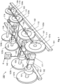
- FIG. 1 we see a schematic illustration of a rail vehicle 100 equipped with a controller 140 according to one embodiment of the invention.
- the rail vehicle 100 may be any kind of rail bound vehicle, such as a locomotive, a freight car, a goods wagon, a passenger car/coach, a railcar/railbus, and/or any combination thereof.
- the controller 140 is arranged to control a set of electrically operated brake units, here exemplified as 171, 172, 173 and 174 respectively, of the rail vehicle 100.
- the controller 140 is configured to receive a brake command B, for example from a driver's cabin or an emergency functionality of the rail vehicle 100, which for example may be passenger-activated with a bypass option.
- the controller 140 is configured to control each of the brake units 171, 172, 173 and 174 to apply a respective brake force to a respective rotating member 111, 112, 113 and 114.
- the rotating members 111, 112, 113 and 114 respectively are mechanically linked to the wheels of the rail vehicle 100.
- the wheels are exemplified by 121a, 121b, 122a, 122b, 123a, 123b, 124a and 124b respectively.
- each pair of wheels is mounted on a common wheel axle, so that they both rotate together with the wheel axle; or each wheel is mounted on a separate wheel axle, so that it may rotate independently from any other wheel.
- the brake forces applied to the respective rotating members 111, 112, 113 and 114 cause the rail vehicle 100 to reduce its speed.
- the controller 140 is also configured to repeatedly check whether the brake unit fulfills an operability criterion.
- the operability criterion may specify that the brake unit is capable of producing a brake force above a threshold level. If the operability criterion is fulfilled, the brake unit is considered to be faultless OK. If, however, the operability criterion is not fulfilled, the brake unit is considered to be faulty F.
- the controller 140 in response to the brake command B, is configured to control the faultless OK brake units, say 172, 173 and 174, to apply the respective increased brake force to compensate for the faulty F brake unit, say 171, until one or both of the below occurs:
- the controller 140 must check if the faultless OK brake units are deemed capable to compensate for the faulty F brake units; and in the latter case the brake capacity must be reassessed.
- the controller 140 is configured to estimate, based on the adhesion parameter ⁇ m, if it is possible to further increase a respective brake force of each of the faultless OK brake units, say 173 and 174, to compensate also for the at least one additional to be faulty F brake unit 172. If such a further increase is estimated to be possible, in response to the brake command B, the control unit 140 is configured to control the faultless OK brake units, 173 and 174, to apply a respective brake force to the respective rotating members, which respective brake force is increased to compensate also for the additional faulty F brake unit 172.
- the controller 140 if the controller 140 estimates that for the subsequently determined adhesion parameter ⁇ m it is not possible to increase the respective brake force of each of the faultless OK brake units 173 and 174 to compensate for the faulty F brake units 171 and 172, the controller 140 is further configured to recalculate a braking capacity for the rail vehicle 100.
- the recalculated braking capacity is based on the faultless OK brake units and 174 and the adhesion parameter ⁇ m.
- the controller 140 is further configured to recalculate a braking capacity for the rail vehicle 100.
- the recalculated braking capacity is based on the faultless OK brake units and 174 and the adhesion parameter ⁇ m.
- the adhesion parameter ⁇ m Preferably, in such a case, i.e.
- the controller 140 is also configured to emit an alarm signal A, for example informing the train driver of the updated braking capacity, for storage in a log file and/or for forwarding to a monitoring functionality in the rail vehicle and/or a central site.
- the alarm signal A and/or the updated braking capacity may preferably be transmitted to a control mechanism, such as an automatic train protection (ATP) system, e.g. ETCS (European Train Control System).
- ATP automatic train protection
- ETCS European Train Control System
- FIG. 3 shows a graph over an example of how a kinetic friction coefficient ⁇ k may be expressed as a function of a wheel slippage s.
- the wheel slippage s is understood to either designate a spinning motion of a wheel relative to the rail or a sliding motion of the wheel relative to the rail.
- the wheel slippage s is applicable to an acceleration scenario as well as a retardation ditto.
- the kinetic friction coefficient ⁇ k increases relatively proportionally with increasing wheel slippage s.
- the kinetic friction coefficient ⁇ k levels out somewhat.
- the friction coefficient peak value ⁇ e is associated with an optimal wheel slippage s e after which a further increase of wheel slippage s results in a gradually reduced, and then almost constant kinetic friction coefficient ⁇ k .
- the controller 140 is configured to determine a parameter ⁇ m that reflects the friction coefficient between at least one of the rail vehicle's 100 wheels and at least one respective rail 191 and/or 192 upon which the rail vehicle 100 travels.
- the peak value ⁇ e should be derived.
- an estimate of the peak value ⁇ e may be derived as follows.
- between the rotational speed of a specific driven wheel axle 131 and an average rotational speed ⁇ a of all the rail vehicle's 100 wheel axles in a driving subset of axles except the specific driven wheel axle 131 exceeds the threshold value, this corresponds to a situation where the wheels 121a and 121b on the specific driven wheel axle 131 experience a wheel slippage s m near the optimal wheel slippage s e .
- the peak value ⁇ e of the kinetic friction coefficient ⁇ k may be estimated relatively accurately; and the proximity of wheel slippage s m to the optimal wheel slippage s e is ensured by said threshold value for the absolute difference
- the controller 140 is configured to estimate if it is possible to increase a respective brake force of each of the faultless OK brake units, say 172, 173 and 174 respectively, to compensate for any faulty F brake unit, say 171. Moreover, if such an increase is estimated to be possible, in response to the brake command B, the controller 140 is configured to control the faultless OK brake units to apply a respective brake force to the respective rotating members, which respective brake force is increased to compensate for any faulty brake units.
- the controller 140 is configured to estimate if it is possible to increase a respective brake force of each of the faultless OK brake units to compensate for the faulty F brake units on the basis of the total weight m tot of the rail vehicle 100. Therefore, the controller 140 may be configured to estimate the total current weight m tot of the rail vehicle 100, i.e. the dynamic weight, as will be described below. This means that the controller 140 takes into account the instantaneous kinetic energy of the rail vehicle 100, i.e. the calculations consider the gross weight of the rail vehicle 100 and a current load weight thereon.
- the controller 140 is preferably arranged to estimate the different axle weights of the rail vehicle 100.
- Figure 1 exemplifies four such wheel axles in the form of 131, 132, 133 and 134 respectively.
- a set of drive units 101, 102 and 103 is configured to apply a respective traction force to each wheel axle in a driving subset of the wheel axles 131, 132 and 133, such that the rail vehicle 100 accelerates.
- the rail vehicle 100 contains a set of drive units 101, 102 and 103 respectively configured to apply a respective traction force to each of the wheel axles 131, 132 and 133 in the driving subset of the wheel axles.
- the controller 140 is configured to obtain a power signal P m indicating an amount of power being produced by the set of drive units 101, 102 and 103 when accelerating the rail vehicle 100 from a first speed v 1 to a second speed v 2 , for example from a standstill to 10 km/h.
- the power signal P m may equally well be received during acceleration of the rail vehicle 100 between any other two speed levels.
- the controller 140 is configured to obtain a speed signal indicating respective values of the first and second speeds v 1 and v 2 .
- controller 140 is further configured to:
- one or more of the rail vehicle's 100 wheel axles may be non-driven, i.e. not be comprised in the driving subset of the wheel axles 131, 132 and 133.
- the controller 140 is further configured execute the below procedure.
- the controller 140 is further configured to repeat steps (e) to (g) for each of the non-driven wheel axles, and based thereon estimate a respective fraction m 4 of the overall weight m tot carried by each of the non-driven wheel axles.
- the controller 140 may be configured to generate a control message ctrl A to make the acceleration controllers 161, 162 and 162 produce acceleration control signals A1, A2 and A3 to the drive units 101, 102 and 103 respectively, such that an average drive force applied to the wheel axles 132, and 133 except the specific wheel axles 131 is gradually decreased when the drive force applied to the specific wheel axle 131 is gradually increased.
- the driving on the other wheel axles 132 and 133 compensate for the somewhat excessive drive force applied to the specific wheel axle 131.
- this compensation is temporally matched.
- the controller 140 is configured to generate the control message ctrl A to cause the acceleration controllers 161, 162 and 162 to produce acceleration control signals A1, A2 and A3 to the drive units 101, 102 and 103 such that, at each point in time, the gradual decrease of the average drive force applied to the wheel axles 132 and 133 except the specific wheel axles 131 corresponds to the gradual increase of the drive force applied to the specific wheel axle 131. Namely, thereby the deviating drive force applied to specific wheel axle 131 is masked by the opposite deviation represented by the drive force applied to the wheel axles 132 and 133 in the driving subset.
- the drive unit 101 is configured to receive the acceleration control signal A1 from the acceleration controller 161, which, in turn, operates in response to the control message ctrl A from the controller 140.
- the acceleration control signal A1 may for example be transmitted via the data bus 150.
- the drive unit 101 is configured to drive the wheel axle 131.
- the drive unit 101 may contain at least one electric motor whose generated traction force depends on a magnitude of an electric current fed to it.
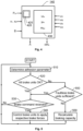
- FIG. 4 shows a block diagram of the controller 140 according to one embodiment of the invention.
- the controller 140 includes processing circuitry in the form of at least one processor 430 and a memory unit 420, i.e. non-volatile data carrier, storing a computer program 425, which, in turn, contains software for making the at least one processor 430 execute the actions mentioned in this disclosure when the computer program 425 is run on the at least one processor 430.
- the controller 140 contains input interfaces configured to receive the brake command B, the power signal P m , the speed signal expressing the speeds v 1 and v 2 respectively and the wheel speed signals ⁇ 1 , ⁇ 2 , ⁇ 3 and ⁇ 4 indicating the rotational speeds of the wheel axles in a driving subset of wheel axles 131, 132, 133 and 134 respectively. Further, the controller 140 contains an output interface configured to provide the control signal ctrl A to enable the acceleration controllers to cause its associated drive unit 101, 102 and 103 respectively to produce a respective traction force in response to the acceleration control signals A1, A2 and A3.
- the respective traction force are based on the respective fraction m 1 , m 2 or m 3 of the overall weight m tot applicable to the wheel axle in question 131, 132 or 133 respectively.
- controller 140 contains an output interface configured to provide the alarm signal A if the braking capacity is recalculated because it has been determined that the faultless OK brake units cannot to compensate for the faulty F brake units.
- an adhesion parameter ⁇ m is determined, which reflects a friction coefficient ⁇ e between at least one wheel of the rail vehicle and at least one rail upon which the rail vehicle travels.
- a step 520 thereafter checks if all the brake units fulfills an operability criterion. If so, a step 530 follows; and otherwise, the procedure continues to a step 550.
- Step 530 checks if a brake command has been received. If so, s step 540 follows; and otherwise, the procedure loops back to step 510.
- step 540 the faultless brake units are controlled to apply a respective brake force to respective rotating members being mechanically linked to the rail vehicle's wheels so as to reduce the rail vehicle's speed according to the received brake command.
- step 560 a braking capacity for the rail vehicle is recalculated based on the faultless brake units and the adhesion parameter ⁇ m. Thereafter, the procedure loops back to step 510.
- All of the process steps, as well as any sub-sequence of steps, described with reference to Figure 5 may be controlled by means of a programmed processor.
- the embodiments of the invention described above with reference to the drawings comprise processor and processes performed in at least one processor, the invention thus also extends to computer programs, particularly computer programs on or in a carrier, adapted for putting the invention into practice.
- the program may be in the form of source code, object code, a code intermediate source and object code such as in partially compiled form, or in any other form suitable for use in the implementation of the process according to the invention.
- the program may either be a part of an operating system, or be a separate application.
- the carrier may be any entity or device capable of carrying the program.
- the carrier may comprise a storage medium, such as a Flash memory, a ROM (Read Only Memory), for example a DVD (Digital Video/Versatile Disk), a CD (Compact Disc) or a semiconductor ROM, an EPROM (Erasable Programmable Read-Only Memory), an EEPROM (Electrically Erasable Programmable Read-Only Memory), or a magnetic recording medium, for example a floppy disc or hard disc.
- the carrier may be a transmissible carrier such as an electrical or optical signal which may be conveyed via electrical or optical cable or by radio or by other means.
- the carrier When the program is embodied in a signal, which may be conveyed, directly by a cable or other device or means, the carrier may be constituted by such cable or device or means.
- the carrier may be an integrated circuit in which the program is embedded, the integrated circuit being adapted for performing, or for use in the performance of, the relevant processes.
Landscapes
- Engineering & Computer Science (AREA)
- Transportation (AREA)
- Mechanical Engineering (AREA)
- Electric Propulsion And Braking For Vehicles (AREA)
- Regulating Braking Force (AREA)
- Valves And Accessory Devices For Braking Systems (AREA)
Priority Applications (3)
| Application Number | Priority Date | Filing Date | Title |
|---|---|---|---|
| EP23192972.0A EP4512673A1 (de) | 2023-08-23 | 2023-08-23 | Steuergerät zur steuerung von schienenfahrzeugbremseinheiten, computerimplementiertes verfahren dafür, computerprogramm und nichtflüchtiger datenträger |
| PCT/EP2024/067077 WO2025040282A1 (en) | 2023-08-23 | 2024-06-19 | Controller for controlling rail vehicle brake units, computer-implemented method therefor, computer program and non-volatile data carrier |
| CN202480054135.8A CN121729346A (zh) | 2023-08-23 | 2024-06-19 | 用于控制轨道车辆制动单元的控制器、其计算机实现方法、计算机程序及非易失性数据载体 |
Applications Claiming Priority (1)
| Application Number | Priority Date | Filing Date | Title |
|---|---|---|---|
| EP23192972.0A EP4512673A1 (de) | 2023-08-23 | 2023-08-23 | Steuergerät zur steuerung von schienenfahrzeugbremseinheiten, computerimplementiertes verfahren dafür, computerprogramm und nichtflüchtiger datenträger |
Publications (1)
| Publication Number | Publication Date |
|---|---|
| EP4512673A1 true EP4512673A1 (de) | 2025-02-26 |
Family
ID=87762431
Family Applications (1)
| Application Number | Title | Priority Date | Filing Date |
|---|---|---|---|
| EP23192972.0A Pending EP4512673A1 (de) | 2023-08-23 | 2023-08-23 | Steuergerät zur steuerung von schienenfahrzeugbremseinheiten, computerimplementiertes verfahren dafür, computerprogramm und nichtflüchtiger datenträger |
Country Status (3)
| Country | Link |
|---|---|
| EP (1) | EP4512673A1 (de) |
| CN (1) | CN121729346A (de) |
| WO (1) | WO2025040282A1 (de) |
Citations (6)
| Publication number | Priority date | Publication date | Assignee | Title |
|---|---|---|---|---|
| US6062657A (en) | 1998-04-21 | 2000-05-16 | Daimlerchrysler Rail Systems (North America) Inc. | Brake failure compensation system and method |
| US6520599B2 (en) | 2001-05-05 | 2003-02-18 | Westinghouse Air Brake Technologies Corporation | Four port variable load valve weigh system for a brake pipe controlled brake system |
| US6549842B1 (en) * | 2001-10-31 | 2003-04-15 | Delphi Technologies, Inc. | Method and apparatus for determining an individual wheel surface coefficient of adhesion |
| US20050057095A1 (en) * | 2003-09-17 | 2005-03-17 | Delphi Technologies Inc. | Control of brake-and steer-by-wire systems during brake failure |
| US7597408B2 (en) | 2006-11-20 | 2009-10-06 | Hyundai Motor Company | Method for compensating regenerative braking amount when regenerative braking of vehicle fails |
| EP3554904A1 (de) | 2016-12-16 | 2019-10-23 | New York Air Brake, LLC | Intelligentes bremssteuerungssystem für lokomotive |
-
2023
- 2023-08-23 EP EP23192972.0A patent/EP4512673A1/de active Pending
-
2024
- 2024-06-19 WO PCT/EP2024/067077 patent/WO2025040282A1/en active Pending
- 2024-06-19 CN CN202480054135.8A patent/CN121729346A/zh active Pending
Patent Citations (6)
| Publication number | Priority date | Publication date | Assignee | Title |
|---|---|---|---|---|
| US6062657A (en) | 1998-04-21 | 2000-05-16 | Daimlerchrysler Rail Systems (North America) Inc. | Brake failure compensation system and method |
| US6520599B2 (en) | 2001-05-05 | 2003-02-18 | Westinghouse Air Brake Technologies Corporation | Four port variable load valve weigh system for a brake pipe controlled brake system |
| US6549842B1 (en) * | 2001-10-31 | 2003-04-15 | Delphi Technologies, Inc. | Method and apparatus for determining an individual wheel surface coefficient of adhesion |
| US20050057095A1 (en) * | 2003-09-17 | 2005-03-17 | Delphi Technologies Inc. | Control of brake-and steer-by-wire systems during brake failure |
| US7597408B2 (en) | 2006-11-20 | 2009-10-06 | Hyundai Motor Company | Method for compensating regenerative braking amount when regenerative braking of vehicle fails |
| EP3554904A1 (de) | 2016-12-16 | 2019-10-23 | New York Air Brake, LLC | Intelligentes bremssteuerungssystem für lokomotive |
Also Published As
| Publication number | Publication date |
|---|---|
| WO2025040282A1 (en) | 2025-02-27 |
| WO2025040282A8 (en) | 2025-07-17 |
| CN121729346A (zh) | 2026-03-24 |
Similar Documents
| Publication | Publication Date | Title |
|---|---|---|
| EP1569815B1 (de) | Bremssystem und bremssteuerverfahren | |
| CN111959467B (zh) | 一种轨道车辆电机械制动防滑控制系统及方法 | |
| CN103813948B (zh) | 用于车辆的制动控制方法及其装置 | |
| US8577522B2 (en) | Method for monitoring at least one system parameter which influences the operating behaviour of vehicles or trains of vehicles | |
| CN110435621B (zh) | 一种列车的电空混合制动控制方法 | |
| CN111959466B (zh) | 一种轨道车辆电机械制动系统 | |
| CN110072747B (zh) | 智能机车制动器控制系统 | |
| US11654876B2 (en) | Braking control system | |
| CN112060919B (zh) | 轨道车辆制动融合控制系统及方法 | |
| CN111959468B (zh) | 一种轨道车辆电机械制动力控制方法 | |
| US20120197476A1 (en) | Graduated vehicle braking | |
| US6866347B2 (en) | Locomotive brake pipe valve cut-out failure detection and correction | |
| JP7634011B2 (ja) | 安全な追加ブレーキ機能を実行するためのブレーキシステム | |
| EP4512673A1 (de) | Steuergerät zur steuerung von schienenfahrzeugbremseinheiten, computerimplementiertes verfahren dafür, computerprogramm und nichtflüchtiger datenträger | |
| EP2623361A1 (de) | Bremssteuervorrichtung für fahrzeuge und bremssteuervorrichtung für mehrwagenzüge | |
| US6062657A (en) | Brake failure compensation system and method | |
| CN109070854B (zh) | 用于开环控制或闭环控制制动设备的方法和装置 | |
| EP2226226A2 (de) | Bremsverfahren durch Kombinieren von elektrodynamischen mit mechanischen Bremsen für die Notbremsung | |
| JP2025513078A (ja) | 鉄道車両用の制動システムおよび制動方法 | |
| JP2025512086A (ja) | 鉄道車両用の制動システムおよび制動方法 | |
| CN119013175A (zh) | 用于轨道车辆的制动系统和制动方法 | |
| CN119013180A (zh) | 用于轨道车辆的制动系统和制动方法 | |
| EP4556330A1 (de) | Schienenfahrzeug, steuergerät für elektrisch betriebene bremseinheiten, computerimplementiertes verfahren dafür, computerprogramm und nichtflüchtiger datenträger | |
| CN114670897A (zh) | 基于两级控制架构的牵引制动融合系统及方法 | |
| CN116829400A (zh) | 制动力矩调节装置、制动系统和用于调节制动力矩的方法 |
Legal Events
| Date | Code | Title | Description |
|---|---|---|---|
| PUAI | Public reference made under article 153(3) epc to a published international application that has entered the european phase |
Free format text: ORIGINAL CODE: 0009012 |
|
| STAA | Information on the status of an ep patent application or granted ep patent |
Free format text: STATUS: THE APPLICATION HAS BEEN PUBLISHED |
|
| AK | Designated contracting states |
Kind code of ref document: A1 Designated state(s): AL AT BE BG CH CY CZ DE DK EE ES FI FR GB GR HR HU IE IS IT LI LT LU LV MC ME MK MT NL NO PL PT RO RS SE SI SK SM TR |
|
| STAA | Information on the status of an ep patent application or granted ep patent |
Free format text: STATUS: REQUEST FOR EXAMINATION WAS MADE |
|
| 17P | Request for examination filed |
Effective date: 20250319 |