EP4512644A1 - Thermal management integrated module, thermal management system, and vehicle - Google Patents
Thermal management integrated module, thermal management system, and vehicle Download PDFInfo
- Publication number
- EP4512644A1 EP4512644A1 EP24193899.2A EP24193899A EP4512644A1 EP 4512644 A1 EP4512644 A1 EP 4512644A1 EP 24193899 A EP24193899 A EP 24193899A EP 4512644 A1 EP4512644 A1 EP 4512644A1
- Authority
- EP
- European Patent Office
- Prior art keywords
- refrigerant
- substrate
- thermal management
- heat exchanger
- water path
- Prior art date
- Legal status (The legal status is an assumption and is not a legal conclusion. Google has not performed a legal analysis and makes no representation as to the accuracy of the status listed.)
- Pending
Links
Images







Classifications
-
- B—PERFORMING OPERATIONS; TRANSPORTING
- B60—VEHICLES IN GENERAL
- B60H—ARRANGEMENTS OF HEATING, COOLING, VENTILATING OR OTHER AIR-TREATING DEVICES SPECIALLY ADAPTED FOR PASSENGER OR GOODS SPACES OF VEHICLES
- B60H1/00—Heating, cooling or ventilating devices
- B60H1/00321—Heat exchangers for air-conditioning devices
- B60H1/00342—Heat exchangers for air-conditioning devices of the liquid-liquid type
-
- B—PERFORMING OPERATIONS; TRANSPORTING
- B60—VEHICLES IN GENERAL
- B60H—ARRANGEMENTS OF HEATING, COOLING, VENTILATING OR OTHER AIR-TREATING DEVICES SPECIALLY ADAPTED FOR PASSENGER OR GOODS SPACES OF VEHICLES
- B60H1/00—Heating, cooling or ventilating devices
- B60H1/00271—HVAC devices specially adapted for particular vehicle parts or components and being connected to the vehicle HVAC unit
- B60H1/00278—HVAC devices specially adapted for particular vehicle parts or components and being connected to the vehicle HVAC unit for the battery
-
- B—PERFORMING OPERATIONS; TRANSPORTING
- B60—VEHICLES IN GENERAL
- B60H—ARRANGEMENTS OF HEATING, COOLING, VENTILATING OR OTHER AIR-TREATING DEVICES SPECIALLY ADAPTED FOR PASSENGER OR GOODS SPACES OF VEHICLES
- B60H1/00—Heating, cooling or ventilating devices
- B60H1/00642—Control systems or circuits; Control members or indication devices for heating, cooling or ventilating devices
- B60H1/00814—Control systems or circuits characterised by their output, for controlling particular components of the heating, cooling or ventilating installation
- B60H1/00878—Control systems or circuits characterised by their output, for controlling particular components of the heating, cooling or ventilating installation the components being temperature regulating devices
- B60H1/00885—Controlling the flow of heating or cooling liquid, e.g. valves or pumps
-
- B—PERFORMING OPERATIONS; TRANSPORTING
- B60—VEHICLES IN GENERAL
- B60H—ARRANGEMENTS OF HEATING, COOLING, VENTILATING OR OTHER AIR-TREATING DEVICES SPECIALLY ADAPTED FOR PASSENGER OR GOODS SPACES OF VEHICLES
- B60H1/00—Heating, cooling or ventilating devices
- B60H1/32—Cooling devices
- B60H1/3204—Cooling devices using compression
- B60H1/3229—Cooling devices using compression characterised by constructional features, e.g. housings, mountings, conversion systems
-
- F—MECHANICAL ENGINEERING; LIGHTING; HEATING; WEAPONS; BLASTING
- F28—HEAT EXCHANGE IN GENERAL
- F28D—HEAT-EXCHANGE APPARATUS, NOT PROVIDED FOR IN ANOTHER SUBCLASS, IN WHICH THE HEAT-EXCHANGE MEDIA DO NOT COME INTO DIRECT CONTACT
- F28D9/00—Heat-exchange apparatus having stationary plate-like or laminated conduit assemblies for both heat-exchange media, the media being in contact with different sides of a conduit wall
- F28D9/0031—Heat-exchange apparatus having stationary plate-like or laminated conduit assemblies for both heat-exchange media, the media being in contact with different sides of a conduit wall the conduits for one heat-exchange medium being formed by paired plates touching each other
- F28D9/0043—Heat-exchange apparatus having stationary plate-like or laminated conduit assemblies for both heat-exchange media, the media being in contact with different sides of a conduit wall the conduits for one heat-exchange medium being formed by paired plates touching each other the plates having openings therein for circulation of at least one heat-exchange medium from one conduit to another
- F28D9/005—Heat-exchange apparatus having stationary plate-like or laminated conduit assemblies for both heat-exchange media, the media being in contact with different sides of a conduit wall the conduits for one heat-exchange medium being formed by paired plates touching each other the plates having openings therein for circulation of at least one heat-exchange medium from one conduit to another the plates having openings therein for both heat-exchange media
-
- F—MECHANICAL ENGINEERING; LIGHTING; HEATING; WEAPONS; BLASTING
- F28—HEAT EXCHANGE IN GENERAL
- F28F—DETAILS OF HEAT-EXCHANGE AND HEAT-TRANSFER APPARATUS, OF GENERAL APPLICATION
- F28F9/00—Casings; Header boxes; Auxiliary supports for elements; Auxiliary members within casings
- F28F9/22—Arrangements for directing heat-exchange media into successive compartments, e.g. arrangements of guide plates
-
- F—MECHANICAL ENGINEERING; LIGHTING; HEATING; WEAPONS; BLASTING
- F28—HEAT EXCHANGE IN GENERAL
- F28D—HEAT-EXCHANGE APPARATUS, NOT PROVIDED FOR IN ANOTHER SUBCLASS, IN WHICH THE HEAT-EXCHANGE MEDIA DO NOT COME INTO DIRECT CONTACT
- F28D21/00—Heat-exchange apparatus not covered by any of the groups F28D1/00 - F28D20/00
- F28D2021/0019—Other heat exchangers for particular applications; Heat exchange systems not otherwise provided for
- F28D2021/008—Other heat exchangers for particular applications; Heat exchange systems not otherwise provided for for vehicles
-
- Y—GENERAL TAGGING OF NEW TECHNOLOGICAL DEVELOPMENTS; GENERAL TAGGING OF CROSS-SECTIONAL TECHNOLOGIES SPANNING OVER SEVERAL SECTIONS OF THE IPC; TECHNICAL SUBJECTS COVERED BY FORMER USPC CROSS-REFERENCE ART COLLECTIONS [XRACs] AND DIGESTS
- Y02—TECHNOLOGIES OR APPLICATIONS FOR MITIGATION OR ADAPTATION AGAINST CLIMATE CHANGE
- Y02E—REDUCTION OF GREENHOUSE GAS [GHG] EMISSIONS, RELATED TO ENERGY GENERATION, TRANSMISSION OR DISTRIBUTION
- Y02E60/00—Enabling technologies; Technologies with a potential or indirect contribution to GHG emissions mitigation
- Y02E60/10—Energy storage using batteries
Definitions
- This application relates to the field of thermal management technologies, and in particular, to a thermal management integrated module, a thermal management system, and a vehicle.
- the thermal management system in the related technology includes a water-side component, a refrigerant component, and a heat exchanger.
- the water-side component includes a water path substrate and a water tank.
- the refrigerant component includes a refrigerant substrate.
- the water-side component, the refrigerant component, and the heat exchanger are integrated together.
- the heat exchanger is integrated on a side that is of the refrigerant substrate and that is away from the water-side component. Therefore, a hole needs to be dug on the refrigerant substrate to place the heat exchanger. This causes a waste of a material of the refrigerant substrate.
- an extension area of the refrigerant substrate is excessively large. This is not conducive to miniaturization.
- a size of the water tank is large, and there is a specific requirement for a mounting position of the water tank, a mounting environment of the thermal management system is limited, and environmental adaptability is reduced.
- Embodiments of this application provide a thermal management integrated module, a thermal management system, and a vehicle, to implement miniaturization of the thermal management integrated module and improve structural strength of a refrigerant substrate.
- an embodiment of this application provides a thermal management integrated module, including a water-side component, a refrigerant component, and a heat exchanger.
- the water-side component and the refrigerant component are respectively located on two opposite sides of the heat exchanger.
- the water-side component includes a water path substrate.
- a plumbing of the water path substrate is configured to accommodate a first medium.
- the refrigerant component includes a refrigerant substrate.
- a plumbing of the refrigerant substrate is configured to accommodate a second medium.
- the heat exchanger is located in a gap space formed by the water path substrate and the refrigerant substrate.
- Both the plumbing of the water path substrate and the plumbing of the refrigerant substrate communicate with a flow channel of the heat exchanger, so that the first medium exchanges heat with the second medium inside the heat exchanger.
- the water-side component has a first external connection port.
- the first external connection port is configured to connect to a water tank in a thermal management system through a coolant hose.
- the heat exchanger is located in the gap space formed by the water path substrate and the refrigerant substrate, to form a "sandwich" architecture, and there is no need to provide a through hole on the refrigerant substrate to place the heat exchanger. In this way, a base material for manufacturing the refrigerant substrate can be reduced, and costs can be reduced.
- the through hole provided on the refrigerant substrate to place the heat exchanger is reduced, strength of the refrigerant substrate can be improved, and a size of the refrigerant substrate can be reduced.
- the refrigerant substrate is miniaturized, so that the strength of the refrigerant substrate can also be improved.
- the water tank may communicate with the first external connection port through the coolant hose, so that the water tank and the thermal management integrated module cooperate with each other in functions and are decoupled from each other in positions, to improve use performance of the water tank and the thermal management integrated module.
- the thermal management integrated module in this embodiment can be used in different environments, for example, can be used in both a vehicle and an energy storage system.
- all functional components of the water-side component are distributed at other positions of the water path substrate other than a surface that is of the water path substrate and that faces the heat exchanger. Because the surface that is of the water path substrate and that faces the heat exchanger corresponds to the heat exchanger, all the functional components of the water-side component are distributed at the other positions of the water path substrate other than the surface that is of the water path substrate and that faces the heat exchanger. In this way, a size of the water path substrate can match a size of the heat exchanger as much as possible. This miniaturizes the water-side component.
- all functional components of the refrigerant component are distributed at other positions of the refrigerant substrate other than a surface that is of the refrigerant substrate and that faces the heat exchanger. Because a second surface corresponds to the heat exchanger, all the functional components of the refrigerant component are distributed at the other positions of the refrigerant substrate other than the surface that is of the refrigerant substrate and that faces the heat exchanger. In this way, a size of the refrigerant substrate can match a size of the heat exchanger as much as possible. This miniaturizes the water-side component.
- the water path substrate is provided with an inner cavity, and all the functional components of the water-side component are mounted in the inner cavity and/or on a side that is of the water path substrate and that is away from the heat exchanger.
- this can facilitate miniaturization of the thermal management integrated module.
- the plumbing in the water path substrate can be in a 3D architecture. This can effectively use three-dimensional space, reduce a size that is of the water path substrate and that is in a direction perpendicular to a first direction, and facilitate miniaturization of the water-side component.
- the water-side component, the heat exchanger, and the refrigerant component are sequentially arranged in a first direction.
- a projection that is of the heat exchanger and that is on the water path substrate is a first projection
- a projection that is of the heat exchanger and that is on the refrigerant substrate is a second projection.
- a distance between an edge of the first projection and an edge of the water path substrate is less than a first threshold
- a distance between an edge of the second projection and an edge of the refrigerant substrate is less than a second threshold.
- the water path substrate can be fully miniaturized, and a size of the water path substrate is close to a size of the first projection of the heat exchanger. Because the edge of the second projection is adjacent to the edge of the refrigerant substrate, the refrigerant substrate can be fully miniaturized, and a size of the refrigerant substrate is close to a size of the second projection of the heat exchanger.
- the surface that is of the water path substrate and that faces the heat exchanger is a first surface
- the surface that is of the refrigerant substrate and that faces the heat exchanger is a second surface
- an outer contour shape of the first surface is the same as an outer contour shape of the second surface. Because the outer contour shape of the first surface is the same as the outer contour shape of the second surface, the entire thermal management integrated module in this embodiment is more structured, so that miniaturization of the thermal management integrated module is facilitated, and mounting convenience can be improved.
- the water-side component, the heat exchanger, and the refrigerant component are sequentially arranged in the first direction.
- the first direction at least 75% of an area of a side that is of the water path substrate and that faces the heat exchanger directly faces the heat exchanger.
- a lower limit of a size of the thermal management integrated module is determined by the heat exchanger. Because the at least 75% of the area of the side that is of the water path substrate and that faces the heat exchanger directly faces the heat exchanger, the water path substrate can be appropriately miniaturized, so that the thermal management integrated module can be appropriately miniaturized. Because the at least 75% of the area of the side that is of the refrigerant substrate and that faces the heat exchanger directly faces the heat exchanger, the refrigerant substrate can be appropriately miniaturized, so that the thermal management integrated module can be appropriately miniaturized.
- At least a part of the heat exchanger is in contact with the water path substrate, and at least a part of the heat exchanger is in contact with the refrigerant substrate. Because two sides that are of a heat exchange component and that are in the first direction are respectively in contact with the water path substrate and the refrigerant substrate, it can be ensured that a distance between the water path substrate and the refrigerant substrate is short, and the gap space between the water path substrate and the refrigerant substrate is only used to accommodate the heat exchanger. This helps implement a small size of the entire thermal management integrated module.
- a water path port is disposed on the side that is of the water path substrate and that faces the heat exchanger
- a water path connection port is disposed on the side that is of the heat exchanger and that faces the water path substrate
- the water path port is connected to the water path connection port.
- the water path port is located on the side that is of the water path substrate and that faces the heat exchanger
- the water path connection port is located on the side that is of the heat exchanger and that faces the water path substrate, to conveniently connect the water path substrate to the water path connection port.
- a length of a coolant hose that connects the water path substrate to the heat exchanger can be reduced, to facilitate miniaturization of the thermal management integrated module.
- the water path port is connected to the water path connection port through a flexible coolant hose. Because the water path port is connected to the water path connection port through the flexible coolant hose, when the water path substrate deforms, hard contact does not occur on the water path port and the water path connection port, and the water path port and the water path connection port are not damaged, to avoid a leakage from the water path port and the water path connection port.
- some functional components are water pumps, some functional components are temperature sensors, and the remaining functional components are multi-port valves. Because the water pump and the multi-port valve are small in size, a miniaturization design of the water-side component can be facilitated.
- the water path substrate is provided with an inner cavity.
- the multi-port valve is located in the inner cavity.
- a plurality of water connection ports of the multi-port valve correspondingly communicate with a plurality of plumbings of the water path substrate. Because at least a part of the multi-port valve is disposed inside the water path substrate, the plumbing in the water path substrate can be in a 3D three-dimensional architecture. This can effectively use three-dimensional space, reduce a size that is of the water path substrate and that is in a direction perpendicular to the first direction, and facilitate miniaturization of the water-side component.
- all functional components of the refrigerant component are mounted on a side that is of the refrigerant substrate and that is away from the heat exchange component.
- some functional components are expansion valves
- some functional components are solenoid valves
- some functional components are check valves
- some functional components are temperature sensors
- the remaining functional components are temperature and pressure sensors.
- Second functional components include only the expansion valve, the solenoid valve, the check valve, and the temperature and pressure sensor, and the expansion valve, the solenoid valve, the check valve, and the temperature and pressure sensor are all small in size. Therefore, the integrated thermal management integrated module has a small size. This facilitates miniaturization of the thermal management integrated module.
- the water path substrate and/or the refrigerant substrate each include/includes a fastening structure.
- the fastening structure is configured to fasten the thermal management integrated module in a use environment.
- the water path substrate and/or the refrigerant substrate may be fastened, by using the fastening structure, in the use environment in which the water path substrate and/or the refrigerant substrate need/needs to be fastened, so that the thermal management integrated module in this embodiment is fastened in a use environment in which the thermal management integrated module needs to be fastened.
- a first plumbing, several first functional ports communicating with the first plumbing, a second plumbing, and several second functional ports communicating with the second plumbing are formed on the refrigerant substrate.
- the several first functional ports are connected to the check valve, the temperature and pressure sensor, and the expansion valve.
- the several second functional ports are connected to the check valve, the solenoid valve, the temperature and pressure sensor, and the expansion valve.
- the heat exchanger includes a condensation heat exchange component and an evaporation heat exchange component.
- the condensation heat exchange component includes a condensation inlet and a condensation outlet.
- the condensation inlet communicates with the second plumbing.
- the condensation outlet communicates with the first plumbing.
- the evaporation heat exchange component includes an evaporation inlet and an evaporation outlet.
- the evaporation inlet communicates with the first plumbing.
- the evaporation outlet is configured to be connected to an access of a gas-liquid separator in the thermal management system.
- the heat exchanger includes two heat exchange components.
- the two heat exchange components are disposed in parallel between the water path substrate and the refrigerant substrate.
- An end face that is of each heat exchange component and that faces the water path substrate has a longer side and a shorter side.
- the surface that is of the water path substrate and that faces the heat exchanger has a first side and a second side.
- the two heat exchange components are arranged in a second direction.
- the second direction is the same as an extension direction of the longer side.
- the first side corresponds to positions of the longer sides of the two heat exchange components.
- the second side of the water path substrate corresponds to a position of the shorter side of one of the heat exchange components.
- the heat exchanger includes two heat exchange components.
- the two heat exchange components are disposed in parallel between the water path substrate and the refrigerant substrate.
- An end face that is of each heat exchange component and that faces the water path substrate has a longer side and a shorter side.
- the surface that is of the water path substrate and that faces the heat exchanger has a first side and a second side.
- a width of the water-side component in a direction of the second side can be reduced.
- the thermal management integrated module in this implementation is suitable for being mounted in a thin and long mounting environment.
- the two heat exchange components are arranged in a third direction.
- the third direction is the same as an extension direction of the shorter side.
- the first side corresponds to positions of the shorter sides of the two heat exchange components.
- the second side of the water path substrate corresponds to a position of the longer side of one of the heat exchange components. In this embodiment, neither the first side nor the second side of the water path substrate is too large.
- the thermal management integrated module in this implementation is suitable for being mounted in a mounting environment with a length and a width that are similar to each other.
- the refrigerant component includes a second external connection port.
- the second external connection port is configured to be connected to a gas-liquid separator in the thermal management system through a coolant hose.
- the second external connection port is configured to be connected to the gas-liquid separator in the thermal management system through the coolant hose, so that a position of the thermal management integrated module in this embodiment can be decoupled from a position of the gas-liquid separator. This helps improve mounting environment adaptability of the gas-liquid separator and the thermal management integrated module, miniaturize the thermal management integrated module.
- this application provides a thermal management system, including a water tank, a gas-liquid separator, and the thermal management integrated module according to any implementation of the first aspect.
- the thermal management integrated module is connected to the water tank and the gas-liquid separator through coolant hoses.
- this application provides a vehicle, including a battery, a powertrain, and the foregoing thermal management system.
- the thermal management system is configured to perform thermal management on the battery and the powertrain.
- this application provides an energy storage system, including an energy storage battery and the foregoing thermal management system.
- the thermal management system is configured to perform thermal management on the energy storage battery.
- Z first direction; X: second direction; Y: third direction; 1000: vehicle; 1: thermal management system; 11: thermal management integrated module; 12: water tank; 13: gas-liquid separator; 14: compressor; 2: thermal management object; 100: water-side component; 110: water path substrate; 111: first surface; 112: upper surface; 1121: first plane; 1122: second plane; 1123: third plane; 113: side surface; 115: first side; 116: second side; 117: plumbing; 118: first external connection port; 120: first functional component; 130: water path port; 140: water pump; 150: multi-port valve; 1501: inner cavity; 151: valve body; 1511: water connection port; 152: valve core; 1521: groove; 153: actuator; 200: refrigerant component; 210: refrigerant substrate; 211: second surface; 212: annular side panel; 213: coolant hose; 214: first plumbing; 215: second plumbing; 216: first functional port; 217: second functional port;
- a process, method, system, product, or device that includes a list of steps or units is not necessarily limited to those steps or units that are expressly listed, but may include other steps or units that are not expressly listed or are inherent to the process, method, product, or device.
- Perpendicularity defined in this application is not limited to an absolute perpendicular intersection (an included angle is 90 degrees) relationship, a non-absolute perpendicular intersection relationship caused by factors such as an assembly tolerance, a design tolerance, and a structural flatness is allowed, and an error within a small angle range is allowed. For example, a relationship within an assembly angle range of 80 degrees to 100 degrees may be understood as the perpendicular relationship.
- Parallelism defined in this application is not limited to absolute parallelism.
- Parallel defined herein may be understood as basic parallelism, and non-absolute parallelism caused by factors such as an assembly tolerance, a design tolerance, and a structural flatness is allowed. The factors may cause a case in which a sliding cooperation part and a first door plate are not absolutely parallel, but this application also defines, as parallelism, the case in which the sliding cooperation part and the first door plate are not absolutely parallel.
- An embodiment of this application provides a thermal management system.
- the thermal management system in this embodiment of this application is applicable to the vehicle-mounted and the energy storage field.
- the thermal management system in this embodiment of this application may be used in an electric vehicle in the vehicle-mounted, and the electric vehicle is a transportation means driven by an electric power module .
- the electric power module may include, for example, a power distribution unit (PDU), a microcontroller unit (MCU), a mapped diagnostic context (MDC), and a motor.
- PDU power distribution unit
- MCU microcontroller unit
- MDC mapped diagnostic context
- the thermal management system in embodiments of this application may be used in a photovoltaic system, a wind power system, and the like in the energy storage field.
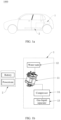
- FIG. 1a is a diagram of a structure of a vehicle 1000 according to an embodiment of this application.
- FIG. lb is an operating block diagram of a thermal management system 1 of the vehicle 1000 according to an embodiment of this application.
- the vehicle 1000 includes the thermal management system 1 and a thermal management object 2.
- the thermal management system 1 is configured to perform thermal management on the thermal management object 2. It may be understood that positions of the thermal management object 2 and the thermal management system 1 in the figure are merely examples, and do not indicate that the thermal management object 2 and the thermal management system 1 are definitely at the positions shown in the figure. The thermal management object 2 and the thermal management system 1 may alternatively be disposed at other positions.
- the thermal management object 2 includes one or more of a battery, a powertrain, and an electronic control module.
- a battery is configured to provide most of electric energy required by the vehicle 1000.
- the powertrain is configured to provide power for the vehicle 1000.
- the powertrain may include a motor, a transmission, a transmission system, and an exhaust system.
- the electronic control module is an overall system including elements such as an electronic control unit (ECU), a harness, and a sensor that are of the vehicle.
- the electronic control module may perform refined adjustment, control, and management on an automotive engine, the transmission, braking, and security control of the vehicle, to ensure smooth traveling and stability of the vehicle in various complex driving scenarios.
- the electronic control module of the vehicle is an important part of the vehicle, and has high requirements for matching, debugging, maintenance, upgrading, and the like of an electronic device.
- the thermal management system 1 is configured to monitor and control a temperature of the vehicle 1000, and maintain a normal operating temperature range of each part (for example, the battery, the powertrain, the electronic control module, and an interior of the vehicle) of the vehicle 1000, to improve performance, efficiency, and comfort of the vehicle 1000.
- a normal operating temperature range of each part for example, the battery, the powertrain, the electronic control module, and an interior of the vehicle
- the thermal management system 1 includes a thermal management integrated module 11, a water tank 12, and a gas-liquid separator 13.
- the water tank 12 is configured to provide circulated water for the thermal management integrated module 11. Because the water tank 12 is independent of the thermal management integrated module 11 and is connected to the thermal management integrated module 11 through a coolant hose, a position of the water tank 12 can be decoupled from a position of the thermal management integrated module 11. For example, the water tank 12 is placed at a higher position, and the thermal management integrated module 11 is placed at a lower position than that of the water tank 12. This can improve use performance of the water tank 12 and the thermal management integrated module 11, and further enable the thermal management integrated module 11 in this embodiment to be adapted to different environments, for example, the thermal management integrated module 11 can be used in both a vehicle and an energy storage system. In addition, the water tank 12 and the thermal management integrated module 11 are separately and independently disposed, so that the thermal management integrated module 11 is not affected by the water tank 12 with a large size. This facilitates miniaturization of the thermal management integrated module 11.
- a component with a large volume like the gas-liquid separator 13 may also be independent of the thermal management integrated module 11, and is connected to the thermal management integrated module 11 through a coolant hose, to facilitate miniaturization of the thermal management integrated module 11.
- a compressor 14 in the thermal management system 1 may also be disposed independently of the thermal management integrated module 11. Certainly, in some implementations, the compressor 14 may alternatively be integrated into the thermal management integrated module 11.
- FIG. 2 is an operating block diagram of a thermal management system 1 of an energy storage system according to an embodiment of this application.
- the energy storage system includes the thermal management system 1 and the thermal management object 2.
- the thermal management system 1 includes a thermal management integrated module 11, a water tank 12, and a gas-liquid separator 13.
- the thermal management object 2 in this embodiment is an energy storage battery, a power control system (PCS), a DC-DC converter, and the like.
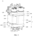
- FIG. 3 is a diagram of a structure of a thermal management integrated module 11 according to an embodiment of this application.
- FIG. 4 is an exploded diagram of the thermal management integrated module 11 in FIG. 3 .
- the thermal management integrated module 11 in this embodiment may be used in the thermal management systems 1 in embodiments in FIG. lb and FIG. 2 , or may be used in another thermal management system 1, for example, thermal management systems 1 in the electronic and medical fields.
- the thermal management integrated module 11 includes a water-side component 100, a refrigerant component 200, and a heat exchanger 300.
- the water-side component 100 in this embodiment is mainly configured to adjust and control flowing of a first medium in the system, to ensure normal operation of a device and temperature control.
- the first medium in the water-side component 100 may flow to positions such as a battery, a powertrain, and a control unit, to implement temperature control and adjustment on the battery, the powertrain, the control unit, and the like.
- the refrigerant component 200 in this embodiment is mainly configured to control a refrigerant to circulate in the system, to implement temperature adjustment through heat absorption and heat release.
- a main function of the heat exchanger 300 in this embodiment is to implement heat exchange.
- the heat exchanger 300 may be a condenser
- the heat exchanger 300 may alternatively be an evaporator.
- the heat exchanger 300 may alternatively include both a condenser and an evaporator.
- the water-side component 100 and the refrigerant component 200 are separately connected to the heat exchanger 300, so that heat exchange between the first medium (for example, water) flowing from the water-side component 100 to the heat exchanger 300 and a second medium (for example, a refrigerant) flowing from the refrigerant component 200 to the heat exchanger 300 is implemented by using the heat exchanger 300.
- first medium for example, water
- second medium for example, a refrigerant
- the water-side component 100 and the refrigerant component 200 are respectively located on two opposite sides of the heat exchanger 300, so that the water-side component 100, the refrigerant component 200, and the heat exchanger 300 are disposed in a "sandwich" architecture.
- a size of the refrigerant component 200 can be reduced, and connection stability of functional components of the refrigerant component 200 can further be improved.
- the water-side component 100 includes a water path substrate 110 and several functional components located on the water path substrate 110.
- the functional components of the water-side component 100 are a first functional component 120.
- the refrigerant component 200 includes a refrigerant substrate 210 and several functional components located on the refrigerant substrate 210.
- the functional component of the refrigerant components 200 are a second functional component 220.
- the heat exchanger 300 is located in a gap space formed by the water path substrate 110 and the refrigerant substrate 210, to form the "sandwich" architecture. This can facilitate miniaturization of the refrigerant substrate 210, save a material of the refrigerant substrate 210, and improve strength of the refrigerant substrate 210.
- the water path substrate 110 directly faces the refrigerant substrate 210 in a first direction Z.
- the first direction Z is also a direction in which the water-side component 100, the heat exchanger 300, and the refrigerant component 200 are sequentially arranged.
- the refrigerant substrate 210 does not need to be provided with a through hole for placing the heat exchanger 300, to save a base material for manufacturing the refrigerant substrate 210, and reduce costs.
- the refrigerant substrate 210 is not provided with a through hole for placing the heat exchanger 300, strength of the refrigerant substrate 210 is enhanced, and a size of the refrigerant substrate 210 is reduced.
- the refrigerant substrate 210 is miniaturized, so that the strength of the refrigerant substrate 210 can also be improved.
- a water path port 130 is disposed on a side that is of the water path substrate 110 and that faces the heat exchanger 300
- a water path connection port 310 is disposed on a side that is of the heat exchanger 300 and that faces the heat exchanger 300
- the water path substrate 110 is connected to the water path connection port 310 of the heat exchanger 300 through the water path port 130.
- the water path port 130 is located on the side that is of the water path substrate 110 and that faces the heat exchanger 300
- the water path connection port 310 is located on the side that is of the heat exchanger 300 and that faces the water path substrate 110, to conveniently connect the water path substrate 110 to the water path connection port 310.
- a length of a coolant hose 213 that connects the water path substrate 110 to the heat exchanger 300 can be reduced, to facilitate miniaturization of the thermal management integrated module 11.
- the water path port 130 is directly connected to the water path connection port 310, and the water path substrate 110 communicates with the heat exchanger 300 through the water path port 130 and the water path connection port 310, or the water path substrate 110 may be fastened to the heat exchanger 300 through the water path port 130 and the water path connection port 310.
- the water path port 130 is connected to the water path connection port 310 through a flexible coolant hose (not shown in the figure). Because the water path port 130 is connected to the water path connection port 310 through the flexible coolant hose, when the water path substrate 110 deforms, hard contact does not occur on the water path port 130 and the water path connection port 310, and the water path port 130 and the water path connection port 310 are not damaged, to avoid a leakage from the water path port 130 and the water path connection port 310.
- the water-side component 100 and the heat exchanger 300 may be detached from each other and may be detachable, and may be connected through the flexible coolant hose after being detached.
- the water-side component 100 and the heat exchanger 300 may be connected through the flexible coolant hose after being detached.
- a detachable connection structure between the water-side component 100 and the heat exchanger 300 can enable the thermal management integrated module 11 provided in this embodiment of this application to more flexibly match different use scenarios.
- the water path port 130 and the water path substrate 110 are integrated. In some implementations, the water path port 130 and the water path substrate 110 are spliced.
- the water path connection port 310 and a housing of the heat exchanger 300 are integrated. In some implementations, the water path connection port 310 and the heat exchanger 300 are spliced.
- a refrigerant port 230 is disposed on a side that is of the refrigerant substrate 210 and that faces the heat exchanger 300
- a refrigerant connection port 320 is disposed on a side that is of the heat exchanger 300 and that faces the refrigerant substrate 210
- the refrigerant substrate 210 is connected to the refrigerant connection port 320 of the heat exchanger 300 through the refrigerant port 230.
- the refrigerant port 230 is located on the side that is of the refrigerant substrate 210 and that faces the heat exchanger 300
- the refrigerant connection port 320 is located on the side that is of the heat exchanger 300 and that faces the refrigerant substrate 210, to conveniently connect the refrigerant substrate 210 to the refrigerant connection port 320.
- the length of the coolant hose 213 that connects the refrigerant substrate 210 to the heat exchanger 300 can be reduced, to facilitate miniaturization of the thermal management integrated module 11.
- the refrigerant port 230 is directly connected to the refrigerant connection port 320, and the refrigerant substrate 210 communicates with the heat exchanger 300 through the refrigerant port 230 and the refrigerant connection port 320, or the refrigerant substrate 210 may be fastened to heat exchanger 300 through the refrigerant port 230 and the refrigerant connection port 320.
- the refrigerant port 230 is connected to the refrigerant connection port 320 through a flexible coolant hose. Because the refrigerant port 230 is connected to the refrigerant connection port 320 through the flexible coolant hose, when the refrigerant substrate 210 deforms, hard contact does not occur on the refrigerant port 230 and the refrigerant connection port 320, and the refrigerant port 230 and the refrigerant connection port 320 are not damaged, to avoid a leakage from the refrigerant port 230 and the refrigerant connection port 320.
- the refrigerant port 230 and the refrigerant connection port 320 may alternatively be made of a flexible material.
- the refrigerant port 230 communicates with a plumbing in the refrigerant substrate 210.
- the refrigerant connection port 320 communicates with a plumbing in the heat exchanger 300.
- the refrigerant port 230 and the refrigerant connection port 320 may alternatively be made of a rigid material.
- the refrigerant port 230 and the refrigerant substrate 210 are integrated. In some implementations, the refrigerant port 230 and the refrigerant substrate 210 are spliced.
- the refrigerant connection port 320 and the housing of the heat exchanger 300 are integrated. In some implementations, the refrigerant connection port 320 and the heat exchanger 300 are spliced.
- At least a part of the heat exchanger 300 is in contact with the water path substrate 110, and at least a part of the heat exchanger 300 is in contact with the refrigerant substrate 210. Because two sides that are of a heat exchange component 330 and that are in the first direction Z are respectively in contact with the water path substrate 110 and the refrigerant substrate 210, it can be ensured that a distance between the water path substrate 110 and the refrigerant substrate 210 is short, and the gap space between the water path substrate 110 and the refrigerant substrate 210 is only used to accommodate the heat exchanger 300. This helps implement a small size of the entire thermal management integrated module 11.
- the heat exchanger 300 is at least partially in contact with the refrigerant substrate 210, or the heat exchanger 300 is at least partially in contact with the water path substrate 110.
- the refrigerant component 200 and the heat exchanger 300 may be detached from each other and may be detachable, and may be connected through the flexible coolant hose after being detached.
- a detachable connection structure between the refrigerant component 200 and the heat exchanger 300 can enable the thermal management integrated module 11 provided in this embodiment of this application to more flexibly match different use scenarios.
- the water path substrate 110 and/or the refrigerant substrate 210 each include/includes a fastening structure 400.
- the fastening structure 400 is configured to fasten the thermal management integrated module 11 in a use environment.
- the water path substrate 110 and/or the refrigerant substrate 210 may be fastened, by using the fastening structure 400, in the use environment in which the water path substrate 110 and/or the refrigerant substrate 210 need/needs to be fastened, so that the thermal management integrated module 11 in this embodiment is fastened in a use environment in which the heat management integrated module 11 needs to be fastened.
- the fastening structure 400 is a fastening through hole with which the water path substrate 110 and/or the refrigerant substrate 210 are/is provided.
- a side face of the water path substrate 110 and/or a side face of the refrigerant substrate 210 is provided with the fastening through hole, and the side face of the water path substrate 110 and/or the side face of the refrigerant substrate 210 is a face adjacent to a face that faces the heat exchanger 300, so that interference in integration of the functional component and the heat exchanger 300 is not occurred.
- the water path substrate 110 and/or the refrigerant substrate 210 may alternatively be fastened, by using the heat exchanger 300, at a position at which the water path substrate 110 and/or the refrigerant substrate 210 need/needs to be fastened.
- FIG. 5 is a diagram of a structure of the water-side component 100 in the thermal management integrated module 11 in FIG. 3 .
- FIG. 6 is a diagram of a structure of the water-side component 100 in FIG. 5 from another perspective.
- the water path substrate 110 includes a first surface 111 facing the heat exchanger 300, and all first functional components 120 of the water-side component 100 are distributed at other positions of the water path substrate 110 other than the first surface 111.
- the first surface 111 corresponds to the heat exchanger 300, so that a size of the first surface 111 of the water path substrate 110 matches a size of the heat exchanger 300 as much as possible. This miniaturizes the water-side component 100.
- the first surface 111 is a plane. It may be understood that a curved surface with a small radian also belongs to the plane in this implementation. It may be understood that, in some other implementations, the first surface 111 may alternatively be a curved surface.
- the water path substrate 110 further includes an upper surface 112 away from the heat exchanger 300 and a side surface 113 configured to connect the first surface 111 to the upper surface 112. It may be understood that, in this implementation, words such as “upper” and “side” do not limit orientations, and are similar to words such as “first” and “second” for distinguishing names.
- the upper surface 112 is a plane
- the water path substrate 110 is a sheet-shaped plate
- all first functional components 120 are disposed on the upper surface 112.
- the upper surface 112 includes a first plane 1121, a second plane 1122, and a third plane 1123 that connects the first plane 1121 to the second plane 1122.
- the first plane 1121 and the second plane 1122 are parallel and do not overlap in the first direction Z.
- the third plane 1123 is perpendicular to the first plane 1121.
- thickness of a part corresponding to the first plane 1121 of the water path substrate 110 is less than thickness of a part corresponding to the second plane 1122 of the water path substrate 110, and the water path substrate 110 has an inner cavity 1501 (as shown in FIG. 9 below). All first functional components 120 are disposed on the upper surface 112 and/or the inner cavity 1501.
- some first functional components 120 are water pumps 140, some first functional components 120 are temperature sensors, and the remaining first functional components 120 are multi-port valves 150. Because the water pump 140 and the multi-port valve 150 are small in size, a miniaturization design of the water-side component 100 can be facilitated.
- the water pump 140 is distributed on the first plane 1121, and at least a part of the multi-port valve 150 is disposed at a position that is in the inner cavity 1501 and that corresponds to the second plane 1122. Because at least a part of the multi-port valve 150 is disposed inside the water path substrate 110, the plumbing in the water path substrate 110 can be in a 3D three-dimensional architecture. This can effectively use three-dimensional space, reduce a size that is of the water path substrate 110 and that is in a direction perpendicular to the first direction Z, and facilitate miniaturization of the water-side component 100.
- the first functional components 120 may further include another component, for example, may further integrate a temperature sensor, a water level switch, a water tank 12, a controller of the water pump 140, a valve of the water pump 140, a pulser, or an overflow valve.
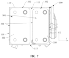
- FIG. 7 is a diagram of a partial structure of the thermal management integrated module 11 in FIG. 3 .
- a projection that is of the heat exchanger 300 and that is on the water path substrate 110 is a first projection 301.
- a distance between an edge of the first projection 301 and an edge of the water path substrate 110 is less than a first threshold.
- the distance between the edge of the first projection 301 and the edge of the water path substrate 110 is a distance perpendicular to the first direction Z. It should be noted that, that a distance between an edge of the first projection 301 and an edge of the water path substrate 110 is less than a first threshold may be understood as that the edge of the first projection 301 is adjacent to the edge of the water path substrate 110.
- the water path substrate 110 can be fully miniaturized, and a size of the water path substrate 110 is close to a size of the first projection 301 of the heat exchanger 300.
- adjacent in this embodiment means that the side that is of the water path substrate 110 and that faces the heat exchanger 300 is fully occupied by the heat exchanger 300, and no other components are disposed.
- an outer contour size of the first projection 301 may be slightly greater than a contour size of the edge of the water path substrate 110.
- the outer contour size of the first projection 301 may be slightly less than the contour size of the edge of the water path substrate 110.
- the outer contour size of the first projection 301 may alternatively be the same as the contour size of the edge of the water path substrate 110.
- the first threshold is 0. It may be understood that a value of the first threshold may change based on an actual use environment. For example, when the thermal management integrated module 11 is used in a vehicle, because a size of the thermal management integrated module 11 is small, the first threshold may be correspondingly large. In some use environments, when the size of the thermal management integrated module 11 is small, the first threshold may be small.
- the first projection 301 means a contour of an outermost side of the entire heat exchanger 300 including the two or more heat exchange components 330.
- the projection that is of the heat exchanger 300 and that is on the water path substrate 110 is a projection on the first surface 111.
- the first direction Z in the first direction Z, at least 75% of an area of the side that is of the water path substrate 110 and that faces the heat exchanger 300 directly faces the heat exchanger 300, so that the entire water path substrate 110 is subj ected to a more even force, and a large difference between forces applied to different positions is not likely to occur.
- This can effectively reduce a torsional resistance capability of the water path substrate 110, and improve torsional rigidity and structural strength of the water path substrate 110.
- a lower limit of a size of the thermal management integrated module 11 is determined by the heat exchanger 300.
- the water path substrate 110 is appropriately miniaturized, so that the thermal management integrated module 11 can be appropriately miniaturized. It should be noted that, in this implementation, the area of the side that is of the water path substrate 110 and that faces the heat exchanger 300 is an area of an outer contour
- the heat exchanger 300 includes two heat exchange components 330.
- the two heat exchange components 330 are disposed in parallel between the water path substrate 110 and the refrigerant substrate 210.
- An end face that is of each heat exchange component 330 and that faces the water path substrate 110 has a longer side 331 and a shorter side 332.
- the surface (the first surface 111) that is of the water path substrate 110 and that faces the heat exchanger 300 has a first side 115 and a second side 116. It may be understood that, that the two heat exchange components 330 are disposed in parallel between the water path substrate 110 and the refrigerant substrate 210 means that the two heat exchange components 330 are arranged in a direction perpendicular to the first direction Z instead of the first direction Z.
- the two heat exchange components 330 are arranged in a third direction Y
- the third direction Y is the same as an extension direction of the shorter side 332.
- the first side 115 corresponds to positions of the shorter sides 332 of the two heat exchange components 330.
- the second side 116 of the water path substrate 110 corresponds to a position of the longer side 331 of one of the heat exchange components 330. In this implementation, neither the first side 115 nor the second side 116 of the water path substrate 110 is too large.
- the thermal management integrated module 11 in this implementation is suitable for being mounted in a mounting environment with a length and a width that are similar to each other.
- the third direction Y is perpendicular to the first direction Z.
- FIG. 8 is a diagram of a partial structure of another structure of the thermal management integrated module 11 according to an embodiment of this application.
- a main difference between this embodiment and the embodiment in FIG. 7 is that the two heat exchange components 330 are arranged in a second direction X.
- the second direction X is the same as an extension direction of the longer side 331.
- the first side 115 corresponds to positions of the longer sides 331 of the two heat exchange components 330.
- the second side 116 of the water path substrate 110 corresponds to a position of the shorter side 332 of one of the heat exchange components 330.
- a width of the water-side component 100 in a direction of the second side 116 can be reduced.
- the thermal management integrated module 11 in this implementation is suitable for being mounted in a thin and long mounting environment.
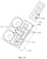
- FIG. 9 is a diagram of a partial structure of the water-side component 100 in the thermal management integrated module 11 in FIG. 3 .
- FIG. 10 is an exploded diagram of the partial structure of the water-side component 100 in FIG. 9 .
- a plurality of plumbings 117 are formed in the water path substrate 110. Some plumbings 117 are configured to communicate with the water path port 130. Some plumbings 117 are configured to communicate with an external connection port disposed on the water path substrate 110.
- the external connection port on the water path substrate 110 is set as a first external connection port 118. In some implementations, there are a plurality of first external connection ports 118.
- some of the plurality of first external connection ports 118 are configured to be connected to the water tank 12 in the thermal management system 1.
- the water tank 12 may communicate with the first external connection port 118 through a coolant hose, so that the water tank 12 and the thermal management integrated module 11 cooperate with each other in functions and are decoupled from each other in positions, to improve use performance of the water tank 12 and the thermal management integrated module 11.
- Some of the plurality of first external connection ports 118 are configured to connect to different thermal management objects 2.
- Some of the plurality of first external connection ports 118 are configured to connect to the water pump 140.
- some of the plurality of first external connection ports 118 may be further connected to a radiator in the thermal management system 1.
- the multi-port valve 150 includes a valve body 151, a valve core 152, and an actuator 153.
- the valve core 152 is disposed in the valve body 151 and can rotate relative to the valve body 151.
- the actuator 153 is configured to drive the valve core 152 to rotate relative to the valve body 151.
- Several grooves 1521 are provided on the valve core 152.
- the valve body 151 is sleeved on the valve core 152, to seal the several grooves 1521 to form several channels. Specifically, some of the several grooves 1521 communicate with each other, so that the first medium can flow in the grooves 1521 that communicate with each other.
- some grooves 1521 that communicate with each other are adjacent, and some grooves 1521 that communicate with each other are opposite.
- a plurality of water connection ports 1511 are provided on the valve body 151.
- the plurality of ports may be correspondingly connected to different channels, and the water connection ports 1511 correspondingly communicate with the plurality of plumbings 117 in the water path substrate 110.
- the multi-port valve 150 is an eight-port valve, and there are eight water connection ports 1511. In some implementations, there are nine water connection ports 1511. For ease of description, the nine water connection ports 1511 are respectively set as a port 1, a port 2, a port 3, a port 4, a port 6, a port 7, a port 8, a port 9, and a port 5.
- the port 5 is a proportionally adjustable port.
- the multi-port valve 150 may alternatively be a three-port valve, a four-port valve, or another multi-port valve 150, and there may be one or more multi-port valves 150.
- valve body 151 and the water path substrate 110 are integrated.
- FIG. 11 is a diagram of a structure of the refrigerant component 200 in the thermal management integrated module 11 in FIG. 3 .
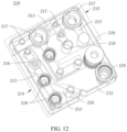
- FIG. 12 is a diagram of a structure of the refrigerant substrate 210 in the refrigerant component 200 in FIG. 11 .
- the refrigerant substrate 210 includes a second surface 211 facing the heat exchanger 300. All second functional components 220 of the refrigerant component 200 are distributed at other positions of the refrigerant substrate 210 other than the second surface 211.
- the second surface 211 is configured to correspond to the heat exchanger 300, so that a size of the second surface 211 of the refrigerant substrate 210 matches the size of the heat exchanger 300 as much as possible. This miniaturizes the refrigerant component 200.
- the second surface 211 in this embodiment is a largest surface enclosed by an outer contour of the side that is of the refrigerant substrate 210 and that faces the heat exchanger 300, and an internal hollow position also belongs to the second surface 211.
- the refrigerant substrate 210 includes an annular side panel 212 and several coolant hoses 213 fastened to an accommodation cavity enclosed by the annular side panel 212, and the several coolant hoses 213 communicate with each other to form plumbings 117 of the refrigerant substrate 210.
- the several coolant hoses 213 communicate with each other to form a first plumbing 214 and a second plumbing 215.
- the refrigerant substrate 210 further includes several first functional ports 216 that are fastened to the coolant hoses 213 and communicate with the first plumbing 214, and several second functional ports 217 that are fastened to the coolant hoses 213 and communicate with the second plumbing 215.
- all second functional components 220 of the refrigerant component 200 are mounted on a side that is of the refrigerant substrate 210 and that is away from the heat exchange component 330.
- all second functional ports 217 are located on the side that is of the refrigerant substrate 210 and that is away from the heat exchanger 300, and all second functional components 220 are correspondingly connected to the second functional ports 217.
- some second functional components 220 are expansion valves 221, some second functional components 220 are solenoid valves 222, some second functional components 220 are check valves 223, some second functional components 220 are temperature sensors, and the remaining functional components are temperature and pressure sensors 224.
- the second functional components 220 include only the expansion valve 221, the solenoid valve 222, the check valve 223, and the temperature and pressure sensor 224, and the expansion valve 221, the solenoid valve 222, the check valve 223, and the temperature and pressure sensor 224 are all small in size. Therefore, the integrated thermal management integrated module 11 has a small size. This facilitates miniaturization of the thermal management integrated module 11.
- the second functional components 220 may further include another component with a small size, for example, a gate valve, a shut-off valve, an exhaust valve, and a trap valve.
- the several first functional ports 216 are connected to a check valve 223, a temperature and pressure sensor 224, and an expansion valve 221
- the several second functional ports 217 are connected to a check valve 223, a solenoid valve 222, a temperature and pressure sensor 224, and an expansion valve 221.
- the two refrigerant ports 230 respectively communicate with the first plumbing 214 and the second plumbing 215.
- the two refrigerant ports 230 communicate with the heat exchanger 300, the first plumbing 214 and the second plumbing 215 form a path by using the heat exchanger 300.
- the heat exchanger 300 includes two heat exchange components 330.
- the two heat exchange components 330 are respectively a condensation heat exchange component 340 and an evaporation heat exchange component 350.
- the condensation heat exchange component 340 includes a condensation inlet 341 and a condensation outlet 342.
- the condensation inlet 341 communicates with the second plumbing 215.
- the condensation outlet 342 communicates with the first plumbing 214.
- the evaporation heat exchange component 350 includes an evaporation inlet 351 and an evaporation outlet 352.
- the evaporation inlet 351 communicates with the first plumbing 214.
- the evaporation outlet 352 is configured to be connected to an access of the gas-liquid separator 13 in the thermal management system 1.
- the refrigerant substrate 210 further includes a second external connection port 218.
- the evaporation outlet 352 communicates with the second external connection port 218, and then is connected to the gas-liquid separator 13 in the thermal management system 1 through the second external connection port 218.
- the second external connection port 218 may be connected to the gas-liquid separator 13 in the thermal management system 1 through a coolant hose.
- the second external connection port 218 includes a refrigerant inlet and a refrigerant outlet.
- the refrigerant inlet communicates with the second plumbing 215.
- the refrigerant outlet is connected to the gas-liquid separator 13 in the thermal management system 1 through the coolant hose.
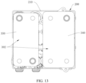
- FIG. 13 is a diagram of a partial structure of the thermal management integrated module 11 in FIG. 3 .
- a projection that is of the heat exchanger 300 and that is on the refrigerant substrate 210 is a second projection 302.
- a distance between an edge of the second projection 302 and an edge of the refrigerant substrate 210 is less than a second threshold.
- the distance between the edge of the second projection 302 and the edge of the refrigerant substrate 210 is a distance perpendicular to the first direction Z. It should be noted that, that a distance between an edge of the second projection 302 and an edge of the refrigerant substrate 210 is less than a second threshold may be understood as that the edge of the second projection 302 is adjacent to the edge of the refrigerant substrate 210.
- the refrigerant substrate 210 can be fully miniaturized, and a size of the refrigerant substrate 210 is close to a size of the second projection 302 of the heat exchanger 300. It may be understood that, “adjacent" in this embodiment means that the side that is of the refrigerant substrate 210 and that faces the heat exchanger 300 is fully occupied by the heat exchanger 300, and no other components are disposed. It may be understood that, in some implementations, an outer contour size of the second projection 302 may be slightly greater than a contour size of the edge of the refrigerant substrate 210.
- the outer contour size of the second projection 302 may be slightly less than the contour size of the edge of the refrigerant substrate 210. In some implementations, the outer contour size of the second projection 302 may alternatively be the same as the contour size of the edge of the refrigerant substrate 210. In this case, the second threshold is 0. It may be understood that a value of the second threshold may change based on an actual use environment. For example, when the thermal management integrated module 11 is used in the vehicle, because the size of the thermal management integrated module 11 is small, the second threshold may be correspondingly large. In some use environments, when the size of the thermal management integrated module 11 is small, the second threshold may be small.
- the second projection 302 means a contour of an outermost side of the entire heat exchanger 300 including the two or more heat exchange components 330.
- the first direction Z in the first direction Z, at least 75% of an area of the side that is of the refrigerant substrate 210 and that faces the heat exchanger 300 directly faces the heat exchanger 300, so that the entire refrigerant substrate 210 is subjected to a more even force, and a large difference between forces applied to different positions is not likely to occur.
- This can effectively reduce a torsional resistance capability of the refrigerant substrate 210, and improve torsional rigidity and structural strength of the refrigerant substrate 210.
- the lower limit of the size of the thermal management integrated module 11 is determined by the heat exchanger 300.
- the refrigerant substrate 210 is appropriately miniaturized, so that the thermal management integrated module 11 can be appropriately miniaturized. It should be noted that, in this implementation, the area of the side that is of the refrigerant substrate 210 and that faces the heat exchanger 300 is an area of an outer contour
- a surface that is of the water path substrate 110 and that faces the heat exchanger 300 is the first surface 111
- a surface that is of the refrigerant substrate 210 and that faces the heat exchanger 300 is the second surface 211
- an outer contour shape of the first surface 111 is the same as an outer contour shape of the second surface 211.
- both the first surface 111 and the second surface 211 are square.
- both the first surface 111 and the second surface 211 are rectangular. Because the outer contour shape of the first surface 111 is the same as the outer contour shape of the second surface 211, the entire thermal management integrated module 11 in this implementation is more structured, so that miniaturization of the thermal management integrated module 11 is facilitated, and mounting convenience can be improved.
- the first surface 111 and the second surface 211 have a same shape and size. Certainly, in some implementations, sizes of the first surface 111 and the second surface 211 may alternatively be different.
- the entire thermal management integrated module 11 is arranged in a pyramid shape or a cone shape.
- FIG. 14 is a diagram of a working principle of the thermal management system 1 according to an embodiment of this application.
- FIG. 15 shows a connection status of each water connection port 1511 when a multi-port valve 150 is in three different modes.
- the thermal management system 1 includes an evaporator, an evaporation plate heat exchanger, a condenser, a condensation plate heat exchanger, a compressor 14, a gas-liquid separator 13, a check valve 223, an expansion valve 221, a solenoid valve 222, a multi-port valve 150, a water bump 1-2, and a radiator.
- the thermal management object 2 adjusted by the thermal management system 1 is a heat source 1 and a heat source 2.
- the heat source 1 is a powertrain
- the heat source 2 is a battery.
- the multi-port valve 150 is an eight-port valve.
- the valve body 151 has nine water connection ports 1511: a port 1, a port 2, a port 3, a port 4, a port 6, a port 7, a port 8, a port 9, and a port 5.
- the port 5 is a proportionally adjustable port.
- Two ends of the evaporation plate heat exchanger are separately connected to the port 3 and the port 8, and the first medium flowing out of the port 3 flows into the port 8 through a water pump 1 and the evaporation plate heat exchanger.
- Two ends of the heat source 2 are separately connected to the port 1 and the port 6, and the first medium flowing out of the port 6 flows into the port 1 through the heat source 2.
- Two ends of the radiator are separately connected to the port 7 and the port 4, and the first medium flowing out of the port 7 flows into the port 4 through the radiator.
- One end of the heat source 1 is connected to the port 2, and the other end of the heat source 1 is connected to both the port 9 and the port 5. After flowing through the water pump 2 and the heat source 1, the first medium that flows out of the port 2 may directly flow into the port 9, or may flow into the port 5 after flowing through the condensation plate heat exchanger.
- the multi-port valve 150 has three modes.
- a mode 1 the port 1 communicates with the port 3, the port 2 communicates with the port 4, the port 9 communicates with the port 7, the port 5 communicates with the port 7, and the port 6 communicates with the port 8.
- the port 1 communicates with the port 2
- the port 3 communicates with the port 9, the port 3 communicates with the port 5,
- the port 4 communicates with the port 6, and the port 7 communicates with the port 8.
- the port 1 communicates with the port 2
- the port 3 communicates with the port 4
- the port 9 communicates with the port 6,
- the port 5 communicates with the port 6, and the port 7 communicates with the port 8.
- the actuator 153 drives the valve core 152 to rotate relative to the valve body 151, to implement conversion between the three modes.
- a first plumbing may be formed: port 3 ⁇ port 8 ⁇ port 6 ⁇ port 1 ⁇ port 3. Because the first medium flowing out of the port 3 flows into the port 8 through the water pump 1 and the evaporation plate heat exchanger, and the evaporation plate heat exchanger performs evaporation for cooling, the first medium in the first plumbing can have a low temperature, to cool the heat source 2.
- the heat source 2 is a battery, a powertrain, an electronic control module, or the like
- the thermal management system 1 in the mode 1 can be used for heat dissipation of the battery, the powertrain, and the electronic control module in summer. When cold air generated by the evaporation plate heat exchanger blows to an interior vehicle, it can also cool the interior vehicle.
- a second plumbing may be further formed: port 7 ⁇ port 4 ⁇ port 2 ⁇ port 9 (5) ⁇ port 7.
- heat dissipation may be performed on the heat source 1 through the radiator.
- the first medium heated by the condensation plate heat exchanger connected to the port 5 does not flow to the port 7.
- heat dissipation may be performed on the heat source 1 through the radiator, to cool the heat source 1.
- Different heat sources may be set as the heat source 1 based on a requirement.
- the heat source 1 may alternatively be a battery, a powertrain, an electronic control module, or the like.
- the thermal management system 1 in mode 1 can be used for cooling in summer.
- a larger proportion to which the port 5 is opened indicates a larger proportion of the first media, heated by the condensation plate heat exchanger, flowing to the second plumbing, and indicates better heating effect.
- the heat source 1 may be heated.
- first plumbing and the second plumbing may be opened and closed independently. In summer, both the first plumbing and the second plumbing may be opened, and the port 9 is completely closed, to dissipate heat for the heat source 1 and the heat source 2. In winter, the first plumbing may be closed, the second plumbing may be opened, and the port 9 may be opened.
- the condenser performs heat dissipation to heat the heat source 1. For example, the battery is heated in winter.
- a third plumbing may be formed: port 2 ⁇ port 9 (5) ⁇ port 3 ⁇ port 8 ⁇ port 7 ⁇ port 4 ⁇ port 6 ⁇ port 1 ⁇ port 2.
- the first medium cooled by the evaporation plate heat exchanger may flow to the third plumbing, and the third plumbing is connected to the heat source 1, the heat source 2, and the radiator, to perform heat dissipation on the heat source 1 and the heat source 2 for cooling.
- the thermal management system 1 in the mode 2 may be used in winter.
- the first medium heated by the condensation plate heat exchanger may flow to the third plumbing, and the third plumbing is connected to the heat source 1, the heat source 2, and the radiator, to heat the heat source 1 and the heat source 2, and adjust temperatures of the heat source 1 and the heat source 2.
- a fourth plumbing may be formed: port 2 ⁇ port 9 (5) ⁇ port 6 ⁇ port 1 ⁇ port 2.
- the first medium heated through heat dissipation of the condenser may flow to the fourth plumbing, to heat the heat source 1 and the heat source 2.
- the thermal management system 1 in the mode 3 may be used in winter.
- the port 5 is closed, heat balance of the heat source 1 and heat balance of the heat source 2 may be implemented.
- a fifth plumbing may be further formed: port 3 ⁇ port 8 ⁇ port 7 ⁇ port 4 ⁇ port 3.
- the interior vehicle may be heated through the fifth plumbing.
Landscapes
- Engineering & Computer Science (AREA)
- Physics & Mathematics (AREA)
- Thermal Sciences (AREA)
- Mechanical Engineering (AREA)
- General Engineering & Computer Science (AREA)
- Cooling Or The Like Of Electrical Apparatus (AREA)
Abstract
This application relates to a thermal management integrated module, a thermal management system, and a vehicle. The thermal management integrated module includes a water-side component 100, a refrigerant component 200, and a heat exchanger 300. The water-side component and the refrigerant component are respectively located on two opposite sides of the heat exchanger. According to this application, miniaturization of the thermal management integrated module can be implemented, and structural strength of the refrigerant substrate can be improved.
Description
- This application relates to the field of thermal management technologies, and in particular, to a thermal management integrated module, a thermal management system, and a vehicle.
- Components of a thermal management system used in an existing electric vehicle are deployed in a scattering manner. As a result, a route of a coolant hose is long. Consequently, when liquid circulates in the coolant hose, a pressure loss is severe, and cooling effect or heating effect of a loop is affected.
- In view of this, components in a thermal management system in a related technology are centrally deployed. The thermal management system in the related technology includes a water-side component, a refrigerant component, and a heat exchanger. The water-side component includes a water path substrate and a water tank. The refrigerant component includes a refrigerant substrate. The water-side component, the refrigerant component, and the heat exchanger are integrated together. The heat exchanger is integrated on a side that is of the refrigerant substrate and that is away from the water-side component. Therefore, a hole needs to be dug on the refrigerant substrate to place the heat exchanger. This causes a waste of a material of the refrigerant substrate. In addition, an extension area of the refrigerant substrate is excessively large. This is not conducive to miniaturization. In addition, because a size of the water tank is large, and there is a specific requirement for a mounting position of the water tank, a mounting environment of the thermal management system is limited, and environmental adaptability is reduced.
- Embodiments of this application provide a thermal management integrated module, a thermal management system, and a vehicle, to implement miniaturization of the thermal management integrated module and improve structural strength of a refrigerant substrate.
- According to a first aspect, an embodiment of this application provides a thermal management integrated module, including a water-side component, a refrigerant component, and a heat exchanger. The water-side component and the refrigerant component are respectively located on two opposite sides of the heat exchanger. The water-side component includes a water path substrate. A plumbing of the water path substrate is configured to accommodate a first medium. The refrigerant component includes a refrigerant substrate. A plumbing of the refrigerant substrate is configured to accommodate a second medium. The heat exchanger is located in a gap space formed by the water path substrate and the refrigerant substrate. Both the plumbing of the water path substrate and the plumbing of the refrigerant substrate communicate with a flow channel of the heat exchanger, so that the first medium exchanges heat with the second medium inside the heat exchanger. The water-side component has a first external connection port. The first external connection port is configured to connect to a water tank in a thermal management system through a coolant hose. The heat exchanger is located in the gap space formed by the water path substrate and the refrigerant substrate, to form a "sandwich" architecture, and there is no need to provide a through hole on the refrigerant substrate to place the heat exchanger. In this way, a base material for manufacturing the refrigerant substrate can be reduced, and costs can be reduced. In addition, because the through hole provided on the refrigerant substrate to place the heat exchanger is reduced, strength of the refrigerant substrate can be improved, and a size of the refrigerant substrate can be reduced. The refrigerant substrate is miniaturized, so that the strength of the refrigerant substrate can also be improved. In addition, the water tank may communicate with the first external connection port through the coolant hose, so that the water tank and the thermal management integrated module cooperate with each other in functions and are decoupled from each other in positions, to improve use performance of the water tank and the thermal management integrated module. In addition, the thermal management integrated module in this embodiment can be used in different environments, for example, can be used in both a vehicle and an energy storage system.
- In some embodiments, all functional components of the water-side component are distributed at other positions of the water path substrate other than a surface that is of the water path substrate and that faces the heat exchanger. Because the surface that is of the water path substrate and that faces the heat exchanger corresponds to the heat exchanger, all the functional components of the water-side component are distributed at the other positions of the water path substrate other than the surface that is of the water path substrate and that faces the heat exchanger. In this way, a size of the water path substrate can match a size of the heat exchanger as much as possible. This miniaturizes the water-side component.
- In some embodiments, all functional components of the refrigerant component are distributed at other positions of the refrigerant substrate other than a surface that is of the refrigerant substrate and that faces the heat exchanger. Because a second surface corresponds to the heat exchanger, all the functional components of the refrigerant component are distributed at the other positions of the refrigerant substrate other than the surface that is of the refrigerant substrate and that faces the heat exchanger. In this way, a size of the refrigerant substrate can match a size of the heat exchanger as much as possible. This miniaturizes the water-side component.
- In some embodiments, the water path substrate is provided with an inner cavity, and all the functional components of the water-side component are mounted in the inner cavity and/or on a side that is of the water path substrate and that is away from the heat exchanger. First, this can facilitate miniaturization of the thermal management integrated module. In addition, because some functional components can be disposed inside the water path substrate, the plumbing in the water path substrate can be in a 3D architecture. This can effectively use three-dimensional space, reduce a size that is of the water path substrate and that is in a direction perpendicular to a first direction, and facilitate miniaturization of the water-side component.
- In some embodiments, the water-side component, the heat exchanger, and the refrigerant component are sequentially arranged in a first direction. In the first direction, a projection that is of the heat exchanger and that is on the water path substrate is a first projection, and a projection that is of the heat exchanger and that is on the refrigerant substrate is a second projection. A distance between an edge of the first projection and an edge of the water path substrate is less than a first threshold, and/or a distance between an edge of the second projection and an edge of the refrigerant substrate is less than a second threshold. Because the edge of the first projection is adjacent to the edge of the water path substrate, the water path substrate can be fully miniaturized, and a size of the water path substrate is close to a size of the first projection of the heat exchanger. Because the edge of the second projection is adjacent to the edge of the refrigerant substrate, the refrigerant substrate can be fully miniaturized, and a size of the refrigerant substrate is close to a size of the second projection of the heat exchanger.
- In some embodiments, the surface that is of the water path substrate and that faces the heat exchanger is a first surface, the surface that is of the refrigerant substrate and that faces the heat exchanger is a second surface, and an outer contour shape of the first surface is the same as an outer contour shape of the second surface. Because the outer contour shape of the first surface is the same as the outer contour shape of the second surface, the entire thermal management integrated module in this embodiment is more structured, so that miniaturization of the thermal management integrated module is facilitated, and mounting convenience can be improved.
- In some embodiments, the water-side component, the heat exchanger, and the refrigerant component are sequentially arranged in the first direction. In the first direction, at least 75% of an area of a side that is of the water path substrate and that faces the heat exchanger directly faces the heat exchanger. In the first direction, at least 75% of an area of a side that is of the refrigerant substrate and that faces the heat exchanger directly faces the heat exchanger. A lower limit of a size of the thermal management integrated module is determined by the heat exchanger. Because the at least 75% of the area of the side that is of the water path substrate and that faces the heat exchanger directly faces the heat exchanger, the water path substrate can be appropriately miniaturized, so that the thermal management integrated module can be appropriately miniaturized. Because the at least 75% of the area of the side that is of the refrigerant substrate and that faces the heat exchanger directly faces the heat exchanger, the refrigerant substrate can be appropriately miniaturized, so that the thermal management integrated module can be appropriately miniaturized.
- In some embodiments, at least a part of the heat exchanger is in contact with the water path substrate, and at least a part of the heat exchanger is in contact with the refrigerant substrate. Because two sides that are of a heat exchange component and that are in the first direction are respectively in contact with the water path substrate and the refrigerant substrate, it can be ensured that a distance between the water path substrate and the refrigerant substrate is short, and the gap space between the water path substrate and the refrigerant substrate is only used to accommodate the heat exchanger. This helps implement a small size of the entire thermal management integrated module.
- In some embodiments, a water path port is disposed on the side that is of the water path substrate and that faces the heat exchanger, a water path connection port is disposed on the side that is of the heat exchanger and that faces the water path substrate, and the water path port is connected to the water path connection port. The water path port is located on the side that is of the water path substrate and that faces the heat exchanger, and the water path connection port is located on the side that is of the heat exchanger and that faces the water path substrate, to conveniently connect the water path substrate to the water path connection port. In addition, a length of a coolant hose that connects the water path substrate to the heat exchanger can be reduced, to facilitate miniaturization of the thermal management integrated module.
- In some embodiments, the water path port is connected to the water path connection port through a flexible coolant hose. Because the water path port is connected to the water path connection port through the flexible coolant hose, when the water path substrate deforms, hard contact does not occur on the water path port and the water path connection port, and the water path port and the water path connection port are not damaged, to avoid a leakage from the water path port and the water path connection port.
- In some embodiments, in all functional components of the water-side component, some functional components are water pumps, some functional components are temperature sensors, and the remaining functional components are multi-port valves. Because the water pump and the multi-port valve are small in size, a miniaturization design of the water-side component can be facilitated.
- In some embodiments, the water path substrate is provided with an inner cavity. The multi-port valve is located in the inner cavity. A plurality of water connection ports of the multi-port valve correspondingly communicate with a plurality of plumbings of the water path substrate. Because at least a part of the multi-port valve is disposed inside the water path substrate, the plumbing in the water path substrate can be in a 3D three-dimensional architecture. This can effectively use three-dimensional space, reduce a size that is of the water path substrate and that is in a direction perpendicular to the first direction, and facilitate miniaturization of the water-side component.
- In some embodiments, all functional components of the refrigerant component are mounted on a side that is of the refrigerant substrate and that is away from the heat exchange component. In all the functional components of the refrigerant component, some functional components are expansion valves, some functional components are solenoid valves, some functional components are check valves, some functional components are temperature sensors, and the remaining functional components are temperature and pressure sensors. Second functional components include only the expansion valve, the solenoid valve, the check valve, and the temperature and pressure sensor, and the expansion valve, the solenoid valve, the check valve, and the temperature and pressure sensor are all small in size. Therefore, the integrated thermal management integrated module has a small size. This facilitates miniaturization of the thermal management integrated module.
- In some embodiments, the water path substrate and/or the refrigerant substrate each include/includes a fastening structure. The fastening structure is configured to fasten the thermal management integrated module in a use environment. The water path substrate and/or the refrigerant substrate may be fastened, by using the fastening structure, in the use environment in which the water path substrate and/or the refrigerant substrate need/needs to be fastened, so that the thermal management integrated module in this embodiment is fastened in a use environment in which the thermal management integrated module needs to be fastened.
- In some embodiments, a first plumbing, several first functional ports communicating with the first plumbing, a second plumbing, and several second functional ports communicating with the second plumbing are formed on the refrigerant substrate. The several first functional ports are connected to the check valve, the temperature and pressure sensor, and the expansion valve. The several second functional ports are connected to the check valve, the solenoid valve, the temperature and pressure sensor, and the expansion valve.
- In some embodiments, the heat exchanger includes a condensation heat exchange component and an evaporation heat exchange component. The condensation heat exchange component includes a condensation inlet and a condensation outlet. The condensation inlet communicates with the second plumbing. The condensation outlet communicates with the first plumbing. The evaporation heat exchange component includes an evaporation inlet and an evaporation outlet. The evaporation inlet communicates with the first plumbing. The evaporation outlet is configured to be connected to an access of a gas-liquid separator in the thermal management system.
- In some embodiments, the heat exchanger includes two heat exchange components. The two heat exchange components are disposed in parallel between the water path substrate and the refrigerant substrate. An end face that is of each heat exchange component and that faces the water path substrate has a longer side and a shorter side. The surface that is of the water path substrate and that faces the heat exchanger has a first side and a second side.
- The two heat exchange components are arranged in a second direction. The second direction is the same as an extension direction of the longer side. The first side corresponds to positions of the longer sides of the two heat exchange components. The second side of the water path substrate corresponds to a position of the shorter side of one of the heat exchange components.
- In some embodiments, the heat exchanger includes two heat exchange components. The two heat exchange components are disposed in parallel between the water path substrate and the refrigerant substrate. An end face that is of each heat exchange component and that faces the water path substrate has a longer side and a shorter side. The surface that is of the water path substrate and that faces the heat exchanger has a first side and a second side. In this embodiment, a width of the water-side component in a direction of the second side can be reduced. The thermal management integrated module in this implementation is suitable for being mounted in a thin and long mounting environment.
- The two heat exchange components are arranged in a third direction. The third direction is the same as an extension direction of the shorter side. The first side corresponds to positions of the shorter sides of the two heat exchange components. The second side of the water path substrate corresponds to a position of the longer side of one of the heat exchange components. In this embodiment, neither the first side nor the second side of the water path substrate is too large. The thermal management integrated module in this implementation is suitable for being mounted in a mounting environment with a length and a width that are similar to each other.
- In some embodiments, the refrigerant component includes a second external connection port. The second external connection port is configured to be connected to a gas-liquid separator in the thermal management system through a coolant hose. The second external connection port is configured to be connected to the gas-liquid separator in the thermal management system through the coolant hose, so that a position of the thermal management integrated module in this embodiment can be decoupled from a position of the gas-liquid separator. This helps improve mounting environment adaptability of the gas-liquid separator and the thermal management integrated module, miniaturize the thermal management integrated module.
- According to a second aspect, this application provides a thermal management system, including a water tank, a gas-liquid separator, and the thermal management integrated module according to any implementation of the first aspect. The thermal management integrated module is connected to the water tank and the gas-liquid separator through coolant hoses.
- According to a third aspect, this application provides a vehicle, including a battery, a powertrain, and the foregoing thermal management system. The thermal management system is configured to perform thermal management on the battery and the powertrain.
- According to a fourth aspect, this application provides an energy storage system, including an energy storage battery and the foregoing thermal management system. The thermal management system is configured to perform thermal management on the energy storage battery.
- To describe the technical solutions in embodiments of the present invention or in the conventional technology more clearly, the following briefly introduces the accompanying drawings for describing embodiments or the conventional technology.
-
FIG. 1a is a diagram of a structure of a vehicle according to an embodiment of this application; - FIG. lb is an operating block diagram of a thermal management system of a vehicle according to an embodiment of this application;
-
FIG. 2 is an operating block diagram of a thermal management system of an energy storage system according to an embodiment of this application; -
FIG. 3 is a diagram of a structure of a thermal management integrated module according to an embodiment of this application; -
FIG. 4 is an exploded diagram of the thermal management integrated module inFIG. 3 ; -
FIG. 5 is a diagram of a structure of a water-side component in the thermal management integrated module inFIG. 3 ; -
FIG. 6 is a diagram of a structure of the water-side component inFIG. 5 from another perspective; -
FIG. 7 is a diagram of a partial structure of the thermal management integrated module inFIG. 3 ; -
FIG. 8 is a diagram of a partial structure of another structure of a thermal management integrated module according to an embodiment of this application; -
FIG. 9 is a diagram of a partial structure of the water-side component in the thermal management integrated module inFIG. 3 ; -
FIG. 10 is an exploded diagram of the partial structure of the water-side component inFIG. 9 ; -
FIG. 11 is a diagram of a structure of a refrigerant component in the thermal management integrated module inFIG. 3 ; -
FIG. 12 is a diagram of a structure of a refrigerant substrate in the refrigerant component inFIG. 11 ; -
FIG. 13 is a diagram of a partial structure of the thermal management integrated module inFIG. 3 ; -
FIG. 14 is a diagram of a working principle of a thermal management system according to an embodiment of this application; and -
FIG. 15 shows a connection status of each water connection port when a multi-port valve is in three different modes. - Z: first direction; X: second direction; Y: third direction; 1000: vehicle; 1: thermal management system; 11: thermal management integrated module; 12: water tank; 13: gas-liquid separator; 14: compressor; 2: thermal management object; 100: water-side component; 110: water path substrate; 111: first surface; 112: upper surface; 1121: first plane; 1122: second plane; 1123: third plane; 113: side surface; 115: first side; 116: second side; 117: plumbing; 118: first external connection port; 120: first functional component; 130: water path port; 140: water pump; 150: multi-port valve; 1501: inner cavity; 151: valve body; 1511: water connection port; 152: valve core; 1521: groove; 153: actuator; 200: refrigerant component; 210: refrigerant substrate; 211: second surface; 212: annular side panel; 213: coolant hose; 214: first plumbing; 215: second plumbing; 216: first functional port; 217: second functional port; 218: second external connection port; 220: second functional component; 221: expansion valve; 222: solenoid valve; 223: check valve; 224: temperature and pressure sensor; 230: refrigerant port; 300: heat exchanger; 301: first projection; 302: second projection; 310: water path connection port; 320: refrigerant connection port; 330: heat exchange component; 331: longer side; 332: shorter side; 340: condensation heat exchange component; 341: condensation inlet; 342: condensation outlet; 350: evaporation heat exchange component; 351: evaporation inlet; 352: evaporation outlet; and 400: fastening structure.
- The following first explains some terms in embodiments of this application.
- In this specification, claims, and accompanying drawings of embodiments of this application, terms "first", "second", "third", "fourth", and the like are intended to distinguish similar objects but do not need to be used to describe a specific order or sequence. It should be understood that the data used in such a way is interchangeable in appropriate circumstances, so that embodiments of this application described herein can be implemented in orders except the order illustrated or described herein. In addition, terms "include", "contain", and any variant thereof are intended to cover a non-exclusive inclusion. For example, a process, method, system, product, or device that includes a list of steps or units is not necessarily limited to those steps or units that are expressly listed, but may include other steps or units that are not expressly listed or are inherent to the process, method, product, or device.
- In this specification, terms such as "perpendicular" and "parallel" are explained.
- Perpendicularity: Perpendicularity defined in this application is not limited to an absolute perpendicular intersection (an included angle is 90 degrees) relationship, a non-absolute perpendicular intersection relationship caused by factors such as an assembly tolerance, a design tolerance, and a structural flatness is allowed, and an error within a small angle range is allowed. For example, a relationship within an assembly angle range of 80 degrees to 100 degrees may be understood as the perpendicular relationship.
- Parallelism: Parallelism defined in this application is not limited to absolute parallelism. Parallel defined herein may be understood as basic parallelism, and non-absolute parallelism caused by factors such as an assembly tolerance, a design tolerance, and a structural flatness is allowed. The factors may cause a case in which a sliding cooperation part and a first door plate are not absolutely parallel, but this application also defines, as parallelism, the case in which the sliding cooperation part and the first door plate are not absolutely parallel.
- It should be noted that the accompanying drawings in the following are diagrams, and specific shapes in the accompanying drawings are not specific shapes to be protected in this application.
- An embodiment of this application provides a thermal management system. The thermal management system in this embodiment of this application is applicable to the vehicle-mounted and the energy storage field.
- For example, the thermal management system in this embodiment of this application may be used in an electric vehicle in the vehicle-mounted, and the electric vehicle is a transportation means driven by an electric power module . The electric power module may include, for example, a power distribution unit (PDU), a microcontroller unit (MCU), a mapped diagnostic context (MDC), and a motor.
- For another example, the thermal management system in embodiments of this application may be used in a photovoltaic system, a wind power system, and the like in the energy storage field.
-
FIG. 1a is a diagram of a structure of avehicle 1000 according to an embodiment of this application. FIG. lb is an operating block diagram of athermal management system 1 of thevehicle 1000 according to an embodiment of this application. - Refer to FIG. la and FIG. lb. An embodiment of this application further provides the
vehicle 1000. Thevehicle 1000 includes thethermal management system 1 and athermal management object 2. Thethermal management system 1 is configured to perform thermal management on thethermal management object 2. It may be understood that positions of thethermal management object 2 and thethermal management system 1 in the figure are merely examples, and do not indicate that thethermal management object 2 and thethermal management system 1 are definitely at the positions shown in the figure. Thethermal management object 2 and thethermal management system 1 may alternatively be disposed at other positions. - In some implementations, the
thermal management object 2 includes one or more of a battery, a powertrain, and an electronic control module. For an electric vehicle, a battery is configured to provide most of electric energy required by thevehicle 1000. The powertrain is configured to provide power for thevehicle 1000. The powertrain may include a motor, a transmission, a transmission system, and an exhaust system. The electronic control module is an overall system including elements such as an electronic control unit (ECU), a harness, and a sensor that are of the vehicle. The electronic control module may perform refined adjustment, control, and management on an automotive engine, the transmission, braking, and security control of the vehicle, to ensure smooth traveling and stability of the vehicle in various complex driving scenarios. The electronic control module of the vehicle is an important part of the vehicle, and has high requirements for matching, debugging, maintenance, upgrading, and the like of an electronic device. - The
thermal management system 1 is configured to monitor and control a temperature of thevehicle 1000, and maintain a normal operating temperature range of each part (for example, the battery, the powertrain, the electronic control module, and an interior of the vehicle) of thevehicle 1000, to improve performance, efficiency, and comfort of thevehicle 1000. - The
thermal management system 1 includes a thermal management integratedmodule 11, awater tank 12, and a gas-liquid separator 13. - The
water tank 12 is configured to provide circulated water for the thermal management integratedmodule 11. Because thewater tank 12 is independent of the thermal management integratedmodule 11 and is connected to the thermal management integratedmodule 11 through a coolant hose, a position of thewater tank 12 can be decoupled from a position of the thermal management integratedmodule 11. For example, thewater tank 12 is placed at a higher position, and the thermal management integratedmodule 11 is placed at a lower position than that of thewater tank 12. This can improve use performance of thewater tank 12 and the thermal management integratedmodule 11, and further enable the thermal management integratedmodule 11 in this embodiment to be adapted to different environments, for example, the thermal management integratedmodule 11 can be used in both a vehicle and an energy storage system. In addition, thewater tank 12 and the thermal management integratedmodule 11 are separately and independently disposed, so that the thermal management integratedmodule 11 is not affected by thewater tank 12 with a large size. This facilitates miniaturization of the thermal management integratedmodule 11. - Similarly, a component with a large volume like the gas-
liquid separator 13 may also be independent of the thermal management integratedmodule 11, and is connected to the thermal management integratedmodule 11 through a coolant hose, to facilitate miniaturization of the thermal management integratedmodule 11. - In some implementations, a
compressor 14 in thethermal management system 1 may also be disposed independently of the thermal management integratedmodule 11. Certainly, in some implementations, thecompressor 14 may alternatively be integrated into the thermal management integratedmodule 11. -
FIG. 2 is an operating block diagram of athermal management system 1 of an energy storage system according to an embodiment of this application. - Refer to
FIG. 2 . The energy storage system includes thethermal management system 1 and thethermal management object 2. Thethermal management system 1 includes a thermal management integratedmodule 11, awater tank 12, and a gas-liquid separator 13. For the thermal management integratedmodule 11, thewater tank 12, and the gas-liquid separator 13, refer to the embodiment in FIG. lb. Details are not described herein again. Thethermal management object 2 in this embodiment is an energy storage battery, a power control system (PCS), a DC-DC converter, and the like. -
FIG. 3 is a diagram of a structure of a thermal management integratedmodule 11 according to an embodiment of this application.FIG. 4 is an exploded diagram of the thermal management integratedmodule 11 inFIG. 3 . The thermal management integratedmodule 11 in this embodiment may be used in thethermal management systems 1 in embodiments in FIG. lb andFIG. 2 , or may be used in anotherthermal management system 1, for example,thermal management systems 1 in the electronic and medical fields. - Refer to
FIG. 3 andFIG. 4 . The thermal management integratedmodule 11 includes a water-side component 100, arefrigerant component 200, and aheat exchanger 300. - The water-
side component 100 in this embodiment is mainly configured to adjust and control flowing of a first medium in the system, to ensure normal operation of a device and temperature control. For example, the first medium in the water-side component 100 may flow to positions such as a battery, a powertrain, and a control unit, to implement temperature control and adjustment on the battery, the powertrain, the control unit, and the like. - The
refrigerant component 200 in this embodiment is mainly configured to control a refrigerant to circulate in the system, to implement temperature adjustment through heat absorption and heat release. - A main function of the
heat exchanger 300 in this embodiment is to implement heat exchange. For example, in some implementations, theheat exchanger 300 may be a condenser In some implementations, theheat exchanger 300 may alternatively be an evaporator. In some implementations, theheat exchanger 300 may alternatively include both a condenser and an evaporator. - The water-
side component 100 and therefrigerant component 200 are separately connected to theheat exchanger 300, so that heat exchange between the first medium (for example, water) flowing from the water-side component 100 to theheat exchanger 300 and a second medium (for example, a refrigerant) flowing from therefrigerant component 200 to theheat exchanger 300 is implemented by using theheat exchanger 300. - The water-
side component 100 and therefrigerant component 200 are respectively located on two opposite sides of theheat exchanger 300, so that the water-side component 100, therefrigerant component 200, and theheat exchanger 300 are disposed in a "sandwich" architecture. In comparison with a solution in which aheat exchanger 300 is integrated on a side that is of arefrigerant component 200 and that is away from a water-side component 100, in this application, a size of therefrigerant component 200 can be reduced, and connection stability of functional components of therefrigerant component 200 can further be improved. - In some embodiments, the water-
side component 100 includes awater path substrate 110 and several functional components located on thewater path substrate 110. For ease of description, the functional components of the water-side component 100 are a firstfunctional component 120. Therefrigerant component 200 includes arefrigerant substrate 210 and several functional components located on therefrigerant substrate 210. For ease of description, the functional component of therefrigerant components 200 are a secondfunctional component 220. Theheat exchanger 300 is located in a gap space formed by thewater path substrate 110 and therefrigerant substrate 210, to form the "sandwich" architecture. This can facilitate miniaturization of therefrigerant substrate 210, save a material of therefrigerant substrate 210, and improve strength of therefrigerant substrate 210. - In some implementations, the
water path substrate 110 directly faces therefrigerant substrate 210 in a first direction Z. The first direction Z is also a direction in which the water-side component 100, theheat exchanger 300, and therefrigerant component 200 are sequentially arranged. In comparison with a solution in which theheat exchanger 300 is fastened to a side that is of therefrigerant substrate 210 and that is away from thewater path substrate 110, in this embodiment of this application, therefrigerant substrate 210 does not need to be provided with a through hole for placing theheat exchanger 300, to save a base material for manufacturing therefrigerant substrate 210, and reduce costs. In addition, because therefrigerant substrate 210 is not provided with a through hole for placing theheat exchanger 300, strength of therefrigerant substrate 210 is enhanced, and a size of therefrigerant substrate 210 is reduced. Therefrigerant substrate 210 is miniaturized, so that the strength of therefrigerant substrate 210 can also be improved. - In some implementations, a
water path port 130 is disposed on a side that is of thewater path substrate 110 and that faces theheat exchanger 300, a waterpath connection port 310 is disposed on a side that is of theheat exchanger 300 and that faces theheat exchanger 300, and thewater path substrate 110 is connected to the waterpath connection port 310 of theheat exchanger 300 through thewater path port 130. Thewater path port 130 is located on the side that is of thewater path substrate 110 and that faces theheat exchanger 300, and the waterpath connection port 310 is located on the side that is of theheat exchanger 300 and that faces thewater path substrate 110, to conveniently connect thewater path substrate 110 to the waterpath connection port 310. In addition, a length of acoolant hose 213 that connects thewater path substrate 110 to theheat exchanger 300 can be reduced, to facilitate miniaturization of the thermal management integratedmodule 11. - In some implementations, the
water path port 130 is directly connected to the waterpath connection port 310, and thewater path substrate 110 communicates with theheat exchanger 300 through thewater path port 130 and the waterpath connection port 310, or thewater path substrate 110 may be fastened to theheat exchanger 300 through thewater path port 130 and the waterpath connection port 310. - In some implementations, the
water path port 130 is connected to the waterpath connection port 310 through a flexible coolant hose (not shown in the figure). Because thewater path port 130 is connected to the waterpath connection port 310 through the flexible coolant hose, when thewater path substrate 110 deforms, hard contact does not occur on thewater path port 130 and the waterpath connection port 310, and thewater path port 130 and the waterpath connection port 310 are not damaged, to avoid a leakage from thewater path port 130 and the waterpath connection port 310. - It may be understood that, in this embodiment of this application, the water-
side component 100 and theheat exchanger 300 may be detached from each other and may be detachable, and may be connected through the flexible coolant hose after being detached. The water-side component 100 and theheat exchanger 300 may be connected through the flexible coolant hose after being detached. A detachable connection structure between the water-side component 100 and theheat exchanger 300 can enable the thermal management integratedmodule 11 provided in this embodiment of this application to more flexibly match different use scenarios. - In some implementations, the
water path port 130 and thewater path substrate 110 are integrated. In some implementations, thewater path port 130 and thewater path substrate 110 are spliced. - In some implementations, the water
path connection port 310 and a housing of theheat exchanger 300 are integrated. In some implementations, the waterpath connection port 310 and theheat exchanger 300 are spliced. - In some implementations, a
refrigerant port 230 is disposed on a side that is of therefrigerant substrate 210 and that faces theheat exchanger 300, arefrigerant connection port 320 is disposed on a side that is of theheat exchanger 300 and that faces therefrigerant substrate 210, and therefrigerant substrate 210 is connected to therefrigerant connection port 320 of theheat exchanger 300 through therefrigerant port 230. Therefrigerant port 230 is located on the side that is of therefrigerant substrate 210 and that faces theheat exchanger 300, and therefrigerant connection port 320 is located on the side that is of theheat exchanger 300 and that faces therefrigerant substrate 210, to conveniently connect therefrigerant substrate 210 to therefrigerant connection port 320. In addition, the length of thecoolant hose 213 that connects therefrigerant substrate 210 to theheat exchanger 300 can be reduced, to facilitate miniaturization of the thermal management integratedmodule 11. - In some implementations, the
refrigerant port 230 is directly connected to therefrigerant connection port 320, and therefrigerant substrate 210 communicates with theheat exchanger 300 through therefrigerant port 230 and therefrigerant connection port 320, or therefrigerant substrate 210 may be fastened toheat exchanger 300 through therefrigerant port 230 and therefrigerant connection port 320. - In some implementations, the
refrigerant port 230 is connected to therefrigerant connection port 320 through a flexible coolant hose. Because therefrigerant port 230 is connected to therefrigerant connection port 320 through the flexible coolant hose, when therefrigerant substrate 210 deforms, hard contact does not occur on therefrigerant port 230 and therefrigerant connection port 320, and therefrigerant port 230 and therefrigerant connection port 320 are not damaged, to avoid a leakage from therefrigerant port 230 and therefrigerant connection port 320. - In some implementations, the
refrigerant port 230 and therefrigerant connection port 320 may alternatively be made of a flexible material. Therefrigerant port 230 communicates with a plumbing in therefrigerant substrate 210. Therefrigerant connection port 320 communicates with a plumbing in theheat exchanger 300. Certainly, in some other implementations, therefrigerant port 230 and therefrigerant connection port 320 may alternatively be made of a rigid material. - In some implementations, the
refrigerant port 230 and therefrigerant substrate 210 are integrated. In some implementations, therefrigerant port 230 and therefrigerant substrate 210 are spliced. - In some implementations, the
refrigerant connection port 320 and the housing of theheat exchanger 300 are integrated. In some implementations, therefrigerant connection port 320 and theheat exchanger 300 are spliced. - In some implementations, at least a part of the
heat exchanger 300 is in contact with thewater path substrate 110, and at least a part of theheat exchanger 300 is in contact with therefrigerant substrate 210. Because two sides that are of aheat exchange component 330 and that are in the first direction Z are respectively in contact with thewater path substrate 110 and therefrigerant substrate 210, it can be ensured that a distance between thewater path substrate 110 and therefrigerant substrate 210 is short, and the gap space between thewater path substrate 110 and therefrigerant substrate 210 is only used to accommodate theheat exchanger 300. This helps implement a small size of the entire thermal management integratedmodule 11. - It may be understood that, in some implementations, the
heat exchanger 300 is at least partially in contact with therefrigerant substrate 210, or theheat exchanger 300 is at least partially in contact with thewater path substrate 110. - It may be understood that, in this embodiment of this application, the
refrigerant component 200 and theheat exchanger 300 may be detached from each other and may be detachable, and may be connected through the flexible coolant hose after being detached. A detachable connection structure between therefrigerant component 200 and theheat exchanger 300 can enable the thermal management integratedmodule 11 provided in this embodiment of this application to more flexibly match different use scenarios. - In some implementations, the
water path substrate 110 and/or therefrigerant substrate 210 each include/includes afastening structure 400. Thefastening structure 400 is configured to fasten the thermal management integratedmodule 11 in a use environment. Thewater path substrate 110 and/or therefrigerant substrate 210 may be fastened, by using thefastening structure 400, in the use environment in which thewater path substrate 110 and/or therefrigerant substrate 210 need/needs to be fastened, so that the thermal management integratedmodule 11 in this embodiment is fastened in a use environment in which the heat management integratedmodule 11 needs to be fastened. - In some implementations, the
fastening structure 400 is a fastening through hole with which thewater path substrate 110 and/or therefrigerant substrate 210 are/is provided. - In some implementations, a side face of the
water path substrate 110 and/or a side face of therefrigerant substrate 210 is provided with the fastening through hole, and the side face of thewater path substrate 110 and/or the side face of therefrigerant substrate 210 is a face adjacent to a face that faces theheat exchanger 300, so that interference in integration of the functional component and theheat exchanger 300 is not occurred. - It may be understood that, in some other implementations, the
water path substrate 110 and/or therefrigerant substrate 210 may alternatively be fastened, by using theheat exchanger 300, at a position at which thewater path substrate 110 and/or therefrigerant substrate 210 need/needs to be fastened. -
FIG. 5 is a diagram of a structure of the water-side component 100 in the thermal management integratedmodule 11 inFIG. 3 .FIG. 6 is a diagram of a structure of the water-side component 100 inFIG. 5 from another perspective. - Refer to
FIG. 5 andFIG. 6 . In some embodiments, thewater path substrate 110 includes afirst surface 111 facing theheat exchanger 300, and all firstfunctional components 120 of the water-side component 100 are distributed at other positions of thewater path substrate 110 other than thefirst surface 111. Thefirst surface 111 corresponds to theheat exchanger 300, so that a size of thefirst surface 111 of thewater path substrate 110 matches a size of theheat exchanger 300 as much as possible. This miniaturizes the water-side component 100. - In some implementations, the
first surface 111 is a plane. It may be understood that a curved surface with a small radian also belongs to the plane in this implementation. It may be understood that, in some other implementations, thefirst surface 111 may alternatively be a curved surface. - In some implementations, the
water path substrate 110 further includes an upper surface 112 away from theheat exchanger 300 and aside surface 113 configured to connect thefirst surface 111 to the upper surface 112. It may be understood that, in this implementation, words such as "upper" and "side" do not limit orientations, and are similar to words such as "first" and "second" for distinguishing names. - In some implementations, the upper surface 112 is a plane, the
water path substrate 110 is a sheet-shaped plate, and all firstfunctional components 120 are disposed on the upper surface 112. - In some implementations, the upper surface 112 includes a
first plane 1121, asecond plane 1122, and athird plane 1123 that connects thefirst plane 1121 to thesecond plane 1122. Thefirst plane 1121 and thesecond plane 1122 are parallel and do not overlap in the first direction Z. Thethird plane 1123 is perpendicular to thefirst plane 1121. In this implementation, thickness of a part corresponding to thefirst plane 1121 of thewater path substrate 110 is less than thickness of a part corresponding to thesecond plane 1122 of thewater path substrate 110, and thewater path substrate 110 has an inner cavity 1501 (as shown inFIG. 9 below). All firstfunctional components 120 are disposed on the upper surface 112 and/or theinner cavity 1501. - In some implementations, in all first
functional components 120, some firstfunctional components 120 arewater pumps 140, some firstfunctional components 120 are temperature sensors, and the remaining firstfunctional components 120 aremulti-port valves 150. Because thewater pump 140 and themulti-port valve 150 are small in size, a miniaturization design of the water-side component 100 can be facilitated. - The
water pump 140 is distributed on thefirst plane 1121, and at least a part of themulti-port valve 150 is disposed at a position that is in theinner cavity 1501 and that corresponds to thesecond plane 1122. Because at least a part of themulti-port valve 150 is disposed inside thewater path substrate 110, the plumbing in thewater path substrate 110 can be in a 3D three-dimensional architecture. This can effectively use three-dimensional space, reduce a size that is of thewater path substrate 110 and that is in a direction perpendicular to the first direction Z, and facilitate miniaturization of the water-side component 100. - It may be understood that, in some other implementations, the first
functional components 120 may further include another component, for example, may further integrate a temperature sensor, a water level switch, awater tank 12, a controller of thewater pump 140, a valve of thewater pump 140, a pulser, or an overflow valve. -
FIG. 7 is a diagram of a partial structure of the thermal management integratedmodule 11 inFIG. 3 . - Refer to
FIG. 7 . In the first direction Z, a projection that is of theheat exchanger 300 and that is on thewater path substrate 110 is afirst projection 301. A distance between an edge of thefirst projection 301 and an edge of thewater path substrate 110 is less than a first threshold. Specifically, the distance between the edge of thefirst projection 301 and the edge of thewater path substrate 110 is a distance perpendicular to the first direction Z. It should be noted that, that a distance between an edge of thefirst projection 301 and an edge of thewater path substrate 110 is less than a first threshold may be understood as that the edge of thefirst projection 301 is adjacent to the edge of thewater path substrate 110. Because the edge of thefirst projection 301 is adjacent to the edge of thewater path substrate 110, thewater path substrate 110 can be fully miniaturized, and a size of thewater path substrate 110 is close to a size of thefirst projection 301 of theheat exchanger 300. It may be understood that, "adjacent" in this embodiment means that the side that is of thewater path substrate 110 and that faces theheat exchanger 300 is fully occupied by theheat exchanger 300, and no other components are disposed. It may be understood that, in some implementations, an outer contour size of thefirst projection 301 may be slightly greater than a contour size of the edge of thewater path substrate 110. In some implementations, the outer contour size of thefirst projection 301 may be slightly less than the contour size of the edge of thewater path substrate 110. In some implementations, the outer contour size of thefirst projection 301 may alternatively be the same as the contour size of the edge of thewater path substrate 110. In this case, the first threshold is 0. It may be understood that a value of the first threshold may change based on an actual use environment. For example, when the thermal management integratedmodule 11 is used in a vehicle, because a size of the thermal management integratedmodule 11 is small, the first threshold may be correspondingly large. In some use environments, when the size of the thermal management integratedmodule 11 is small, the first threshold may be small. - It may be understood that, when the
heat exchanger 300 includes two or moreheat exchange components 330, thefirst projection 301 means a contour of an outermost side of theentire heat exchanger 300 including the two or moreheat exchange components 330. - In some implementations, the projection that is of the
heat exchanger 300 and that is on thewater path substrate 110 is a projection on thefirst surface 111. - In some implementations, in the first direction Z, at least 75% of an area of the side that is of the
water path substrate 110 and that faces theheat exchanger 300 directly faces theheat exchanger 300, so that the entirewater path substrate 110 is subj ected to a more even force, and a large difference between forces applied to different positions is not likely to occur. This can effectively reduce a torsional resistance capability of thewater path substrate 110, and improve torsional rigidity and structural strength of thewater path substrate 110. In addition, a lower limit of a size of the thermal management integratedmodule 11 is determined by theheat exchanger 300. Because the at least 75% of the area of the side that is of thewater path substrate 110 and that faces theheat exchanger 300 directly faces theheat exchanger 300, thewater path substrate 110 is appropriately miniaturized, so that the thermal management integratedmodule 11 can be appropriately miniaturized. It should be noted that, in this implementation, the area of the side that is of thewater path substrate 110 and that faces theheat exchanger 300 is an area of an outer contour - In some implementations, the
heat exchanger 300 includes twoheat exchange components 330. The twoheat exchange components 330 are disposed in parallel between thewater path substrate 110 and therefrigerant substrate 210. An end face that is of eachheat exchange component 330 and that faces thewater path substrate 110 has alonger side 331 and ashorter side 332. The surface (the first surface 111) that is of thewater path substrate 110 and that faces theheat exchanger 300 has afirst side 115 and asecond side 116. It may be understood that, that the twoheat exchange components 330 are disposed in parallel between thewater path substrate 110 and therefrigerant substrate 210 means that the twoheat exchange components 330 are arranged in a direction perpendicular to the first direction Z instead of the first direction Z. - The two
heat exchange components 330 are arranged in a third direction Y The third direction Y is the same as an extension direction of theshorter side 332. Thefirst side 115 corresponds to positions of theshorter sides 332 of the twoheat exchange components 330. Thesecond side 116 of thewater path substrate 110 corresponds to a position of thelonger side 331 of one of theheat exchange components 330. In this implementation, neither thefirst side 115 nor thesecond side 116 of thewater path substrate 110 is too large. The thermal management integratedmodule 11 in this implementation is suitable for being mounted in a mounting environment with a length and a width that are similar to each other. - In some implementations, the third direction Y is perpendicular to the first direction Z.
-
FIG. 8 is a diagram of a partial structure of another structure of the thermal management integratedmodule 11 according to an embodiment of this application. A main difference between this embodiment and the embodiment inFIG. 7 is that the twoheat exchange components 330 are arranged in a second direction X. The second direction X is the same as an extension direction of thelonger side 331. Thefirst side 115 corresponds to positions of thelonger sides 331 of the twoheat exchange components 330. Thesecond side 116 of thewater path substrate 110 corresponds to a position of theshorter side 332 of one of theheat exchange components 330. In this implementation, a width of the water-side component 100 in a direction of thesecond side 116 can be reduced. The thermal management integratedmodule 11 in this implementation is suitable for being mounted in a thin and long mounting environment. For thefirst side 115, thesecond side 116, thelonger side 331, theshorter side 332, and the like, refer to the embodiment inFIG. 7 . Details are not described herein again. -
FIG. 9 is a diagram of a partial structure of the water-side component 100 in the thermal management integratedmodule 11 inFIG. 3 .FIG. 10 is an exploded diagram of the partial structure of the water-side component 100 inFIG. 9 . - Refer to
FIG. 9 andFIG. 10 . In some embodiments, a plurality ofplumbings 117 are formed in thewater path substrate 110. Someplumbings 117 are configured to communicate with thewater path port 130. Someplumbings 117 are configured to communicate with an external connection port disposed on thewater path substrate 110. For ease of description, the external connection port on thewater path substrate 110 is set as a firstexternal connection port 118. In some implementations, there are a plurality of firstexternal connection ports 118. - In some implementations, some of the plurality of first
external connection ports 118 are configured to be connected to thewater tank 12 in thethermal management system 1. Specifically, thewater tank 12 may communicate with the firstexternal connection port 118 through a coolant hose, so that thewater tank 12 and the thermal management integratedmodule 11 cooperate with each other in functions and are decoupled from each other in positions, to improve use performance of thewater tank 12 and the thermal management integratedmodule 11. Some of the plurality of firstexternal connection ports 118 are configured to connect to different thermal management objects 2. Some of the plurality of firstexternal connection ports 118 are configured to connect to thewater pump 140. - In some implementations, some of the plurality of first
external connection ports 118 may be further connected to a radiator in thethermal management system 1. - In some implementations, the
multi-port valve 150 includes avalve body 151, avalve core 152, and anactuator 153. Thevalve core 152 is disposed in thevalve body 151 and can rotate relative to thevalve body 151. Theactuator 153 is configured to drive thevalve core 152 to rotate relative to thevalve body 151. -
Several grooves 1521 are provided on thevalve core 152. Thevalve body 151 is sleeved on thevalve core 152, to seal theseveral grooves 1521 to form several channels. Specifically, some of theseveral grooves 1521 communicate with each other, so that the first medium can flow in thegrooves 1521 that communicate with each other. - In some implementations, some
grooves 1521 that communicate with each other are adjacent, and somegrooves 1521 that communicate with each other are opposite. - A plurality of
water connection ports 1511 are provided on thevalve body 151. When theactuator 153 drives thevalve core 152 to rotate at different positions, the plurality of ports may be correspondingly connected to different channels, and thewater connection ports 1511 correspondingly communicate with the plurality ofplumbings 117 in thewater path substrate 110. - In some implementations, the
multi-port valve 150 is an eight-port valve, and there are eightwater connection ports 1511. In some implementations, there are ninewater connection ports 1511. For ease of description, the ninewater connection ports 1511 are respectively set as aport 1, aport 2, aport 3, aport 4, aport 6, aport 7, aport 8, aport 9, and aport 5. Theport 5 is a proportionally adjustable port. Certainly, in some implementations, themulti-port valve 150 may alternatively be a three-port valve, a four-port valve, or anothermulti-port valve 150, and there may be one or moremulti-port valves 150. - In some implementations, the
valve body 151 and thewater path substrate 110 are integrated. -
FIG. 11 is a diagram of a structure of therefrigerant component 200 in the thermal management integratedmodule 11 inFIG. 3 .FIG. 12 is a diagram of a structure of therefrigerant substrate 210 in therefrigerant component 200 inFIG. 11 . - Refer to
FIG. 11 andFIG. 12 . In some embodiments, therefrigerant substrate 210 includes asecond surface 211 facing theheat exchanger 300. All secondfunctional components 220 of therefrigerant component 200 are distributed at other positions of therefrigerant substrate 210 other than thesecond surface 211. Thesecond surface 211 is configured to correspond to theheat exchanger 300, so that a size of thesecond surface 211 of therefrigerant substrate 210 matches the size of theheat exchanger 300 as much as possible. This miniaturizes therefrigerant component 200. It should be noted that thesecond surface 211 in this embodiment is a largest surface enclosed by an outer contour of the side that is of therefrigerant substrate 210 and that faces theheat exchanger 300, and an internal hollow position also belongs to thesecond surface 211. - In some implementations, the
refrigerant substrate 210 includes anannular side panel 212 andseveral coolant hoses 213 fastened to an accommodation cavity enclosed by theannular side panel 212, and theseveral coolant hoses 213 communicate with each other to formplumbings 117 of therefrigerant substrate 210. - In some implementations, the
several coolant hoses 213 communicate with each other to form afirst plumbing 214 and asecond plumbing 215. Therefrigerant substrate 210 further includes several firstfunctional ports 216 that are fastened to thecoolant hoses 213 and communicate with thefirst plumbing 214, and several secondfunctional ports 217 that are fastened to thecoolant hoses 213 and communicate with thesecond plumbing 215. - In some implementations, all second
functional components 220 of therefrigerant component 200 are mounted on a side that is of therefrigerant substrate 210 and that is away from theheat exchange component 330. Specifically, all secondfunctional ports 217 are located on the side that is of therefrigerant substrate 210 and that is away from theheat exchanger 300, and all secondfunctional components 220 are correspondingly connected to the secondfunctional ports 217. - In all second
functional components 220, some secondfunctional components 220 areexpansion valves 221, some secondfunctional components 220 aresolenoid valves 222, some secondfunctional components 220 arecheck valves 223, some secondfunctional components 220 are temperature sensors, and the remaining functional components are temperature andpressure sensors 224. The secondfunctional components 220 include only theexpansion valve 221, thesolenoid valve 222, thecheck valve 223, and the temperature andpressure sensor 224, and theexpansion valve 221, thesolenoid valve 222, thecheck valve 223, and the temperature andpressure sensor 224 are all small in size. Therefore, the integrated thermal management integratedmodule 11 has a small size. This facilitates miniaturization of the thermal management integratedmodule 11. - It may be understood that, in some other implementations, the second
functional components 220 may further include another component with a small size, for example, a gate valve, a shut-off valve, an exhaust valve, and a trap valve. - In some implementations, the several first
functional ports 216 are connected to acheck valve 223, a temperature andpressure sensor 224, and anexpansion valve 221, and the several secondfunctional ports 217 are connected to acheck valve 223, asolenoid valve 222, a temperature andpressure sensor 224, and anexpansion valve 221. In some implementations, there are tworefrigerant ports 230. The tworefrigerant ports 230 respectively communicate with thefirst plumbing 214 and thesecond plumbing 215. In this implementation, because the tworefrigerant ports 230 respectively communicate with thefirst plumbing 214 and thesecond plumbing 215, and the tworefrigerant ports 230 communicate with theheat exchanger 300, thefirst plumbing 214 and thesecond plumbing 215 form a path by using theheat exchanger 300. - Refer to some implementations in
FIG. 4 ,FIG. 11 , andFIG. 12 . Theheat exchanger 300 includes twoheat exchange components 330. The twoheat exchange components 330 are respectively a condensationheat exchange component 340 and an evaporationheat exchange component 350. The condensationheat exchange component 340 includes acondensation inlet 341 and acondensation outlet 342. Thecondensation inlet 341 communicates with thesecond plumbing 215. Thecondensation outlet 342 communicates with thefirst plumbing 214. The evaporationheat exchange component 350 includes anevaporation inlet 351 and anevaporation outlet 352. Theevaporation inlet 351 communicates with thefirst plumbing 214. Theevaporation outlet 352 is configured to be connected to an access of the gas-liquid separator 13 in thethermal management system 1. Specifically, therefrigerant substrate 210 further includes a secondexternal connection port 218. Theevaporation outlet 352 communicates with the secondexternal connection port 218, and then is connected to the gas-liquid separator 13 in thethermal management system 1 through the secondexternal connection port 218. Specifically, the secondexternal connection port 218 may be connected to the gas-liquid separator 13 in thethermal management system 1 through a coolant hose. - In some implementations, the second
external connection port 218 includes a refrigerant inlet and a refrigerant outlet. The refrigerant inlet communicates with thesecond plumbing 215. The refrigerant outlet is connected to the gas-liquid separator 13 in thethermal management system 1 through the coolant hose. -
FIG. 13 is a diagram of a partial structure of the thermal management integratedmodule 11 inFIG. 3 . - Refer to
FIG. 13 . In the first direction Z, a projection that is of theheat exchanger 300 and that is on therefrigerant substrate 210 is asecond projection 302. A distance between an edge of thesecond projection 302 and an edge of therefrigerant substrate 210 is less than a second threshold. Specifically, the distance between the edge of thesecond projection 302 and the edge of therefrigerant substrate 210 is a distance perpendicular to the first direction Z. It should be noted that, that a distance between an edge of thesecond projection 302 and an edge of therefrigerant substrate 210 is less than a second threshold may be understood as that the edge of thesecond projection 302 is adjacent to the edge of therefrigerant substrate 210. Because the edge of thesecond projection 302 is adjacent to the edge of therefrigerant substrate 210, therefrigerant substrate 210 can be fully miniaturized, and a size of therefrigerant substrate 210 is close to a size of thesecond projection 302 of theheat exchanger 300. It may be understood that, "adjacent" in this embodiment means that the side that is of therefrigerant substrate 210 and that faces theheat exchanger 300 is fully occupied by theheat exchanger 300, and no other components are disposed. It may be understood that, in some implementations, an outer contour size of thesecond projection 302 may be slightly greater than a contour size of the edge of therefrigerant substrate 210. In some implementations, the outer contour size of thesecond projection 302 may be slightly less than the contour size of the edge of therefrigerant substrate 210. In some implementations, the outer contour size of thesecond projection 302 may alternatively be the same as the contour size of the edge of therefrigerant substrate 210. In this case, the second threshold is 0. It may be understood that a value of the second threshold may change based on an actual use environment. For example, when the thermal management integratedmodule 11 is used in the vehicle, because the size of the thermal management integratedmodule 11 is small, the second threshold may be correspondingly large. In some use environments, when the size of the thermal management integratedmodule 11 is small, the second threshold may be small. - It may be understood that, when the
heat exchanger 300 includes two or moreheat exchange components 330, thesecond projection 302 means a contour of an outermost side of theentire heat exchanger 300 including the two or moreheat exchange components 330. - In some implementations, in the first direction Z, at least 75% of an area of the side that is of the
refrigerant substrate 210 and that faces theheat exchanger 300 directly faces theheat exchanger 300, so that the entirerefrigerant substrate 210 is subjected to a more even force, and a large difference between forces applied to different positions is not likely to occur. This can effectively reduce a torsional resistance capability of therefrigerant substrate 210, and improve torsional rigidity and structural strength of therefrigerant substrate 210. In addition, the lower limit of the size of the thermal management integratedmodule 11 is determined by theheat exchanger 300. Because the at least 75% of the area of the side that is of therefrigerant substrate 210 and that faces theheat exchanger 300 directly faces theheat exchanger 300, therefrigerant substrate 210 is appropriately miniaturized, so that the thermal management integratedmodule 11 can be appropriately miniaturized. It should be noted that, in this implementation, the area of the side that is of therefrigerant substrate 210 and that faces theheat exchanger 300 is an area of an outer contour - Refer to
FIG. 3 ,FIG. 7 , andFIG. 13 . In some implementations, a surface that is of thewater path substrate 110 and that faces theheat exchanger 300 is thefirst surface 111, a surface that is of therefrigerant substrate 210 and that faces theheat exchanger 300 is thesecond surface 211, and an outer contour shape of thefirst surface 111 is the same as an outer contour shape of thesecond surface 211. For example, in some implementations, both thefirst surface 111 and thesecond surface 211 are square. In some implementations, both thefirst surface 111 and thesecond surface 211 are rectangular. Because the outer contour shape of thefirst surface 111 is the same as the outer contour shape of thesecond surface 211, the entire thermal management integratedmodule 11 in this implementation is more structured, so that miniaturization of the thermal management integratedmodule 11 is facilitated, and mounting convenience can be improved. - In some implementations, the
first surface 111 and thesecond surface 211 have a same shape and size. Certainly, in some implementations, sizes of thefirst surface 111 and thesecond surface 211 may alternatively be different. For example, the entire thermal management integratedmodule 11 is arranged in a pyramid shape or a cone shape. -
FIG. 14 is a diagram of a working principle of thethermal management system 1 according to an embodiment of this application.FIG. 15 shows a connection status of eachwater connection port 1511 when amulti-port valve 150 is in three different modes. - Refer to
FIG. 14 . Thethermal management system 1 includes an evaporator, an evaporation plate heat exchanger, a condenser, a condensation plate heat exchanger, acompressor 14, a gas-liquid separator 13, acheck valve 223, anexpansion valve 221, asolenoid valve 222, amulti-port valve 150, a water bump 1-2, and a radiator. For the evaporator, the evaporation plate heat exchanger, the condenser, the condensation plate heat exchanger, thecompressor 14, the gas-liquid separator 13, thecheck valve 223, theexpansion valve 221, thesolenoid valve 222, themulti-port valve 150, the water bump 1-2, and the radiator, refer to the foregoing descriptions of the evaporationheat exchange component 350, the condensationheat exchange component 340, thecompressor 14, the gas-liquid separator 13, thecheck valve 223, theexpansion valve 221, thesolenoid valve 222, themulti-port valve 150, thewater pump 140, and the radiator. Details are not described herein. In this embodiment, thethermal management object 2 adjusted by thethermal management system 1 is aheat source 1 and aheat source 2. For example, theheat source 1 is a powertrain, and theheat source 2 is a battery. - The
multi-port valve 150 is an eight-port valve. Thevalve body 151 has nine water connection ports 1511: aport 1, aport 2, aport 3, aport 4, aport 6, aport 7, aport 8, aport 9, and aport 5. Theport 5 is a proportionally adjustable port. Two ends of the evaporation plate heat exchanger are separately connected to theport 3 and theport 8, and the first medium flowing out of theport 3 flows into theport 8 through awater pump 1 and the evaporation plate heat exchanger. Two ends of theheat source 2 are separately connected to theport 1 and theport 6, and the first medium flowing out of theport 6 flows into theport 1 through theheat source 2. Two ends of the radiator are separately connected to theport 7 and theport 4, and the first medium flowing out of theport 7 flows into theport 4 through the radiator. One end of theheat source 1 is connected to theport 2, and the other end of theheat source 1 is connected to both theport 9 and theport 5. After flowing through thewater pump 2 and theheat source 1, the first medium that flows out of theport 2 may directly flow into theport 9, or may flow into theport 5 after flowing through the condensation plate heat exchanger. - Refer to
FIG. 15 . In some implementations, themulti-port valve 150 has three modes. In amode 1, theport 1 communicates with theport 3, theport 2 communicates with theport 4, theport 9 communicates with theport 7, theport 5 communicates with theport 7, and theport 6 communicates with theport 8. In amode 2, theport 1 communicates with theport 2, theport 3 communicates with theport 9, theport 3 communicates with theport 5, theport 4 communicates with theport 6, and theport 7 communicates with theport 8. In amode 3, theport 1 communicates with theport 2, theport 3 communicates with theport 4, theport 9 communicates with theport 6, theport 5 communicates with theport 6, and theport 7 communicates with theport 8. Theactuator 153 drives thevalve core 152 to rotate relative to thevalve body 151, to implement conversion between the three modes. - It can be learned from the foregoing descriptions that, in the
mode 1, a first plumbing may be formed:port 3→port 8→port 6→port 1→port 3. Because the first medium flowing out of theport 3 flows into theport 8 through thewater pump 1 and the evaporation plate heat exchanger, and the evaporation plate heat exchanger performs evaporation for cooling, the first medium in the first plumbing can have a low temperature, to cool theheat source 2. When theheat source 2 is a battery, a powertrain, an electronic control module, or the like, thethermal management system 1 in themode 1 can be used for heat dissipation of the battery, the powertrain, and the electronic control module in summer. When cold air generated by the evaporation plate heat exchanger blows to an interior vehicle, it can also cool the interior vehicle. - In addition, in the
mode 1, a second plumbing may be further formed:port 7→port 4→port 2→port 9 (5)→port 7. In this case, heat dissipation may be performed on theheat source 1 through the radiator. When theport 5 is completely closed, the first medium heated by the condensation plate heat exchanger connected to theport 5 does not flow to theport 7. In this case, heat dissipation may be performed on theheat source 1 through the radiator, to cool theheat source 1. Different heat sources may be set as theheat source 1 based on a requirement. For example, theheat source 1 may alternatively be a battery, a powertrain, an electronic control module, or the like. In this case, thethermal management system 1 inmode 1 can be used for cooling in summer. When theport 5 is opened, a larger proportion to which theport 5 is opened indicates a larger proportion of the first media, heated by the condensation plate heat exchanger, flowing to the second plumbing, and indicates better heating effect. In this case, theheat source 1 may be heated. - It may be understood that the first plumbing and the second plumbing may be opened and closed independently. In summer, both the first plumbing and the second plumbing may be opened, and the
port 9 is completely closed, to dissipate heat for theheat source 1 and theheat source 2. In winter, the first plumbing may be closed, the second plumbing may be opened, and theport 9 may be opened. The condenser performs heat dissipation to heat theheat source 1. For example, the battery is heated in winter. - In the
mode 2, a third plumbing may be formed:port 2→port 9 (5)→port 3→port 8→port 7→port 4→port 6→port 1→port 2. When theport 5 is completely closed, thethermal management system 1 in themode 2 may be used in summer. The first medium cooled by the evaporation plate heat exchanger may flow to the third plumbing, and the third plumbing is connected to theheat source 1, theheat source 2, and the radiator, to perform heat dissipation on theheat source 1 and theheat source 2 for cooling. When theport 5 is opened, and the evaporation plate heat exchanger stops working, thethermal management system 1 in themode 2 may be used in winter. The first medium heated by the condensation plate heat exchanger may flow to the third plumbing, and the third plumbing is connected to theheat source 1, theheat source 2, and the radiator, to heat theheat source 1 and theheat source 2, and adjust temperatures of theheat source 1 and theheat source 2. - In the
mode 3, a fourth plumbing may be formed:port 2→port 9 (5)→port 6→port 1→port 2. When theport 5 is opened, the first medium heated through heat dissipation of the condenser may flow to the fourth plumbing, to heat theheat source 1 and theheat source 2. In this case, thethermal management system 1 in themode 3 may be used in winter. When theport 5 is closed, heat balance of theheat source 1 and heat balance of theheat source 2 may be implemented. - Similarly, in the
mode 3, a fifth plumbing may be further formed:port 3→port 8→port 7→port 4→port 3. For example, in winter, the interior vehicle may be heated through the fifth plumbing. - The foregoing descriptions are merely specific implementations of the present invention, but are not intended to limit the protection scope of the present invention. Any variation or replacement readily figured out by a person skilled in the art within the technical scope disclosed in the present invention shall fall within the protection scope of the present invention. Therefore, the protection scope of the present invention shall be subject to the protection scope of the claims.
Claims (13)
- A thermal management integrated module, comprising a water-side component, a refrigerant component, and a heat exchanger, wherein the water-side component and the refrigerant component are respectively located on two opposite sides of the heat exchanger, the water-side component comprises a water path substrate, a plumbing of the water path substrate is configured to accommodate a first medium, the refrigerant component comprises a refrigerant substrate, a plumbing of the refrigerant substrate is configured to accommodate a second medium, the heat exchanger is located in a gap space formed by the water path substrate and the refrigerant substrate, both the plumbing of the water path substrate and the plumbing of the refrigerant substrate communicate with a plumbing of the heat exchanger, so that the first medium exchanges heat with the second medium inside the heat exchanger, the water-side component has a first external connection port, and the first external connection port is configured to connect to a water tank in a thermal management system through a coolant hose.
- The thermal management integrated module according to claim 1, wherein all functional components of the water-side component are distributed at other positions of the water path substrate other than a surface that is of the water path substrate and that faces the heat exchanger; and/or
all functional components of the refrigerant component are distributed at other positions of the refrigerant substrate other than a surface that is of the refrigerant substrate and that faces the heat exchanger. - The thermal management integrated module according to claim 2, wherein the water path substrate is provided with an inner cavity, and all the functional components of the water-side component are mounted in the inner cavity and/or on a side that is of the water path substrate and that is away from the heat exchanger.
- The thermal management integrated module according to any one of claims 1 to 3, wherein the water-side component, the heat exchanger, and the refrigerant component are sequentially arranged in a first direction, and in the first direction, a projection that is of the heat exchanger and that is on the water path substrate is a first projection, and a projection that is of the heat exchanger and that is on the refrigerant substrate is a second projection; and
a distance between an edge of the first projection and an edge of the water path substrate is less than a first threshold, and/or a distance between an edge of the second projection and an edge of the refrigerant substrate is less than a second threshold. - The thermal management integrated module according to any one of claims 1 to 4, wherein the surface that is of the water path substrate and that faces the heat exchanger is a first surface, the surface that is of the refrigerant substrate and that faces the heat exchanger is a second surface, and an outer contour shape of the first surface is the same as an outer contour shape of the second surface.
- The thermal management integrated module according to any one of claims 1 to 5, wherein at least a part of the heat exchanger is in contact with the water path substrate, and at least a part of the heat exchanger is in contact with the refrigerant substrate.
- The thermal management integrated module according to claim 1, wherein some functional components of the water path substrate are multi-port valves, the water path substrate is provided with an inner cavity, the multi-port valve is located in the inner cavity, and a plurality of water connection ports of the multi-port valve correspondingly communicate with a plurality of plumbings of the water path substrate.
- The thermal management integrated module according to any one of claims 1 to 7, wherein the water path substrate and/or the refrigerant substrate each comprise/comprises a fastening structure, and the fastening structure is configured to fasten the thermal management integrated module in a use environment.
- The thermal management integrated module according to any one of claims 1 to 8, wherein the heat exchanger comprises two heat exchange components, the two heat exchange components are disposed in parallel between the water path substrate and the refrigerant substrate, an end face that is of each heat exchange component and that faces the water path substrate has a longer side and a shorter side, and the surface that is of the water path substrate and that faces the heat exchanger has a first side and a second side; and
the two heat exchange components are arranged in a second direction, the second direction is the same as an extension direction of the longer side, the first side corresponds to positions of the longer sides of the two heat exchange components, and the second side of the water path substrate corresponds to a position of the shorter side of one of the heat exchange components. - The thermal management integrated module according to any one of claims 1 to 8, wherein the heat exchanger comprises two heat exchange components, the two heat exchange components are disposed in parallel between the water path substrate and the refrigerant substrate, an end face that is of each heat exchange component and that faces the water path substrate has a longer side and a shorter side, and the surface that is of the water path substrate and that faces the heat exchanger has a first side and a second side; and
the two heat exchange components are arranged in a third direction, the third direction is the same as an extension direction of the shorter side, the first side corresponds to positions of the shorter sides of the two heat exchange components, and the second side of the water path substrate corresponds to a position of the longer side of one of the heat exchange components. - The thermal management integrated module according to any one of claims 1 to 10, wherein the refrigerant component comprises a second external connection port, and the second external connection port is configured to be connected to a gas-liquid separator in the thermal management system through a coolant hose.
- A thermal management system, comprising a water tank, a gas-liquid separator, and the thermal management integrated module according to any one of claims 1 to 11, wherein the thermal management integrated module is connected to the water tank and the gas-liquid separator through coolant hoses.
- A vehicle, comprising a battery, a powertrain, and the thermal management system according to claim 12, wherein the thermal management system is configured to perform thermal management on the battery and the powertrain.
Applications Claiming Priority (1)
| Application Number | Priority Date | Filing Date | Title |
|---|---|---|---|
| CN202311036711.XA CN117227455A (en) | 2023-08-16 | 2023-08-16 | Thermal management integrated modules, thermal management systems and vehicles |
Publications (1)
| Publication Number | Publication Date |
|---|---|
| EP4512644A1 true EP4512644A1 (en) | 2025-02-26 |
Family
ID=89083441
Family Applications (1)
| Application Number | Title | Priority Date | Filing Date |
|---|---|---|---|
| EP24193899.2A Pending EP4512644A1 (en) | 2023-08-16 | 2024-08-09 | Thermal management integrated module, thermal management system, and vehicle |
Country Status (3)
| Country | Link |
|---|---|
| US (1) | US20250058601A1 (en) |
| EP (1) | EP4512644A1 (en) |
| CN (1) | CN117227455A (en) |
Families Citing this family (1)
| Publication number | Priority date | Publication date | Assignee | Title |
|---|---|---|---|---|
| CN117565626A (en) * | 2023-12-18 | 2024-02-20 | 浙江极氪智能科技有限公司 | vehicle |
Citations (3)
| Publication number | Priority date | Publication date | Assignee | Title |
|---|---|---|---|---|
| CN113199922A (en) * | 2021-06-23 | 2021-08-03 | 曼德电子电器有限公司 | Heat exchanger combined module |
| US11440376B2 (en) * | 2017-08-04 | 2022-09-13 | Tesla, Inc. | Technologies for manifolds |
| CN116118419A (en) * | 2021-11-12 | 2023-05-16 | 浙江三花汽车零部件有限公司 | Fluid control assembly and thermal management system |
-
2023
- 2023-08-16 CN CN202311036711.XA patent/CN117227455A/en active Pending
-
2024
- 2024-08-09 EP EP24193899.2A patent/EP4512644A1/en active Pending
- 2024-08-14 US US18/804,294 patent/US20250058601A1/en active Pending
Patent Citations (3)
| Publication number | Priority date | Publication date | Assignee | Title |
|---|---|---|---|---|
| US11440376B2 (en) * | 2017-08-04 | 2022-09-13 | Tesla, Inc. | Technologies for manifolds |
| CN113199922A (en) * | 2021-06-23 | 2021-08-03 | 曼德电子电器有限公司 | Heat exchanger combined module |
| CN116118419A (en) * | 2021-11-12 | 2023-05-16 | 浙江三花汽车零部件有限公司 | Fluid control assembly and thermal management system |
Also Published As
| Publication number | Publication date |
|---|---|
| CN117227455A (en) | 2023-12-15 |
| US20250058601A1 (en) | 2025-02-20 |
Similar Documents
| Publication | Publication Date | Title |
|---|---|---|
| CN215063015U (en) | Manifold Integration Module | |
| CN216033602U (en) | Valve bank integrated module | |
| KR102276255B1 (en) | Integrated Thermal Management Valve For Vehicle | |
| EP4299344A1 (en) | Integrated valve set module for thermal management system, vehicle thermal management system, and vehicle | |
| WO2021036957A1 (en) | Thermal management system for vehicle, and thermal management method based on thermal management system | |
| CN115257302A (en) | Integrated thermal management module with ten-way valve and vehicle | |
| CN115107466B (en) | Extended range electric vehicle thermal management system, control method and extended range electric vehicle | |
| US12128730B2 (en) | Thermal management system | |
| CN114435065A (en) | heat exchange system for vehicles | |
| KR102830843B1 (en) | Automotive air conditioning system | |
| US20250058601A1 (en) | Thermal management integrated module, thermal management system, and vehicle | |
| KR102684354B1 (en) | Multi-port valve, temperature management system using the same and integrate modiule comprisinig the same | |
| US20240300300A1 (en) | Heat exchange system and vehicle | |
| CN116804520A (en) | Thermal management integrated module and thermal management system | |
| US20250115099A1 (en) | Thermal management device | |
| CN119116641B (en) | A thermal management water circuit integrated module, a vehicle thermal management system and control method | |
| EP4509742A2 (en) | Multi-port valve, water-side component, thermal management integrated system, and vehicle | |
| US20230092471A1 (en) | Plate arrangement for fluid flow | |
| US11926192B2 (en) | Refrigerant heat exchange apparatus and indirect heat pump system | |
| CN118494105A (en) | Vehicle thermal management system and vehicle | |
| CN115320328A (en) | Integrated module and thermal management system | |
| CN223283285U (en) | Thermal management integrated module | |
| CN119734562B (en) | Direct heat pump thermal management system architecture and ten-way valve structure based on ten-way valve | |
| US20250074140A1 (en) | Vehicular thermal management module | |
| CN220980393U (en) | Temperature control system, energy storage system, vehicle and multi-way valve |
Legal Events
| Date | Code | Title | Description |
|---|---|---|---|
| PUAI | Public reference made under article 153(3) epc to a published international application that has entered the european phase |
Free format text: ORIGINAL CODE: 0009012 |
|
| STAA | Information on the status of an ep patent application or granted ep patent |
Free format text: STATUS: THE APPLICATION HAS BEEN PUBLISHED |
|
| AK | Designated contracting states |
Kind code of ref document: A1 Designated state(s): AL AT BE BG CH CY CZ DE DK EE ES FI FR GB GR HR HU IE IS IT LI LT LU LV MC ME MK MT NL NO PL PT RO RS SE SI SK SM TR |
|
| STAA | Information on the status of an ep patent application or granted ep patent |
Free format text: STATUS: REQUEST FOR EXAMINATION WAS MADE |
|
| 17P | Request for examination filed |
Effective date: 20250826 |