EP4512639A1 - Pneumatic tire - Google Patents
Pneumatic tire Download PDFInfo
- Publication number
- EP4512639A1 EP4512639A1 EP24192059.4A EP24192059A EP4512639A1 EP 4512639 A1 EP4512639 A1 EP 4512639A1 EP 24192059 A EP24192059 A EP 24192059A EP 4512639 A1 EP4512639 A1 EP 4512639A1
- Authority
- EP
- European Patent Office
- Prior art keywords
- tire
- radial direction
- bead
- tire radial
- rubber
- Prior art date
- Legal status (The legal status is an assumption and is not a legal conclusion. Google has not performed a legal analysis and makes no representation as to the accuracy of the status listed.)
- Granted
Links
Images


Classifications
-
- B—PERFORMING OPERATIONS; TRANSPORTING
- B60—VEHICLES IN GENERAL
- B60C—VEHICLE TYRES; TYRE INFLATION; TYRE CHANGING; CONNECTING VALVES TO INFLATABLE ELASTIC BODIES IN GENERAL; DEVICES OR ARRANGEMENTS RELATED TO TYRES
- B60C15/00—Tyre beads, e.g. ply turn-up or overlap
- B60C15/0009—Tyre beads, e.g. ply turn-up or overlap features of the carcass terminal portion
- B60C15/0036—Tyre beads, e.g. ply turn-up or overlap features of the carcass terminal portion with high ply turn-up, i.e. folded around the bead core and terminating radially above the point of maximum section width
- B60C15/0045—Tyre beads, e.g. ply turn-up or overlap features of the carcass terminal portion with high ply turn-up, i.e. folded around the bead core and terminating radially above the point of maximum section width with ply turn-up up to the belt edges, i.e. folded around the bead core and extending to the belt edges
-
- B—PERFORMING OPERATIONS; TRANSPORTING
- B60—VEHICLES IN GENERAL
- B60C—VEHICLE TYRES; TYRE INFLATION; TYRE CHANGING; CONNECTING VALVES TO INFLATABLE ELASTIC BODIES IN GENERAL; DEVICES OR ARRANGEMENTS RELATED TO TYRES
- B60C15/00—Tyre beads, e.g. ply turn-up or overlap
- B60C15/06—Flipper strips, fillers, or chafing strips and reinforcing layers for the construction of the bead
- B60C15/0628—Flipper strips, fillers, or chafing strips and reinforcing layers for the construction of the bead comprising a bead reinforcing layer
- B60C15/0632—Flipper strips, fillers, or chafing strips and reinforcing layers for the construction of the bead comprising a bead reinforcing layer using flippers in contact with and wrapped around the bead core and, at least partially, in contact with the bead filler
-
- B—PERFORMING OPERATIONS; TRANSPORTING
- B60—VEHICLES IN GENERAL
- B60C—VEHICLE TYRES; TYRE INFLATION; TYRE CHANGING; CONNECTING VALVES TO INFLATABLE ELASTIC BODIES IN GENERAL; DEVICES OR ARRANGEMENTS RELATED TO TYRES
- B60C15/00—Tyre beads, e.g. ply turn-up or overlap
- B60C15/0009—Tyre beads, e.g. ply turn-up or overlap features of the carcass terminal portion
-
- B—PERFORMING OPERATIONS; TRANSPORTING
- B60—VEHICLES IN GENERAL
- B60C—VEHICLE TYRES; TYRE INFLATION; TYRE CHANGING; CONNECTING VALVES TO INFLATABLE ELASTIC BODIES IN GENERAL; DEVICES OR ARRANGEMENTS RELATED TO TYRES
- B60C15/00—Tyre beads, e.g. ply turn-up or overlap
- B60C15/0009—Tyre beads, e.g. ply turn-up or overlap features of the carcass terminal portion
- B60C15/0036—Tyre beads, e.g. ply turn-up or overlap features of the carcass terminal portion with high ply turn-up, i.e. folded around the bead core and terminating radially above the point of maximum section width
-
- B—PERFORMING OPERATIONS; TRANSPORTING
- B60—VEHICLES IN GENERAL
- B60C—VEHICLE TYRES; TYRE INFLATION; TYRE CHANGING; CONNECTING VALVES TO INFLATABLE ELASTIC BODIES IN GENERAL; DEVICES OR ARRANGEMENTS RELATED TO TYRES
- B60C15/00—Tyre beads, e.g. ply turn-up or overlap
- B60C15/06—Flipper strips, fillers, or chafing strips and reinforcing layers for the construction of the bead
- B60C15/0628—Flipper strips, fillers, or chafing strips and reinforcing layers for the construction of the bead comprising a bead reinforcing layer
- B60C15/0635—Flipper strips, fillers, or chafing strips and reinforcing layers for the construction of the bead comprising a bead reinforcing layer using chippers between the carcass layer and chafer rubber wrapped around the bead
-
- B—PERFORMING OPERATIONS; TRANSPORTING
- B60—VEHICLES IN GENERAL
- B60C—VEHICLE TYRES; TYRE INFLATION; TYRE CHANGING; CONNECTING VALVES TO INFLATABLE ELASTIC BODIES IN GENERAL; DEVICES OR ARRANGEMENTS RELATED TO TYRES
- B60C9/00—Reinforcements or ply arrangement of pneumatic tyres
- B60C9/02—Carcasses
- B60C2009/0269—Physical properties or dimensions of the carcass coating rubber
- B60C2009/0276—Modulus; Hardness; Loss modulus or "tangens delta"
-
- B—PERFORMING OPERATIONS; TRANSPORTING
- B60—VEHICLES IN GENERAL
- B60C—VEHICLE TYRES; TYRE INFLATION; TYRE CHANGING; CONNECTING VALVES TO INFLATABLE ELASTIC BODIES IN GENERAL; DEVICES OR ARRANGEMENTS RELATED TO TYRES
- B60C9/00—Reinforcements or ply arrangement of pneumatic tyres
- B60C9/02—Carcasses
- B60C9/04—Carcasses the reinforcing cords of each carcass ply arranged in a substantially parallel relationship
- B60C2009/0416—Physical properties or dimensions of the carcass cords
- B60C2009/0441—Density in width direction
-
- B—PERFORMING OPERATIONS; TRANSPORTING
- B60—VEHICLES IN GENERAL
- B60C—VEHICLE TYRES; TYRE INFLATION; TYRE CHANGING; CONNECTING VALVES TO INFLATABLE ELASTIC BODIES IN GENERAL; DEVICES OR ARRANGEMENTS RELATED TO TYRES
- B60C13/00—Tyre sidewalls; Protecting, decorating, marking, or the like, thereof
- B60C2013/005—Physical properties of the sidewall rubber
- B60C2013/007—Thickness
-
- B—PERFORMING OPERATIONS; TRANSPORTING
- B60—VEHICLES IN GENERAL
- B60C—VEHICLE TYRES; TYRE INFLATION; TYRE CHANGING; CONNECTING VALVES TO INFLATABLE ELASTIC BODIES IN GENERAL; DEVICES OR ARRANGEMENTS RELATED TO TYRES
- B60C15/00—Tyre beads, e.g. ply turn-up or overlap
- B60C15/0009—Tyre beads, e.g. ply turn-up or overlap features of the carcass terminal portion
- B60C2015/009—Height of the carcass terminal portion defined in terms of a numerical value or ratio in proportion to section height
-
- B—PERFORMING OPERATIONS; TRANSPORTING
- B60—VEHICLES IN GENERAL
- B60C—VEHICLE TYRES; TYRE INFLATION; TYRE CHANGING; CONNECTING VALVES TO INFLATABLE ELASTIC BODIES IN GENERAL; DEVICES OR ARRANGEMENTS RELATED TO TYRES
- B60C15/00—Tyre beads, e.g. ply turn-up or overlap
- B60C15/06—Flipper strips, fillers, or chafing strips and reinforcing layers for the construction of the bead
- B60C2015/0617—Flipper strips, fillers, or chafing strips and reinforcing layers for the construction of the bead comprising a cushion rubber other than the chafer or clinch rubber
- B60C2015/0621—Flipper strips, fillers, or chafing strips and reinforcing layers for the construction of the bead comprising a cushion rubber other than the chafer or clinch rubber adjacent to the carcass turnup portion
-
- B—PERFORMING OPERATIONS; TRANSPORTING
- B60—VEHICLES IN GENERAL
- B60C—VEHICLE TYRES; TYRE INFLATION; TYRE CHANGING; CONNECTING VALVES TO INFLATABLE ELASTIC BODIES IN GENERAL; DEVICES OR ARRANGEMENTS RELATED TO TYRES
- B60C15/00—Tyre beads, e.g. ply turn-up or overlap
- B60C15/06—Flipper strips, fillers, or chafing strips and reinforcing layers for the construction of the bead
- B60C15/0628—Flipper strips, fillers, or chafing strips and reinforcing layers for the construction of the bead comprising a bead reinforcing layer
- B60C2015/0692—Flipper strips, fillers, or chafing strips and reinforcing layers for the construction of the bead comprising a bead reinforcing layer characterised by particular materials of the cords
Definitions
- the present invention has been made in view of the above circumstances, and a main object of the present invention is to provide a pneumatic tire capable of achieving weight reduction while maintaining durability.
- the present invention is directed to a pneumatic tire.
- the pneumatic tire includes a tread portion, a pair of sidewall portions, a pair of bead portions respectively having bead cores, a carcass extending between the pair of bead portions, a belt layer disposed outward of the carcass in a tire radial direction, and reinforcing rubber layers respectively provided at the pair of bead portions.
- the carcass is a carcass ply which includes a body portion extending between the bead cores of the pair of bead portions, and a pair of turned-up portions respectively turned up around the bead cores from an inner side toward an outer side in a tire axial direction, extending outward in the tire radial direction, and having outer ends.
- each of the pair of turned-up portions includes a first portion located between the body portion and the belt layer, a second portion adjacent to each reinforcing rubber layer in the tire axial direction, on an outer side in the tire radial direction with respect to a rim flange of the standardized rim, and a third portion disposed between the first portion and the second portion.
- a length of the third portion is 0.8 to 1.4 times a sum of a length of the first portion and a length of the second portion.
- the pneumatic tire of the present invention has the above-described configuration, and thus can achieve weight reduction while maintaining durability.
- FIG. 1 is a tire meridional cross-sectional view, including a tire rotation axis (not shown), of the right half of a pneumatic tire (hereinafter, may be simply referred to as "tire") 1 according to one embodiment of the present invention.
- FIG. 1 shows the tire 1 for a passenger car as a preferable mode.
- the present invention is particularly suitable for a tire to be mounted to a commercial vehicle (e.g., van) designed for high-load applications.
- the present invention may be applied to a tire 1 for a small-sized truck or a heavy-load vehicle, for example.
- the "standardized internal pressure” is an air pressure that is defined, in a standard system including a standard on which the tire is based, by the standard for each tire, and is the “maximum air pressure” in the JATMA standard, the maximum value indicated in the table "TIRE LOAD LIMITS AT VARIOUS COLD INFLATION PRESSURES" in the TRA standard, or the “INFLATION PRESSURE” in the ETRTO standard.
- the tire 1 of the present embodiment includes a tread portion 2, a pair of sidewall portions 3, and a pair of bead portions 4 respectively having bead cores 5.
- FIG. 1 shows only one of the sidewall portions 3 and one of the bead portions 4.
- the tire 1 also includes a carcass 6 extending between the pair of bead portions 4, a belt layer 7 disposed outward of the carcass 6 in a tire radial direction, and reinforcing rubber layers 10 respectively provided at the pair of bead portions 4.
- the pair of turned-up portions 6b include first portions 11, second portions 12, and third portions 13.
- the first portions 11 are located between the body portion 6a and the belt layer 7.
- the second portions 12 are adjacent to the reinforcing rubber layers 10 in the tire axial direction, on an outer side in the tire radial direction with respect to rim flanges Rf of the rim R.
- the third portions 13 are located between the first portions 11 and the second portions 12.
- the first portions 11 and the second portions 12 are respectively supported by the belt layer 7 and the reinforcing rubber layers 10, and tension that acts on each turned-up portion 6b is alleviated, thereby maintaining durability.
- the reinforcing rubber layers 10 serve to keep the carcass ply 6A away from the rim flanges Rf, whereby damage to the carcass ply 6A is inhibited, thereby maintaining durability at a higher level.
- Each first portion 11 includes a portion of the turned-up portion 6b that comes into contact with the belt layer 7 when the belt layer 7 is bent on the assumption that, in a case where a rubber material (e.g., sidewall rubber 3G) is disposed between the belt layer 7 and the turned-up portion 6b, no sidewall rubber 3G is provided.
- the first portion 11 is specified by a belt ply disposed on an innermost side in the tire radial direction (inner belt ply 7A in the present embodiment), in a case where the belt layer 7 is formed of a plurality of belt plies.
- each second portion 12 is formed outward of an outer end e1 in the tire radial direction of each rim flange Rf, in the tire radial direction.
- the first portion 11 and the second portion 12 are indicated by hatching.
- FIG. 2 is a development of the carcass ply 6A.
- a length Lc of the third portion 13 is preferably not less than 0.8 times and more preferably not less than 0.9 times a sum (La+Lb) of a length La of the first portion 11 and a length Lb of the second portion 12, and is preferably not greater than 1.4 times and more preferably not greater than 1.3 times the sum (La+Lb) of the length La of the first portion 11 and the length Lb of the second portion 12. Since the length Lc of the third portion 13 is not less than 0.8 times the sum (La+Lb), the weight reduction of tire 1 is achieved.
- the tire 1 of the present invention can achieve weight reduction while maintaining durability. Such an effect effectively contributes to, in particular, the pneumatic tire 1 to be mounted to a commercial vehicle designed for high-load applications.
- the length Lb of the second portion 12 is preferably greater than the length La of the first portion 11.
- the length Lb of the second portion 12 is preferably not less than 1.05 times and more preferably not less than 1.08 times the length La of the first portion 11, and is preferably not greater than 1.18 times and more preferably not greater than 1.15 times the length La of the first portion 11.
- the belt layer 7 is formed of two belt plies 7A, 7B which are respectively disposed on an inner side and an outer side in the tire radial direction.
- the inner belt ply 7A for example, terminates outward of the outer belt ply 7B in the tire axial direction.
- each of the belt plies 7A, 7B has highly elastic belt cords, such as steel cords, inclined at an angle of 15 to 40° relative to a tire equator C, and a topping rubber (not shown) for covering the belt cords.
- known cords and rubber may be used as appropriate for the belt plies 7A, 7B.
- the carcass ply 6A includes a plurality of carcass cords 6c and a topping rubber Gt for covering the carcass cords 6c.
- Known materials may be used as appropriate for the carcass cords 6c and the topping rubber Gt.
- a length Wa (shown in FIG. 1 ) in the tire axial direction between the outer ends 6e of the pair of turned-up portions 6b is preferably not less than 0.10 times and more preferably not less than 0.15 times a length L1 of the body portion 6a, and is preferably not greater than 0.30 times and more preferably not greater than 0.25 times the length L1 of the body portion 6a. Since the length Wa between the outer ends 6e is not less than 0.10 times the length L1 of the body portion 6a, the weight reduction of the tire 1 is maintained at a high level. Since the length Wa between the outer ends 6e is not greater than 0.30 times the length L1 of the body portion 6a, the effect of supporting the turned-up portions 6b is highly exerted.
- the length L1 of the body portion 6a is a length between positions 6i (shown in FIG. 1 ) located on an innermost side in the tire radial direction of the carcass ply 6A.
- the length L1 is the length between positions located on the innermost side in the tire radial direction and further on an innermost side in the tire axial direction.
- each bead core 5 of the present embodiment is formed in a rectangular shape.
- the bead core 5 includes an outer surface 5a in the tire radial direction, an inner surface 5b in the tire radial direction, an inner-side surface 5c in the tire axial direction, and an outer-side surface 5d in the tire axial direction.
- the inner-side surface 5c and the outer-side surface 5d are connected to the outer surface 5a and the inner surface 5b.
- the bead core 5 has a known structure that is formed by winding a non-stretchable bead wire, for example.
- an outer end 10e in the tire radial direction of each reinforcing rubber layer 10 is preferably located outward of the outer end e1 of each rim flange Rf in the tire radial direction.
- a distance H1 in the tire radial direction between the outer end 10e of the reinforcing rubber layer 10 and the outer end e1 of the rim flange Rf is preferably not less than 15% and more preferably not less than 20% of a tire cross-sectional height H, and is preferably not greater than 35% and more preferably not greater than 30% of the tire cross-sectional height H.
- the "tire cross-sectional height H" is a distance in the tire radial direction from a bead base line BL to an outermost-side position in the tire radial direction.
- the "bead base line BL" is a line passing, in the tire axial direction, through a rim diameter (see JATMA) position defined by the standard on which the tire 1 is based.
- FIG. 3 is an enlarged view of the bead portion 4 in FIG. 1 .
- an inner end 10i in the tire radial direction of each reinforcing rubber layer 10 is preferably located outward of the outer surface 5a in the tire radial direction of each bead core 5, in the tire radial direction.
- Such reinforcing rubber layers 10 suppress increase in mass of the tire 1.
- the inner end 10i of the reinforcing rubber layer 10 is, for example, located inward of the outer end e1 of each rim flange Rf in the tire radial direction.
- the stiffness of the bead portions 4 is maintained at a high level.
- the reinforcing rubber layer 10 is, for example, formed of a sheet-shaped rubber member. Such reinforcing rubber layers 10 enhance the stiffness of the bead portions 4 uniformly in the tire radial direction, and inhibit increase in the mass of the tire 1.
- a thickness (maximum thickness) t1 of each reinforcing rubber layer 10 is preferably 0.5 to 3.0 mm.
- a complex elastic modulus E*c of the reinforcing rubber layer 10 is preferably not less than 15 MPa and more preferably not less than 20 MPa, and is preferably not greater than 100 MPa and more preferably not greater than 80 MPa.
- the stiffness of the bead portions 4 is maintained at a high level.
- the complex elastic modulus E* is a value measured by using a viscoelasticity spectrometer such as "EPLEXOR (registered trademark)" manufactured by GABO under the following conditions in accordance with JIS K 6394.
- the tire 1 of the present embodiment further includes bead apex rubbers 8, reinforcing layers 15, the sidewall rubbers 3G, and clinch rubbers 4G.
- the bead apex rubbers 8 are respectively provided at the pair of bead portions 4, and extend outward in the tire radial direction from the outer surfaces 5a in the tire radial direction of the bead cores 5.
- the reinforcing layers 15 are respectively provided at the pair of bead portions 4, and are each disposed between the bead core 5 and the carcass ply 6A.
- the sidewall rubbers 3G are disposed outward of the turned-up portions 6b in the tire axial direction, and are adjacent to the third portions 13.
- each clinch rubber 4G is located outward of the reinforcing rubber layer 10 in the tire axial direction, and forms an outer surface, of the tire 1, in contact with the rim R.
- each reinforcing layer 15 of the present embodiment includes an inner-side portion 15A and an outer-side portion 15B.
- the inner-side portion 15A is adjacent to the inner-side surface 5c of each bead core 5, for example.
- the outer-side portion 15B is connected to the inner-side portion 15A, and is turned up around the bead core 5 from the inner side toward the outer side in a the tire axial direction and extends outward in the tire radial direction, for example.
- An outer end 15e of the inner-side portion 15A and an outer end 15i of the outer-side portion 15B are located outward of the outer surface 5a of the bead core 5 in the tire radial direction.
- the outer end 15e of the inner-side portion 15A and the outer end 15i of the outer-side portion 15B are located outward of the inner end 10i in the tire radial direction of the reinforcing rubber layer 10, in the tire radial direction.
- Such reinforcing layers 15 greatly reduce a possibility that each bead core 5 and the carcass ply 6A come into contact with each other. Thus, there is less risk of breaking of the carcass cords 6c of the carcass ply 6A, thereby improving durability.
- the outer end 15e of the inner-side portion 15A and the outer end 15i of the outer-side portion 15B are located inward of the outer end e1 of the rim flange Rf in the tire radial direction.
- the outer end 15e in the tire radial direction of the inner-side portion 15A and the outer end 15i in the tire radial direction of the outer-side portion 15B are at the same position in the tire radial direction.
- Such reinforcing layers 15 suppress movement of the bead cores 5 or rotation around the shown bead cores 5, thereby further inhibiting contact between the carcass ply 6A and each bead core 5.
- the "same position" refers to not only a case where a separation distance Lt in the tire radial direction between the outer end 15e and the outer end 15i is 0 mm but also a case where the separation distance Lt is not greater than 3 mm.
- Bead toes Bt are each an innermost contact point with the rim R in the tire axial direction.
- Bead heels Bh are each a point that is in contact with the rim R and lies on the bead base line BL.
- a length Wb in the tire axial direction between the bead toe Bt and the bead heel Bh at each of the pair of bead portions 4 is preferably not greater than 16 mm. With such length Wb, rim fittability when the tire 1 is fitted on the rim R is improved. In order to ensure stability during running, the length Wb is preferably not less than 12 mm.
- the mass of each test tire was measured. The result was indicated as an index with the reciprocal of the mass of the tire of Comparative Example 3 being regarded as 100. The higher the numerical value is, the smaller the mass of the tire is and the more favorable the result is.
- Presence means that the reinforcing layer was formed of a reinforcing ply
- Presence* means that the reinforcing layer was formed of only rubber
- the present invention includes the following aspects.
- a pneumatic tire including:
- each of the pair of bead portions includes a reinforcing layer provided between the bead core and the carcass ply.
- the reinforcing layer is a reinforcing ply including a plurality of organic fiber cords and a first rubber for covering the organic fiber cords.
- a length in the tire axial direction between a bead toe and a bead heel is not greater than 16 mm.
Landscapes
- Engineering & Computer Science (AREA)
- Mechanical Engineering (AREA)
- Tires In General (AREA)
Abstract
Description
- The present invention relates to a pneumatic tire.
-
Japanese Laid-Open Patent Publication No. 2022-100772 - In recent years, pneumatic tires have been required to achieve weight reduction while maintaining durability.
- The present invention has been made in view of the above circumstances, and a main object of the present invention is to provide a pneumatic tire capable of achieving weight reduction while maintaining durability.
- The present invention is directed to a pneumatic tire. The pneumatic tire includes a tread portion, a pair of sidewall portions, a pair of bead portions respectively having bead cores, a carcass extending between the pair of bead portions, a belt layer disposed outward of the carcass in a tire radial direction, and reinforcing rubber layers respectively provided at the pair of bead portions. The carcass is a carcass ply which includes a body portion extending between the bead cores of the pair of bead portions, and a pair of turned-up portions respectively turned up around the bead cores from an inner side toward an outer side in a tire axial direction, extending outward in the tire radial direction, and having outer ends. In a tire meridional cross-section in a standardized state where the pneumatic tire is fitted on a standardized rim and inflated to a standardized internal pressure and no load is applied to the pneumatic tire, each of the pair of turned-up portions includes a first portion located between the body portion and the belt layer, a second portion adjacent to each reinforcing rubber layer in the tire axial direction, on an outer side in the tire radial direction with respect to a rim flange of the standardized rim, and a third portion disposed between the first portion and the second portion. A length of the third portion is 0.8 to 1.4 times a sum of a length of the first portion and a length of the second portion.
- The pneumatic tire of the present invention has the above-described configuration, and thus can achieve weight reduction while maintaining durability.
-
-
FIG. 1 is a tire meridional cross-sectional view of the right half of a pneumatic tire according to one embodiment of the present invention; -
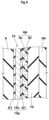
FIG. 2 is a development of a carcass ply; -
FIG. 3 is an enlarged view of a bead portion inFIG. 1 ; -
FIG. 4 is a sectional view taken along a line A-A inFIG. 3 ; and -
FIG. 5 is an enlarged view of the bead portion inFIG. 1 . - Hereinafter, an embodiment of the present invention will be described with reference to the drawings.
- The drawings contain exaggerated expressions and expressions that differ from the dimensional ratio of the actual structure in order to help the understanding of the present invention. In addition, when there are a plurality of embodiments, the same or common elements are denoted by the same reference characters throughout the description, and the redundant description thereof is omitted.
-
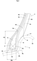
FIG. 1 is a tire meridional cross-sectional view, including a tire rotation axis (not shown), of the right half of a pneumatic tire (hereinafter, may be simply referred to as "tire") 1 according to one embodiment of the present invention.FIG. 1 shows thetire 1 for a passenger car as a preferable mode. The present invention is particularly suitable for a tire to be mounted to a commercial vehicle (e.g., van) designed for high-load applications. However, the present invention may be applied to atire 1 for a small-sized truck or a heavy-load vehicle, for example. - In the present description, unless otherwise specified, dimensions and the like of components of the
tire 1 are values measured in a standardized state. The "standardized state" is a state where thetire 1 is fitted on a standardized rim (hereinafter, may be simply referred to as "rim") R and inflated to a standardized internal pressure and no load is applied to thetire 1. - The "standardized rim R" is a rim that is defined, in a standard system including a standard on which the tire is based, by the standard for each tire, and is, for example, the "standard rim" in the JATMA standard, the "Design Rim" in the TRA standard, or the "Measuring Rim" in the ETRTO standard.
- The "standardized internal pressure" is an air pressure that is defined, in a standard system including a standard on which the tire is based, by the standard for each tire, and is the "maximum air pressure" in the JATMA standard, the maximum value indicated in the table "TIRE LOAD LIMITS AT VARIOUS COLD INFLATION PRESSURES" in the TRA standard, or the "INFLATION PRESSURE" in the ETRTO standard.
- The
tire 1 of the present embodiment includes atread portion 2, a pair ofsidewall portions 3, and a pair ofbead portions 4 respectively having beadcores 5.FIG. 1 shows only one of thesidewall portions 3 and one of thebead portions 4. In the present embodiment, thetire 1 also includes acarcass 6 extending between the pair ofbead portions 4, abelt layer 7 disposed outward of thecarcass 6 in a tire radial direction, and reinforcingrubber layers 10 respectively provided at the pair ofbead portions 4. - The
carcass 6 is acarcass ply 6A which includes abody portion 6a extending between thebead cores 5 of the pair ofbead portions 4, and a pair of turned-upportions 6b respectively turned up around thebead cores 5 from an inner side toward an outer side in a tire axial direction, extending outward in the tire radial direction, and havingouter ends 6e. Thus, thecarcass 6 of the present embodiment is formed of onecarcass ply 6A, thereby achieving weight reduction. - In the tire meridional cross-section in a standardized state, the pair of turned-up
portions 6b includefirst portions 11,second portions 12, andthird portions 13. Thefirst portions 11 are located between thebody portion 6a and thebelt layer 7. Thesecond portions 12 are adjacent to the reinforcingrubber layers 10 in the tire axial direction, on an outer side in the tire radial direction with respect to rim flanges Rf of the rim R. Thethird portions 13 are located between thefirst portions 11 and thesecond portions 12. Thefirst portions 11 and thesecond portions 12 are respectively supported by thebelt layer 7 and the reinforcingrubber layers 10, and tension that acts on each turned-upportion 6b is alleviated, thereby maintaining durability. In addition, the reinforcingrubber layers 10 serve to keep thecarcass ply 6A away from the rim flanges Rf, whereby damage to thecarcass ply 6A is inhibited, thereby maintaining durability at a higher level. - Each
first portion 11 includes a portion of the turned-upportion 6b that comes into contact with thebelt layer 7 when thebelt layer 7 is bent on the assumption that, in a case where a rubber material (e.g.,sidewall rubber 3G) is disposed between thebelt layer 7 and the turned-upportion 6b, nosidewall rubber 3G is provided. In addition, thefirst portion 11 is specified by a belt ply disposed on an innermost side in the tire radial direction (inner belt ply 7A in the present embodiment), in a case where thebelt layer 7 is formed of a plurality of belt plies. In addition, eachsecond portion 12 is formed outward of an outer end e1 in the tire radial direction of each rim flange Rf, in the tire radial direction. For convenience, inFIG. 1 , thefirst portion 11 and thesecond portion 12 are indicated by hatching. -
FIG. 2 is a development of thecarcass ply 6A. As shown inFIG. 2 , a length Lc of thethird portion 13 is preferably not less than 0.8 times and more preferably not less than 0.9 times a sum (La+Lb) of a length La of thefirst portion 11 and a length Lb of thesecond portion 12, and is preferably not greater than 1.4 times and more preferably not greater than 1.3 times the sum (La+Lb) of the length La of thefirst portion 11 and the length Lb of thesecond portion 12. Since the length Lc of thethird portion 13 is not less than 0.8 times the sum (La+Lb), the weight reduction oftire 1 is achieved. In addition, since the length Lc of thethird portion 13 is not greater than 1.4 times the sum (La+Lb), the effect that tension is alleviated by thefirst portion 11 and thesecond portion 12 is maintained at a high level. Therefore, thetire 1 of the present invention can achieve weight reduction while maintaining durability. Such an effect effectively contributes to, in particular, thepneumatic tire 1 to be mounted to a commercial vehicle designed for high-load applications. - In general, during running with the
tire 1, a relatively large tension acts on thecarcass ply 6A at thebead portions 4. Thus, the length Lb of thesecond portion 12 is preferably greater than the length La of thefirst portion 11. Although not particularly limited, the length Lb of thesecond portion 12 is preferably not less than 1.05 times and more preferably not less than 1.08 times the length La of thefirst portion 11, and is preferably not greater than 1.18 times and more preferably not greater than 1.15 times the length La of thefirst portion 11. - As shown in
FIG. 1 , in the present embodiment, thebelt layer 7 is formed of twobelt plies inner belt ply 7A, for example, terminates outward of theouter belt ply 7B in the tire axial direction. In the present embodiment, each of thebelt plies belt plies - As shown in
FIG. 2 , thecarcass ply 6A includes a plurality ofcarcass cords 6c and a topping rubber Gt for covering thecarcass cords 6c. Known materials may be used as appropriate for thecarcass cords 6c and the topping rubber Gt. - A length Wa (shown in
FIG. 1 ) in the tire axial direction between theouter ends 6e of the pair of turned-upportions 6b is preferably not less than 0.10 times and more preferably not less than 0.15 times a length L1 of thebody portion 6a, and is preferably not greater than 0.30 times and more preferably not greater than 0.25 times the length L1 of thebody portion 6a. Since the length Wa between theouter ends 6e is not less than 0.10 times the length L1 of thebody portion 6a, the weight reduction of thetire 1 is maintained at a high level. Since the length Wa between theouter ends 6e is not greater than 0.30 times the length L1 of thebody portion 6a, the effect of supporting the turned-upportions 6b is highly exerted. The length L1 of thebody portion 6a is a length betweenpositions 6i (shown inFIG. 1 ) located on an innermost side in the tire radial direction of thecarcass ply 6A. When a plurality of thepositions 6i located on the innermost side in the tire radial direction are formed, the length L1 is the length between positions located on the innermost side in the tire radial direction and further on an innermost side in the tire axial direction. - As shown in
FIG. 1 , in the tire meridional cross-section, eachbead core 5 of the present embodiment is formed in a rectangular shape. Thebead core 5 includes anouter surface 5a in the tire radial direction, aninner surface 5b in the tire radial direction, an inner-side surface 5c in the tire axial direction, and an outer-side surface 5d in the tire axial direction. The inner-side surface 5c and the outer-side surface 5d are connected to theouter surface 5a and theinner surface 5b. Thebead core 5 has a known structure that is formed by winding a non-stretchable bead wire, for example. - In the present embodiment, an
outer end 10e in the tire radial direction of each reinforcingrubber layer 10 is preferably located outward of the outer end e1 of each rim flange Rf in the tire radial direction. With such reinforcingrubber layers 10, deflection of thebead portion 4 is inhibited from being generated during running, and damage to thecarcass ply 6A can be further suppressed. In addition, deflection of thebead portion 4 is inhibited, whereby separation of tire components can be suppressed. Although not particularly limited, a distance H1 in the tire radial direction between theouter end 10e of the reinforcingrubber layer 10 and the outer end e1 of the rim flange Rf is preferably not less than 15% and more preferably not less than 20% of a tire cross-sectional height H, and is preferably not greater than 35% and more preferably not greater than 30% of the tire cross-sectional height H. In the present description, the "tire cross-sectional height H" is a distance in the tire radial direction from a bead base line BL to an outermost-side position in the tire radial direction. In addition, the "bead base line BL" is a line passing, in the tire axial direction, through a rim diameter (see JATMA) position defined by the standard on which thetire 1 is based. -
FIG. 3 is an enlarged view of thebead portion 4 inFIG. 1 . As shown inFIG. 1 andFIG. 3 , aninner end 10i in the tire radial direction of each reinforcingrubber layer 10 is preferably located outward of theouter surface 5a in the tire radial direction of eachbead core 5, in the tire radial direction. Such reinforcingrubber layers 10 suppress increase in mass of thetire 1. In addition, theinner end 10i of the reinforcingrubber layer 10 is, for example, located inward of the outer end e1 of each rim flange Rf in the tire radial direction. Thus, the stiffness of thebead portions 4 is maintained at a high level. - The reinforcing
rubber layer 10 is, for example, formed of a sheet-shaped rubber member. Such reinforcingrubber layers 10 enhance the stiffness of thebead portions 4 uniformly in the tire radial direction, and inhibit increase in the mass of thetire 1. A thickness (maximum thickness) t1 of each reinforcingrubber layer 10 is preferably 0.5 to 3.0 mm. In addition, for example, a complex elastic modulus E*c of the reinforcingrubber layer 10 is preferably not less than 15 MPa and more preferably not less than 20 MPa, and is preferably not greater than 100 MPa and more preferably not greater than 80 MPa. Thus, the stiffness of thebead portions 4 is maintained at a high level. In the present description, the complex elastic modulus E* is a value measured by using a viscoelasticity spectrometer such as "EPLEXOR (registered trademark)" manufactured by GABO under the following conditions in accordance with JIS K 6394. - Initial strain: 10%
- Amplitude: ±2%
- Frequency: 10 Hz
- Deformation mode: tension
- Temperature: 70°C
- As shown in
FIG. 1 , thetire 1 of the present embodiment further includesbead apex rubbers 8, reinforcinglayers 15, thesidewall rubbers 3G, and clinchrubbers 4G. For example, thebead apex rubbers 8 are respectively provided at the pair ofbead portions 4, and extend outward in the tire radial direction from theouter surfaces 5a in the tire radial direction of thebead cores 5. For example, the reinforcinglayers 15 are respectively provided at the pair ofbead portions 4, and are each disposed between thebead core 5 and thecarcass ply 6A. In the present embodiment, thesidewall rubbers 3G are disposed outward of the turned-upportions 6b in the tire axial direction, and are adjacent to thethird portions 13. For example, eachclinch rubber 4G is located outward of the reinforcingrubber layer 10 in the tire axial direction, and forms an outer surface, of thetire 1, in contact with the rim R. - As shown in
FIG. 3 , each reinforcinglayer 15 of the present embodiment includes an inner-side portion 15A and an outer-side portion 15B. The inner-side portion 15A is adjacent to the inner-side surface 5c of eachbead core 5, for example. The outer-side portion 15B is connected to the inner-side portion 15A, and is turned up around thebead core 5 from the inner side toward the outer side in a the tire axial direction and extends outward in the tire radial direction, for example. - An
outer end 15e of the inner-side portion 15A and anouter end 15i of the outer-side portion 15B are located outward of theouter surface 5a of thebead core 5 in the tire radial direction. In addition, theouter end 15e of the inner-side portion 15A and theouter end 15i of the outer-side portion 15B are located outward of theinner end 10i in the tire radial direction of the reinforcingrubber layer 10, in the tire radial direction. Such reinforcinglayers 15 greatly reduce a possibility that eachbead core 5 and thecarcass ply 6A come into contact with each other. Thus, there is less risk of breaking of thecarcass cords 6c of thecarcass ply 6A, thereby improving durability. Theouter end 15e of the inner-side portion 15A and theouter end 15i of the outer-side portion 15B are located inward of the outer end e1 of the rim flange Rf in the tire radial direction. - The
outer end 15e in the tire radial direction of the inner-side portion 15A and theouter end 15i in the tire radial direction of the outer-side portion 15B are at the same position in the tire radial direction. Such reinforcinglayers 15 suppress movement of thebead cores 5 or rotation around the shownbead cores 5, thereby further inhibiting contact between thecarcass ply 6A and eachbead core 5. In the present description, the "same position" refers to not only a case where a separation distance Lt in the tire radial direction between theouter end 15e and theouter end 15i is 0 mm but also a case where the separation distance Lt is not greater than 3 mm. - A distance Lp in the tire radial direction between the
outer end 15i of the outer-side portion 15B and theouter surface 5a of thebead core 5 is preferably not less than 30% and more preferably not less than 35% of a height H2 (shown inFIG. 5 ) in the tire radial direction of eachbead apex rubber 8, and is preferably not greater than 50% and more preferably not greater than 45% of the height H2 in the tire radial direction of thebead apex rubber 8. Since the distance Lp is not less than 30% of the height H2 of thebead apex rubber 8, contact between thecarcass ply 6A and eachbead core 5 can be effectively suppressed. Since the distance Lp is not greater than 50% of the height H2 of thebead apex rubber 8, the adhesion strength between eachbead apex rubber 8 and thecarcass ply 6A is maintained at a high level, thereby inhibiting damage due to separation. The height H2 of thebead apex rubber 8 is a length in the tire radial direction between anouter end 8e of thebead apex rubber 8 and theouter surface 5a of thebead core 5. -
FIG. 4 is a sectional view taken along a line A-A inFIG. 3 . As shown inFIG. 4 , in the present embodiment, each reinforcinglayer 15 is a reinforcing ply 15p including a plurality of organic fiber cords 15c and a first rubber G1 for covering the organic fiber cords 15c. For the organic fiber cords 15c, for example, polyester fibers, nylon fibers, rayon fibers, vinylon fibers, aramid fibers, or polyurethane fibers are used. - A product (Ca×E*1) of a cord density Ca of the
carcass ply 6A and a complex elastic modulus E*1 of the topping rubber Gt is preferably greater than a product (Cb×E*2) of a cord density Cb of the reinforcing ply 15p and a complex elastic modulus E*2 of the first rubber G1. Thus, the reinforcinglayer 15 can be accurately disposed along the inner-side surface 5c or theinner surface 5b of eachbead core 5, and damage to thecarcass ply 6A can be suppressed. The product (Ca×E*1) is, for example, preferably 90000 to 110000 (the number of the cords·MPa). The product (Cb×E*2) is, for example, preferably 15000 to 25000 (the number of the cords·MPa). In the present description, the "cord density" is the number of cords included per ply width of 50 mm in each ply. -
FIG. 5 is an enlarged view of thebead portion 4 inFIG. 1 . As shown inFIG. 5 , eachbead apex rubber 8 is inclined outward in the tire axial direction, toward the outer side in the tire radial direction. For thebead apex rubber 8 of the present embodiment, a known bead apex rubber can be used as appropriate. - The
outer end 8e in the tire radial direction of thebead apex rubber 8 is, for example, located outward of the outer end e1 of each rim flange Rf in the tire radial direction. Thus, deflection of thebead portions 4 during running is further suppressed, and, for example, separation between thecarcass ply 6A and each reinforcingrubber layer 10, separation between thebody portion 6a and each turned-upportion 6b, or the like is inhibited, thereby improving durability. In the present embodiment, thebead apex rubber 8 extends inward and outward of the outer end e1 of the rim flange Rf in the tire radial direction. - The height H2 in the tire radial direction of the
bead apex rubber 8 is preferably not greater than 30 mm and more preferably not greater than 28 mm. Since the height H2 of thebead apex rubber 8 is not greater than 30 mm, theouter end 8e of thebead apex rubber 8 and a bending point to be generated in thebead portion 4 during running are inhibited from coming excessively close to each other, thereby maintaining durability at a high level. Although not particularly limited, the height H2 of thebead apex rubber 8 is preferably not less than 5 mm and more preferably not less than 10 mm. - In the present embodiment, the
inner end 3i in the tire radial direction of eachsidewall rubber 3G is located inward of the outer end e1 of the rim flange Rf in the tire radial direction. Anouter end 3e (shown inFIG. 1 ) in the tire radial direction of thesidewall rubber 3G is, for example, located between theinner belt ply 7A and each turned-upportion 6b. - A thickness (maximum thickness) t3 (shown in
FIG. 1 ) of eachsidewall rubber 3G is preferably not less than 2.0 mm and more preferably not less than 2.5 mm, and is preferably not greater than 6.0 mm and more preferably not greater than 5.0 mm. Since the thickness t3 of thesidewall rubber 3G is not less than 2.0 mm, the stiffness of thesidewall portion 3 can be enhanced. Since the thickness t3 of thesidewall rubber 3G is not greater than 6.0 mm, weight reduction in thetire 1 can be maintained. The thickness t3 of thesidewall rubber 3G is a length in the direction normal to an outer surface in the tire axial direction of the turned-upportion 6b of thecarcass ply 6A. - In the present embodiment, an
outer end 4e in the tire radial direction of eachclinch rubber 4G is located outward of theouter end 8e of thebead apex rubber 8 in the tire radial direction. Theclinch rubber 4G is adjacent to the outer-side surface 5d of eachbead core 5 and extends inward of theinner surface 5b of thebead core 5 in the tire radial direction, for example. - A complex elastic modulus E*5 of each
bead apex rubber 8 is preferably not less than 15 MPa and more preferably not less than 20 MPa, and is preferably not greater than 100 MPa and more preferably not greater than 80 MPa. In addition, a complex elastic modulus E*6 of eachsidewall rubber 3G is preferably not less than 3 MPa and more preferably not less than 5 MPa, and is preferably not greater than 20 MPa and more preferably not greater than 15 MPa. A complex elastic modulus E*7 of eachclinch rubber 4G is preferably not less than 5 MPa and more preferably not less than 8 MPa, and is preferably not greater than 20 MPa and more preferably not greater than 15 MPa. - Bead toes Bt are each an innermost contact point with the rim R in the tire axial direction. Bead heels Bh are each a point that is in contact with the rim R and lies on the bead base line BL. A length Wb in the tire axial direction between the bead toe Bt and the bead heel Bh at each of the pair of
bead portions 4 is preferably not greater than 16 mm. With such length Wb, rim fittability when thetire 1 is fitted on the rim R is improved. In order to ensure stability during running, the length Wb is preferably not less than 12 mm. - Although the particularly preferred embodiment of the present invention has been described in detail above, the present invention is not limited to the illustrated embodiment, and various modifications can be made to implement the present invention.
- Pneumatic tires for passenger cars with a size of 205/85R16 having the basic structure in
FIG. 1 were produced as test tires on the basis of specifications in Table 1. Each test tire was tested for weight reduction, rim fittability, and durability. The test method is as follows. - The mass of each test tire was measured. The result was indicated as an index with the reciprocal of the mass of the tire of Comparative Example 3 being regarded as 100. The higher the numerical value is, the smaller the mass of the tire is and the more favorable the result is.
- Running with each test tire set on a drum tester under the following conditions was performed, and the running distance was measured when carcass cord damage or separation damage occurred. The carcass cord damage means damage caused due to the carcass cord being broken around the bead core. The separation damage means separation between the carcass ply and a constituent material adjacent thereto or separation between the carcass plies. The running distance was evaluated when one of the carcass cord damage or the separation damage occurred. The result was indicated as an index with the running distance of Comparative Example 1 being regarded as 60. A numerical value not less than 90 is acceptable.
- Internal pressure: 600 kPa
- Load: 19.84 kN
- Running speed: 80 km/h
- The test results are shown in Table 1 and Table 2.
- In Table 1, "Two" indicates an example in which two carcass plies were disposed and the outer ends 6e of the turned-up portions of each carcass ply were located at a tire maximum width position.
- In Tables 1 and 2, "A" means "8e>e1>15e, 15i", and "B" means "e1>8e>15e, 15i".
- Further, in Tables 1 and 2, "C" means "(Ca×E*1)>(Cb×E*2)", and "D" means "(Ca×E*1)<(Cb×E*2)".
- In Tables 1 and 2, "Presence" means that the reinforcing layer was formed of a reinforcing ply, and "Presence*" means that the reinforcing layer was formed of only rubber.
- Further, Comparative Example 1 is an example in which the height H2 in the tire radial direction of the bead apex rubber was the same height as that in
FIG. 1 , and Comparative Example 2 is an example in which the height H2 of the bead apex rubber was set so as to have a durability of 100.[Table 1] Comp. Ex. 1 Comp. Ex. 2 Comp. Ex. 3 Comp. Ex. 4 Ex. 1 Ex. 2 Ex. 3 Ex. 4 Shape of carcass ply Two Two FIG. 1 FIG. 1 FIG. 1 FIG. 1 FIG. 1 FIG. 1 Shape of bead portion no reinforcing rubber layer no reinforcing rubber layer FIG. 3 FIG. 3 FIG. 3 FIG. 3 FIG. 3 FIG. 3 Presence/absence of reinforcing layer Absence Absence Presence Presence Presence Presence Presence Presence Lc/(La+Lb) - - 0.7 1.5 0.8 0.9 1.3 1.4 Positions of 8e, 15e, e1 - - A A A A A A WaIL 1 - - 0.2 0.2 0.2 0.2 0.2 0.2 Relationship between (Ca×E*1) and (Cb×E*2) - - C C C C C C Wb (mm) 16 16 16 16 16 16 16 16 Weight reduction [Index, higher numerical value is better] 140 100 120 140 123 125 130 135 Durability [Index, higher numerical value is better] 80 100 88 85 95 100 105 100 [Table 2] Ex. 5 Ex. 6 Ex. 7 Ex. 8 Ex. 9 Ex. 10 Ex. 11 Shape of carcass ply FIG. 1 FIG. 1 FIG. 1 FIG. 1 FIG. 1 FIG. 1 FIG. 1 Shape of bead portion FIG. 3 FIG. 3 FIG. 3 FIG. 3 FIG. 3 FIG. 3 FIG. 3 Presence/absence of reinforcing layer Presence Presence* Absence Presence Presence Presence Presence Lc/(La+Lb) 1.2 1.2 1.2 1.2 1.2 1.2 1.2 Positions of 8e, 15e, e1 A A A A B A A Wa/L1 0.2 0.2 0.2 0.2 0.2 0.4 0.2 Relationship between (Ca×E*1) and (Cb×E*2) C C C C C C D Wb (mm) 16 16 16 18 16 16 17 Weight reduction [Index, higher numerical value is better] 127 132 135 127 130 135 127 Durability [Index, higher numerical value is better] 110 100 90 105 100 95 105 - As shown in Tables 1 and 2, it is understood that the weight reduction of the tires of the Examples is maintained and durability thereof is improved as compared to those of the tires of the Comparative Examples.
- The present invention includes the following aspects.
- A pneumatic tire including:
- a tread portion;
- a pair of sidewall portions;
- a pair of bead portions respectively having bead cores;
- a carcass extending between the pair of bead portions;
- a belt layer disposed outward of the carcass in a tire radial direction; and
- reinforcing rubber layers respectively provided at the pair of bead portions, wherein
- the carcass is a carcass ply which includes a body portion extending between the bead cores of the pair of bead portions, and a pair of turned-up portions respectively turned up around the bead cores from an inner side toward an outer side in a tire axial direction, extending outward in the tire radial direction, and having outer ends, and
- in a tire meridional cross-section in a standardized state where the pneumatic tire is fitted on a standardized rim and inflated to a standardized internal pressure and no load is applied to the pneumatic tire,
- each of the pair of turned-up portions includes a first portion located between the body portion and the belt layer, a second portion adjacent to each reinforcing rubber layer in the tire axial direction, on an outer side in the tire radial direction with respect to a rim flange of the standardized rim, and a third portion disposed between the first portion and the second portion, and
- a length of the third portion is 0.8 to 1.4 times a sum of a length of the first portion and a length of the second portion.
- The pneumatic tire according to
Present Invention 1, wherein a length in the tire axial direction between the outer ends of the pair of turned-up portions is 0.1 to 0.3 times a length of the body portion. - The pneumatic tire according to
Present Invention - The pneumatic tire according to
Present Invention 3, wherein - each of the pair of bead portions includes a bead apex rubber extending outward in the tire radial direction from an outer surface in the tire radial direction of the bead core, and
- in the standardized state,
- an outer end in the tire radial direction of the bead apex rubber and an outer end in the tire radial direction of the reinforcing rubber layer are located outward of an outer end in the tire radial direction of the rim flange of the standardized rim, in the tire radial direction.
- The pneumatic tire according to
Present Invention - the reinforcing layer includes an inner-side portion adjacent to an inner-side surface in the tire axial direction of the bead core, and an outer-side portion which is connected to the inner-side portion and is turned up around the bead core from the inner side toward the outer side in the tire axial direction and extends outward in the tire radial direction, and
- an outer end in the tire radial direction of the inner-side portion and an outer end in the tire radial direction of the outer-side portion are located at the same position, in the tire radial direction.
- The pneumatic tire according to
Present Invention 5, wherein the outer end in the tire radial direction of the inner-side portion and the outer end in the tire radial direction of the outer-side portion are located outward of an inner end in the tire radial direction of the reinforcing rubber layer, in the tire radial direction. - The pneumatic tire according to any one of
Present Inventions 3 to 6, wherein the reinforcing layer is a reinforcing ply including a plurality of organic fiber cords and a first rubber for covering the organic fiber cords. - The pneumatic tire according to any one of
Present Inventions 1 to 7, wherein the inner end in the tire radial direction of the reinforcing rubber layer is located outward of the outer surface in the tire radial direction of the bead core, in the tire radial direction. - The pneumatic tire according to
Present Invention 7, wherein - the carcass ply includes a plurality of carcass cords and a topping rubber for covering the carcass cords, and
- a product of a cord density of the carcass ply and a complex elastic modulus of the topping rubber is greater than a product of a cord density of the reinforcing ply and a complex elastic modulus of the first rubber.
- The pneumatic tire according to any one of
Present Inventions 1 to 9, wherein
in each of the pair of bead portions, a length in the tire axial direction between a bead toe and a bead heel is not greater than 16 mm. - The pneumatic tire according to any one of
Present Inventions 1 to 10, wherein - a sidewall rubber is provided adjacent to an outer side in the tire axial direction of the third portion, and
- a thickness of the sidewall rubber is 2.0 to 6.0 mm.
Claims (11)
- A pneumatic tire (1) comprising:a tread portion (2);a pair of sidewall portions (3);a pair of bead portions (4) respectively having bead cores (5);a carcass (6) extending between the pair of bead portions (4);a belt layer (7) disposed outward of the carcass (6) in a tire radial direction; andreinforcing rubber layers (10) respectively provided at the pair of bead portions (4), whereinthe carcass (6) is a carcass ply (6A) which includes a body portion (6a) extending between the bead cores (5) of the pair of bead portions (4), and a pair of turned-up portions (6b) respectively turned up around the bead cores (5) from an inner side toward an outer side in a tire axial direction, extending outward in the tire radial direction, and having outer ends (6e), andin a tire meridional cross-section in a standardized state where the pneumatic tire (1) is fitted on a standardized rim (R) and inflated to a standardized internal pressure and no load is applied to the pneumatic tire (1),each of the pair of turned-up portions (6b) includes a first portion (11) located between the body portion (6a) and the belt layer (7), a second portion (12) adjacent to each reinforcing rubber layer (10) in the tire axial direction, on an outer side in the tire radial direction with respect to a rim flange (Rf) of the standardized rim (R), and a third portion (13) disposed between the first portion (11) and the second portion (12), anda length (Lc) of the third portion (13) is 0.8 to 1.4 times a sum of a length (La) of the first portion (11) and a length (Lb) of the second portion (12).
- The pneumatic tire (1) according to claim 1, wherein a length (Wa) in the tire axial direction between the outer ends (6e) of the pair of turned-up portions (6b) is 0.1 to 0.3 times a length (L1) of the body portion (6a).
- The pneumatic tire (1) according to claim 1 or 2, wherein each of the pair of bead portions (4) includes a reinforcing layer (15) provided between the bead core (5) and the carcass ply (6A).
- The pneumatic tire (1) according to claim 3, whereineach of the pair of bead portions (4) includes a bead apex rubber (8) extending outward in the tire radial direction from an outer surface (5a) in the tire radial direction of the bead core (5), andin the standardized state,an outer end (8e) in the tire radial direction of the bead apex rubber (8) and an outer end (10e) in the tire radial direction of the reinforcing rubber layer (10) are located outward of an outer end (e1) in the tire radial direction of the rim flange (Rf) of the standardized rim (R), in the tire radial direction.
- The pneumatic tire (1) according to claim 3 or 4, whereinthe reinforcing layer (15) includes an inner-side portion (15A) adjacent to an inner-side surface (5c) in the tire axial direction of the bead core (5), and an outer-side portion (15B) which is connected to the inner-side portion (15A) and is turned up around the bead core (5) from the inner side toward the outer side in the tire axial direction and extends outward in the tire radial direction, andan outer end (15e) in the tire radial direction of the inner-side portion (15A) and an outer end (15i) in the tire radial direction of the outer-side portion (15B) are located at the same position, in the tire radial direction.
- The pneumatic tire (1) according to claim 5, wherein the outer end (15e) in the tire radial direction of the inner-side portion (15A) and the outer end (15i) in the tire radial direction of the outer-side portion (15B) are located outward of an inner end (10i) in the tire radial direction of the reinforcing rubber layer (10), in the tire radial direction.
- The pneumatic tire (1) according to any one of claims 3 to 6, wherein the reinforcing layer (15) is a reinforcing ply (15p) including a plurality of organic fiber cords (15c) and a first rubber (G1) for covering the organic fiber cords (15c).
- The pneumatic tire (1) according to any one of claims 1 to 7, wherein the inner end (10i) in the tire radial direction of the reinforcing rubber layer (10) is located outward of the outer surface (5a) in the tire radial direction of the bead core (5), in the tire radial direction.
- The pneumatic tire (1) according to claim 7, whereinthe carcass ply (6A) includes a plurality of carcass cords (6c) and a topping rubber (Gt) for covering the carcass cords (6c), anda product of a cord density (Ca) of the carcass ply (6A) and a complex elastic modulus (E*1) of the topping rubber (Gt) is greater than a product of a cord density (Cb) of the reinforcing ply (15p) and a complex elastic modulus (E*2) of the first rubber (G1).
- The pneumatic tire (1) according to any one of claims 1 to 9, wherein
in each of the pair of bead portions (4), a length (Wb) in the tire axial direction between a bead toe (Bt) and a bead heel (Bh) is not greater than 16 mm. - The pneumatic tire (1) according to any one of claims 1 to 10, whereina sidewall rubber (3G) is provided adjacent to an outer side in the tire axial direction of the third portion (13), anda thickness (t3) of the sidewall rubber (3G) is 2.0 to 6.0 mm.
Applications Claiming Priority (2)
| Application Number | Priority Date | Filing Date | Title |
|---|---|---|---|
| JP2023135711 | 2023-08-23 | ||
| JP2024098279A JP2025031539A (en) | 2023-08-23 | 2024-06-18 | Pneumatic tires |
Publications (2)
| Publication Number | Publication Date |
|---|---|
| EP4512639A1 true EP4512639A1 (en) | 2025-02-26 |
| EP4512639B1 EP4512639B1 (en) | 2026-02-25 |
Family
ID=92172042
Family Applications (1)
| Application Number | Title | Priority Date | Filing Date |
|---|---|---|---|
| EP24192059.4A Active EP4512639B1 (en) | 2023-08-23 | 2024-07-31 | Pneumatic tire |
Country Status (2)
| Country | Link |
|---|---|
| US (1) | US20250065674A1 (en) |
| EP (1) | EP4512639B1 (en) |
Citations (5)
| Publication number | Priority date | Publication date | Assignee | Title |
|---|---|---|---|---|
| US3052275A (en) * | 1959-05-12 | 1962-09-04 | Goodyear Tire & Rubber | Pneumatic tire |
| EP1095796A2 (en) * | 1999-10-27 | 2001-05-02 | Sumitomo Rubber Industries Limited | Tubeless tyre |
| US20130118669A1 (en) * | 2011-11-10 | 2013-05-16 | Matthew F. Krietemeyer | Reinforced Radial Tire |
| US20200331302A1 (en) * | 2017-12-04 | 2020-10-22 | The Yokohama Rubber Co., Ltd. | Pneumatic Tire |
| JP2022100772A (en) | 2020-12-24 | 2022-07-06 | 住友ゴム工業株式会社 | tire |
-
2024
- 2024-07-30 US US18/788,177 patent/US20250065674A1/en active Pending
- 2024-07-31 EP EP24192059.4A patent/EP4512639B1/en active Active
Patent Citations (5)
| Publication number | Priority date | Publication date | Assignee | Title |
|---|---|---|---|---|
| US3052275A (en) * | 1959-05-12 | 1962-09-04 | Goodyear Tire & Rubber | Pneumatic tire |
| EP1095796A2 (en) * | 1999-10-27 | 2001-05-02 | Sumitomo Rubber Industries Limited | Tubeless tyre |
| US20130118669A1 (en) * | 2011-11-10 | 2013-05-16 | Matthew F. Krietemeyer | Reinforced Radial Tire |
| US20200331302A1 (en) * | 2017-12-04 | 2020-10-22 | The Yokohama Rubber Co., Ltd. | Pneumatic Tire |
| JP2022100772A (en) | 2020-12-24 | 2022-07-06 | 住友ゴム工業株式会社 | tire |
Also Published As
| Publication number | Publication date |
|---|---|
| US20250065674A1 (en) | 2025-02-27 |
| EP4512639B1 (en) | 2026-02-25 |
Similar Documents
| Publication | Publication Date | Title |
|---|---|---|
| US11618283B2 (en) | Pneumatic tire | |
| EP3127717B1 (en) | Pneumatic tire | |
| US11142027B2 (en) | Pneumatic tire | |
| EP2818332B1 (en) | Pneumatic tire | |
| EP3281805B1 (en) | Pneumatic tire | |
| JP4648560B2 (en) | Run flat tire | |
| EP3357715B1 (en) | Pneumatic tire | |
| JP3540966B2 (en) | Pneumatic radial tire | |
| CN106671707B (en) | Run flat tire | |
| US20040226644A1 (en) | Discontinuous ply for runflat tire construction | |
| US10518592B2 (en) | Pneumatic tire | |
| US12214628B2 (en) | Pneumatic tire | |
| EP3636454B1 (en) | Tire | |
| EP4512639B1 (en) | Pneumatic tire | |
| JPH0958229A (en) | Pneumatic radial tire | |
| EP3536522B1 (en) | Run flat tire | |
| JP2025031539A (en) | Pneumatic tires | |
| US10744826B2 (en) | Pneumatic tire | |
| US20240294040A1 (en) | Pneumatic tire | |
| JP6529127B2 (en) | Pneumatic tire | |
| EP4410569A1 (en) | Pneumatic tire | |
| EP4282668B1 (en) | Pneumatic tire | |
| EP3900954B1 (en) | Pneumatic tyre | |
| EP4282667B1 (en) | Pneumatic tire | |
| EP4063147A1 (en) | Pneumatic tire |
Legal Events
| Date | Code | Title | Description |
|---|---|---|---|
| PUAI | Public reference made under article 153(3) epc to a published international application that has entered the european phase |
Free format text: ORIGINAL CODE: 0009012 |
|
| STAA | Information on the status of an ep patent application or granted ep patent |
Free format text: STATUS: THE APPLICATION HAS BEEN PUBLISHED |
|
| AK | Designated contracting states |
Kind code of ref document: A1 Designated state(s): AL AT BE BG CH CY CZ DE DK EE ES FI FR GB GR HR HU IE IS IT LI LT LU LV MC ME MK MT NL NO PL PT RO RS SE SI SK SM TR |
|
| P01 | Opt-out of the competence of the unified patent court (upc) registered |
Free format text: CASE NUMBER: APP_12458/2025 Effective date: 20250313 |
|
| STAA | Information on the status of an ep patent application or granted ep patent |
Free format text: STATUS: REQUEST FOR EXAMINATION WAS MADE |
|
| 17P | Request for examination filed |
Effective date: 20250715 |
|
| GRAP | Despatch of communication of intention to grant a patent |
Free format text: ORIGINAL CODE: EPIDOSNIGR1 |
|
| STAA | Information on the status of an ep patent application or granted ep patent |
Free format text: STATUS: GRANT OF PATENT IS INTENDED |
|
| INTG | Intention to grant announced |
Effective date: 20251210 |
|
| GRAS | Grant fee paid |
Free format text: ORIGINAL CODE: EPIDOSNIGR3 |
|
| GRAA | (expected) grant |
Free format text: ORIGINAL CODE: 0009210 |
|
| STAA | Information on the status of an ep patent application or granted ep patent |
Free format text: STATUS: THE PATENT HAS BEEN GRANTED |
|
| AK | Designated contracting states |
Kind code of ref document: B1 Designated state(s): AL AT BE BG CH CY CZ DE DK EE ES FI FR GB GR HR HU IE IS IT LI LT LU LV MC ME MK MT NL NO PL PT RO RS SE SI SK SM TR |
|
| REG | Reference to a national code |
Ref country code: CH Ref legal event code: F10 Free format text: ST27 STATUS EVENT CODE: U-0-0-F10-F00 (AS PROVIDED BY THE NATIONAL OFFICE) Effective date: 20260225 Ref country code: GB Ref legal event code: FG4D |
|
| REG | Reference to a national code |
Ref country code: DE Ref legal event code: R096 Ref document number: 602024002796 Country of ref document: DE |
|
| REG | Reference to a national code |
Ref country code: IE Ref legal event code: FG4D |