EP4512637A1 - Tire for heavy load - Google Patents
Tire for heavy load Download PDFInfo
- Publication number
- EP4512637A1 EP4512637A1 EP23826703.3A EP23826703A EP4512637A1 EP 4512637 A1 EP4512637 A1 EP 4512637A1 EP 23826703 A EP23826703 A EP 23826703A EP 4512637 A1 EP4512637 A1 EP 4512637A1
- Authority
- EP
- European Patent Office
- Prior art keywords
- cap
- layer
- tire
- thickness
- pair
- Prior art date
- Legal status (The legal status is an assumption and is not a legal conclusion. Google has not performed a legal analysis and makes no representation as to the accuracy of the status listed.)
- Pending
Links
Images

Classifications
-
- B—PERFORMING OPERATIONS; TRANSPORTING
- B60—VEHICLES IN GENERAL
- B60C—VEHICLE TYRES; TYRE INFLATION; TYRE CHANGING; CONNECTING VALVES TO INFLATABLE ELASTIC BODIES IN GENERAL; DEVICES OR ARRANGEMENTS RELATED TO TYRES
- B60C11/00—Tyre tread bands; Tread patterns; Anti-skid inserts
- B60C11/0041—Tyre tread bands; Tread patterns; Anti-skid inserts comprising different tread rubber layers
- B60C11/005—Tyre tread bands; Tread patterns; Anti-skid inserts comprising different tread rubber layers with cap and base layers
-
- B—PERFORMING OPERATIONS; TRANSPORTING
- B60—VEHICLES IN GENERAL
- B60C—VEHICLE TYRES; TYRE INFLATION; TYRE CHANGING; CONNECTING VALVES TO INFLATABLE ELASTIC BODIES IN GENERAL; DEVICES OR ARRANGEMENTS RELATED TO TYRES
- B60C11/00—Tyre tread bands; Tread patterns; Anti-skid inserts
- B60C11/0008—Tyre tread bands; Tread patterns; Anti-skid inserts characterised by the tread rubber
- B60C2011/0016—Physical properties or dimensions
- B60C2011/0025—Modulus or tan delta
-
- B—PERFORMING OPERATIONS; TRANSPORTING
- B60—VEHICLES IN GENERAL
- B60C—VEHICLE TYRES; TYRE INFLATION; TYRE CHANGING; CONNECTING VALVES TO INFLATABLE ELASTIC BODIES IN GENERAL; DEVICES OR ARRANGEMENTS RELATED TO TYRES
- B60C11/00—Tyre tread bands; Tread patterns; Anti-skid inserts
- B60C11/0008—Tyre tread bands; Tread patterns; Anti-skid inserts characterised by the tread rubber
- B60C2011/0016—Physical properties or dimensions
- B60C2011/0033—Thickness of the tread
-
- B—PERFORMING OPERATIONS; TRANSPORTING
- B60—VEHICLES IN GENERAL
- B60C—VEHICLE TYRES; TYRE INFLATION; TYRE CHANGING; CONNECTING VALVES TO INFLATABLE ELASTIC BODIES IN GENERAL; DEVICES OR ARRANGEMENTS RELATED TO TYRES
- B60C2200/00—Tyres specially adapted for particular applications
- B60C2200/06—Tyres specially adapted for particular applications for heavy duty vehicles
- B60C2200/065—Tyres specially adapted for particular applications for heavy duty vehicles for construction vehicles
Definitions
- heavy-duty tires are required to have two main performance characteristics: wear resistance and heat resistance (and therefore, durability).
- wear resistance and heat resistance (and therefore, durability).
- heat resistance and therefore, durability
- An object of the present disclosure is to provide a heavy-duty tire that is capable of achieving both wear resistance and heat resistance at a higher level.
- tires are pneumatic tires.
- Figures 1 and 2 are drawings to explain a heavy-duty tire 1 according to one embodiment of the present disclosure.
- Figure 1 is a cross-sectional view in the tire width direction, schematically illustrating a heavy-duty tire according to one embodiment of the present disclosure.
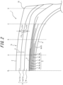
- Figure 2 is an enlarged view illustrating a part of the heavy-duty tire in Figure 1
- the heavy-duty tire 1 of the embodiment illustrated in Figures 1 and 2 are configured as a construction and mining vehicle tire (off-the-road tire). However, the heavy-duty tire 1 may be configured as any type of heavy-duty tire.
- each element shall be measured under the reference conditions where the tire 1 is mounted on the applicable rim, filled with the prescribed internal pressure, and unloaded.
- the width in the tire width direction of the contact patch which is in contact with the road surface is referred to as the "ground contact width”
- the edge in the tire width direction of the ground contact patch is referred to as the "ground contact edge”.
- the term "applicable rim” refers to the standard rim in the applicable size (Measuring Rim in ETRTO's STANDARDS MANUAL and Design Rim in TRA's YEAR BOOK) as described or as may be described in the future in the industrial standard, which is valid for the region in which the tire is produced and used, such as JATMA YEAR BOOK of JATMA (Japan Automobile Tyre Manufacturers Association) in Japan, STANDARDS MANUAL of ETRTO (The European Tyre and Rim Technical Organization) in Europe, and YEAR BOOK of TRA (The Tire and Rim Association, Inc.) in the United States.
- JATMA YEAR BOOK of JATMA Japan Automobile Tyre Manufacturers Association
- STANDARDS MANUAL of ETRTO The European Tyre and Rim Technical Organization
- TRA The Tire and Rim Association, Inc.
- the term “applicable rim” refers to a rim with a width corresponding to the bead width of the pneumatic tire.
- the “applicable rim” includes current sizes as well as future sizes to be listed in the aforementioned industrial standards.
- An example of the "size as described in the future” could be the sizes listed as " FUTURE DEVELOPMENTS" in the ETRTO 2013 editi on.
- the "prescribed internal pressure” refers to the air pressure (maximum air pressure) corresponding to the maximum load capacity of a single wheel in the applicable size and ply rating, as described in the aforementioned JATMA YEAR BOOK and other industrial standards. In the case that the size is not listed in the aforementioned industrial standards, the “prescribed internal pressure” refers to the air pressure (maximum air pressure) corresponding to the maximum load capacity specified for each vehicle in which the tire is mounted.
- maximum load means the load corresponding to the maximum load capacity in the tire of the applicable size described in the aforementioned industrial standards, or, for sizes not listed in the aforementioned industrial standards, the load corresponding to the maximum load capacity specified for each vehicle in which the tire is mounted.
- the tire 1 comprises a tread portion 1a, a pair of sidewall portions 1b extending radially inward from both ends in the tire width direction of the tread portion 1a, and a pair of bead portions 1c provided at the radially inner ends of each sidewall portion 1b.
- the bead portion 1c is configured so that it comes into contact with the rim on the inner side in the tire radial direction and the outer side in the tire width direction when the tire 1 is mounted on the rim.
- Each bead core 4a is embedded in the corresponding bead portion 1c.
- the bead core 4a comprises a plurality of bead wires that are covered with rubber.
- the bead wire is suitably made of metal (e.g. steel).
- the bead wire may be, for example, of monofilament or twisted wire.
- Each bead filler 4b is located on the outer side of the corresponding bead core 4a in the tire radial direction.
- the bead filler 4b tapers out towards the outer side in the tire radial direction.
- Bead filler 4b is made of rubber.
- bead fillers are sometimes called "stiffeners".
- the carcass 5 is straddled between the pair of bead cores 4a and extends in a toroidal shape.
- the carcass 5 is made up of one or more (in the example in Figure 1 , one) carcass ply 5a.
- Each carcass ply 5a contains one or more carcass cords and coating rubber that covers the carcass cords.
- the carcass cords may be of monofilaments or twisted wires.
- the carcass 5 is preferably of radial structure, but may also be of bias structure.
- the belt 6 is disposed on the outer side in the tire radial direction relative to the crown portion of the carcass 5.
- the belt 6 comprises one or more belt layers 6a (in the example in Figure 1 , 6 layers).
- Each belt layer 6a contains one or more belt cords and coating rubber that covers the belt cords.
- the belt cords may be of monofilaments or twisted wires.
- the belt cord is most suitable when it is made of metal (e.g. steel), but it may also be made of organic fibers such as polyester, nylon, rayon, or aramid.
- the tread rubber 7 is located on the outer side in the tire radial direction of the belt 6 in the tread portion 1a.
- the tread rubber 7 makes up a tread surface 2, which is the surface on the outer side in the tire radial direction of the tread portion 1a.
- the tread pattern is formed on the tread surface 2 by grooves and/or sipes. However, for simplicity, the illustration of the grooves and/or sipes provided on the tread surface 2 is omitted in Figure 1 . In Figure 2 , for reference, an example of a groove g that can be provided in the tread surface 2 is illustrated by a broken line.
- tread rubber 7 Further details of the tread rubber 7 will be explained later.
- the side rubber 8 is located in the sidewall portion 1b.
- the side rubber 8 makes up the outer surface in the tire width direction of the sidewall portion 1b.
- the side rubber 8 is located on the outer side in the tire width direction than the carcass 5.
- the side rubber 8 is located on the outer side in the tire width direction than the bead filler 4b.
- the side rubber 8 is molded as one piece with the tread rubber 7.
- the inner liner 9 is disposed on the tire inner side of the carcass 5 and may be laminated on the tire inner side of the carcass 5, for example.
- the inner liner 9 is made of, for example, a butyl-based rubber having low air permeability.
- the butyl-based rubbers include, for example, butyl rubber and its derivative, halogenated butyl rubber.
- the inner liner 9 can be made not only of butyl rubber, but also of other rubber compositions, resins, or elastomers.
- tread rubber 7 The following is a more detailed explanation of the tread rubber 7.
- the tread rubber 7 has a cap layer 7c and a base layer 7b.
- the base layer 7b is disposed closer to the inner circumferential side of tire than the cap layer 7c.
- the cap layer 7c comprises two layers: a cap surface layer 7c1 and a cap intermediate layer 7c2, and in this embodiment, it consists of these two layers.
- the cap intermediate layer 7c2 is disposed closer to the inner circumferential side of tire than the cap surface layer 7c1.
- the surface, on the outer circumferential side of tire, of the cap surface layer 7c1 constitutes the tread surface 2.
- the tread rubber 7 is made up of three layers: the cap surface layer 7c1, the cap intermediate layer 7c2, and the base layer 7b.
- the cap surface layer 7c1, the cap intermediate layer 7c2, and the base layer 7b each exist throughout the entire region in the tire width direction between the tire widthwise positions D of the pair of ground contact edges TE.
- the cap surface layer 7c1 has a larger tan ⁇ in a tensile test under conditions of: room temperature of 24°C, amplitude of 2%, and 50Hz than the cap intermediate layer 7c2.
- the difference between the tan ⁇ of the cap surface layer 7c1 in a tensile test under the conditions of: room temperature of 24°C, amplitude of 2%, and 50Hz, and the tan ⁇ of the cap intermediate layer 7c2 in a tensile test under the conditions of: room temperature of 24°C, amplitude of 2%, and 50Hz, is 0.03 or more.
- the cap surface layer 7c1 has higher wear resistance than the cap intermediate layer 7c2, and the cap intermediate layer 7c2 has higher heat resistance than the cap surface layer 7c1.
- the cap layer 7c of the tread rubber 7 comprises two layers: the cap surface layer 7c1 and the cap intermediate layer 7c2; the cap surface layer 7c1 has a larger tan ⁇ in a tensile test under conditions of: room temperature of 24°C, amplitude of 2%, and 50Hz than the cap intermediate layer 7c2; and the difference between the tan ⁇ of the cap surface layer 7c1 in a tensile test under the conditions of: room temperature of 24°C, amplitude of 2%, and 50Hz, and the tan ⁇ of the cap intermediate layer 7c2 in a tensile test under the conditions of: room temperature of 24°C, amplitude of 2%, and 50Hz, is 0.03 or more.
- the base layer 7b it is suitable if the tan ⁇ in a tensile test under the conditions of: room temperature of 24°C, amplitude of 2%, and 50Hz is lower by 0.03 or more than that of the cap intermediate layer 7c2. This makes it possible to achieve a higher level of compatibility between wear resistance and heat resistance.
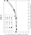
- Figure 3 provides the results of the FEM analysis conducted on the four tire models 1 to 4.
- the tire models 1 to 4 each have different tire sizes.
- the tread rubber 7 has a cap layer 7c and a base layer 7b, and the cap layer 7c is composed of the cap surface layer 7c1 and the cap intermediate layer 7c2 (however, this does not include the case when the ratio of the thickness t7c1 of the cap surface layer 7c1 to the thickness t7c of the cap layer 7c is 0% or 100%).
- the cap surface layer 7c1 has tan ⁇ of 0.25 in a tensile test under the conditions of: room temperature of 24°C, amplitude of 2%, and 50Hz, and is made of rubber with a total filler content (the total amount of carbon and silica) of 65 parts.
- the cap intermediate layer 7c2 has tan ⁇ of 0.19 in a tensile test under the conditions of: room temperature of 24°C, amplitude of 2%, and 50Hz, and is made of rubber with a total filler content (the total amount of carbon and silica) of 55 parts.
- the ratio of a thickness t7c1 of the cap surface layer 7c1 ( Figure 2 ) to a thickness t7c of the cap layer 7c ( Figure 2 ) is almost constant throughout the entire region in the tire width direction between a pair of tire widthwise positions D of the ground contact edges TE.
- the horizontal axis is the ratio (%) of the thickness of the cap surface layer 7c1 to the thickness of the cap layer 7c of each tire model.
- the vertical axis is the relative temperature (°C) compared to a given reference temperature, that occurred in a target analysis part X ( Figure 2 ) of each tire model when each tire model was made to perform a specified action.
- the target analysis part X is the part that is located approximately 3.5 mm on the outer circumferential side of tire from the outermost belt layer 6a in the belt 6 and is located near the tire equatorial plane CL in the tire width direction, as illustrated in Figure 2 .
- the above-mentioned reference temperature is, as in the past, the temperature (°C) that occurs in the part of the target analysis part X of the tire when the above-mentioned specified operation is performed on a given tire.
- the given tire is such tire, for example, which comprises a cap layer consisting of only one layer; and is made of rubber in which a tan ⁇ in a tensile test under the conditions of room temperature of 24°C, amplitude of 2%, and 50Hz is 0.19, and a total filler content (the total amount of carbon and silica) is 55 parts, as the physical properties used in the FEM calculation.
- the above-mentioned reference temperature can be used as an indicator of the heat resistance of conventional tires.
- the relative temperature of the target analysis part X of the tire model can be used as an indicator of the heat resistance of that tire model. If the relative temperature of the target analysis part X is 0°C, the heat resistance of the tire model is equivalent to that of conventional tires, and the lower the relative temperature of the target analysis part X, the higher the heat resistance of the tire model.
- the "thickness t7c of cap layer 7c" shall be measured parallel to the tire radial direction, as illustrated in Figure 2 .
- the ratio of the thickness t7c1 of the cap surface layer 7c1 to the thickness t7c of the cap layer 7c, t7c1/t7c, and the ratio of the thickness t7c1 of the cap surface layer 7c1 to the thickness t7c2 of the cap intermediate layer 7c2, t7c1/t7c2, may be constant or may vary along the tire width direction between the tire widthwise positions D of the pair of ground contact edges TE.
- the average value of the ratio of the thickness t7c1 of the cap surface layer 7c1 to the thickness t7c of the cap layer 7c in the part between the tire widthwise positions D of the pair of ground contact edges is 75% or less, more suitably 70% or less, and even more suitably 60% or less.
- the average value of the ratio of the thickness t7c1 of the cap surface layer 7c1 to the thickness t7c of the cap layer 7c in the part between the tire widthwise positions D of the pair of ground contact edges is 30% or more, more suitably 40% or more, and even more suitably 50% or more.
- the average value of the ratio of the thickness t7c1 of the cap surface layer 7c1 to the thickness t7c of the cap layer 7c, t7c1/ t7c, in the part on the center side (the side closer to the tire equatorial plane CL) may be lower than the average value of the ratio of the thickness t7c1 of the cap surface layer 7c1 to the thickness t7c of the cap layer 7c, t7c1/ t7c, in the part on the shoulder side (the side far from the tire equatorial plane CL).
Landscapes
- Engineering & Computer Science (AREA)
- Mechanical Engineering (AREA)
- Tires In General (AREA)
Abstract
Description
- This disclosure relates to a tire for heavy loads (heavy-duty tires).
- This application claims priority to Patent Application No.
2022-102137, filed in Japan on June 24, 2022 - There have been heavy-duty tires with tread rubber that has a cap layer and a base layer (Patent Document 1).
- PTL 1:
JP 2007-137411 A - Generally, heavy-duty tires are required to have two main performance characteristics: wear resistance and heat resistance (and therefore, durability). However, these performance characteristics are in a trade-off relationship, and it is not easy to achieve both.
- There was room for improvement in terms of achieving both wear resistance and heat resistance in conventional heavy-duty tires.
- An object of the present disclosure is to provide a heavy-duty tire that is capable of achieving both wear resistance and heat resistance at a higher level.
- The above object can be achieved by the following means.
- [1] A heavy-duty tire, wherein
- tread rubber has:
- a cap layer; and
- a base layer disposed on an inner circumferential side of tire than the cap layer,
- the cap layer comprises:
- a cap surface layer; and
- a cap intermediate layer,
- the cap surface layer has a larger tan δ in a tensile test under conditions of: room temperature of 24°C, amplitude of 2%, and 50Hz, than the cap intermediate layer, and
- difference between tan δ of the cap surface layer in a tensile test under conditions of: room temperature of 24°C, amplitude of 2%, and 50Hz, and tan δ of the cap intermediate layer in a tensile test under conditions of: room temperature of 24°C, amplitude of 2%, and 50Hz, is 0.03 or more.
- tread rubber has:
- According to the present disclosure, it is possible to provide a heavy-duty tire that is capable of achieving both wear resistance and heat resistance at a higher level.
- In the accompanying drawings:
-
FIG. 1 is a cross-sectional view in the tire width direction, schematically illustrating a heavy-duty tire according to one embodiment of the present disclosure; -
FIG. 2 is an enlarged view illustrating a part of the heavy-duty tire inFigure 1 ; and -
FIG. 3 provides the results of the analysis for a plurality of tire models. - The heavy-duty tires according to the present disclosure can be suitably used for any type of heavy-duty tire, and are particularly suitable for use in construction and mining vehicle tires (off-the-road tires).
- Hereinafter, embodiments of a heavy-duty tire according to the present disclosure will be described with reference to the drawings.
- The same components and parts are designated by the same reference numerals/symbols in each drawing.
- For convenience, heavy-duty tires, etc., are also referred to simply as "tires" in this document. In this document, tires are pneumatic tires.
-
Figures 1 and2 are drawings to explain a heavy-duty tire 1 according to one embodiment of the present disclosure.Figure 1 is a cross-sectional view in the tire width direction, schematically illustrating a heavy-duty tire according to one embodiment of the present disclosure.Figure 2 is an enlarged view illustrating a part of the heavy-duty tire inFigure 1 - The heavy-
duty tire 1 of the embodiment illustrated inFigures 1 and2 are configured as a construction and mining vehicle tire (off-the-road tire). However, the heavy-duty tire 1 may be configured as any type of heavy-duty tire. - Unless otherwise specified, the position and dimensions of each element shall be measured under the reference conditions where the
tire 1 is mounted on the applicable rim, filled with the prescribed internal pressure, and unloaded. - In addition, when the tire is mounted on the applicable rim, filled with the prescribed internal pressure, and loaded with the maximum load, the width in the tire width direction of the contact patch which is in contact with the road surface is referred to as the "ground contact width", and the edge in the tire width direction of the ground contact patch is referred to as the "ground contact edge".
- As used herein, the term "applicable rim" refers to the standard rim in the applicable size (Measuring Rim in ETRTO's STANDARDS MANUAL and Design Rim in TRA's YEAR BOOK) as described or as may be described in the future in the industrial standard, which is valid for the region in which the tire is produced and used, such as JATMA YEAR BOOK of JATMA (Japan Automobile Tyre Manufacturers Association) in Japan, STANDARDS MANUAL of ETRTO (The European Tyre and Rim Technical Organization) in Europe, and YEAR BOOK of TRA (The Tire and Rim Association, Inc.) in the United States. For sizes not listed in these industrial standards, the term "applicable rim" refers to a rim with a width corresponding to the bead width of the pneumatic tire. The "applicable rim" includes current sizes as well as future sizes to be listed in the aforementioned industrial standards. An example of the "size as described in the future" could be the sizes listed as "FUTURE DEVELOPMENTS" in the ETRTO 2013 edition.
- As used herein, the "prescribed internal pressure" refers to the air pressure (maximum air pressure) corresponding to the maximum load capacity of a single wheel in the applicable size and ply rating, as described in the aforementioned JATMA YEAR BOOK and other industrial standards. In the case that the size is not listed in the aforementioned industrial standards, the "prescribed internal pressure" refers to the air pressure (maximum air pressure) corresponding to the maximum load capacity specified for each vehicle in which the tire is mounted. Further, as used herein, the term "maximum load" means the load corresponding to the maximum load capacity in the tire of the applicable size described in the aforementioned industrial standards, or, for sizes not listed in the aforementioned industrial standards, the load corresponding to the maximum load capacity specified for each vehicle in which the tire is mounted.
- First, the overall structure of the
tire 1 will be described. - As illustrated in
Figure 1 , thetire 1 comprises atread portion 1a, a pair ofsidewall portions 1b extending radially inward from both ends in the tire width direction of thetread portion 1a, and a pair ofbead portions 1c provided at the radially inner ends of eachsidewall portion 1b. Thebead portion 1c is configured so that it comes into contact with the rim on the inner side in the tire radial direction and the outer side in the tire width direction when thetire 1 is mounted on the rim. - In addition, the
tire 1 comprises a pair ofbead cores 4a, a pair ofbead fillers 4b, acarcass 5, abelt 6,tread rubber 7,side rubber 8, and aninner liner 9. - Each
bead core 4a is embedded in thecorresponding bead portion 1c. Thebead core 4a comprises a plurality of bead wires that are covered with rubber. The bead wire is suitably made of metal (e.g. steel). The bead wire may be, for example, of monofilament or twisted wire. - Each
bead filler 4b is located on the outer side of thecorresponding bead core 4a in the tire radial direction. Thebead filler 4b tapers out towards the outer side in the tire radial direction.Bead filler 4b is made of rubber. - In general, bead fillers are sometimes called "stiffeners".
- The
carcass 5 is straddled between the pair ofbead cores 4a and extends in a toroidal shape. Thecarcass 5 is made up of one or more (in the example inFigure 1 , one)carcass ply 5a. Eachcarcass ply 5a contains one or more carcass cords and coating rubber that covers the carcass cords. The carcass cords may be of monofilaments or twisted wires. - The
carcass 5 is preferably of radial structure, but may also be of bias structure. - The
belt 6 is disposed on the outer side in the tire radial direction relative to the crown portion of thecarcass 5. Thebelt 6 comprises one ormore belt layers 6a (in the example inFigure 1 , 6 layers). Eachbelt layer 6a contains one or more belt cords and coating rubber that covers the belt cords. The belt cords may be of monofilaments or twisted wires. The belt cord is most suitable when it is made of metal (e.g. steel), but it may also be made of organic fibers such as polyester, nylon, rayon, or aramid. - The
tread rubber 7 is located on the outer side in the tire radial direction of thebelt 6 in thetread portion 1a. Thetread rubber 7 makes up atread surface 2, which is the surface on the outer side in the tire radial direction of thetread portion 1a. The tread pattern is formed on thetread surface 2 by grooves and/or sipes. However, for simplicity, the illustration of the grooves and/or sipes provided on thetread surface 2 is omitted inFigure 1 . InFigure 2 , for reference, an example of a groove g that can be provided in thetread surface 2 is illustrated by a broken line. - Further details of the
tread rubber 7 will be explained later. - The
side rubber 8 is located in thesidewall portion 1b. Theside rubber 8 makes up the outer surface in the tire width direction of thesidewall portion 1b. Theside rubber 8 is located on the outer side in the tire width direction than thecarcass 5. Theside rubber 8 is located on the outer side in the tire width direction than thebead filler 4b. Theside rubber 8 is molded as one piece with thetread rubber 7. - The
inner liner 9 is disposed on the tire inner side of thecarcass 5 and may be laminated on the tire inner side of thecarcass 5, for example. Theinner liner 9 is made of, for example, a butyl-based rubber having low air permeability. The butyl-based rubbers include, for example, butyl rubber and its derivative, halogenated butyl rubber. Theinner liner 9 can be made not only of butyl rubber, but also of other rubber compositions, resins, or elastomers. - The following is a more detailed explanation of the
tread rubber 7. - As illustrated in
Figures 1 and2 , thetread rubber 7 has acap layer 7c and abase layer 7b. Thebase layer 7b is disposed closer to the inner circumferential side of tire than thecap layer 7c. Thecap layer 7c comprises two layers: a cap surface layer 7c1 and a cap intermediate layer 7c2, and in this embodiment, it consists of these two layers. The cap intermediate layer 7c2 is disposed closer to the inner circumferential side of tire than the cap surface layer 7c1. The surface, on the outer circumferential side of tire, of the cap surface layer 7c1 constitutes thetread surface 2. - The
tread rubber 7 is made up of three layers: the cap surface layer 7c1, the cap intermediate layer 7c2, and thebase layer 7b. - The cap surface layer 7c1, the cap intermediate layer 7c2, and the
base layer 7b each exist throughout the entire region in the tire width direction between the tire widthwise positions D of the pair of ground contact edges TE. - The cap surface layer 7c1 has a larger tan δ in a tensile test under conditions of: room temperature of 24°C, amplitude of 2%, and 50Hz than the cap intermediate layer 7c2. The difference between the tan δ of the cap surface layer 7c1 in a tensile test under the conditions of: room temperature of 24°C, amplitude of 2%, and 50Hz, and the tan δ of the cap intermediate layer 7c2 in a tensile test under the conditions of: room temperature of 24°C, amplitude of 2%, and 50Hz, is 0.03 or more. As a result, the cap surface layer 7c1 has higher wear resistance than the cap intermediate layer 7c2, and the cap intermediate layer 7c2 has higher heat resistance than the cap surface layer 7c1.
- As mentioned above, in the
tire 1, thecap layer 7c of thetread rubber 7 comprises two layers: the cap surface layer 7c1 and the cap intermediate layer 7c2; the cap surface layer 7c1 has a larger tan δ in a tensile test under conditions of: room temperature of 24°C, amplitude of 2%, and 50Hz than the cap intermediate layer 7c2; and the difference between the tan δ of the cap surface layer 7c1 in a tensile test under the conditions of: room temperature of 24°C, amplitude of 2%, and 50Hz, and the tan δ of the cap intermediate layer 7c2 in a tensile test under the conditions of: room temperature of 24°C, amplitude of 2%, and 50Hz, is 0.03 or more. - Through repeated examination and analysis, the inventors of this disclosure have newly discovered that such configuration of the
tire 1 makes it possible to have higher wear resistance than conventional tires while ensuring heat resistance (and thus durability). In addition, according to this configuration, even if the wear of thetire 1 progresses and the cap intermediate layer 7c2 is exposed, the cap intermediate layer 7c2 has a certain degree of wear resistance, therefore, it is possible to control the rapid progression of wear. - In this way, according to this
tire 1, it is possible to achieve a higher level of compatibility between wear resistance and heat resistance. - Note, that in the
base layer 7b, it is suitable if the tan δ in a tensile test under the conditions of: room temperature of 24°C, amplitude of 2%, and 50Hz is lower by 0.03 or more than that of the cap intermediate layer 7c2. This makes it possible to achieve a higher level of compatibility between wear resistance and heat resistance. -
Figure 3 provides the results of the FEM analysis conducted on the fourtire models 1 to 4. As provided inFigure 3 , thetire models 1 to 4 each have different tire sizes. In each of thetire models 1 to 4, as provided in the examples ofFigures 1 and2 , thetread rubber 7 has acap layer 7c and abase layer 7b, and thecap layer 7c is composed of the cap surface layer 7c1 and the cap intermediate layer 7c2 (however, this does not include the case when the ratio of the thickness t7c1 of the cap surface layer 7c1 to the thickness t7c of thecap layer 7c is 0% or 100%). As the physical property value used in the FEM calculation, the cap surface layer 7c1 has tan δ of 0.25 in a tensile test under the conditions of: room temperature of 24°C, amplitude of 2%, and 50Hz, and is made of rubber with a total filler content (the total amount of carbon and silica) of 65 parts. As the physical property value used in the FEM calculation, the cap intermediate layer 7c2 has tan δ of 0.19 in a tensile test under the conditions of: room temperature of 24°C, amplitude of 2%, and 50Hz, and is made of rubber with a total filler content (the total amount of carbon and silica) of 55 parts. For thetire models 1 to 4, the ratio of a thickness t7c1 of the cap surface layer 7c1 (Figure 2 ) to a thickness t7c of thecap layer 7c (Figure 2 ) is almost constant throughout the entire region in the tire width direction between a pair of tire widthwise positions D of the ground contact edges TE. - In the graph in
Figure 3 , the horizontal axis is the ratio (%) of the thickness of the cap surface layer 7c1 to the thickness of thecap layer 7c of each tire model. In the graph inFigure 3 , the vertical axis is the relative temperature (°C) compared to a given reference temperature, that occurred in a target analysis part X (Figure 2 ) of each tire model when each tire model was made to perform a specified action. The target analysis part X is the part that is located approximately 3.5 mm on the outer circumferential side of tire from theoutermost belt layer 6a in thebelt 6 and is located near the tire equatorial plane CL in the tire width direction, as illustrated inFigure 2 . The above-mentioned reference temperature is, as in the past, the temperature (°C) that occurs in the part of the target analysis part X of the tire when the above-mentioned specified operation is performed on a given tire. The given tire is such tire, for example, which comprises a cap layer consisting of only one layer; and is made of rubber in which a tan δ in a tensile test under the conditions of room temperature of 24°C, amplitude of 2%, and 50Hz is 0.19, and a total filler content (the total amount of carbon and silica) is 55 parts, as the physical properties used in the FEM calculation. - The above-mentioned reference temperature can be used as an indicator of the heat resistance of conventional tires. In addition, the relative temperature of the target analysis part X of the tire model can be used as an indicator of the heat resistance of that tire model. If the relative temperature of the target analysis part X is 0°C, the heat resistance of the tire model is equivalent to that of conventional tires, and the lower the relative temperature of the target analysis part X, the higher the heat resistance of the tire model.
- As can be seen from the analysis results in
Figure 3 , it is possible to adjust the degree of heat resistance and wear resistance of thetire 1 by adjusting the ratio of the thickness t7c1 of the cap surface layer 7c1 to the thickness t7c of thecap layer 7c, and in turn, the ratio of the thickness t7c1 of the cap surface layer 7c1 to the thickness t7c2 of the cap intermediate layer 7c2. - In this document, the "thickness t7c of
cap layer 7c", the "thickness t7c1 of cap surface layer 7c1" and the "thickness t7c2 of cap intermediate layer 7c2" shall be measured parallel to the tire radial direction, as illustrated inFigure 2 . - The ratio of the thickness t7c1 of the cap surface layer 7c1 to the thickness t7c of the
cap layer 7c, t7c1/t7c, and the ratio of the thickness t7c1 of the cap surface layer 7c1 to the thickness t7c2 of the cap intermediate layer 7c2, t7c1/t7c2, may be constant or may vary along the tire width direction between the tire widthwise positions D of the pair of ground contact edges TE. - For the
tire 1, it is suitable that, in thecap layer 7c, the average value of the ratio of the thickness t7c1 of the cap surface layer 7c1 to the thickness t7c of thecap layer 7c in the part between the tire widthwise positions D of the pair of ground contact edges (i.e., the part from the tire widthwise position D of one ground contact edge TE to the tire widthwise position D of the other ground contact edge TE), is 75% or less, more suitably 70% or less, and even more suitably 60% or less. - As can be seen from the analysis results provided in
Figure 3 , this makes it easier to secure the thickness t7c2 of the cap intermediate layer 7c2, and in turn, to secure approximately the same level of heat resistance as before. Therefore, it is possible to achieve a higher level of compatibility between wear resistance and heat resistance. - For the
tire 1, it is suitable, in thecap layer 7c, that the average value of the ratio of the thickness t7c1 of the cap surface layer 7c1 to the thickness t7c of thecap layer 7c in the part between the tire widthwise positions D of the pair of ground contact edges (i.e., the part from the tire widthwise position D of one ground contact edge TE to the tire widthwise position D of the other ground contact edge TE), is 30% or more, more suitably 40% or more, and even more suitably 50% or more. - This ensures the thickness of t7c1 of the cap surface layer 7c1, and in turn improves wear resistance. Therefore, it is possible to achieve a higher level of compatibility between wear resistance and heat resistance.
- In this document, as illustrated in
Figure 1 , a pair of tire widthwise positions A, which are located 1/8 times the ground contact width TW away from the tire equatorial plane CL, are respectively referred to as a "1/8 point (A)"; a pair of tire widthwise positions B, which are located 1/4 times the ground contact width TW away from the tire equatorial plane CL, are respectively referred to as a "1/4 point (B)"; and a pair of tire widthwise positions C, which are located 3/8 times the ground contact width TW away from the tire equatorial plane CL, are respectively referred to as a "3/8 point (C)". - Note, that the tire widthwise positions D of the ground contact edges TE can also be referred to as "1/2 points", which are located 1/2 times the ground contact width TW away from the tire equatorial plane CL.
- As in the example in
Figure 2 , in thecap layer 7c, the average value of the ratio of the thickness t7c1 of the cap surface layer 7c1 to the thickness t7c of thecap layer 7c, t7c1/ t7c, in the part on the center side (the side closer to the tire equatorial plane CL) may be lower than the average value of the ratio of the thickness t7c1 of the cap surface layer 7c1 to the thickness t7c of thecap layer 7c, t7c1/ t7c, in the part on the shoulder side (the side far from the tire equatorial plane CL). To be more specific, in thecap layer 7c, the average value of the ratio of the thickness t7c1 of the cap surface layer 7c1 to the thickness t7c of thecap layer 7c, t7c1/ t7c, in the part between the pair of 1/4 points B (i.e., the part between one 1/4 point B and the other 1/4 point B) may be lower than the average value of the ratio of the thickness t7c1 of the cap surface layer 7c1 to the thickness t7c of thecap layer 7c, t7c1/ t7c, in the pair of parts between the pair of 1/4 points B and the tire widthwise position D of the pair of ground contact edges TE (i.e., the part between the 1/4 point B and the tire widthwise position D of the ground contact edge TE on both sides of the tire equatorial plane CL). - For example, in the
cap layer 7c, the average value of the ratio of the thickness t7c1 of the cap surface layer 7c1 to the thickness t7c of thecap layer 7c, t7c1/t7c, in the part between the pair of 1/4 points B (i.e., the part from one 1/4 point B to the other 1/4 point B) may be 40 to 55%, and in thecap layer 7c, the average value of the ratio of the thickness t7c1 of the cap surface layer 7c1 to the thickness t7c of thecap layer 7c, t7c1/t7c, in the pair of parts between the pair of 1/4 points B and the tire widthwise position D of the pair of ground contact edges TE (i.e., the part between the 1/4 point B and the tire widthwise position D of the ground contact edge TE on both sides of the tire equatorial plane CL) may be 65 to 75%. - In general, the amount of heat generated by tires during rolling tends to be greater on the center side than on the shoulder side. Therefore, as described above, the ratio of the thickness t7c2 of the cap intermediate layer 7c2 is higher on the center side than on the shoulder side, so the ratio of the cap intermediate layer 7c2, which has relatively good heat resistance, can be increased in the part where the amount of heat generation is greater, and in turn, the heat resistance can be efficiently improved. In addition to that, on the shoulder side, the ratio of the cap surface layer 7c1, which has good wear resistance, can be increased to efficiently improve wear resistance. This makes it possible to achieve a higher level of compatibility between wear resistance and heat resistance.
- In addition, in the
cap layer 7c, the average value of the ratio of the thickness t7c1 of the cap surface layer 7c1 to the thickness t7c of thecap layer 7c, t7c1/t7c, in the part between the pair of 1/4 points B (i.e., the part from one 1/4 point B to the other 1/4 point B) may be 30 to 60%, and in thecap layer 7c, the average value of the ratio of the thickness t7c1 of the cap surface layer 7c1 to the thickness t7c of thecap layer 7c, t7c1/t7c, in the pair of parts between the pair of 1/4 points B and the tire widthwise position D of the pair of ground contact edges TE (i.e., the part between the 1/4 point B and the tire widthwise position D of the ground contact edge TE on both sides of the tire equatorial plane CL) may be 50 to 75%. - Note, that it is suitable that the groove bottom (the innermost end of a groove g in the tire radial direction) of the deepest groove g among each groove g provided in the tread rubber 7 (
Figure 2 ) is located within thecap layer 7c, and it is more suitable that the groove bottom is located within the cap intermediate layer 7c2 as illustrated inFigure 2 . The same applies to sipes. - The heavy-duty tires according to the present disclosure can be suitably used for any type of heavy-duty tire, and are particularly suitable for use in construction and mining vehicle tires (off-the-road tires).
-
- 1
- Heavy-duty tire (tire)
- 1a
- Tread portion
- 1b
- Sidewall portion
- 1c
- Bead portion
- 2
- Tread surface
- 4a
- Bead core
- 4b
- Bead filler
- 5
- Carcass
- 5a
- Carcass ply
- 6
- Belt
- 6a
- Belt layer
- 7
- Tread rubber
- 7c
- Cap layer
- 7c1
- Cap surface layer
- 7c2
- Cap intermediate layer
- 7b
- Base layer
- 8
- Side rubber
- 9
- Inner liner
- CL
- Tire equatorial plane
- TW
- Ground contact width
- TE
- Ground contact edge
- A
- 1/8 point
- B
- 1/4 point
- C
- 3/8 point
- D
- Tire widthwise position of the ground contact edge
- X
- Target Analysis part
- g
- Groove
Claims (8)
- A heavy-duty tire, whereintread rubber has:a cap layer; anda base layer disposed on an inner circumferential side of tire than the cap layer,the cap layer comprises:a cap surface layer; anda cap intermediate layer,the cap surface layer has a larger tan δ in a tensile test under conditions of: room temperature of 24°C, amplitude of 2%, and 50Hz, than the cap intermediate layer, anddifference between tan δ of the cap surface layer in a tensile test under conditions of: room temperature of 24°C, amplitude of 2%, and 50Hz, and tan δ of the cap intermediate layer in a tensile test under conditions of: room temperature of 24°C, amplitude of 2%, and 50Hz, is 0.03 or more.
- The heavy-duty tire according to claim 1, wherein tan δ of the base layer in a tensile test under conditions of: room temperature of 24°C, amplitude of 2%, and 50Hz is lower by 0.03 or more than that of the cap intermediate layer.
- The heavy-duty tire according to claim 1, wherein in the cap layer, an average value of a ratio of a thickness of the cap surface layer to a thickness of the cap layer in a part between tire widthwise positions of a pair of ground contact edges is 75% or less.
- The heavy-duty tire according to claim 1, wherein in the cap layer, an average value of a ratio of a thickness of the cap surface layer to a thickness of the cap layer in a part between tire widthwise positions of a pair of ground contact edges is 30% or more.
- The heavy-duty tire according to claim 1, wherein in the cap layer, an average value of a ratio of a thickness of the cap surface layer to a thickness of the cap layer in a part between tire widthwise positions of a pair of ground contact edges is 30 to 75%.
- The heavy-duty tire according to claim 1, wherein in the cap layer, an average value of a ratio of a thickness of the cap surface layer to a thickness of the cap layer in a part between a pair of 1/4 points, which are located 1/4 times a ground contact width away from a tire equatorial plane, is 30 to 60%, and
in the cap layer, an average value of a ratio of a thickness of the cap surface layer to a thickness of the cap layer in a pair of parts between the pair of 1/4 points and tire widthwise positions of a pair of ground contact edges is 50 to 75%. - The heavy-duty tire according to claim 1, wherein in the cap layer, an average value of a ratio of a thickness of the cap surface layer to a thickness of the cap layer in a part between a pair of 1/4 points, which are located 1/4 times a ground contact width away from a tire equatorial plane, is lower than an average value of a ratio of a thickness of the cap surface layer to a thickness of the cap layer in a pair of parts between the pair of 1/4 points and tire widthwise positions of a pair of ground contact edges.
- The heavy-duty tire according to any one of claims 1 to 7, wherein the cap surface layer, the cap intermediate layer, and the base layer each exist throughout an entire region in the tire width direction between the tire widthwise positions of the pair of ground contact edges.
Applications Claiming Priority (2)
| Application Number | Priority Date | Filing Date | Title |
|---|---|---|---|
| JP2022102137A JP7822259B2 (en) | 2022-06-24 | 2022-06-24 | Heavy-duty tires |
| PCT/JP2023/000864 WO2023248510A1 (en) | 2022-06-24 | 2023-01-13 | Tire for heavy load |
Publications (2)
| Publication Number | Publication Date |
|---|---|
| EP4512637A1 true EP4512637A1 (en) | 2025-02-26 |
| EP4512637A4 EP4512637A4 (en) | 2025-08-13 |
Family
ID=89379367
Family Applications (1)
| Application Number | Title | Priority Date | Filing Date |
|---|---|---|---|
| EP23826703.3A Pending EP4512637A4 (en) | 2022-06-24 | 2023-01-13 | TIRES FOR HEAVY LOADS |
Country Status (5)
| Country | Link |
|---|---|
| US (1) | US20250367979A1 (en) |
| EP (1) | EP4512637A4 (en) |
| JP (1) | JP7822259B2 (en) |
| CN (1) | CN119212881A (en) |
| WO (1) | WO2023248510A1 (en) |
Families Citing this family (1)
| Publication number | Priority date | Publication date | Assignee | Title |
|---|---|---|---|---|
| JP2026109346A (en) * | 2024-12-19 | 2026-07-01 | 株式会社ブリヂストン | Heavy-duty tires, green tires for heavy-duty tires, and methods for manufacturing heavy-duty tires. |
Family Cites Families (16)
| Publication number | Priority date | Publication date | Assignee | Title |
|---|---|---|---|---|
| CA2140999A1 (en) * | 1994-11-07 | 1996-05-08 | Jennifer Leigh Gabor | Triplex tread |
| JPH1160810A (en) * | 1997-08-20 | 1999-03-05 | Bridgestone Corp | Heavy duty pneumatic tires |
| JP2001206012A (en) * | 2000-01-28 | 2001-07-31 | Bridgestone Corp | Heavy duty pneumatic tires |
| JP4765149B2 (en) * | 2000-07-10 | 2011-09-07 | 横浜ゴム株式会社 | Heavy duty pneumatic tire |
| JP4410505B2 (en) * | 2003-07-15 | 2010-02-03 | 住友ゴム工業株式会社 | Heavy duty pneumatic tire |
| JP4523815B2 (en) * | 2004-08-26 | 2010-08-11 | 住友ゴム工業株式会社 | Heavy duty pneumatic tire and manufacturing method thereof |
| JP2008120121A (en) | 2006-11-08 | 2008-05-29 | Bridgestone Corp | Pneumatic tire and its manufacturing method |
| FI123778B (en) * | 2006-11-30 | 2013-10-31 | Nokian Renkaat Oyj | Structure of the tread in an air-filled vehicle tire |
| JP2012012458A (en) * | 2010-06-30 | 2012-01-19 | Sumitomo Chemical Co Ltd | Method of manufacturing vulcanized rubber composition |
| JP2013184330A (en) * | 2012-03-06 | 2013-09-19 | Bridgestone Corp | Method for manufacturing tread, tread manufactured by the method, and pneumatic tire with tread |
| EP3235662B1 (en) * | 2016-02-17 | 2020-04-08 | Nexen Tire Corporation | Tire tread and pneumatic tire |
| JP6772601B2 (en) * | 2016-07-05 | 2020-10-21 | 住友ゴム工業株式会社 | Pneumatic tires |
| JP6863504B1 (en) * | 2020-04-24 | 2021-04-21 | 住友ゴム工業株式会社 | tire |
| CN115916553B (en) * | 2020-06-15 | 2025-06-20 | 住友橡胶工业株式会社 | Tire with a tire body |
| JP7661697B2 (en) | 2020-12-25 | 2025-04-15 | 東洋製罐株式会社 | Can container and its manufacturing method |
| JP7800185B2 (en) * | 2021-03-04 | 2026-01-16 | 住友ゴム工業株式会社 | tire |
-
2022
- 2022-06-24 JP JP2022102137A patent/JP7822259B2/en active Active
-
2023
- 2023-01-13 CN CN202380040877.0A patent/CN119212881A/en active Pending
- 2023-01-13 EP EP23826703.3A patent/EP4512637A4/en active Pending
- 2023-01-13 WO PCT/JP2023/000864 patent/WO2023248510A1/en not_active Ceased
- 2023-01-13 US US18/868,170 patent/US20250367979A1/en active Pending
Also Published As
| Publication number | Publication date |
|---|---|
| WO2023248510A1 (en) | 2023-12-28 |
| US20250367979A1 (en) | 2025-12-04 |
| JP7822259B2 (en) | 2026-03-02 |
| CN119212881A (en) | 2024-12-27 |
| EP4512637A4 (en) | 2025-08-13 |
| JP2024002746A (en) | 2024-01-11 |
Similar Documents
| Publication | Publication Date | Title |
|---|---|---|
| AU2013201982B2 (en) | Motorcycle tyre | |
| JP7639337B2 (en) | tire | |
| US10166819B2 (en) | Pneumatic tire | |
| EP3202596A1 (en) | Run-flat tire | |
| WO2014010351A1 (en) | Pneumatic tire | |
| EP3919294B1 (en) | Pneumatic tire | |
| CN114683774B (en) | tire | |
| WO2014103070A1 (en) | Pneumatic tire | |
| EP4371785B1 (en) | Aircraft radial tire | |
| WO2014057548A1 (en) | Pneumatic tire | |
| US12570109B2 (en) | Tire with improved end-of-life grip on wet ground | |
| EP2874828A1 (en) | Optimised tyre | |
| EP3202598A1 (en) | Run-flat tire | |
| US20180370295A1 (en) | Pneumatic Tire | |
| CN114683772B (en) | tire | |
| EP4512636A1 (en) | Tyre for heavy loads | |
| US20250367979A1 (en) | Tire for heavy loads | |
| EP3202597B1 (en) | Run-flat tire | |
| EP2965924B1 (en) | Pneumatic tire | |
| US12214628B2 (en) | Pneumatic tire | |
| EP3636454B1 (en) | Tire | |
| CN114619803A (en) | Truck tire | |
| EP4592097A1 (en) | Tire | |
| EP4711155A1 (en) | Heavy duty tire | |
| EP4520546A1 (en) | Tire |
Legal Events
| Date | Code | Title | Description |
|---|---|---|---|
| STAA | Information on the status of an ep patent application or granted ep patent |
Free format text: STATUS: THE INTERNATIONAL PUBLICATION HAS BEEN MADE |
|
| PUAI | Public reference made under article 153(3) epc to a published international application that has entered the european phase |
Free format text: ORIGINAL CODE: 0009012 |
|
| STAA | Information on the status of an ep patent application or granted ep patent |
Free format text: STATUS: REQUEST FOR EXAMINATION WAS MADE |
|
| 17P | Request for examination filed |
Effective date: 20241118 |
|
| AK | Designated contracting states |
Kind code of ref document: A1 Designated state(s): AL AT BE BG CH CY CZ DE DK EE ES FI FR GB GR HR HU IE IS IT LI LT LU LV MC ME MK MT NL NO PL PT RO RS SE SI SK SM TR |
|
| A4 | Supplementary search report drawn up and despatched |
Effective date: 20250714 |
|
| RIC1 | Information provided on ipc code assigned before grant |
Ipc: B60C 11/00 20060101AFI20250708BHEP |
|
| DAV | Request for validation of the european patent (deleted) | ||
| DAX | Request for extension of the european patent (deleted) |