EP4512604A1 - Methods of making a reinforcement part and reinforcing a vehicle - Google Patents
Methods of making a reinforcement part and reinforcing a vehicle Download PDFInfo
- Publication number
- EP4512604A1 EP4512604A1 EP24190361.6A EP24190361A EP4512604A1 EP 4512604 A1 EP4512604 A1 EP 4512604A1 EP 24190361 A EP24190361 A EP 24190361A EP 4512604 A1 EP4512604 A1 EP 4512604A1
- Authority
- EP
- European Patent Office
- Prior art keywords
- layer
- metallic layer
- curable bonding
- reinforcement part
- bonding layer
- Prior art date
- Legal status (The legal status is an assumption and is not a legal conclusion. Google has not performed a legal analysis and makes no representation as to the accuracy of the status listed.)
- Granted
Links
Images





Classifications
-
- B—PERFORMING OPERATIONS; TRANSPORTING
- B29—WORKING OF PLASTICS; WORKING OF SUBSTANCES IN A PLASTIC STATE IN GENERAL
- B29C—SHAPING OR JOINING OF PLASTICS; SHAPING OF MATERIAL IN A PLASTIC STATE, NOT OTHERWISE PROVIDED FOR; AFTER-TREATMENT OF THE SHAPED PRODUCTS, e.g. REPAIRING
- B29C70/00—Shaping composites, i.e. plastics material comprising reinforcements, fillers or preformed parts, e.g. inserts
- B29C70/04—Shaping composites, i.e. plastics material comprising reinforcements, fillers or preformed parts, e.g. inserts comprising reinforcements only, e.g. self-reinforcing plastics
- B29C70/28—Shaping operations therefor
- B29C70/40—Shaping or impregnating by compression not applied
- B29C70/42—Shaping or impregnating by compression not applied for producing articles of definite length, i.e. discrete articles
- B29C70/44—Shaping or impregnating by compression not applied for producing articles of definite length, i.e. discrete articles using isostatic pressure, e.g. pressure difference-moulding, vacuum bag-moulding, autoclave-moulding or expanding rubber-moulding
- B29C70/443—Shaping or impregnating by compression not applied for producing articles of definite length, i.e. discrete articles using isostatic pressure, e.g. pressure difference-moulding, vacuum bag-moulding, autoclave-moulding or expanding rubber-moulding and impregnating by vacuum or injection
-
- B—PERFORMING OPERATIONS; TRANSPORTING
- B29—WORKING OF PLASTICS; WORKING OF SUBSTANCES IN A PLASTIC STATE IN GENERAL
- B29C—SHAPING OR JOINING OF PLASTICS; SHAPING OF MATERIAL IN A PLASTIC STATE, NOT OTHERWISE PROVIDED FOR; AFTER-TREATMENT OF THE SHAPED PRODUCTS, e.g. REPAIRING
- B29C70/00—Shaping composites, i.e. plastics material comprising reinforcements, fillers or preformed parts, e.g. inserts
- B29C70/04—Shaping composites, i.e. plastics material comprising reinforcements, fillers or preformed parts, e.g. inserts comprising reinforcements only, e.g. self-reinforcing plastics
- B29C70/28—Shaping operations therefor
- B29C70/30—Shaping by lay-up, i.e. applying fibres, tape or broadsheet on a mould, former or core; Shaping by spray-up, i.e. spraying of fibres on a mould, former or core
- B29C70/34—Shaping by lay-up, i.e. applying fibres, tape or broadsheet on a mould, former or core; Shaping by spray-up, i.e. spraying of fibres on a mould, former or core and shaping or impregnating by compression, i.e. combined with compressing after the lay-up operation
-
- B—PERFORMING OPERATIONS; TRANSPORTING
- B32—LAYERED PRODUCTS
- B32B—LAYERED PRODUCTS, i.e. PRODUCTS BUILT-UP OF STRATA OF FLAT OR NON-FLAT, e.g. CELLULAR OR HONEYCOMB, FORM
- B32B37/00—Methods or apparatus for laminating, e.g. by curing or by ultrasonic bonding
- B32B37/14—Methods or apparatus for laminating, e.g. by curing or by ultrasonic bonding characterised by the properties of the layers
- B32B37/26—Methods or apparatus for laminating, e.g. by curing or by ultrasonic bonding characterised by the properties of the layers with at least one layer which influences the bonding during the lamination process, e.g. release layers or pressure equalising layers
-
- B—PERFORMING OPERATIONS; TRANSPORTING
- B29—WORKING OF PLASTICS; WORKING OF SUBSTANCES IN A PLASTIC STATE IN GENERAL
- B29C—SHAPING OR JOINING OF PLASTICS; SHAPING OF MATERIAL IN A PLASTIC STATE, NOT OTHERWISE PROVIDED FOR; AFTER-TREATMENT OF THE SHAPED PRODUCTS, e.g. REPAIRING
- B29C70/00—Shaping composites, i.e. plastics material comprising reinforcements, fillers or preformed parts, e.g. inserts
- B29C70/04—Shaping composites, i.e. plastics material comprising reinforcements, fillers or preformed parts, e.g. inserts comprising reinforcements only, e.g. self-reinforcing plastics
- B29C70/28—Shaping operations therefor
- B29C70/54—Component parts, details or accessories; Auxiliary operations, e.g. feeding or storage of prepregs or SMC after impregnation or during ageing
-
- B—PERFORMING OPERATIONS; TRANSPORTING
- B29—WORKING OF PLASTICS; WORKING OF SUBSTANCES IN A PLASTIC STATE IN GENERAL
- B29C—SHAPING OR JOINING OF PLASTICS; SHAPING OF MATERIAL IN A PLASTIC STATE, NOT OTHERWISE PROVIDED FOR; AFTER-TREATMENT OF THE SHAPED PRODUCTS, e.g. REPAIRING
- B29C70/00—Shaping composites, i.e. plastics material comprising reinforcements, fillers or preformed parts, e.g. inserts
- B29C70/88—Shaping composites, i.e. plastics material comprising reinforcements, fillers or preformed parts, e.g. inserts characterised primarily by possessing specific properties, e.g. electrically conductive or locally reinforced
- B29C70/882—Shaping composites, i.e. plastics material comprising reinforcements, fillers or preformed parts, e.g. inserts characterised primarily by possessing specific properties, e.g. electrically conductive or locally reinforced partly or totally electrically conductive, e.g. for EMI shielding
- B29C70/885—Shaping composites, i.e. plastics material comprising reinforcements, fillers or preformed parts, e.g. inserts characterised primarily by possessing specific properties, e.g. electrically conductive or locally reinforced partly or totally electrically conductive, e.g. for EMI shielding with incorporated metallic wires, nets, films or plates
-
- B—PERFORMING OPERATIONS; TRANSPORTING
- B29—WORKING OF PLASTICS; WORKING OF SUBSTANCES IN A PLASTIC STATE IN GENERAL
- B29C—SHAPING OR JOINING OF PLASTICS; SHAPING OF MATERIAL IN A PLASTIC STATE, NOT OTHERWISE PROVIDED FOR; AFTER-TREATMENT OF THE SHAPED PRODUCTS, e.g. REPAIRING
- B29C73/00—Repairing of articles made from plastics or substances in a plastic state, e.g. of articles shaped or produced by using techniques covered by this subclass or subclass B29D
- B29C73/04—Repairing of articles made from plastics or substances in a plastic state, e.g. of articles shaped or produced by using techniques covered by this subclass or subclass B29D using preformed elements
- B29C73/10—Repairing of articles made from plastics or substances in a plastic state, e.g. of articles shaped or produced by using techniques covered by this subclass or subclass B29D using preformed elements using patches sealing on the surface of the article
-
- B—PERFORMING OPERATIONS; TRANSPORTING
- B32—LAYERED PRODUCTS
- B32B—LAYERED PRODUCTS, i.e. PRODUCTS BUILT-UP OF STRATA OF FLAT OR NON-FLAT, e.g. CELLULAR OR HONEYCOMB, FORM
- B32B15/00—Layered products comprising a layer of metal
- B32B15/14—Layered products comprising a layer of metal next to a fibrous or filamentary layer
-
- B—PERFORMING OPERATIONS; TRANSPORTING
- B32—LAYERED PRODUCTS
- B32B—LAYERED PRODUCTS, i.e. PRODUCTS BUILT-UP OF STRATA OF FLAT OR NON-FLAT, e.g. CELLULAR OR HONEYCOMB, FORM
- B32B37/00—Methods or apparatus for laminating, e.g. by curing or by ultrasonic bonding
- B32B37/10—Methods or apparatus for laminating, e.g. by curing or by ultrasonic bonding characterised by the pressing technique, e.g. using action of vacuum or fluid pressure
- B32B37/1018—Methods or apparatus for laminating, e.g. by curing or by ultrasonic bonding characterised by the pressing technique, e.g. using action of vacuum or fluid pressure using only vacuum
-
- B—PERFORMING OPERATIONS; TRANSPORTING
- B64—AIRCRAFT; AVIATION; COSMONAUTICS
- B64F—GROUND OR AIRCRAFT-CARRIER-DECK INSTALLATIONS SPECIALLY ADAPTED FOR USE IN CONNECTION WITH AIRCRAFT; DESIGNING, MANUFACTURING, ASSEMBLING, CLEANING, MAINTAINING OR REPAIRING AIRCRAFT, NOT OTHERWISE PROVIDED FOR; HANDLING, TRANSPORTING, TESTING OR INSPECTING AIRCRAFT COMPONENTS, NOT OTHERWISE PROVIDED FOR
- B64F5/00—Designing, manufacturing, assembling, cleaning, maintaining or repairing aircraft, not otherwise provided for; Handling, transporting, testing or inspecting aircraft components, not otherwise provided for
- B64F5/10—Manufacturing or assembling aircraft, e.g. jigs therefor
-
- B—PERFORMING OPERATIONS; TRANSPORTING
- B32—LAYERED PRODUCTS
- B32B—LAYERED PRODUCTS, i.e. PRODUCTS BUILT-UP OF STRATA OF FLAT OR NON-FLAT, e.g. CELLULAR OR HONEYCOMB, FORM
- B32B37/00—Methods or apparatus for laminating, e.g. by curing or by ultrasonic bonding
- B32B37/14—Methods or apparatus for laminating, e.g. by curing or by ultrasonic bonding characterised by the properties of the layers
- B32B37/26—Methods or apparatus for laminating, e.g. by curing or by ultrasonic bonding characterised by the properties of the layers with at least one layer which influences the bonding during the lamination process, e.g. release layers or pressure equalising layers
- B32B2037/268—Release layers
-
- B—PERFORMING OPERATIONS; TRANSPORTING
- B32—LAYERED PRODUCTS
- B32B—LAYERED PRODUCTS, i.e. PRODUCTS BUILT-UP OF STRATA OF FLAT OR NON-FLAT, e.g. CELLULAR OR HONEYCOMB, FORM
- B32B2305/00—Condition, form or state of the layers or laminate
- B32B2305/07—Parts immersed or impregnated in a matrix
- B32B2305/076—Prepregs
-
- B—PERFORMING OPERATIONS; TRANSPORTING
- B32—LAYERED PRODUCTS
- B32B—LAYERED PRODUCTS, i.e. PRODUCTS BUILT-UP OF STRATA OF FLAT OR NON-FLAT, e.g. CELLULAR OR HONEYCOMB, FORM
- B32B2311/00—Metals, their alloys or their compounds
-
- B—PERFORMING OPERATIONS; TRANSPORTING
- B32—LAYERED PRODUCTS
- B32B—LAYERED PRODUCTS, i.e. PRODUCTS BUILT-UP OF STRATA OF FLAT OR NON-FLAT, e.g. CELLULAR OR HONEYCOMB, FORM
- B32B2605/00—Vehicles
- B32B2605/18—Aircraft
Definitions
- This disclosure relates generally to reinforcing a surface of a vehicle, and more particularly to making a reinforcement part for reinforcing vehicle surface by using the vehicle surface to form the reinforcement part.
- Vehicles such as aircraft, may require reinforcement after use of the vehicle in the field.
- the surface of a vehicle can experience damage or fatigue, which may manifest as cracking along the surface.
- some surfaces have features, such as areas around holes, that may require reinforcement over time.
- a patch can be applied to the surface.
- the patch helps to absorb microcrack energy, which promotes a stagnation of the existing damage or fatigue and prolongs the life of the vehicle.
- Some conventional patches are formed from a metallic sheet.
- the metallic sheet is shaped by any of various shaping tools, such as an English Wheel, at a location away from the surface and then attached onto the surface. Often, shaping the metallic sheet requires many iterations of shaping and fitting on the surface until the fit is right. Shaping the metallic sheet to fit the shape of the surface, using such conventional trial-and-error methods, is difficult and time consuming.
- the subject matter of the present application has been developed in response to the present state of the art, and in particular, in response to the shortcomings of conventional surface reinforcement techniques, that have not yet been fully solved by currently available techniques. Accordingly, the subject matter of the present application has been developed to provide a method of making a reinforcement part and reinforcing a surface using the reinforcement part that overcome at least some of the above-discussed shortcomings of prior art techniques.
- the method includes applying a release film directly onto a surface of the vehicle so that the release film conforms to a shape of the surface.
- the method also includes applying a first metallic layer directly or indirectly onto the release film so that the first metallic layer conforms to the shape of the surface.
- the method further includes applying a curable bonding layer directly onto the first metallic layer so that the curable bonding layer conforms to the shape of the surface.
- the method additionally includes applying a second metallic layer directly onto the curable bonding layer so that the curable bonding layer is interposed between the first metallic layer and the second metallic layer, and so that the second metallic layer conforms to the shape of the surface.
- the method also includes applying pressure to the first metallic layer, the curable bonding layer, and the second metallic layer so that the first metallic layer, the curable bonding layer, and the second metallic layer are compressed against the surface.
- the method further includes curing the curable bonding layer when pressure is applied to the curable bonding layer to form the reinforcement part.
- the method additionally includes, after curing the curable bonding layer, removing the reinforcement part from the surface.
- the curable bonding layer includes a fiber-reinforced polymeric layer.
- the fiber-reinforced polymeric layer includes a prepreg material, and curing the curable bonding layer includes heating the prepreg material.
- Heating the prepreg material includes applying a heating blanket over the first metallic layer, the fiber-reinforced polymeric layer, and the second metallic layer and activating the heating blanket.
- the curable bonding layer includes a dry fiber sheet infused with liquid resin. Applying the curable bonding layer includes applying the dry fiber sheet directly onto the first metallic layer and infusing liquid resin into the dry fiber sheet when the dry fiber sheet is applied onto the first metallic layer.
- example 6 of the present disclosure characterizes example 6 of the present disclosure, wherein example 6 also includes the subject matter according to example 5, above.
- the method further includes curing the fiber-reinforced polymer layer at a temperature greater than room temperature after the reinforcement part is removed from the surface.
Landscapes
- Engineering & Computer Science (AREA)
- Mechanical Engineering (AREA)
- Chemical & Material Sciences (AREA)
- Composite Materials (AREA)
- Manufacturing & Machinery (AREA)
- Physics & Mathematics (AREA)
- Fluid Mechanics (AREA)
- Transportation (AREA)
- Aviation & Aerospace Engineering (AREA)
- Laminated Bodies (AREA)
Abstract
applying a curable bonding layer (124) directly onto the first metallic layer (122A) so that the curable bonding layer (124) conforms to the shape of the surface (132);
applying a second metallic layer (122B) directly onto the curable bonding layer (124) so that the curable bonding layer (124) is interposed between the first metallic layer (122A) and the second metallic layer (122B), and so that the second metallic layer (122B) conforms to the shape of the surface (132);
applying pressure to the first metallic layer (122A), the curable bonding layer (124), and the second metallic layer (122B) so that the first metallic layer (122A), the curable bonding layer (124), and the second metallic layer (122B) are compressed against the surface (132);
curing the curable bonding layer (124) when pressure is applied to the curable bonding layer (124) to form the reinforcement part (120). The method additionally includes after curing the curable bonding layer (124), removing the reinforcement part (120) from the surface (132).
Description
- This disclosure relates generally to reinforcing a surface of a vehicle, and more particularly to making a reinforcement part for reinforcing vehicle surface by using the vehicle surface to form the reinforcement part.
- Vehicles, such as aircraft, may require reinforcement after use of the vehicle in the field. In some instances, the surface of a vehicle can experience damage or fatigue, which may manifest as cracking along the surface. Also, some surfaces have features, such as areas around holes, that may require reinforcement over time.
- To help strengthen a surface experiencing damage or fatigue, a patch can be applied to the surface. The patch helps to absorb microcrack energy, which promotes a stagnation of the existing damage or fatigue and prolongs the life of the vehicle.
- Some conventional patches are formed from a metallic sheet. The metallic sheet is shaped by any of various shaping tools, such as an English Wheel, at a location away from the surface and then attached onto the surface. Often, shaping the metallic sheet requires many iterations of shaping and fitting on the surface until the fit is right. Shaping the metallic sheet to fit the shape of the surface, using such conventional trial-and-error methods, is difficult and time consuming.
- The subject matter of the present application has been developed in response to the present state of the art, and in particular, in response to the shortcomings of conventional surface reinforcement techniques, that have not yet been fully solved by currently available techniques. Accordingly, the subject matter of the present application has been developed to provide a method of making a reinforcement part and reinforcing a surface using the reinforcement part that overcome at least some of the above-discussed shortcomings of prior art techniques.
- The following is a non-exhaustive list of examples, which may or may not be claimed, of the subject matter, disclosed herein.
- Disclosed herein is a method of making a reinforcement part for a vehicle. The method includes applying a release film directly onto a surface of the vehicle so that the release film conforms to a shape of the surface. The method also includes applying a first metallic layer directly or indirectly onto the release film so that the first metallic layer conforms to the shape of the surface. The method further includes applying a curable bonding layer directly onto the first metallic layer so that the curable bonding layer conforms to the shape of the surface. The method additionally includes applying a second metallic layer directly onto the curable bonding layer so that the curable bonding layer is interposed between the first metallic layer and the second metallic layer, and so that the second metallic layer conforms to the shape of the surface. The method also includes applying pressure to the first metallic layer, the curable bonding layer, and the second metallic layer so that the first metallic layer, the curable bonding layer, and the second metallic layer are compressed against the surface. The method further includes curing the curable bonding layer when pressure is applied to the curable bonding layer to form the reinforcement part. The method additionally includes, after curing the curable bonding layer, removing the reinforcement part from the surface. The preceding subject matter of this paragraph characterizes example 1 of the present disclosure.
- The curable bonding layer includes a fiber-reinforced polymeric layer. The preceding subject matter of this paragraph characterizes example 2 of the present disclosure, wherein example 2 also includes the subject matter according to example 1, above.
- The fiber-reinforced polymeric layer includes a prepreg material, and curing the curable bonding layer includes heating the prepreg material. The preceding subject matter of this paragraph characterizes example 3 of the present disclosure, wherein example 3 also includes the subject matter according to example 2, above.
- Heating the prepreg material includes applying a heating blanket over the first metallic layer, the fiber-reinforced polymeric layer, and the second metallic layer and activating the heating blanket. The preceding subject matter of this paragraph characterizes example 4 of the present disclosure, wherein example 4 also includes the subject matter according to example 3, above.
- The curable bonding layer includes a dry fiber sheet infused with liquid resin. Applying the curable bonding layer includes applying the dry fiber sheet directly onto the first metallic layer and infusing liquid resin into the dry fiber sheet when the dry fiber sheet is applied onto the first metallic layer. The preceding subject matter of this paragraph characterizes example 5 of the present disclosure, wherein example 5 also includes the subject matter according to any of examples 2-4, above.
- The liquid resin is cured at room temperature. The preceding subject matter of this paragraph characterizes example 6 of the present disclosure, wherein example 6 also includes the subject matter according to example 5, above.
- The method further includes curing the fiber-reinforced polymer layer at a temperature greater than room temperature after the reinforcement part is removed from the surface. The preceding subject matter of this paragraph characterizes example 7 of the present disclosure, wherein example 7 also includes the subject matter according to example 6, above.
- Infusing the liquid resin into the dry fiber sheet includes applying a vacuum bag over the first metallic layer, the fiber-reinforced polymeric layer, and the second metallic layer, sealing the vacuum bag to the surface so that the first metallic layer, the fiber-reinforced polymeric layer, and the second metallic layer are sealed within a cavity defined between the vacuum bag and the surface, and reducing the pressure within the cavity. The preceding subject matter of this paragraph characterizes example 8 of the present disclosure, wherein example 8 also includes the subject matter according to any of examples 5-7, above.
- Curing the curable bonding layer includes applying a heating blanket over the vacuum bag, the first metallic layer, the fiber-reinforced polymeric layer, and the second metallic layer. Applying pressure to the first metallic layer, the fiber-reinforced polymeric layer, and the second metallic layer includes applying a second vacuum bag over the heating blanket, the vacuum bag, the first metallic layer, the fiber-reinforced polymeric layer, and the second metallic layer, sealing the second vacuum bag to the surface so that the heating blanket, the vacuum bag, the first metallic layer, the fiber-reinforced polymeric layer, and the second metallic layer are sealed within a second cavity defined between the second vacuum bag and the surface, and reducing the pressure within the second cavity. The preceding subject matter of this paragraph characterizes example 9 of the present disclosure, wherein example 9 also includes the subject matter according to example 8, above.
- Applying pressure to the first metallic layer, the curable bonding layer, and the second metallic layer includes applying a vacuum bag over the first metallic layer, the curable bonding layer, and the second metallic layer, sealing the vacuum bag to the surface so that the first metallic layer, the curable bonding layer, and the second metallic layer are sealed within a cavity defined between the vacuum bag and the surface, and reducing the pressure within the cavity. The preceding subject matter of this paragraph characterizes example 10 of the present disclosure, wherein example 10 also includes the subject matter according to any of examples 1-9, above.
- The curable bonding layer consists of a non-fibrous adhesive layer. The preceding subject matter of this paragraph characterizes example 11 of the present disclosure, wherein example 11 also includes the subject matter according to any of examples 1-10, above.
- The curable bonding layer includes a first non-fibrous adhesive layer, a second non-fibrous adhesive layer, and a fiber-reinforced polymeric layer interposed between the first non-fibrous adhesive layer and the second non-fibrous adhesive layer. The preceding subject matter of this paragraph characterizes example 12 of the present disclosure, wherein example 12 also includes the subject matter according to any of examples 1-11, above.
- Each one of the first metallic layer and the second metallic layer has a thickness between, and inclusive of, 0.0254 cm and 0.1016 cm (0.01 inches and 0.04 inches). The preceding subject matter of this paragraph characterizes example 13 of the present disclosure, wherein example 13 also includes the subject matter according to any of examples 1-12, above.
- The shape of the surface, to which the release film, the first metallic layer, the fiber-reinforced polymeric layer, and the second metallic layer is conformed, is non-planar. The preceding subject matter of this paragraph characterizes example 14 of the present disclosure, wherein example 14 also includes the subject matter according to any of examples 1-13, above.
- The vehicle is an aircraft, and the surface is an exterior surface of a skin of the aircraft. The preceding subject matter of this paragraph characterizes example 15 of the present disclosure, wherein example 15 also includes the subject matter according to any of examples 1-14, above.
- One of the first metallic layer is applied directly onto the release film, or the method further includes applying a second curable bonding layer directly onto the release film so that the second curable bonding layer conforms to the shape of the surface, and the first metallic layer is applied directly onto the second curable bonding layer. The preceding subject matter of this paragraph characterizes example 16 of the present disclosure, wherein example 16 also includes the subject matter according to any of examples 1-15, above.
- Further disclosed herein is a method of reinforcing a vehicle. The method includes applying a release film directly onto a surface of the vehicle so that the release film conforms to a shape of the surface. The method also includes applying a first metallic layer directly or indirectly onto the release film so that the first metallic layer conforms to the shape of the surface. The method further includes applying a curable bonding layer directly onto the first metallic layer so that the curable bonding layer conforms to the shape of the surface. The method additionally includes applying a second metallic layer directly onto the curable bonding layer so that the curable bonding layer is interposed between the first metallic layer and the second metallic layer, and so that the second metallic layer conforms to the shape of the surface. The method also includes applying pressure to the first metallic layer, the curable bonding layer, and the second metallic layer so that the first metallic layer, the curable bonding layer, and the second metallic layer are compressed against the surface. The method further includes curing the curable bonding layer when pressure is applied to the curable bonding layer to form a reinforcement part comprising the first metallic layer, the curable bonding layer, and the second metallic layer. The method additionally includes after curing the curable bonding layer, removing the reinforcement part from the surface and removing the release film from the surface. The method also includes after removing the reinforcement part and the release film from the surface, attaching the reinforcement part to the surface. The preceding subject matter of this paragraph characterizes example 17 of the present disclosure.
- The release film is applied directly onto a first portion of the surface over damage to or adjacent a feature of the first portion of the surface. The first metallic layer, the curable bonding layer, and the second metallic layer conform to the shape of the first portion of the surface. The reinforcement part is attached to the first portion of the surface over the damage to or adjacent the feature of the first portion of the surface. The preceding subject matter of this paragraph characterizes example 18 of the present disclosure, wherein example 18 also includes the subject matter according to example 17, above.
- The release film is applied directly onto a first portion of the surface. the first metallic layer, the curable bonding layer, and the second metallic layer conform to the shape of the first portion of the surface. The reinforcement part is attached to a second portion of the surface over damage to or adjacent a feature of a second portion of the surface that is spaced from the first portion of the surface, and the first portion of the surface has a contour that matches a contour of the second portion of the surface. The preceding subject matter of this paragraph characterizes example 19 of the present disclosure, wherein example 19 also includes the subject matter according to any of examples 17-18, above.
- Attaching the reinforcement part to the surface includes bonding the reinforcement part to the surface. The preceding subject matter of this paragraph characterizes example 20 of the present disclosure, wherein example 20 also includes the subject matter according to any of examples 17-19, above.
- Attaching the reinforcement part to the surface further includes bolting the reinforcement part to the surface. The preceding subject matter of this paragraph characterizes example 21 of the present disclosure, wherein example 21 also includes the subject matter according to example 20, above.
- Attaching the reinforcement part to the surface includes bolting the reinforcement part to the surface. The preceding subject matter of this paragraph characterizes example 22 of the present disclosure, wherein example 22 also includes the subject matter according to any of examples 17-21, above.
- The described features, structures, advantages, and/or characteristics of the subject matter of the present disclosure may be combined in any suitable manner in one or more examples and/or implementations. In the following description, numerous specific details are provided to impart a thorough understanding of examples of the subject matter of the present disclosure. One skilled in the relevant art will recognize that the subject matter of the present disclosure may be practiced without one or more of the specific features, details, components, materials, and/or methods of a particular example or implementation. In other instances, additional features and advantages may be recognized in certain examples and/or implementations that may not be present in all examples or implementations. Further, in some instances, well-known structures, materials, or operations are not shown or described in detail to avoid obscuring aspects of the subject matter of the present disclosure. The features and advantages of the subject matter of the present disclosure will become more fully apparent from the following description and appended claims, or may be learned by the practice of the subject matter as set forth hereinafter.
- In order that the advantages of the subject matter may be more readily understood, a more particular description of the subject matter briefly described above will be rendered by reference to specific examples that are illustrated in the appended drawings. Understanding that these drawings, which are not necessarily drawn to scale, depict only certain examples of the subject matter and are not therefore to be considered to be limiting of its scope, the subject matter will be described and explained with additional specificity and detail through the use of the drawings, in which:
-
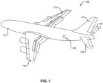
Figure 1 is a perspective view of an aircraft, according to one or more examples of the present disclosure; -
Figure 2 is a flow diagram depicting multiple steps of a method of reinforcing a surface of a vehicle, using schematic cross-sectional representations of the vehicle and reinforcement part, according to one or more examples of the present disclosure; -
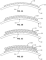
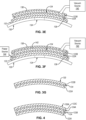
Figures 3A-3G are cross-sectional side views schematically illustrating respective steps of a method of making a reinforcement part, according to one or more examples of the present disclosure; -
Figure 4 is a cross-sectional side view of a reinforcement part, according to one or more examples of the present disclosure; -
Figure 5 is a cross-sectional side view of a reinforcement part, according to one or more examples of the present disclosure; -
Figure 6 is a cross-sectional side view of a reinforcement part, according to one or more examples of the present disclosure; -
Figure 7 is a cross-sectional side view of a reinforcement part, according to one or more examples of the present disclosure; -
Figure 8 is a cross-sectional side view of a reinforcement part, according to one or more examples of the present disclosure; -
Figures 9A-9D are cross-sectional side views schematically illustrating respective steps of a method of making a reinforcement part, according to one or more examples of the present disclosure; -
Figure 10 is a cross-sectional side view of a reinforcement part formed on a surface of a vehicle having multiple contours, according to one or more examples of the present disclosure; -
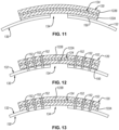
Figure 11 is a cross-sectional side view of a reinforcement part attached to the surface of a vehicle using a first method, according to one or more examples of the present disclosure; -
Figure 12 is a cross-sectional side view of a reinforcement part attached to the surface of a vehicle using a second method, according to one or more examples of the present disclosure; -
Figure 13 is a cross-sectional side view of a reinforcement part attached to the surface of a vehicle using a third method, according to one or more examples of the present disclosure; -
Figure 14 is a cross-sectional side view of a reinforcement part attached to the surface of a vehicle using a fourth method, according to one or more examples of the present disclosure; and -
Figure 15 is a schematic flow chart of a method of making a reinforcement part and reinforcing a vehicle, according to one or more examples of the present disclosure. - Reference throughout this specification to "one example," "an example," or similar language means that a particular feature, structure, or characteristic described in connection with the example is included in at least one example of the present disclosure. Appearances of the phrases "in one example," "in an example," and similar language throughout this specification may, but do not necessarily, all refer to the same example. Similarly, the use of the term "implementation" means an implementation having a particular feature, structure, or characteristic described in connection with one or more examples of the present disclosure, however, absent an express correlation to indicate otherwise, an implementation may be associated with one or more examples.
- The present disclosure includes multiple examples that overcome the shortcomings of conventional methods of reinforcing a surface of a vehicle by using the surface of the vehicle as a tooling or molding surface to form a reinforcement part that is separately attached to the surface. In this manner, the matching of the contour of the reinforcement part and the surface of the vehicle is ensured without the need for auxiliary shaping tools, such as English Wheels or molds, and the associated trial-and-error shaping methods. The reinforcement part can be formed using the damaged surface (or the surface in need of reinforcement) onto which the reinforcement part is to be attached. Alternatively, the reinforcement part can be formed using an un-damaged surface that has a contour that matches that of the damaged surface. By using the surface of the vehicle as a tooling surface, reinforcement parts can be made in a timely and efficient manner without the need for separate tooling and post-forming heat treatment.
- Referring to
Figure 1 , one example of a vehicle is shown. The vehicle illustrated inFigure 1 is anaircraft 100, which is representative of any of various types of aircraft, such as commercial aircraft used for the transportation of passengers, military aircraft for military operations, personal aircraft, fighter jets, and the like. Moreover, although an aircraft is depicted in the illustrated examples, in other examples, other types of vehicles can be used (e.g., helicopter, boat, spacecraft, automobile, etc.). - The depicted
aircraft 100 includes a body 112 (e.g., fuselage), a pair ofwings 114 coupled to and extending from thebody 112, avertical stabilizer 116 coupled to thebody 112, and a pair ofhorizontal stabilizers 118 coupled to thebody 112 and/or thevertical stabilizer 116. As depicted, theaircraft 100 represents a passenger airplane. Any of various parts, such as part 130 (see, e.g.,Figure 2 ), of theaircraft 100 include a surface that may be damaged or otherwise require reinforcement. As used herein, reinforcement mean repair or strengthening. Accordingly, a reinforcement part can mean a repair part or a strengthening part and a reinforcing method can mean a repair or strengthening method. In one example, thepart 130 is thebody 112 of theaircraft 100 and asurface 132 of the part 130 (see, e.g.,Figure 2 ) is an outer skin of thebody 112. Accordingly, in some examples, thesurface 132 of thepart 130 is an exterior surface of the vehicle. For example, thesurface 132 of thepart 130 can be an exterior surface or skin of thewings 114, thevertical stabilizer 116, and/or thehorizontal stabilizers 118. - The
surface 132 of thepart 130 can be made from any of various materials, such as a metallic material (e.g., aluminum alloy or steel alloy), or a composite material, such as a carbon-fiber or glass-fiber reinforced polymeric material. Thepart 130 can have a laminated construction. Moreover, thepart 130 has a thickness defined as a distance between thesurface 132 and an opposite surface of thepart 130. - Referring to
Figures 1 and2 , the present disclosure presents methods of making areinforcement part 120, using thesurface 132 of thepart 130 of the vehicle as a tooling surface, and subsequently attaching thereinforcement part 120 to thesurface 132 ofvehicle 100. As shown inFigure 2 , in one example, thereinforcement part 120 is formed on thesurface 132 of thepart 130. In some examples, thereinforcement part 120 is formed overdamage 134 in thesurface 132 of thepart 130, removed from thesurface 132, and then attached back onto thesurface 132 over thedamage 134. However, in alternative examples, thereinforcement part 120 is formed on a portion of thesurface 132 of thepart 130 that does not have thedamage 134, removed from that portion of thesurface 132, and then attached onto the portion of thesurface 132 that has thedamage 134. The attachment of thereinforcement part 120 to thesurface 132 is performed separately and by a different process than the formation of thereinforcement part 120 on thesurface 132. - The
reinforcement part 120 formed on thesurface 132 has, at least, a firstmetallic layer 122A, a secondmetallic layer 122B, and acurable bonding layer 124 that is interposed between the firstmetallic layer 122A and the secondmetallic layer 122B. Thecurable bonding layer 124 bonds the firstmetallic layer 122A and the secondmetallic layer 122B together to create a laminated structure. The laminated construction of thereinforcement part 120 helps to reduce fatigue, by absorbing and distributing microcrack energy. Additionally, the potential for corrosion is reduced by the isolation provided by the interleaved bonding layers, which limit corrosion to the outermost layers of thereinforcement part 120. - Referring to
Figure 15 , amethod 200 of making a reinforcement part and reinforcing a surface of a vehicle is shown. Themethod 200 includes (block 202) applying arelease film 136 directly onto thesurface 132 of the vehicle (e.g., thepart 130 of the aircraft 100) so that therelease film 136 conforms to a shape of thesurface 132. As shown inFigure 3A , therelease film 136 is applied directly onto thesurface 132 of thepart 130 and takes the same shape as thesurface 132. In the illustrated example the shape of thesurface 132, and thus therelease film 136 is a convex shape, but could be any of various non-planar shapes, such as a concave shape or a complex contoured shape with multiple inflection points (see, e.g.,Figure 10 ) for example. However, in other examples, thesurface 132 can have a planar shape without departing from the essence of the present disclosure. Therelease film 136 can be any of various non-stick release films or liners configured to reduce adhesion or sticking between two parts, such as for example, siliconized films, polyester films, Teflon sheets, polytetrafluoroethylene (PTFE) sheets, and the like. Moreover, therelease film 136 is deformable or flexible, which enables therelease film 136 to take the same shape as thesurface 132. - The
release film 136 is directly applied onto thesurface 132 over damage 134 (e.g., cracking) in thesurface 132 in some examples. In these examples, thedamage 134, if passing entirely through the thickness of thepart 130, may need to be plugged to enable negative pressure generation, as described in more detail below. However, in other examples, therelease film 136 is directly applied onto thesurface 132 adjacent to thedamage 134, so that therelease film 136 is not applied over thedamage 134. In these other examples, thedamage 134 need not be plugged, even if passing entirely through the thickness of thepart 130. - The
method 200 also includes (block 204) applying the firstmetallic layer 122A directly or indirectly onto therelease film 136 so that the firstmetallic layer 122A conforms to the shape of thesurface 132. As used herein, directly applying a given layer onto another object means no other layer is interposed between the given layer and the object. In contrast, indirectly applying a given layer onto another object means another layer can be interposed between the given layer and the object. Referring toFigure 3B , in some examples, the firstmetallic layer 122A is applied directly onto therelease film 136 and takes the same shape as therelease film 136, thus taking the same shape as thesurface 132. The coverage of therelease film 136 over thesurface 132 is at least as large as the coverage of the firstmetallic layer 122A over therelease film 136 to ensure therelease film 136 is interposed between an entirety of the firstmetallic layer 122A and thesurface 132. The firstmetallic layer 122A is deformable or flexible, which enables the firstmetallic layer 122A to take the same shape as thesurface 132. The relatively small thickness of the firstmetallic layer 122A enables the deformability of the firstmetallic layer 122A. In some examples, the firstmetallic layer 122A has a thickness that is between, and inclusive of, 0.0254 cm and 0.1016 cm (0.01 inches and 0.04 inches). In one example, the firstmetallic layer 122A is made of an aluminum alloy or a titanium alloy and has a thickness between, and inclusive of, 0.0254 cm and 0.0762 cm (0.01 inches and 0.03 inches) (e.g., 0.0508 cm or 0.02 inches). - The
method 200 also includes (block 206) applying thecurable bonding layer 124 directly onto the firstmetallic layer 122A so that thecurable bonding layer 124 conforms to the shape of thesurface 132. Referring toFigure 3C , in some examples, thecurable bonding layer 124 is applied directly onto the firstmetallic layer 122A and takes the same shape as the firstmetallic layer 122A, thus taking the same shape as thesurface 132. Thecurable bonding layer 124, prior to curing, is deformable or flexible, which enables thecurable bonding layer 124 to take the same shape as thesurface 132. In some examples, the thickness of thecurable bonding layer 124 is less than the thickness of the firstmetallic layer 122A. In one example, thecurable bonding layer 124 is made of a curable bonding material, such as an adhesive, a resin, an epoxy, and the like. The curable bonding material can be curable at any of various temperatures, such as room temperature (e.g., between 20°C and 24.4°C (68°F and 76°F)), or an elevated temperature above room temperature. As explained in more detail below, thecurable bonding layer 124 is a non-fibrousadhesive layer 146 in some examples (see, e.g.,Figure 6 ), a fiber-reinforcedpolymeric layer 148 in other examples (see, e.g.,Figure 7 ), or a combination of non-fibrousadhesive layers 146 and a fiber-reinforced polymeric layer 148 (see, e.g.,Figure 8 ). - When the
curable bonding layer 124 is or consists of the non-fibrousadhesive layer 146, the non-fibrousadhesive layer 146 can be applied onto the firstmetallic layer 122A using any of various application techniques. When applied, the material of the non-fibrousadhesive layer 146 can be in a glutinous or flowable state and applied by dispensing the non-fibrousadhesive layer 146 onto the firstmetallic layer 122A. In other examples, the non-fibrousadhesive layer 146 can be a solid, nonflowable, sheet that is placed onto the firstmetallic layer 122A. - When the
curable bonding layer 124 is a fiber-reinforcedpolymeric layer 148 made of prepreg material, the prepreg material, which can be a sheet of prepreg material, is placed or laid up onto the firstmetallic layer 122A. The prepreg material can be a fiberglass prepreg or carbon-fiber prepreg. Referring toFigure 8 , when thecurable bonding layer 124 has a laminate construction made of a combination of non-fibrousadhesive layers 146 and a fiber-reinforcedpolymeric layer 148, thecurable bonding layer 124 is applied onto the firstmetallic layer 122A by applying a non-fibrous adhesive layer 146 (e.g., a first non-fibrous adhesive layer) onto the firstmetallic layer 122A, applying a fiber-reinforcedpolymeric layer 148 onto the non-fibrousadhesive layer 146, and applying a non-fibrous adhesive layer 146 (e.g., a second non-fibrous adhesive layer) onto the fiber-reinforcedpolymeric layer 148. In certain examples, when the fiber-reinforcedpolymeric layer 148 is formed using adry fiber sheet 154 infused with liquid resin (as described below), thecurable bonding layer 124 can have a laminate construction made of thedry fiber sheet 154, infused with resin (i.e., the resininfused dry fiber sheet) interposed or sandwiched between two non-fibrous adhesive layers 146. - The
method 200 further includes (block 208) applying the secondmetallic layer 122B directly onto thecurable bonding layer 124 so that the secondmetallic layer 122B conforms to the shape of thesurface 132. Referring toFigure 3D , in some examples, the secondmetallic layer 122B is applied directly onto thecurable bonding layer 124 and takes the same shape as thecurable bonding layer 124, thus taking the same shape as thesurface 132. In some examples, the secondmetallic layer 122B is configured and is made of the same material as the firstmetallic layer 122A. Accordingly, the secondmetallic layer 122B is deformable or flexible, which enables therelease film 136 to take the same shape as thesurface 132. - The
method 200 additionally includes (block 210) applying pressure to the firstmetallic layer 122A, thecurable bonding layer 124, and the secondmetallic layer 122B so that the firstmetallic layer 122A, thecurable bonding layer 124, and the secondmetallic layer 122B are compressed against thesurface 132. Referring toFigure 3E , in one example, the pressure is applied to the layers via negative pressure created within avacuum bag 138 sealed to thesurface 132 over the layers. Thevacuum bag 138 can be sealed to thesurface 132 via any of various sealing techniques, such as tape, adhesive, etc. An interior cavity is defined between thevacuum bag 138 and the layers. Thevacuum bag 138 includes an outlet that fluidically couples the interior cavity with avacuum source 140, such as via a conduit or hose. When thevacuum source 140, which can include a vacuum device, is activated, the pressure within the interior cavity is reduced until thevacuum bag 138 applies a uniform pressure to the firstmetallic layer 122A, thecurable bonding layer 124, and the secondmetallic layer 122B, which compresses the layers against thesurface 132. Although the application of negative pressure is illustrated herein, in alternative examples, the pressure applied to the layers can be positive pressure, such as pressure applied via pressurized cylinders or actuators. - The
method 200 further includes (block 212) curing thecurable bonding layer 124 when pressure is applied to the curable bonding layer 124 (and the firstmetallic layer 122A and the secondmetallic layer 122B). In some examples, based on the type of curable material of thecurable bonding layer 124, thecurable bonding layer 124 is cured at room temperature. For example, thecurable bonding layer 124 can be a liquid resin that is cured when left at room temperature for a predetermined period of time. However, in other examples, based on the type of curable material of thecurable bonding layer 124, thecurable bonding layer 124 is cured by heating the curable material. For example, the curable material can be a solid resin of a prepreg sheet that is cured when heated to a cure temperature of the solid resin for a predetermined period of time. Referring toFigure 3F , in some examples where the curable material of thecurable bonding layer 124 is cured by heating the curable material, the curable material is heated by applying aheating blanket 142 over the firstmetallic layer 122A, thecurable bonding layer 124, and the secondmetallic layer 122B and activating the heating blanket 142 (by providing power from a power source 144) to generate heat. The heat from theheating blanket 142 is transmitted into the layers, including thecurable bonding layer 124, to cure thecurable bonding layer 124. As shown inFigure 3F , in some examples, thevacuum bag 138 is applied over theheating blanket 142 after theheating blanket 142 is applied onto the firstmetallic layer 122A, thecurable bonding layer 124, and the secondmetallic layer 122B. Accordingly, in such examples, theheating blanket 142 is located within the interior cavity defined by thevacuum bag 138 and is compressed, along with the layers, when the pressure within interior cavity is reduced. - The
method 200 also includes (block 214) removing the firstmetallic layer 122A, thecurable bonding layer 124, and the secondmetallic layer 122B from thesurface 132 after thecurable bonding layer 124 is cured. After thecurable bonding layer 124 is cured, the firstmetallic layer 122A, thecurable bonding layer 124, and the secondmetallic layer 122B form thereinforcement part 120. Accordingly, removing the firstmetallic layer 122A, the curable bonding layer 124 (after being cured), and the secondmetallic layer 122B means removing thereinforcement part 120 from thesurface 132. In other words, thereinforcement part 120 is formed in situ on thesurface 132 of thepart 130 of the vehicle before being removed from thesurface 132. One example of thefinished reinforcement part 120 is shown inFigure 3G . It is recognized that removing thereinforcement part 120 from thesurface 132 implies thereinforcement part 120 is removed from therelease film 136. Subsequently, therelease film 136 can be removed from thesurface 132 as well and reused or discarded. Additional steps of the method can include trimming thereinforcement part 120 down to an appropriate size conducive to attachment back onto thesurface 132 over thedamage 134. - Although the
reinforcement part 120 shown inFigure 3G includes only two metallic layers and one curable bonding layer between the two metallic layers, in other examples, thereinforcement part 120 can include one or more additional curable bonding layers and metallic layers. In other words, thereinforcement part 120 can have any number of alternating metallic layers and curable bonding layers. For example, as shown inFigure 4 , asecond reinforcement part 120A includes a secondcurable bonding layer 124A and a thirdmetallic layer 122C, where the secondcurable bonding layer 124A is interposed between the secondmetallic layer 122B and the thirdmetallic layer 122C. As another example, as shown inFigure 5 , a third reinforcement part 120B includes a thirdcurable bonding layer 124B and a fourthmetallic layer 122D, where the thirdcurable bonding layer 124B is interposed between the thirdmetallic layer 122C and the fourthmetallic layer 122D. Moreover, the size and/or shape of one or more of the metallic layers and curable bonding layers can be different that of another one or more of the metallic layers and curable bonding layers. For example, a reinforcement part can be a repeating pattern of metallic layers and curable bonding layers where at least one of the metallic layers and at least one of the curable bonding layers have a smaller size relative to the layers underneath. For example, as shown inFigure 5 , the firstmetallic layer 122A, thecurable bonding layer 124, and the secondmetallic layer 122B have a first width W1, and the secondcurable bonding layer 124A, the thirdmetallic layer 122C, the thirdcurable bonding layer 124B, and the fourthmetallic layer 122D have a second width W2 that is less than the first width W 1. - Referring to
Figures 9A-9D , in some examples, thecurable bonding layer 124 includes adry fiber sheet 154 that is infused with liquid resin. In such examples, the step of applying thecurable bonding layer 124 includes applying thedry fiber sheet 154 directly onto the firstmetallic layer 122A and infusing liquid resin into thedry fiber sheet 154 after it's applied onto the firstmetallic layer 122A. In certain examples, as shown inFigure 9A , a base or secondcurable bonding layer 124A is applied directly onto therelease film 136 and the firstmetallic layer 122A is applied directly onto the secondcurable bonding layer 124A, such that the firstmetallic layer 122A is applied indirectly onto therelease film 136. The secondcurable bonding layer 124A can include adry fiber sheet 154 that is infused with liquid resin and can be applied in the same manner as described above. The liquid resin is supplied from a resin source 158, which can be infused into thedry fiber sheet 154 manually or automatically. - Referring to
Figure 9C , to promote uniform infusion of the resin throughout thedry fiber sheet 154, in some examples, the step of infusing the liquid resin includes applying avacuum bag 160 over the firstmetallic layer 122A, the fiber-reinforced polymeric layer 148 (e.g., the liquid-resin infused dry fiber sheet), the secondmetallic layer 122B, and, optionally, the secondcurable bonding layer 124A, and sealing thevacuum bag 160 to thesurface 132. When sealed, thevacuum bag 160 defines a cavity with thesurface 132 that houses the firstmetallic layer 122A, the fiber-reinforced polymeric layer, the secondmetallic layer 122B, and, optionally, the base or secondcurable bonding layer 124A. The pressure within the cavity is reduced, such as via asecond vacuum source 141, so that vacuum conditions are created within the cavity and thevacuum bag 160 applies a uniform pressure to the firstmetallic layer 122A, the fiber-reinforcedpolymeric layer 148, the secondmetallic layer 122B, and, optionally, the secondcurable bonding layer 124A. The uniform pressure helps to evenly distribute the resin within thedry fiber sheet 154 of the fiber-reinforcedpolymeric layer 148 and optionally the secondcurable bonding layer 124A. - Referring to
Figure 9D , in some examples where thecurable bonding layer 124 includes adry fiber sheet 154 infused with liquid resin, the liquid resin is cured by heating the curable material with aheating blanket 142 applied over thevacuum bag 160. Additionally, anothervacuum bag 138 is applied over theheating blanket 142, and thus over thevacuum bag 160. Accordingly, in such examples, theheating blanket 142 and thevacuum bag 160 is located within the interior cavity defined by thevacuum bag 138 and are compressed, along with the layers, when the pressure within interior cavity of thevacuum bag 138 is reduced. In this manner, a dual vacuum bag solution can be used to both infuse a dry fiber sheet with resin and to promote curing of the resin. - In certain examples where the
curable bonding layer 124 includes a curable material that is curable at room temperature, the cure at room temperature is an initial cure and the method further includes an additional or final curing of thecurable bonding layer 124 after thereinforcement part 120 is removed from thesurface 132. The final curing of thecurable bonding layer 124 can include raising the temperature of thecurable bonding layer 124 to some predetermined temperature associated with an increased strength of thecurable bonding layer 124. - Referring again to
Figure 15 , themethod 200 additionally includes (block 216) attaching thereinforcement part 120 to thesurface 132 after thereinforcement part 120 is removed from thesurface 132 following formation of thereinforcement part 120 on thesurface 132. Referring toFigures 11-13 , in some examples, thereinforcement part 120 is attached to thesurface 132 over (e.g., covering) thedamage 134 to help reinforce (e.g., reduce propagation of thedamage 134 to) thesurface 132. However, in other examples, such as shown inFigure 14 , thereinforcement part 120 is attached to thesurface 132 adjacent afeature 166 of (or damage to) thesurface 132 to help reinforce thefeature 166 by building up the gauge around the feature or damage. Thefeature 166 can be any of various features, such as a hole, a build-up around a hole, and the like. In such examples, thereinforcement part 120 can be formed with anopening 168 that corresponds with thefeature 166, such that thefeature 166 is accessible through thereinforcement part 120. - The
reinforcement part 120 can be attached to thesurface 132 of thepart 130 in several ways. In a first example, shown inFigures 11 and14 , thereinforcement part 120 is secondarily bonded directly to thesurface 132 with an adhesive 150 and without any fasteners. According to a second example, shown inFigure 12 , thereinforcement part 120 is secondarily bonded directly to thesurface 132 with an adhesive 150 and thereinforcement part 120 is fastened to thesurface 132, such as with bolts orfasteners 152. Thefasteners 152 can help take on loads in the event the bond created by the adhesive 150 weakens or fails. In a third example, shown inFigure 13 , thereinforcement part 120 is fastened to thesurface 132 without an adhesive. - As presented above, the
reinforcement part 120 is formed on thesurface 132, using thesurface 132 as a tooling surface, removing thereinforcement part 120 from thesurface 132, and subsequently attaching thereinforcement part 120 onto thesurface 132. The location on or the portion of thesurface 132 to which thereinforcement part 120 is attached is associated with a damaged portion of the surface 132 (i.e., a location on or the portion of thesurface 132 that has the damage 134). In other words, thereinforcement part 120 is attached to a damaged portion of thesurface 132 so that thereinforcement part 120 is either directly adjacent to (e.g., around) thedamage 134 or is over (e.g., covering) thedamage 134. - However, the portion of the
surface 132 used as the tooling surface to form thereinforcement part 120 can be either the damaged portion or an undamaged portion of the surface 132 (i.e., a location on or the portion of thesurface 132 that does not have damage, but does have a contour that is the same as the contour of the damaged portion of the surface 132). In one example, thereinforcement part 120 is formed on an undamaged portion of thesurface 132 that shares similar contour characteristics as the damaged portion. For example, the undamaged portion can be a portion contiguous with the damaged portion or adjacent to the damaged portion (e.g., over, under, or to the side of the damaged portion. According to some implementations, the undamaged portion of thesurface 132, on which thereinforcement part 120 is formed, is the portion of thesurface 132 above or below the damaged portion at the same axial location along the body of the vehicle because the contour of the surface at the same axial location can be the same along an entire circumference of the vehicle. Because the contour characteristics of the undamaged portion and the damaged portion are similar or the same, the contour of thereinforcement part 120, when formed on the undamaged portion, promotes a mating engagement with the damaged portion when attached to the damaged portion. - According to another example, the
reinforcement part 120 is formed on the damaged portion of thesurface 132. In these examples, thereinforcement part 120 is removed from the damaged portion, to allow removal of therelease film 136, and is then attached onto the same damaged portion. Forming thereinforcement part 120 on the same surface onto which thereinforcement part 120 will be attached ensures a mating engagement with the damage portion of thesurface 132. - In the above description, certain terms may be used such as "up," "down," "upper," "lower," "horizontal," "vertical," "left," "right," "over," "under" and the like. These terms are used, where applicable, to provide some clarity of description when dealing with relative relationships. But, these terms are not intended to imply absolute relationships, positions, and/or orientations. For example, with respect to an object, an "upper" surface can become a "lower" surface simply by turning the object over. Nevertheless, it is still the same object. Further, the terms "including," "comprising," "having," and variations thereof mean "including but not limited to" unless expressly specified otherwise. An enumerated listing of items does not imply that any or all of the items are mutually exclusive and/or mutually inclusive, unless expressly specified otherwise. The terms "a," "an," and "the" also refer to "one or more" unless expressly specified otherwise. Further, the term "plurality" can be defined as "at least two." Moreover, unless otherwise noted, as defined herein a plurality of particular features does not necessarily mean every particular feature of an entire set or class of the particular features.
- Additionally, instances in this specification where one element is "coupled" to another element can include direct and indirect coupling. Direct coupling can be defined as one element coupled to and in some contact with another element. Indirect coupling can be defined as coupling between two elements not in direct contact with each other, but having one or more additional elements between the coupled elements. Further, as used herein, securing one element to another element can include direct securing and indirect securing. Additionally, as used herein, "adjacent" does not necessarily denote contact. For example, one element can be adjacent another element without being in contact with that element.
- As used herein, the phrase "at least one of", when used with a list of items, means different combinations of one or more of the listed items may be used and only one of the items in the list may be needed. The item may be a particular object, thing, or category. In other words, "at least one of' means any combination of items or number of items may be used from the list, but not all of the items in the list may be required. For example, "at least one of item A, item B, and item C" may mean item A; item A and item B; item B; item A, item B, and item C; or item B and item C. In some cases, "at least one of item A, item B, and item C" may mean, for example, without limitation, two of item A, one of item B, and ten of item C; four of item B and seven of item C; or some other suitable combination.
- Unless otherwise indicated, the terms "first," "second," etc. are used herein merely as labels, and are not intended to impose ordinal, positional, or hierarchical requirements on the items to which these terms refer. Moreover, reference to, e.g., a "second" item does not require or preclude the existence of, e.g., a "first" or lower-numbered item, and/or, e.g., a "third" or higher-numbered item.
- As used herein, a system, apparatus, structure, article, element, component, or hardware "configured to" perform a specified function is indeed capable of performing the specified function without any alteration, rather than merely having potential to perform the specified function after further modification. In other words, the system, apparatus, structure, article, element, component, or hardware "configured to" perform a specified function is specifically selected, created, implemented, utilized, programmed, and/or designed for the purpose of performing the specified function. As used herein, "configured to" denotes existing characteristics of a system, apparatus, structure, article, element, component, or hardware which enable the system, apparatus, structure, article, element, component, or hardware to perform the specified function without further modification. For purposes of this disclosure, a system, apparatus, structure, article, element, component, or hardware described as being "configured to" perform a particular function may additionally or alternatively be described as being "adapted to" and/or as being "operative to" perform that function.
- The schematic flow chart diagrams included herein are generally set forth as logical flow chart diagrams. As such, the depicted order and labeled steps are indicative of one example of the presented method. Other steps and methods may be conceived that are equivalent in function, logic, or effect to one or more steps, or portions thereof, of the illustrated method. Additionally, the format and symbols employed are provided to explain the logical steps of the method and are understood not to limit the scope of the method. Although various arrow types and line types may be employed in the flow chart diagrams, they are understood not to limit the scope of the corresponding method. Indeed, some arrows or other connectors may be used to indicate only the logical flow of the method. For instance, an arrow may indicate a waiting or monitoring period of unspecified duration between enumerated steps of the depicted method. Additionally, the order in which a particular method occurs may or may not strictly adhere to the order of the corresponding steps shown.
- Further, the present disclosure comprises aspects according to the following clauses:
- Clause 1. A method of making a reinforcement part for a vehicle, the method comprising:
- applying a release film directly onto a surface of the vehicle so that the release film conforms to a shape of the surface;
- applying a first metallic layer directly or indirectly onto the release film so that the first metallic layer conforms to the shape of the surface;
- applying a curable bonding layer directly onto the first metallic layer so that the curable bonding layer conforms to the shape of the surface;
- applying a second metallic layer directly onto the curable bonding layer so that the curable bonding layer is interposed between the first metallic layer and the second metallic layer, and so that the second metallic layer conforms to the shape of the surface;
- applying pressure to the first metallic layer, the curable bonding layer, and the second metallic layer so that the first metallic layer, the curable bonding layer,
- and the second metallic layer are compressed against the surface;
- curing the curable bonding layer when pressure is applied to the curable bonding layer to form the reinforcement part; and
- after curing the curable bonding layer, removing the reinforcement part from the surface.
- Clause 2. The method according to clause 1, wherein the curable bonding layer comprises a fiber-reinforced polymeric layer.
- Clause 3. The method according to clause 2, wherein:
- the fiber-reinforced polymeric layer comprises a prepreg material; and
- curing the curable bonding layer comprises heating the prepreg material.
- Clause 4. The method according to clause 3, wherein heating the prepreg material comprises applying a heating blanket over the first metallic layer, the fiber-reinforced polymeric layer, and the second metallic layer and activating the heating blanket.
- Clause 5. The method according to clause 2, wherein:
- the curable bonding layer comprises a dry fiber sheet infused with liquid resin; and
- applying the curable bonding layer comprises applying the dry fiber sheet directly onto the first metallic layer and infusing liquid resin into the dry fiber sheet when the dry fiber sheet is applied onto the first metallic layer.
- Clause 6. The method according to clause 5, wherein the liquid resin is cured at room temperature.
- Clause 7. The method according to clause 6, further comprising curing the fiber-reinforced polymer layer at a temperature greater than room temperature after the reinforcement part is removed from the surface.
- Clause 8. The method according to clause 5, wherein infusing the liquid resin into the dry fiber sheet comprises:
- applying a vacuum bag over the first metallic layer, the fiber-reinforced polymeric layer, and the second metallic layer;
- sealing the vacuum bag to the surface so that the first metallic layer, the fiber-reinforced polymeric layer, and the second metallic layer are sealed within a cavity defined between the vacuum bag and the surface; and
- reducing the pressure within the cavity.
- Clause 9. The method according to clause 8, wherein:
- curing the curable bonding layer comprises applying a heating blanket over the vacuum bag, the first metallic layer, the fiber-reinforced polymeric layer, and the second metallic layer; and
- applying pressure to the first metallic layer, the fiber-reinforced polymeric layer, and the second metallic layer comprises:
- applying a second vacuum bag over the heating blanket, the vacuum bag, the first metallic layer, the fiber-reinforced polymeric layer, and the second metallic layer;
- sealing the second vacuum bag to the surface so that the heating blanket, the vacuum bag, the first metallic layer, the fiber-reinforced polymeric layer, and the second metallic layer are sealed within a second cavity defined between the second vacuum bag and the surface; and
- reducing the pressure within the second cavity.
- Clause 10. The method according to clause 1, wherein applying pressure to the first metallic layer, the curable bonding layer, and the second metallic layer comprises:
- applying a vacuum bag over the first metallic layer, the curable bonding layer, and the second metallic layer;
- sealing the vacuum bag to the surface so that the first metallic layer, the curable bonding layer, and the second metallic layer are sealed within a cavity defined between the vacuum bag and the surface; and
- reducing the pressure within the cavity.
- Clause 11. The method according to clause 1, wherein the curable bonding layer consists of a non-fibrous adhesive layer.
- Clause 12. The method according to clause 1, wherein the curable bonding layer comprises:
- a first non-fibrous adhesive layer;
- a second non-fibrous adhesive layer; and
- a fiber-reinforced polymeric layer interposed between the first non-fibrous adhesive layer and the second non-fibrous adhesive layer.
- Clause 13. The method according to clause 1, wherein each one of the first metallic layer and the second metallic layer has a thickness between, and inclusive of, 0.0254 cm and 0.1016 cm (0.01 inches and 0.04 inches).
- 14. The method according to clause 1, wherein the shape of the surface, to which the release film, the first metallic layer, the curable bonding layer, and the second metallic layer is conformed, is non-planar.
- 15. The method according to clause 1, wherein:
- the vehicle is an aircraft; and
- the surface is an exterior surface of a skin of the aircraft.
- Clause 16. The method according to clause 1, wherein one of:
- the first metallic layer is applied directly onto the release film; or
- the method further comprises applying a second curable bonding layer directly onto the release film so that the second curable bonding layer conforms to the shape of the surface, and the first metallic layer is applied directly onto the second curable bonding layer.
- Clause 17. A method of reinforcing a vehicle, the method comprising:
- applying a release film directly onto a surface of the vehicle so that the release film conforms to a shape of the surface;
- applying a first metallic layer directly or indirectly onto the release film so that the first metallic layer conforms to the shape of the surface;
- applying a curable bonding layer directly onto the first metallic layer so that the curable bonding layer conforms to the shape of the surface;
- applying a second metallic layer directly onto the curable bonding layer so that the curable bonding layer is interposed between the first metallic layer and the second metallic layer, and so that the second metallic layer conforms to the shape of the surface;
- applying pressure to the first metallic layer, the curable bonding layer, and the second metallic layer so that the first metallic layer, the curable bonding layer, and the second metallic layer are compressed against the surface;
- curing the curable bonding layer when pressure is applied to the curable bonding layer to form a reinforcement part comprising the first metallic layer, the curable bonding layer, and the second metallic layer;
- after curing the curable bonding layer, removing the reinforcement part from the surface and removing the release film from the surface; and
- after removing the reinforcement part and the release film from the surface, attaching the reinforcement part to the surface.
- Clause 18. The method according to clause 17, wherein:
- the release film is applied directly onto a first portion of the surface over damage to or adjacent a feature of the first portion of the surface;
- the first metallic layer, the curable bonding layer, and the second metallic layer conform to the shape of the first portion of the surface; and
- the reinforcement part is attached to the first portion of the surface over the damage to or adjacent the feature of the first portion of the surface.
- Clause 19. The method according to clause 17, wherein:
- the release film is applied directly onto a first portion of the surface;
- the first metallic layer, the curable bonding layer, and the second metallic layer conform to the shape of the first portion of the surface;
- the reinforcement part is attached to a second portion of the surface over damage to or adjacent a feature of a second portion of the surface that is spaced from the first portion of the surface; and
- the first portion of the surface has a contour that matches a contour of the second portion of the surface.
- Clause 20. The method according to clause 17, wherein attaching the reinforcement part to the surface comprises bonding the reinforcement part to the surface.
- Clause 21. The method according to clause 20, wherein attaching the reinforcement part to the surface further comprises bolting the reinforcement part to the surface.
- Clause 22. The method according to clause 17, wherein attaching the reinforcement part to the surface comprises bolting the reinforcement part to the surface.
Claims (15)
- A method of making a reinforcement part (120) for a vehicle (100), the method comprising:applying a release film (136) directly onto a planar or non-planar surface (132) of the vehicle (100) so that the release film (136) conforms to a shape of the surface (132);applying a first metallic layer (122A) directly or indirectly onto the release film (136) so that the first metallic layer (122A) conforms to the shape of the surface (132);applying a curable bonding layer (124) directly onto the first metallic layer (122A) so that the curable bonding layer (124) conforms to the shape of the surface (132);applying a second metallic layer (122B) directly onto the curable bonding layer (124) so that the curable bonding layer (124) is interposed between the first metallic layer (122A) and the second metallic layer (122B), and so that the second metallic layer (122B) conforms to the shape of the surface (132);applying pressure to the first metallic layer (122A), the curable bonding layer (124), and the second metallic layer (122B) so that the first metallic layer (122A), the curable bonding layer (124), and the second metallic layer (122B) are compressed against the surface (132);curing the curable bonding layer (124) when pressure is applied to the curable bonding layer (124) to form the reinforcement part (120); andafter curing the curable bonding layer (124), removing the reinforcement part (120) from the surface (132).
- The method according to claim 1, wherein the curable bonding layer (124) comprises a fiber-reinforced polymeric layer (148), preferably a prepreg material; and curing the curable boding layer (124) comprises heating the fiber-reinforced polymeric layer (148).
- The method according to claim2, wherein heating the fiber-reinforced polymeric layer (148) comprises applying a heating blanket (142) over the first metallic layer (122A), the fiber-reinforced polymeric layer (148), and the second metallic layer (122B) and activating the heating blanket (142).
- The method according to claim 1, wherein:the curable bonding layer (124) comprises a dry fiber sheet (154) infused with liquid resin; andapplying the curable bonding layer (124) comprises applying the dry fiber sheet (154) directly onto the first metallic layer (122A) and infusing liquid resin into the dry fiber sheet (154) when the dry fiber sheet (154) is applied onto the first metallic layer (122A).
- The method according to claim 4, wherein the liquid resin is cured either at room temperature or at a temperature greater than room temperature after the reinforcement part (120) is removed from the surface (132).
- The method according to any one of claims 4- 5, wherein infusing the liquid resin into the dry fiber sheet (154) comprises:applying a first vacuum bag (160) over the first metallic layer (122A), the fiber-reinforced polymeric layer (148), and the second metallic layer (122B);sealing the first vacuum bag (160) to the surface (132) so that the first metallic layer (122A), the fiber-reinforced polymeric layer (148), and the second metallic layer (122B) are sealed within a first cavity defined between the vacuum bag (138) and the surface (132); andreducing the pressure within the first cavity.
- The method according to claim 6, wherein:curing the curable bonding layer (124) comprises applying a heating blanket (142) over the first vacuum bag (160), the first metallic layer (122A), the fiber-reinforced polymeric layer (148), and the second metallic layer (122B); andapplying pressure to the first metallic layer (122A), the fiber-reinforced polymeric layer (148), and the second metallic layer (122B) comprises:applying a second vacuum bag (138) over the heating blanket (142), the vacuum bag (160), the first metallic layer (122A), the fiber-reinforced polymeric layer (148), and the second metallic layer (122B);sealing the second vacuum bag (138) to the surface (132) so that the heating blanket (142), the vacuum bag (160), the first metallic layer (122A), the fiber-reinforced polymeric layer (148), and the second metallic layer (122B) are sealed within a second cavity defined between the second vacuum bag (138) and the surface (132); andreducing the pressure within the second cavity.
- The method according to claim 1, wherein applying pressure to the first metallic layer (122A), the curable bonding layer (124), and the second metallic layer (122B) comprises:applying a vacuum bag (138) over the first metallic layer (122A), the curable bonding layer (124), and the second metallic layer (122B);sealing the vacuum bag (138) to the surface (132) so that the first metallic layer (122A), the curable bonding layer (124), and the second metallic layer (122B) are sealed within a first cavity defined between the vacuum bag (138) and the surface (132); andreducing the pressure within the cavity.
- The method according to claim 1, wherein the curable bonding layer (124) either consists of a non-fibrous adhesive layer (146) or comprises:a first non-fibrous adhesive layer (146);a second non-fibrous adhesive layer (146); anda fiber-reinforced polymeric layer (148) interposed between the first non-fibrous adhesive layer (146) and the second non-fibrous adhesive layer (146).
- The method according to any one of the preceding claims, wherein:the vehicle (100) is an aircraft; andthe surface (132) is an exterior surface of a skin of the aircraft.
- The method according to any one of the preceding claims, further comprising applying a second curable bonding layer (124) directly onto the release film (136) so that the second curable bonding layer (124) conforms to the shape of the surface (132), and applying the first metallic layer (122A) directly onto the second curable bonding layer (124).
- A method of reinforcing a vehicle (100), comprising carrying out a method of making a reinforcement part (120) according to anyone of the preceding claims, thereby obtaining a reinforcement part (120); and:
attaching the reinforcement part (120) to the surface (132). - The method according to claim 12, wherein:the release film (136) is applied directly onto a first portion of the surface (132);the first metallic layer (122A), the curable bonding layer (124), and the second metallic layer (122B) conform to the shape of the first portion of the surface (132); andthe reinforcement part (120) is attached either to the first portion of the surface (132) over a damage to or adjacent a feature of the first portion of the surface (132), or to a second portion of the surface (132) over damage to or adjacent a feature of a second portion of the surface (132) that is spaced from the first portion of the surface (132), the first portion of the surface (132) having a contour that matches a contour of the second portion of the surface (132).
- The method according to any one of claims 12-13, wherein attaching the reinforcement part (120) to the surface (132) comprises bonding the reinforcement part (120) to the surface (132).
- The method according to any one of claims 12-14, wherein attaching the reinforcement part (120) to the surface (132) further comprises bolting the reinforcement part (120) to the surface (132).
Applications Claiming Priority (1)
| Application Number | Priority Date | Filing Date | Title |
|---|---|---|---|
| US18/455,532 US12358273B2 (en) | 2023-08-24 | 2023-08-24 | Methods of making a reinforcement part and reinforcing a vehicle |
Publications (2)
| Publication Number | Publication Date |
|---|---|
| EP4512604A1 true EP4512604A1 (en) | 2025-02-26 |
| EP4512604B1 EP4512604B1 (en) | 2026-03-11 |
Family
ID=91967019
Family Applications (1)
| Application Number | Title | Priority Date | Filing Date |
|---|---|---|---|
| EP24190361.6A Active EP4512604B1 (en) | 2023-08-24 | 2024-07-23 | Methods of making a reinforcement part and reinforcing a vehicle |
Country Status (3)
| Country | Link |
|---|---|
| US (1) | US12358273B2 (en) |
| EP (1) | EP4512604B1 (en) |
| CN (1) | CN119502399A (en) |
Cited By (1)
| Publication number | Priority date | Publication date | Assignee | Title |
|---|---|---|---|---|
| US20250065616A1 (en) * | 2023-08-24 | 2025-02-27 | The Boeing Company | Methods of making a reinforcement part and reinforcing a vehicle |
Citations (4)
| Publication number | Priority date | Publication date | Assignee | Title |
|---|---|---|---|---|
| EP1321283A1 (en) * | 2001-12-18 | 2003-06-25 | Fokker Aerostructures B.V. | Method for the production of a laminate and bent product consisting of laminate |
| WO2012154544A2 (en) * | 2011-05-06 | 2012-11-15 | Purdue Research Foundation | Method and system of vacuum assisted resin transfer molding for repair of composite materials and structure |
| EP2873620A1 (en) * | 2013-11-14 | 2015-05-20 | Airbus Operations GmbH | Repair method for fuselage components of aircraft or spacecraft |
| EP4169702A1 (en) * | 2021-10-25 | 2023-04-26 | Airbus SAS | Fibre metal laminate part, aircraft having a fibre metal laminate part, and method for manufacturing a fibre metal laminate part |
Family Cites Families (2)
| Publication number | Priority date | Publication date | Assignee | Title |
|---|---|---|---|---|
| US11400657B2 (en) | 2017-10-02 | 2022-08-02 | The Boeing Company | Methods of fabrication of composite repair parts and related kits |
| US12358273B2 (en) * | 2023-08-24 | 2025-07-15 | The Boeing Company | Methods of making a reinforcement part and reinforcing a vehicle |
-
2023
- 2023-08-24 US US18/455,532 patent/US12358273B2/en active Active
-
2024
- 2024-07-23 EP EP24190361.6A patent/EP4512604B1/en active Active
- 2024-07-24 CN CN202410996266.XA patent/CN119502399A/en active Pending
Patent Citations (4)
| Publication number | Priority date | Publication date | Assignee | Title |
|---|---|---|---|---|
| EP1321283A1 (en) * | 2001-12-18 | 2003-06-25 | Fokker Aerostructures B.V. | Method for the production of a laminate and bent product consisting of laminate |
| WO2012154544A2 (en) * | 2011-05-06 | 2012-11-15 | Purdue Research Foundation | Method and system of vacuum assisted resin transfer molding for repair of composite materials and structure |
| EP2873620A1 (en) * | 2013-11-14 | 2015-05-20 | Airbus Operations GmbH | Repair method for fuselage components of aircraft or spacecraft |
| EP4169702A1 (en) * | 2021-10-25 | 2023-04-26 | Airbus SAS | Fibre metal laminate part, aircraft having a fibre metal laminate part, and method for manufacturing a fibre metal laminate part |
Cited By (2)
| Publication number | Priority date | Publication date | Assignee | Title |
|---|---|---|---|---|
| US20250065616A1 (en) * | 2023-08-24 | 2025-02-27 | The Boeing Company | Methods of making a reinforcement part and reinforcing a vehicle |
| US12358273B2 (en) * | 2023-08-24 | 2025-07-15 | The Boeing Company | Methods of making a reinforcement part and reinforcing a vehicle |
Also Published As
| Publication number | Publication date |
|---|---|
| US12358273B2 (en) | 2025-07-15 |
| CN119502399A (en) | 2025-02-25 |
| US20250065616A1 (en) | 2025-02-27 |
| EP4512604B1 (en) | 2026-03-11 |
Similar Documents
| Publication | Publication Date | Title |
|---|---|---|
| US8043554B2 (en) | Manufacturing process using bladderless mold line conformal hat stringer | |
| AU2013205706B2 (en) | Composite hat stiffener, composite hat-stiffened pressure webs, and methods of making the same | |
| KR101846592B1 (en) | Method and system of making composite structures having gap fillers with chopped fiber material | |
| EP2903801B1 (en) | Composite structure having a stabilizing element | |
| EP2671709B1 (en) | Non-vented bladder system for curing composite parts | |
| EP3002117A1 (en) | Composite structure having reduced area radius fillers and method of forming the same | |
| US20080302912A1 (en) | Bladderless Mold Line Conformal Hat Stringer | |
| US20150174844A1 (en) | Three-dimensional reuseable curing caul for use in curing integrated composite components and methods of making the same | |
| JP2003525138A (en) | Manufacturing, molding, bonding, joining and repair systems for composites and metal components | |
| EP0904929A1 (en) | Method for forming a caul plate during moulding of a part | |
| EP2661359B1 (en) | Method and device for compressing a composite radius | |
| US20090101759A1 (en) | Panel with impact protection membrane | |
| JP2016028849A (en) | Composite diameter filler and method for forming the same | |
| EP3763516B1 (en) | Method for forming honeycomb sandwich composite material and jig used therefor | |
| US10005267B1 (en) | Formation of complex composite structures using laminate templates | |
| WO2017081456A1 (en) | Methods and patches for repairing composite laminates | |
| US8758006B2 (en) | Processes and systems for manufacturing spars and other hollow structures | |
| US20190210308A1 (en) | Method for repairing a composite stringer with a composite repair cap | |
| US20230088819A1 (en) | Vacuum bag-less composite repair systems and methods | |
| EP4512604B1 (en) | Methods of making a reinforcement part and reinforcing a vehicle | |
| US8857764B2 (en) | Fly away caul plate | |
| EP4194172B1 (en) | Pliable structures and associated methods and systems for replicating a contour of a surface | |
| US20250162269A1 (en) | Methods of repairing a contoured composite structure and making a repair tool | |
| EP4491382B1 (en) | Curing tool assemblies, methods and systems for composite manufacturing |
Legal Events
| Date | Code | Title | Description |
|---|---|---|---|
| PUAI | Public reference made under article 153(3) epc to a published international application that has entered the european phase |
Free format text: ORIGINAL CODE: 0009012 |
|
| STAA | Information on the status of an ep patent application or granted ep patent |
Free format text: STATUS: THE APPLICATION HAS BEEN PUBLISHED |
|
| AK | Designated contracting states |
Kind code of ref document: A1 Designated state(s): AL AT BE BG CH CY CZ DE DK EE ES FI FR GB GR HR HU IE IS IT LI LT LU LV MC ME MK MT NL NO PL PT RO RS SE SI SK SM TR |
|
| STAA | Information on the status of an ep patent application or granted ep patent |
Free format text: STATUS: REQUEST FOR EXAMINATION WAS MADE |
|
| 17P | Request for examination filed |
Effective date: 20250715 |
|
| GRAP | Despatch of communication of intention to grant a patent |
Free format text: ORIGINAL CODE: EPIDOSNIGR1 |
|
| STAA | Information on the status of an ep patent application or granted ep patent |
Free format text: STATUS: GRANT OF PATENT IS INTENDED |
|
| INTG | Intention to grant announced |
Effective date: 20251021 |
|
| RIC1 | Information provided on ipc code assigned before grant |
Ipc: B29C 70/20 20060101AFI20251013BHEP Ipc: B29C 70/30 20060101ALI20251013BHEP Ipc: B29D 99/00 20100101ALI20251013BHEP Ipc: B29C 70/44 20060101ALI20251013BHEP Ipc: B29C 70/88 20060101ALI20251013BHEP Ipc: B29C 73/10 20060101ALI20251013BHEP Ipc: B32B 15/14 20060101ALI20251013BHEP |
|
| GRAS | Grant fee paid |
Free format text: ORIGINAL CODE: EPIDOSNIGR3 |
|
| GRAA | (expected) grant |
Free format text: ORIGINAL CODE: 0009210 |
|
| STAA | Information on the status of an ep patent application or granted ep patent |
Free format text: STATUS: THE PATENT HAS BEEN GRANTED |
|
| AK | Designated contracting states |
Kind code of ref document: B1 Designated state(s): AL AT BE BG CH CY CZ DE DK EE ES FI FR GB GR HR HU IE IS IT LI LT LU LV MC ME MK MT NL NO PL PT RO RS SE SI SK SM TR |
|
| REG | Reference to a national code |
Ref country code: CH Ref legal event code: F10 Free format text: ST27 STATUS EVENT CODE: U-0-0-F10-F00 (AS PROVIDED BY THE NATIONAL OFFICE) Effective date: 20260311 Ref country code: GB Ref legal event code: FG4D |
|
| P01 | Opt-out of the competence of the unified patent court (upc) registered |
Free format text: CASE NUMBER: UPC_APP_0006325_4512604/2026 Effective date: 20260220 |
|
| REG | Reference to a national code |
Ref country code: DE Ref legal event code: R096 Ref document number: 602024003107 Country of ref document: DE |
|
| REG | Reference to a national code |
Ref country code: IE Ref legal event code: FG4D |
|
| PG25 | Lapsed in a contracting state [announced via postgrant information from national office to epo] |
Ref country code: RS Free format text: LAPSE BECAUSE OF FAILURE TO SUBMIT A TRANSLATION OF THE DESCRIPTION OR TO PAY THE FEE WITHIN THE PRESCRIBED TIME-LIMIT Effective date: 20260611 |
|
| PG25 | Lapsed in a contracting state [announced via postgrant information from national office to epo] |
Ref country code: ES Free format text: LAPSE BECAUSE OF FAILURE TO SUBMIT A TRANSLATION OF THE DESCRIPTION OR TO PAY THE FEE WITHIN THE PRESCRIBED TIME-LIMIT Effective date: 20260311 |
|
| PG25 | Lapsed in a contracting state [announced via postgrant information from national office to epo] |
Ref country code: GR Free format text: LAPSE BECAUSE OF FAILURE TO SUBMIT A TRANSLATION OF THE DESCRIPTION OR TO PAY THE FEE WITHIN THE PRESCRIBED TIME-LIMIT Effective date: 20260612 |
|
| REG | Reference to a national code |
Ref country code: LT Ref legal event code: MG9D |
|
| PG25 | Lapsed in a contracting state [announced via postgrant information from national office to epo] |
Ref country code: LT Free format text: LAPSE BECAUSE OF FAILURE TO SUBMIT A TRANSLATION OF THE DESCRIPTION OR TO PAY THE FEE WITHIN THE PRESCRIBED TIME-LIMIT Effective date: 20260311 |
|
| PG25 | Lapsed in a contracting state [announced via postgrant information from national office to epo] |
Ref country code: NO Free format text: LAPSE BECAUSE OF FAILURE TO SUBMIT A TRANSLATION OF THE DESCRIPTION OR TO PAY THE FEE WITHIN THE PRESCRIBED TIME-LIMIT Effective date: 20260611 |
|
| PG25 | Lapsed in a contracting state [announced via postgrant information from national office to epo] |
Ref country code: FI Free format text: LAPSE BECAUSE OF FAILURE TO SUBMIT A TRANSLATION OF THE DESCRIPTION OR TO PAY THE FEE WITHIN THE PRESCRIBED TIME-LIMIT Effective date: 20260311 Ref country code: SE Free format text: LAPSE BECAUSE OF FAILURE TO SUBMIT A TRANSLATION OF THE DESCRIPTION OR TO PAY THE FEE WITHIN THE PRESCRIBED TIME-LIMIT Effective date: 20260311 |
|
| REG | Reference to a national code |
Ref country code: NL Ref legal event code: MP Effective date: 20260311 |
|
| PG25 | Lapsed in a contracting state [announced via postgrant information from national office to epo] |
Ref country code: HR Free format text: LAPSE BECAUSE OF FAILURE TO SUBMIT A TRANSLATION OF THE DESCRIPTION OR TO PAY THE FEE WITHIN THE PRESCRIBED TIME-LIMIT Effective date: 20260311 |
|
| PG25 | Lapsed in a contracting state [announced via postgrant information from national office to epo] |
Ref country code: LV Free format text: LAPSE BECAUSE OF FAILURE TO SUBMIT A TRANSLATION OF THE DESCRIPTION OR TO PAY THE FEE WITHIN THE PRESCRIBED TIME-LIMIT Effective date: 20260311 |
|
| PG25 | Lapsed in a contracting state [announced via postgrant information from national office to epo] |
Ref country code: BG Free format text: LAPSE BECAUSE OF FAILURE TO SUBMIT A TRANSLATION OF THE DESCRIPTION OR TO PAY THE FEE WITHIN THE PRESCRIBED TIME-LIMIT Effective date: 20260311 |