EP2873620A1 - Repair method for fuselage components of aircraft or spacecraft - Google Patents
Repair method for fuselage components of aircraft or spacecraft Download PDFInfo
- Publication number
- EP2873620A1 EP2873620A1 EP20130192836 EP13192836A EP2873620A1 EP 2873620 A1 EP2873620 A1 EP 2873620A1 EP 20130192836 EP20130192836 EP 20130192836 EP 13192836 A EP13192836 A EP 13192836A EP 2873620 A1 EP2873620 A1 EP 2873620A1
- Authority
- EP
- European Patent Office
- Prior art keywords
- component
- fuselage
- doubler
- fuselage component
- alm
- Prior art date
- Legal status (The legal status is an assumption and is not a legal conclusion. Google has not performed a legal analysis and makes no representation as to the accuracy of the status listed.)
- Granted
Links
- 238000000034 method Methods 0.000 title claims abstract description 55
- 230000008439 repair process Effects 0.000 title description 32
- 238000004519 manufacturing process Methods 0.000 claims abstract description 24
- 239000000463 material Substances 0.000 claims abstract description 22
- 239000000654 additive Substances 0.000 claims abstract description 18
- 230000000996 additive effect Effects 0.000 claims abstract description 18
- 239000000945 filler Substances 0.000 claims abstract description 9
- 239000000843 powder Substances 0.000 claims description 23
- 238000005516 engineering process Methods 0.000 claims description 9
- 238000003801 milling Methods 0.000 claims description 8
- 229910045601 alloy Inorganic materials 0.000 claims description 5
- 239000000956 alloy Substances 0.000 claims description 5
- 238000003754 machining Methods 0.000 claims description 5
- 238000005520 cutting process Methods 0.000 claims description 3
- 230000006378 damage Effects 0.000 description 7
- 229910052751 metal Inorganic materials 0.000 description 5
- 239000002184 metal Substances 0.000 description 5
- 230000008569 process Effects 0.000 description 5
- 238000007373 indentation Methods 0.000 description 3
- 230000035939 shock Effects 0.000 description 3
- 238000003466 welding Methods 0.000 description 3
- 229910000838 Al alloy Inorganic materials 0.000 description 2
- OKTJSMMVPCPJKN-UHFFFAOYSA-N Carbon Chemical compound [C] OKTJSMMVPCPJKN-UHFFFAOYSA-N 0.000 description 2
- 229910052799 carbon Inorganic materials 0.000 description 2
- 230000007797 corrosion Effects 0.000 description 2
- 238000005260 corrosion Methods 0.000 description 2
- 238000010100 freeform fabrication Methods 0.000 description 2
- 238000012986 modification Methods 0.000 description 2
- 230000004048 modification Effects 0.000 description 2
- 230000002787 reinforcement Effects 0.000 description 2
- 239000007787 solid Substances 0.000 description 2
- 229920002430 Fibre-reinforced plastic Polymers 0.000 description 1
- 230000006978 adaptation Effects 0.000 description 1
- 229910052728 basic metal Inorganic materials 0.000 description 1
- 150000003818 basic metals Chemical class 0.000 description 1
- 230000008859 change Effects 0.000 description 1
- 239000002131 composite material Substances 0.000 description 1
- 230000001010 compromised effect Effects 0.000 description 1
- 238000007796 conventional method Methods 0.000 description 1
- 230000008878 coupling Effects 0.000 description 1
- 238000010168 coupling process Methods 0.000 description 1
- 238000005859 coupling reaction Methods 0.000 description 1
- 238000000151 deposition Methods 0.000 description 1
- 238000010894 electron beam technology Methods 0.000 description 1
- 238000001125 extrusion Methods 0.000 description 1
- 239000011151 fibre-reinforced plastic Substances 0.000 description 1
- 239000011888 foil Substances 0.000 description 1
- 239000000446 fuel Substances 0.000 description 1
- 239000003292 glue Substances 0.000 description 1
- 238000005304 joining Methods 0.000 description 1
- 238000012423 maintenance Methods 0.000 description 1
- 230000007246 mechanism Effects 0.000 description 1
- 238000002844 melting Methods 0.000 description 1
- 230000008018 melting Effects 0.000 description 1
- 239000002245 particle Substances 0.000 description 1
- 239000011505 plaster Substances 0.000 description 1
- 230000011218 segmentation Effects 0.000 description 1
- 239000000126 substance Substances 0.000 description 1
Images

Classifications
-
- B—PERFORMING OPERATIONS; TRANSPORTING
- B29—WORKING OF PLASTICS; WORKING OF SUBSTANCES IN A PLASTIC STATE IN GENERAL
- B29C—SHAPING OR JOINING OF PLASTICS; SHAPING OF MATERIAL IN A PLASTIC STATE, NOT OTHERWISE PROVIDED FOR; AFTER-TREATMENT OF THE SHAPED PRODUCTS, e.g. REPAIRING
- B29C73/00—Repairing of articles made from plastics or substances in a plastic state, e.g. of articles shaped or produced by using techniques covered by this subclass or subclass B29D
-
- B—PERFORMING OPERATIONS; TRANSPORTING
- B23—MACHINE TOOLS; METAL-WORKING NOT OTHERWISE PROVIDED FOR
- B23P—METAL-WORKING NOT OTHERWISE PROVIDED FOR; COMBINED OPERATIONS; UNIVERSAL MACHINE TOOLS
- B23P6/00—Restoring or reconditioning objects
-
- B—PERFORMING OPERATIONS; TRANSPORTING
- B64—AIRCRAFT; AVIATION; COSMONAUTICS
- B64F—GROUND OR AIRCRAFT-CARRIER-DECK INSTALLATIONS SPECIALLY ADAPTED FOR USE IN CONNECTION WITH AIRCRAFT; DESIGNING, MANUFACTURING, ASSEMBLING, CLEANING, MAINTAINING OR REPAIRING AIRCRAFT, NOT OTHERWISE PROVIDED FOR; HANDLING, TRANSPORTING, TESTING OR INSPECTING AIRCRAFT COMPONENTS, NOT OTHERWISE PROVIDED FOR
- B64F5/00—Designing, manufacturing, assembling, cleaning, maintaining or repairing aircraft, not otherwise provided for; Handling, transporting, testing or inspecting aircraft components, not otherwise provided for
- B64F5/40—Maintaining or repairing aircraft
-
- B—PERFORMING OPERATIONS; TRANSPORTING
- B23—MACHINE TOOLS; METAL-WORKING NOT OTHERWISE PROVIDED FOR
- B23P—METAL-WORKING NOT OTHERWISE PROVIDED FOR; COMBINED OPERATIONS; UNIVERSAL MACHINE TOOLS
- B23P2700/00—Indexing scheme relating to the articles being treated, e.g. manufactured, repaired, assembled, connected or other operations covered in the subgroups
- B23P2700/01—Aircraft parts
-
- B—PERFORMING OPERATIONS; TRANSPORTING
- B29—WORKING OF PLASTICS; WORKING OF SUBSTANCES IN A PLASTIC STATE IN GENERAL
- B29C—SHAPING OR JOINING OF PLASTICS; SHAPING OF MATERIAL IN A PLASTIC STATE, NOT OTHERWISE PROVIDED FOR; AFTER-TREATMENT OF THE SHAPED PRODUCTS, e.g. REPAIRING
- B29C73/00—Repairing of articles made from plastics or substances in a plastic state, e.g. of articles shaped or produced by using techniques covered by this subclass or subclass B29D
- B29C73/24—Apparatus or accessories not otherwise provided for
- B29C73/26—Apparatus or accessories not otherwise provided for for mechanical pretreatment
- B29C2073/264—Apparatus or accessories not otherwise provided for for mechanical pretreatment for cutting out or grooving the area to be repaired
-
- B—PERFORMING OPERATIONS; TRANSPORTING
- B29—WORKING OF PLASTICS; WORKING OF SUBSTANCES IN A PLASTIC STATE IN GENERAL
- B29C—SHAPING OR JOINING OF PLASTICS; SHAPING OF MATERIAL IN A PLASTIC STATE, NOT OTHERWISE PROVIDED FOR; AFTER-TREATMENT OF THE SHAPED PRODUCTS, e.g. REPAIRING
- B29C73/00—Repairing of articles made from plastics or substances in a plastic state, e.g. of articles shaped or produced by using techniques covered by this subclass or subclass B29D
- B29C73/02—Repairing of articles made from plastics or substances in a plastic state, e.g. of articles shaped or produced by using techniques covered by this subclass or subclass B29D using liquid or paste-like material
-
- B—PERFORMING OPERATIONS; TRANSPORTING
- B29—WORKING OF PLASTICS; WORKING OF SUBSTANCES IN A PLASTIC STATE IN GENERAL
- B29C—SHAPING OR JOINING OF PLASTICS; SHAPING OF MATERIAL IN A PLASTIC STATE, NOT OTHERWISE PROVIDED FOR; AFTER-TREATMENT OF THE SHAPED PRODUCTS, e.g. REPAIRING
- B29C73/00—Repairing of articles made from plastics or substances in a plastic state, e.g. of articles shaped or produced by using techniques covered by this subclass or subclass B29D
- B29C73/24—Apparatus or accessories not otherwise provided for
- B29C73/26—Apparatus or accessories not otherwise provided for for mechanical pretreatment
Definitions
- the present invention relates to a repair method for fuselage components of aircraft or spacecraft, in particular by using additive layer manufacturing (ALM) and/or additive manufacturing (AM) processes.
- ALM additive layer manufacturing
- AM additive manufacturing
- Metal fuselage components of aircraft or spacecraft need to be repaired, if the structural integrity of the component is comprised by ditches, scratches, indentations or bucklings.
- a typical repair process for metal and carbon fibre reinforced polymers (CFRP) structures involves removing the damaged structure and closing the resulting hole or gap by means of riveted or glued patches.
- Wiedemann, J.: “Leichtbau 2: Konstrutechnische Treatment"; 2nd ed., Springer Verlag, 1996, pp. 434-435 discloses conventional repair methods for shell components of aircraft using bolted or adhesively bonded doublers which are adhered over a damaged area of the shell component similar to a patch or plaster.
- Additive layer manufacturing (ALM) techniques may be used in repairing damaged components, as exemplified in EP 2 495 397 A2 which discloses a method for repairing a turbine component with a distressed portion. The method includes machining the turbine component into a first intermediate turbine article such that the distressed portion is removed, and rebuilding the first intermediate turbine article into the turbine component with an additive manufacturing process.
- ALM additive layer manufacturing
- AlMgSc alloys are used as new aluminum alloys that have been developed for forming fuselage and shell components of aircraft. Those materials lower the production costs, fuel consumption and maintenance. Particularly joining processes may be a combination of welding and relaxation forming with AlMgSc alloys which have low density, high strength and toughness, good welding properties and high corrosion resistance.
- One object of the invention is therefore to provide a repair method for fuselage components of aircraft which neither change the outer shape nor impair the structural behavior of the components.
- a first aspect of the invention pertains to a method for repairing fuselage components of an aircraft or spacecraft, the method comprising removing component material in a region around a damaged area to form a recess in the fuselage component, attaching at least one doubler to one surface of the fuselage component, the at least one doubler covering the region around the damaged area, and filling the recess with a filler material using additive layer manufacturing.
- ALM additive layer manufacturing
- AM additive manufacturing
- laser shock peening may be employed during the repair, thereby improving the fatigue resistance of the repaired component.
- ALM/AM offers the opportunity to introduce crack stoppers into the filler of the removed damaged region in order to provide local reinforcements which prevent crack propagation.
- ALM may be performed using powder bed technology.
- ALM may be performed using wire feed technology.
- the fuselage component may comprise an AlMgSc alloy.
- Scalmalloy® may be used which is suited for high and very high-strength extrusions, offering exceptionally high fatigue properties and the same positive manufacturing propensities as AlMgSc sheet material.
- Scalmalloy® provides robust solutions for the use of aluminium alloys when high specific strength and exceptional high corrosion resistance are desired, while at the same time offering the additional advantages of robust manufacturing chains and low-cost production schemes. Additionally, it has the highest microstructure material stability for "low carbon footprint" applications.
- removing component material may comprise milling, machining or cutting.
- the recess in the fuselage component may reach through the fuselage component and comprise chamfered milling edges.
- Chamfered edges aid in implementing the process of ALM, especially in laser-assisted welding procedures.
- the at least one doubler may be glued to the surface of the fuselage component.
- the surface of the fuselage component may be the inner surface so that the outer surface of the shell component may be re-manufactured with a smooth surface.
- the fuselage component may comprise a stringer or frame in the region of the damaged area, and attaching at least one doubler to one surface of the fuselage component may comprise attaching at least two doubler brackets on the surface of the fuselage component, the doubler brackets being adjoined to the stringer or frame.
- the method of the first aspect is superior to conventional methods due to its flexibility in adapting to complex joints.
- Free form fabrication (FFF), direct manufacturing (DM) and additive manufacturing (AM) belong to a general hierarchy of layer manufacturing (LM) methods. Those methods are used to form a three-dimensional solid object by sequentially building up layers of material. Any of such procedures will be referred to in the following description as additive layer manufacturing (ALM) without loss of generality.
- ALM techniques usually include selectively depositing material layer by layer, selectively fusing or solidifying the material and removing excess material, if needed.
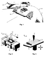
- Fig. 1 shows a schematic illustration of a fuselage 10 of an aircraft under repair.
- the fuselage 10 may comprise a shell or outer skin 1 which may be subject to damage, for example scratches, indentations, bucklings, fractures, cracks or other structural injuries.
- damage for example scratches, indentations, bucklings, fractures, cracks or other structural injuries.
- repair tools such as a repair robot arm 20 and/or a mobile crawler repair robot 30.
- both repair systems 20 and 30 may also perform milling and/or laser shock peening and/or conventional shock peening for pre-treating the damaged fuselage or fuselage component.
- Figs. 2 and 3 show schematic illustrations of different repair tool platforms which may be employed in the repair systems for the repair of damages in fuselages or fuselage components 10 such as the repair robot arm 20 or the mobile crawler repair robot 30 in Fig. 1.
- Fig. 2 shows a powder bed repair station 40 which comprises a laser 41, a deflection device 43, a powder bed container 44 and one or more powder feed cartridges 46, 47. A component to be repaired is placed in the powder bed of the powder bed container 44.
- the powder feed cartridges 46, 47 hold a basic metal powder substance comprising laser-fusible particles.
- the laser 41 for example an infra-red laser, emits a laser beam 42 which is directed by a deflective device 43 including 2D scanning optics onto the powder bed container 44.
- the laser beam 42 defines a two-dimensional pattern in the thin bed of metal powder.
- the metal powder is fused to form a solid layer.
- the powder bed container 44 is lowered in vertical direction by some elevation mechanism.
- the powder bed is then replenished to the original level using a powder feed roller 45 which is moved horizontally in order to convey new powder from the powder feed cartridges 46, 47 and deposit a uniform layer above the previously fused layer.
- the process of selectively fusing the next layer is then repeated.
- a three-dimensional structure is progressively built up being composed of multiple two-dimensional individual layers the thickness of which is typically on the order of several tens of ⁇ m.
- a wire feed repair station 50 comprises a wire guiding device 51 which builds up layers of wire 52 onto a build-up table 53. Depending on the length, orientation and segmentation of the wires 20, any desired three-dimensional structure made from a multitude of wire pieces may be progressively built up.
- the wires 52 are fused together using an electron beam source, a laser source or any other suitable source for selectively coupling melting of fusing heat into the wires 52.
- Fig. 4 schematically depicts stages of a repair procedure of a fuselage component 1 having a damaged area 2.
- the fuselage component 1 may particularly be a shell component of an aircraft or spacecraft.
- the damaged area 2 - as shown in stage (a) - may for example be a bulge, a dent, a scratch, an indentation, a buckling, a crack, a fracture or any similar structural damage of the fuselage component 1.
- the fuselage component 1 may for example comprise or consist of AlMgSc alloy such as Scalmalloy®.
- component material is removed from one surface around the damaged area 2 to form a recess 3 or gap in the fuselage component 1.
- the recess 3 may in particular reach through the entire thickness of the fuselage component 1 to the other surface.
- the removal of component material may comprise any suitable process such as milling, machining or cutting.
- the pre-treated machined or milled intermediate component is shown exemplarily in stage (b).
- a doubler 5 is attached to one surface of the fuselage component 1, the at least one doubler 5 covering the region around the damaged area 2.
- the doubler 5 may for example be a rectangular or circular doubler plate or doubler foil, as exemplarily shown in stage (c).
- the doubler 5 may for example be glued to the surface of the fuselage component 1.
- the doubler 5 may be riveted to the surface of the fuselage component 1.
- the recess 3 is filled with a filler material 6 using additive layer manufacturing, ALM.
- ALM is performed using powder bed technology or wire feed technology.
- a repair robot arm 20 or a crawler repair robot 30 as shown in Fig. 1 may be employed, using repair stations 40 or 50 as exemplarily illustrated in Figs. 2 and 3 , respectively, depending on the desired ALM technology.
- the filler material 6 is fabricated in such a way that a smooth surface opposite to the surface with the doubler 5 is created, as exemplarily shown in stage (d).
- the smooth surface may be an outside shell surface of the fuselage component 1.
- Fig. 5 schematically illustrates stages of a variant of an ALM procedure for repairing fuselage components 1 of an aircraft.
- the fuselage component 1 comprises a stringer or frame 7 in the region of the damaged area 2, as shown in stage (a).
- stage (b) After machining or milling the recess 3 as shown in stage (b), at least two doubler brackets 5a, 5b are attached to the surface of the fuselage component 1, the doubler brackets 5a, 5b being adjoined to the stringer or frame 7, as shown in stage (c).
- the form, type, number and shape of the doubler brackets 5a, 5b may vary depending on the joint geometry of the stringer or frame 7 with the fuselage component 1 at the particular damage region 2.
- the respective recess 3 is filled with filler material 6 using additive layer manufacturing, ALM.
- Fig. 6 schematically illustrates a method for repairing fuselage components of an aircraft.
- the method M may in particular be employed in repairing fuselage components 1 as shown in Figs. 4 and 5 .
- component material in a region around a damaged area 2 is removed to form a recess 3 in the fuselage component 1.
- At least one doubler is then attached to one surface of the fuselage component 1 at M2, the at least one doubler covering the region around the damaged area 2.
- the recess 3 is filled with a filler material 6 using additive layer manufacturing, ALM.
Abstract
Description
- The present invention relates to a repair method for fuselage components of aircraft or spacecraft, in particular by using additive layer manufacturing (ALM) and/or additive manufacturing (AM) processes.
- Metal fuselage components of aircraft or spacecraft need to be repaired, if the structural integrity of the component is comprised by ditches, scratches, indentations or bucklings. A typical repair process for metal and carbon fibre reinforced polymers (CFRP) structures involves removing the damaged structure and closing the resulting hole or gap by means of riveted or glued patches.
- Wiedemann, J.: "Leichtbau 2: Konstruktion"; 2nd ed., Springer Verlag, 1996, pp. 434-435, for example, discloses conventional repair methods for shell components of aircraft using bolted or adhesively bonded doublers which are adhered over a damaged area of the shell component similar to a patch or plaster.
- Additive layer manufacturing (ALM) techniques may be used in repairing damaged components, as exemplified in
EP 2 495 397 A2 - Of late, AlMgSc alloys are used as new aluminum alloys that have been developed for forming fuselage and shell components of aircraft. Those materials lower the production costs, fuel consumption and maintenance. Particularly joining processes may be a combination of welding and relaxation forming with AlMgSc alloys which have low density, high strength and toughness, good welding properties and high corrosion resistance.
- Repair methods for such fuselage components have hitherto been complex and pricy.
- One object of the invention is therefore to provide a repair method for fuselage components of aircraft which neither change the outer shape nor impair the structural behavior of the components.
- This object is achieved by a method for repairing fuselage components of an aircraft or spacecraft having the features of
claim 1. - A first aspect of the invention pertains to a method for repairing fuselage components of an aircraft or spacecraft, the method comprising removing component material in a region around a damaged area to form a recess in the fuselage component, attaching at least one doubler to one surface of the fuselage component, the at least one doubler covering the region around the damaged area, and filling the recess with a filler material using additive layer manufacturing.
- The idea on which the present invention is based is to use additive layer manufacturing (ALM) or additive manufacturing (AM) technology when repairing a damaged metal or CFRP fuselage component. With ALM/AM the structural properties of the repaired component is not compromised. It is possible to provide a one-to-one repair without changing the outer shape of the repaired component. Since the need for additional glue or rivets is obviated, the resulting repaired component is lighter than a conventionally repaired component. Finally, the introduction of internal stress into the repaired component is reduced since only low energy peaks are created when implementing the repair method of the invention.
- Advantageously, laser shock peening may be employed during the repair, thereby improving the fatigue resistance of the repaired component. Moreover, ALM/AM offers the opportunity to introduce crack stoppers into the filler of the removed damaged region in order to provide local reinforcements which prevent crack propagation.
- According to an embodiment of the method, ALM may be performed using powder bed technology. Alternatively, ALM may be performed using wire feed technology.
- According to a further embodiment of the method, the fuselage component may comprise an AlMgSc alloy. For example, Scalmalloy® may be used which is suited for high and very high-strength extrusions, offering exceptionally high fatigue properties and the same positive manufacturing propensities as AlMgSc sheet material. Scalmalloy® provides robust solutions for the use of aluminium alloys when high specific strength and exceptional high corrosion resistance are desired, while at the same time offering the additional advantages of robust manufacturing chains and low-cost production schemes. Additionally, it has the highest microstructure material stability for "low carbon footprint" applications.
- According to another embodiment of the method, removing component material may comprise milling, machining or cutting.
- According to another embodiment of the method, the recess in the fuselage component may reach through the fuselage component and comprise chamfered milling edges. Chamfered edges aid in implementing the process of ALM, especially in laser-assisted welding procedures.
- According to another embodiment of the method, the at least one doubler may be glued to the surface of the fuselage component. Preferably, the surface of the fuselage component may be the inner surface so that the outer surface of the shell component may be re-manufactured with a smooth surface.
- According to another embodiment of the method, the fuselage component may comprise a stringer or frame in the region of the damaged area, and attaching at least one doubler to one surface of the fuselage component may comprise attaching at least two doubler brackets on the surface of the fuselage component, the doubler brackets being adjoined to the stringer or frame. Particularly for damages in regions with complex joint geometries, the method of the first aspect is superior to conventional methods due to its flexibility in adapting to complex joints.
- The invention will be explained in greater detail with reference to exemplary embodiments depicted in the drawings as appended.
- The accompanying drawings are included to provide a further understanding of the present invention and are incorporated in and constitute a part of this specification. The drawings illustrate the embodiments of the present invention and together with the description serve to explain the principles of the invention. Other embodiments of the present invention and many of the intended advantages of the present invention will be readily appreciated as they become better understood by reference to the following detailed description. The elements of the drawings are not necessarily to scale relative to each other. Like reference numerals designate corresponding similar parts.
-
Fig. 1 schematically illustrates a fuselage of an aircraft under repair according to an embodiment of the invention. -
Fig. 2 schematically illustrates an additive layer manufacturing device. -
Fig. 3 schematically illustrates a further additive layer manufacturing device. -
Fig. 4 schematically illustrates stages of an additive layer manufacturing procedure for repairing fuselage components of an aircraft according to an embodiment of the invention. -
Fig. 5 schematically illustrates stages of an additive layer manufacturing procedure for repairing fuselage components of an aircraft according to another embodiment of the invention. -
Fig. 6 schematically illustrates a method for repairing fuselage components of an aircraft according to a further embodiment of the invention. - In the figures, like reference numerals denote like or functionally like components, unless indicated otherwise. Any directional terminology like "top", "bottom", "left", "right", "above", "below", "horizontal", "vertical", "back", "front", and similar terms are merely used for explanatory purposes and are not intended to delimit the embodiments to the specific arrangements as shown in the drawings.
- Although specific embodiments have been illustrated and described herein, it will be appreciated by those of ordinary skill in the art that a variety of alternate and/or equivalent implementations may be substituted for the specific embodiments shown and described without departing from the scope of the present invention. Generally, this application is intended to cover any adaptations or variations of the specific embodiments discussed herein.
- Free form fabrication (FFF), direct manufacturing (DM) and additive manufacturing (AM) belong to a general hierarchy of layer manufacturing (LM) methods. Those methods are used to form a three-dimensional solid object by sequentially building up layers of material. Any of such procedures will be referred to in the following description as additive layer manufacturing (ALM) without loss of generality. ALM techniques usually include selectively depositing material layer by layer, selectively fusing or solidifying the material and removing excess material, if needed.
-
Fig. 1 shows a schematic illustration of afuselage 10 of an aircraft under repair. Thefuselage 10 may comprise a shell orouter skin 1 which may be subject to damage, for example scratches, indentations, bucklings, fractures, cracks or other structural injuries. When repairing such damages it is possible to use different repair tools such as arepair robot arm 20 and/or a mobilecrawler repair robot 30. Apart from the actual repair, bothrepair systems -
Figs. 2 and 3 show schematic illustrations of different repair tool platforms which may be employed in the repair systems for the repair of damages in fuselages orfuselage components 10 such as therepair robot arm 20 or the mobilecrawler repair robot 30 inFig. 1. Fig. 2 shows a powderbed repair station 40 which comprises alaser 41, adeflection device 43, apowder bed container 44 and one or morepowder feed cartridges powder bed container 44. Thepowder feed cartridges - The
laser 41, for example an infra-red laser, emits alaser beam 42 which is directed by adeflective device 43 including 2D scanning optics onto thepowder bed container 44. Thelaser beam 42 defines a two-dimensional pattern in the thin bed of metal powder. At the impinging positions of thelaser beam 42, the metal powder is fused to form a solid layer. Upon completion of a layer, thepowder bed container 44 is lowered in vertical direction by some elevation mechanism. The powder bed is then replenished to the original level using apowder feed roller 45 which is moved horizontally in order to convey new powder from thepowder feed cartridges - Another possible ALM procedure is the wire feed technology as schematically depicted in
Fig. 3 . A wirefeed repair station 50 comprises awire guiding device 51 which builds up layers ofwire 52 onto a build-up table 53. Depending on the length, orientation and segmentation of thewires 20, any desired three-dimensional structure made from a multitude of wire pieces may be progressively built up. Thewires 52 are fused together using an electron beam source, a laser source or any other suitable source for selectively coupling melting of fusing heat into thewires 52. -
Fig. 4 schematically depicts stages of a repair procedure of afuselage component 1 having a damagedarea 2. Thefuselage component 1 may particularly be a shell component of an aircraft or spacecraft. The damaged area 2 - as shown in stage (a) - may for example be a bulge, a dent, a scratch, an indentation, a buckling, a crack, a fracture or any similar structural damage of thefuselage component 1. Thefuselage component 1 may for example comprise or consist of AlMgSc alloy such as Scalmalloy®. - First, component material is removed from one surface around the damaged
area 2 to form arecess 3 or gap in thefuselage component 1. Therecess 3 may in particular reach through the entire thickness of thefuselage component 1 to the other surface. The removal of component material may comprise any suitable process such as milling, machining or cutting. In particular, it may be advantageous to form therecess 3 in thefuselage component 1 in such a way that chamfered millingedges 4 are generated, resulting in a cone-shaped recess gap. The pre-treated machined or milled intermediate component is shown exemplarily in stage (b). - After forming the
recess 3, adoubler 5 is attached to one surface of thefuselage component 1, the at least onedoubler 5 covering the region around the damagedarea 2. Thedoubler 5 may for example be a rectangular or circular doubler plate or doubler foil, as exemplarily shown in stage (c). Thedoubler 5 may for example be glued to the surface of thefuselage component 1. Alternatively, thedoubler 5 may be riveted to the surface of thefuselage component 1. - Finally, the
recess 3 is filled with afiller material 6 using additive layer manufacturing, ALM. For example, ALM is performed using powder bed technology or wire feed technology. To this end, arepair robot arm 20 or acrawler repair robot 30 as shown inFig. 1 may be employed, usingrepair stations Figs. 2 and 3 , respectively, depending on the desired ALM technology. Thefiller material 6 is fabricated in such a way that a smooth surface opposite to the surface with thedoubler 5 is created, as exemplarily shown in stage (d). Advantageously, the smooth surface may be an outside shell surface of thefuselage component 1. -
Fig. 5 schematically illustrates stages of a variant of an ALM procedure for repairingfuselage components 1 of an aircraft. Unlike inFig. 4 thefuselage component 1 comprises a stringer or frame 7 in the region of the damagedarea 2, as shown in stage (a). After machining or milling therecess 3 as shown in stage (b), at least twodoubler brackets fuselage component 1, thedoubler brackets doubler brackets fuselage component 1 at theparticular damage region 2. - Again, as shown in stage (d), the
respective recess 3 is filled withfiller material 6 using additive layer manufacturing, ALM. -
Fig. 6 schematically illustrates a method for repairing fuselage components of an aircraft. The method M may in particular be employed in repairingfuselage components 1 as shown inFigs. 4 and 5 . - At M1, component material in a region around a damaged
area 2 is removed to form arecess 3 in thefuselage component 1. At least one doubler is then attached to one surface of thefuselage component 1 at M2, the at least one doubler covering the region around the damagedarea 2. Finally, at M3, therecess 3 is filled with afiller material 6 using additive layer manufacturing, ALM. - The methods and procedures as exemplarily discussed herein in conjunction with repair of damaged structural components may also be employed to join structural components or fuselage elements.
- In the foregoing detailed description, various features are grouped together in one or more examples or examples with the purpose of streamlining the disclosure. It is to be understood that the above description is intended to be illustrative, and not restrictive. It is intended to cover all alternatives, modifications and equivalents. Many other examples will be apparent to one skilled in the art upon reviewing the above specification. In particular, the embodiments and configurations described for the composite reinforcement components and structural elements can be applied accordingly to the aircraft or spacecraft according to the invention and the method according to the invention, and vice versa.
- The embodiments were chosen and described in order to best explain the principles of the invention and its practical applications, to thereby enable others skilled in the art to best utilize the invention and various embodiments with various modifications as are suited to the particular use contemplated. In the appended claims and throughout the specification, the terms "including" and "in which" are used as the plain-English equivalents of the respective terms "comprising" and "wherein," respectively. Furthermore, "a" or "one" does not exclude a plurality in the present case.
-
- 1
- Fuselage component
- 2
- Damaged area
- 3
- Recess
- 4
- Chamfer
- 5
- Doubler
- 5a
- Doubler bracket
- 5b
- Doubler bracket
- 6
- Filler
- 7
- Stringer/Frame
- 10
- Fuselage
- 20
- Repair robot arm
- 30
- Mobile repair robot
- 40
- Powder bed repair station
- 41
- Laser
- 42
- Laser beam
- 43
- Deflection device
- 44
- Powder bed container
- 45
- Powder feed roller
- 46
- Powder feed cartridge
- 47
- Powder feed cartridge
- 50
- Wire feed repair station
- 51
- Wire guiding device
- 52
- Wire
- 53
- Build-up table
- M
- Method
- M1
- Method step
- M2
- Method step
- M3
- Method step
- M4
- Method step
- M5
- Method step
Claims (8)
- Method (M) for repairing a fuselage component (1) of an aircraft or spacecraft, the method (M) comprising:removing (M1) component material in a region around a damaged area (2) to form a recess (3) in the fuselage component (1);attaching (M2) at least one doubler (5; 5a, 5b) to one surface of the fuselage component (1), the at least one doubler (5; 5a, 5b) covering the region around the damaged area (2); andfilling (M3) the recess (3) with a filler material (6) using additive layer manufacturing, ALM.
- Method (M) according to claim 1, wherein ALM is performed using powder bed technology.
- Method (M) according to claim 1, wherein ALM is performed using wire feed technology.
- Method (M) according to one of the claims 1 to 3, wherein the fuselage component (1) comprises an AlMgSc alloy.
- Method (M) according to one of the claims 1 to 3, wherein removing (M1) component material comprises milling, machining or cutting.
- Method (M) according to claim 5, wherein the recess (3) in the fuselage component (1) reaches through the fuselage component (1) and comprises chamfered milling edges (4).
- Method (M) according to one of the claims 1 to 6, wherein the at least one doubler (5; 5a, 5b) is glued to the surface of the fuselage component (1).
- Method (M) according to one of the claims 1 to 7, wherein the fuselage component (1) comprises a stringer or frame (7) in the region of the damaged area (2), and wherein attaching (M2) at least one doubler (5; 5a, 5b) to one surface of the fuselage component (1) comprises attaching at least two doubler brackets (5a, 5b) to the surface of the fuselage component (1), the doubler brackets (5a, 5b) being adjoined to the stringer or frame (7).
Priority Applications (1)
| Application Number | Priority Date | Filing Date | Title |
|---|---|---|---|
| EP13192836.8A EP2873620B1 (en) | 2013-11-14 | 2013-11-14 | Repair method for fuselage components of aircraft or spacecraft |
Applications Claiming Priority (1)
| Application Number | Priority Date | Filing Date | Title |
|---|---|---|---|
| EP13192836.8A EP2873620B1 (en) | 2013-11-14 | 2013-11-14 | Repair method for fuselage components of aircraft or spacecraft |
Publications (2)
| Publication Number | Publication Date |
|---|---|
| EP2873620A1 true EP2873620A1 (en) | 2015-05-20 |
| EP2873620B1 EP2873620B1 (en) | 2018-05-16 |
Family
ID=49584625
Family Applications (1)
| Application Number | Title | Priority Date | Filing Date |
|---|---|---|---|
| EP13192836.8A Active EP2873620B1 (en) | 2013-11-14 | 2013-11-14 | Repair method for fuselage components of aircraft or spacecraft |
Country Status (1)
| Country | Link |
|---|---|
| EP (1) | EP2873620B1 (en) |
Cited By (9)
| Publication number | Priority date | Publication date | Assignee | Title |
|---|---|---|---|---|
| EP3120968A1 (en) * | 2015-07-20 | 2017-01-25 | Goodrich Corporation | Methods for repair of aircraft wheel and brake parts |
| WO2017170024A1 (en) * | 2016-03-31 | 2017-10-05 | コニカミノルタ株式会社 | Three-dimensionally shaped product production method and production device |
| EP3293105A1 (en) * | 2016-09-07 | 2018-03-14 | The Boeing Company | Method of repairing damage to fuselage barrel and associated apparatus and system |
| US10329033B2 (en) * | 2015-01-16 | 2019-06-25 | Sikorsky Aircraft Corporation | Cold spray method to join or in certain cases strengthen metals |
| EP3546125A1 (en) * | 2018-03-27 | 2019-10-02 | Airbus Defence and Space GmbH | Aluminium and/or magnesium alloy containing blasting material for blast cleaning of body containing al and/or mg |
| US10442002B2 (en) | 2014-11-19 | 2019-10-15 | Airbus Operations Gmbh | Manufacturing of components of a vehicle using additive layer manufacturing |
| US10507553B2 (en) | 2016-11-11 | 2019-12-17 | Airbus Operations Gmbh | Method for reconditioning of a damaged portion of a component and insert therefor |
| CN110976869A (en) * | 2019-12-25 | 2020-04-10 | 长安大学 | Part additive composite manufacturing device and method |
| CN113665783A (en) * | 2021-10-09 | 2021-11-19 | 中国商用飞机有限责任公司 | Repair for aircraft stringers |
Citations (7)
| Publication number | Priority date | Publication date | Assignee | Title |
|---|---|---|---|---|
| WO2001020534A1 (en) * | 1999-09-16 | 2001-03-22 | Solidica, Inc. | Object consolidation through sequential material deposition |
| US20090282664A1 (en) * | 2008-04-30 | 2009-11-19 | Deutsches Zentrum Fur Luftund Raumfahrt E.V. | Method for repairing a flight component and patch therefor |
| US20110107578A1 (en) * | 2008-02-29 | 2011-05-12 | Joern Paul | Method for tolerance compensation between two fibre composite components |
| EP2495397A2 (en) | 2011-03-04 | 2012-09-05 | Honeywell International Inc. | Methods for repairing turbine components |
| WO2012131327A1 (en) * | 2011-03-25 | 2012-10-04 | Bae Systems Plc | Additive layer manufacturing |
| CA2833925A1 (en) * | 2011-04-26 | 2012-11-01 | Airbus Operations Gmbh | Force introduction fitting for lightweight components |
| US20130270750A1 (en) * | 2012-03-29 | 2013-10-17 | Gordon R. Green | Apparatus and methods for additive-layer manufacturing of an article |
-
2013
- 2013-11-14 EP EP13192836.8A patent/EP2873620B1/en active Active
Patent Citations (7)
| Publication number | Priority date | Publication date | Assignee | Title |
|---|---|---|---|---|
| WO2001020534A1 (en) * | 1999-09-16 | 2001-03-22 | Solidica, Inc. | Object consolidation through sequential material deposition |
| US20110107578A1 (en) * | 2008-02-29 | 2011-05-12 | Joern Paul | Method for tolerance compensation between two fibre composite components |
| US20090282664A1 (en) * | 2008-04-30 | 2009-11-19 | Deutsches Zentrum Fur Luftund Raumfahrt E.V. | Method for repairing a flight component and patch therefor |
| EP2495397A2 (en) | 2011-03-04 | 2012-09-05 | Honeywell International Inc. | Methods for repairing turbine components |
| WO2012131327A1 (en) * | 2011-03-25 | 2012-10-04 | Bae Systems Plc | Additive layer manufacturing |
| CA2833925A1 (en) * | 2011-04-26 | 2012-11-01 | Airbus Operations Gmbh | Force introduction fitting for lightweight components |
| US20130270750A1 (en) * | 2012-03-29 | 2013-10-17 | Gordon R. Green | Apparatus and methods for additive-layer manufacturing of an article |
Non-Patent Citations (1)
| Title |
|---|
| WIEDEMANN, J.: "Leichtbau 2: Konstruktion", 1996, SPRINGER VERLAG, pages: 434 - 435 |
Cited By (12)
| Publication number | Priority date | Publication date | Assignee | Title |
|---|---|---|---|---|
| US10442002B2 (en) | 2014-11-19 | 2019-10-15 | Airbus Operations Gmbh | Manufacturing of components of a vehicle using additive layer manufacturing |
| US10329033B2 (en) * | 2015-01-16 | 2019-06-25 | Sikorsky Aircraft Corporation | Cold spray method to join or in certain cases strengthen metals |
| EP3120968A1 (en) * | 2015-07-20 | 2017-01-25 | Goodrich Corporation | Methods for repair of aircraft wheel and brake parts |
| EP3120968B1 (en) | 2015-07-20 | 2018-11-21 | Goodrich Corporation | Methods for repair of aircraft wheel and brake parts |
| WO2017170024A1 (en) * | 2016-03-31 | 2017-10-05 | コニカミノルタ株式会社 | Three-dimensionally shaped product production method and production device |
| EP3293105A1 (en) * | 2016-09-07 | 2018-03-14 | The Boeing Company | Method of repairing damage to fuselage barrel and associated apparatus and system |
| US10308342B2 (en) | 2016-09-07 | 2019-06-04 | The Boeing Company | Method of repairing damage to fuselage barrel and associated apparatus and system |
| US11104412B2 (en) | 2016-09-07 | 2021-08-31 | The Boeing Company | Method of repairing damage to fuselage barrel and associated apparatus and system |
| US10507553B2 (en) | 2016-11-11 | 2019-12-17 | Airbus Operations Gmbh | Method for reconditioning of a damaged portion of a component and insert therefor |
| EP3546125A1 (en) * | 2018-03-27 | 2019-10-02 | Airbus Defence and Space GmbH | Aluminium and/or magnesium alloy containing blasting material for blast cleaning of body containing al and/or mg |
| CN110976869A (en) * | 2019-12-25 | 2020-04-10 | 长安大学 | Part additive composite manufacturing device and method |
| CN113665783A (en) * | 2021-10-09 | 2021-11-19 | 中国商用飞机有限责任公司 | Repair for aircraft stringers |
Also Published As
| Publication number | Publication date |
|---|---|
| EP2873620B1 (en) | 2018-05-16 |
Similar Documents
| Publication | Publication Date | Title |
|---|---|---|
| EP2873620B1 (en) | Repair method for fuselage components of aircraft or spacecraft | |
| US20150141234A1 (en) | Manufacturing method and manufacturing tool for reinforced structural elements | |
| US9751610B2 (en) | Passenger door corner component and manufacturing method for passenger door corner component of aircraft or spacecraft | |
| Rajan et al. | Trends in aluminium alloy development and their joining methods | |
| US8316687B2 (en) | Method for making a tool used to manufacture composite parts | |
| JP5838091B2 (en) | Structural part machining method | |
| US8110054B2 (en) | Method for connection at least two pieces of sheet material, particularly at least two metal sheets for a lightweight structure as well a joining and lightweight structure | |
| EP2974814A1 (en) | Lattice reinforced radius filler | |
| CN110802302A (en) | Arc fuse wire additive manufacturing method of multidirectional steel node | |
| EP3216691A1 (en) | Airframe component and methods for manufacturing an airframe component | |
| JP2019059226A (en) | Integral nut holding cradle for nut plate assembly, and manufacturing method using additive manufacture | |
| CN109941358B (en) | Method for applying a reinforcement of a metallic material to a member of a metallic material | |
| CN104551422B (en) | The welding procedure of large-scale magnesium alloy expanding table top | |
| WO2017027144A1 (en) | Multi-sectional composite tooling | |
| Buffa et al. | A new friction stir welding based technique for corner fillet joints: experimental and numerical study | |
| US8973241B1 (en) | Method and apparatus for joining composite structures | |
| CN113183466B (en) | Hybrid component including additive manufacturing | |
| CN109551081A (en) | A kind of electric arc increasing material manufacturing restorative procedure using the hardened structure of assistant formation | |
| JP2016098817A (en) | Modified bucket platforms of turbine buckets and methods for modifying bucket platforms of turbine buckets | |
| RU2730332C2 (en) | Preparation of edges for laser welding | |
| Falken et al. | From development of multi-material skins to morphing flight hardware production | |
| Scheck et al. | Technical overview of additive manufacturing | |
| Tera et al. | Study of incremental deep-drawing of bimetallic sheets | |
| KR102210115B1 (en) | An unit-cell structure and A sandwich plate comprising the same | |
| EP3957419A1 (en) | Lightweight stiffened panels made using additive manufacturing techniques |
Legal Events
| Date | Code | Title | Description |
|---|---|---|---|
| PUAI | Public reference made under article 153(3) epc to a published international application that has entered the european phase |
Free format text: ORIGINAL CODE: 0009012 |
|
| 17P | Request for examination filed |
Effective date: 20131114 |
|
| AK | Designated contracting states |
Kind code of ref document: A1 Designated state(s): AL AT BE BG CH CY CZ DE DK EE ES FI FR GB GR HR HU IE IS IT LI LT LU LV MC MK MT NL NO PL PT RO RS SE SI SK SM TR |
|
| AX | Request for extension of the european patent |
Extension state: BA ME |
|
| R17P | Request for examination filed (corrected) |
Effective date: 20151110 |
|
| RBV | Designated contracting states (corrected) |
Designated state(s): AL AT BE BG CH CY CZ DE DK EE ES FI FR GB GR HR HU IE IS IT LI LT LU LV MC MK MT NL NO PL PT RO RS SE SI SK SM TR |
|
| GRAP | Despatch of communication of intention to grant a patent |
Free format text: ORIGINAL CODE: EPIDOSNIGR1 |
|
| STAA | Information on the status of an ep patent application or granted ep patent |
Free format text: STATUS: GRANT OF PATENT IS INTENDED |
|
| INTG | Intention to grant announced |
Effective date: 20171215 |
|
| GRAS | Grant fee paid |
Free format text: ORIGINAL CODE: EPIDOSNIGR3 |
|
| GRAA | (expected) grant |
Free format text: ORIGINAL CODE: 0009210 |
|
| STAA | Information on the status of an ep patent application or granted ep patent |
Free format text: STATUS: THE PATENT HAS BEEN GRANTED |
|
| AK | Designated contracting states |
Kind code of ref document: B1 Designated state(s): AL AT BE BG CH CY CZ DE DK EE ES FI FR GB GR HR HU IE IS IT LI LT LU LV MC MK MT NL NO PL PT RO RS SE SI SK SM TR |
|
| REG | Reference to a national code |
Ref country code: GB Ref legal event code: FG4D |
|
| REG | Reference to a national code |
Ref country code: CH Ref legal event code: EP |
|
| REG | Reference to a national code |
Ref country code: IE Ref legal event code: FG4D |
|
| REG | Reference to a national code |
Ref country code: DE Ref legal event code: R096 Ref document number: 602013037463 Country of ref document: DE |
|
| REG | Reference to a national code |
Ref country code: AT Ref legal event code: REF Ref document number: 999315 Country of ref document: AT Kind code of ref document: T Effective date: 20180615 |
|
| REG | Reference to a national code |
Ref country code: NL Ref legal event code: MP Effective date: 20180516 |
|
| REG | Reference to a national code |
Ref country code: LT Ref legal event code: MG4D |
|
| PG25 | Lapsed in a contracting state [announced via postgrant information from national office to epo] |
Ref country code: NO Free format text: LAPSE BECAUSE OF FAILURE TO SUBMIT A TRANSLATION OF THE DESCRIPTION OR TO PAY THE FEE WITHIN THE PRESCRIBED TIME-LIMIT Effective date: 20180816 Ref country code: FI Free format text: LAPSE BECAUSE OF FAILURE TO SUBMIT A TRANSLATION OF THE DESCRIPTION OR TO PAY THE FEE WITHIN THE PRESCRIBED TIME-LIMIT Effective date: 20180516 Ref country code: LT Free format text: LAPSE BECAUSE OF FAILURE TO SUBMIT A TRANSLATION OF THE DESCRIPTION OR TO PAY THE FEE WITHIN THE PRESCRIBED TIME-LIMIT Effective date: 20180516 Ref country code: BG Free format text: LAPSE BECAUSE OF FAILURE TO SUBMIT A TRANSLATION OF THE DESCRIPTION OR TO PAY THE FEE WITHIN THE PRESCRIBED TIME-LIMIT Effective date: 20180816 Ref country code: ES Free format text: LAPSE BECAUSE OF FAILURE TO SUBMIT A TRANSLATION OF THE DESCRIPTION OR TO PAY THE FEE WITHIN THE PRESCRIBED TIME-LIMIT Effective date: 20180516 Ref country code: SE Free format text: LAPSE BECAUSE OF FAILURE TO SUBMIT A TRANSLATION OF THE DESCRIPTION OR TO PAY THE FEE WITHIN THE PRESCRIBED TIME-LIMIT Effective date: 20180516 |
|
| PG25 | Lapsed in a contracting state [announced via postgrant information from national office to epo] |
Ref country code: RS Free format text: LAPSE BECAUSE OF FAILURE TO SUBMIT A TRANSLATION OF THE DESCRIPTION OR TO PAY THE FEE WITHIN THE PRESCRIBED TIME-LIMIT Effective date: 20180516 Ref country code: HR Free format text: LAPSE BECAUSE OF FAILURE TO SUBMIT A TRANSLATION OF THE DESCRIPTION OR TO PAY THE FEE WITHIN THE PRESCRIBED TIME-LIMIT Effective date: 20180516 Ref country code: LV Free format text: LAPSE BECAUSE OF FAILURE TO SUBMIT A TRANSLATION OF THE DESCRIPTION OR TO PAY THE FEE WITHIN THE PRESCRIBED TIME-LIMIT Effective date: 20180516 Ref country code: GR Free format text: LAPSE BECAUSE OF FAILURE TO SUBMIT A TRANSLATION OF THE DESCRIPTION OR TO PAY THE FEE WITHIN THE PRESCRIBED TIME-LIMIT Effective date: 20180817 Ref country code: NL Free format text: LAPSE BECAUSE OF FAILURE TO SUBMIT A TRANSLATION OF THE DESCRIPTION OR TO PAY THE FEE WITHIN THE PRESCRIBED TIME-LIMIT Effective date: 20180516 |
|
| REG | Reference to a national code |
Ref country code: AT Ref legal event code: MK05 Ref document number: 999315 Country of ref document: AT Kind code of ref document: T Effective date: 20180516 |
|
| PG25 | Lapsed in a contracting state [announced via postgrant information from national office to epo] |
Ref country code: DK Free format text: LAPSE BECAUSE OF FAILURE TO SUBMIT A TRANSLATION OF THE DESCRIPTION OR TO PAY THE FEE WITHIN THE PRESCRIBED TIME-LIMIT Effective date: 20180516 Ref country code: PL Free format text: LAPSE BECAUSE OF FAILURE TO SUBMIT A TRANSLATION OF THE DESCRIPTION OR TO PAY THE FEE WITHIN THE PRESCRIBED TIME-LIMIT Effective date: 20180516 Ref country code: CZ Free format text: LAPSE BECAUSE OF FAILURE TO SUBMIT A TRANSLATION OF THE DESCRIPTION OR TO PAY THE FEE WITHIN THE PRESCRIBED TIME-LIMIT Effective date: 20180516 Ref country code: SK Free format text: LAPSE BECAUSE OF FAILURE TO SUBMIT A TRANSLATION OF THE DESCRIPTION OR TO PAY THE FEE WITHIN THE PRESCRIBED TIME-LIMIT Effective date: 20180516 Ref country code: RO Free format text: LAPSE BECAUSE OF FAILURE TO SUBMIT A TRANSLATION OF THE DESCRIPTION OR TO PAY THE FEE WITHIN THE PRESCRIBED TIME-LIMIT Effective date: 20180516 Ref country code: EE Free format text: LAPSE BECAUSE OF FAILURE TO SUBMIT A TRANSLATION OF THE DESCRIPTION OR TO PAY THE FEE WITHIN THE PRESCRIBED TIME-LIMIT Effective date: 20180516 Ref country code: AT Free format text: LAPSE BECAUSE OF FAILURE TO SUBMIT A TRANSLATION OF THE DESCRIPTION OR TO PAY THE FEE WITHIN THE PRESCRIBED TIME-LIMIT Effective date: 20180516 |
|
| REG | Reference to a national code |
Ref country code: DE Ref legal event code: R097 Ref document number: 602013037463 Country of ref document: DE |
|
| PG25 | Lapsed in a contracting state [announced via postgrant information from national office to epo] |
Ref country code: IT Free format text: LAPSE BECAUSE OF FAILURE TO SUBMIT A TRANSLATION OF THE DESCRIPTION OR TO PAY THE FEE WITHIN THE PRESCRIBED TIME-LIMIT Effective date: 20180516 Ref country code: SM Free format text: LAPSE BECAUSE OF FAILURE TO SUBMIT A TRANSLATION OF THE DESCRIPTION OR TO PAY THE FEE WITHIN THE PRESCRIBED TIME-LIMIT Effective date: 20180516 |
|
| PLBE | No opposition filed within time limit |
Free format text: ORIGINAL CODE: 0009261 |
|
| STAA | Information on the status of an ep patent application or granted ep patent |
Free format text: STATUS: NO OPPOSITION FILED WITHIN TIME LIMIT |
|
| 26N | No opposition filed |
Effective date: 20190219 |
|
| PG25 | Lapsed in a contracting state [announced via postgrant information from national office to epo] |
Ref country code: SI Free format text: LAPSE BECAUSE OF FAILURE TO SUBMIT A TRANSLATION OF THE DESCRIPTION OR TO PAY THE FEE WITHIN THE PRESCRIBED TIME-LIMIT Effective date: 20180516 |
|
| REG | Reference to a national code |
Ref country code: CH Ref legal event code: PL |
|
| PG25 | Lapsed in a contracting state [announced via postgrant information from national office to epo] |
Ref country code: MC Free format text: LAPSE BECAUSE OF FAILURE TO SUBMIT A TRANSLATION OF THE DESCRIPTION OR TO PAY THE FEE WITHIN THE PRESCRIBED TIME-LIMIT Effective date: 20180516 Ref country code: LU Free format text: LAPSE BECAUSE OF NON-PAYMENT OF DUE FEES Effective date: 20181114 |
|
| REG | Reference to a national code |
Ref country code: BE Ref legal event code: MM Effective date: 20181130 |
|
| REG | Reference to a national code |
Ref country code: IE Ref legal event code: MM4A |
|
| PG25 | Lapsed in a contracting state [announced via postgrant information from national office to epo] |
Ref country code: LI Free format text: LAPSE BECAUSE OF NON-PAYMENT OF DUE FEES Effective date: 20181130 Ref country code: CH Free format text: LAPSE BECAUSE OF NON-PAYMENT OF DUE FEES Effective date: 20181130 |
|
| PG25 | Lapsed in a contracting state [announced via postgrant information from national office to epo] |
Ref country code: IE Free format text: LAPSE BECAUSE OF NON-PAYMENT OF DUE FEES Effective date: 20181114 |
|
| PG25 | Lapsed in a contracting state [announced via postgrant information from national office to epo] |
Ref country code: BE Free format text: LAPSE BECAUSE OF NON-PAYMENT OF DUE FEES Effective date: 20181130 Ref country code: AL Free format text: LAPSE BECAUSE OF FAILURE TO SUBMIT A TRANSLATION OF THE DESCRIPTION OR TO PAY THE FEE WITHIN THE PRESCRIBED TIME-LIMIT Effective date: 20180516 |
|
| PG25 | Lapsed in a contracting state [announced via postgrant information from national office to epo] |
Ref country code: MT Free format text: LAPSE BECAUSE OF NON-PAYMENT OF DUE FEES Effective date: 20181114 |
|
| PG25 | Lapsed in a contracting state [announced via postgrant information from national office to epo] |
Ref country code: TR Free format text: LAPSE BECAUSE OF FAILURE TO SUBMIT A TRANSLATION OF THE DESCRIPTION OR TO PAY THE FEE WITHIN THE PRESCRIBED TIME-LIMIT Effective date: 20180516 |
|
| PG25 | Lapsed in a contracting state [announced via postgrant information from national office to epo] |
Ref country code: PT Free format text: LAPSE BECAUSE OF FAILURE TO SUBMIT A TRANSLATION OF THE DESCRIPTION OR TO PAY THE FEE WITHIN THE PRESCRIBED TIME-LIMIT Effective date: 20180516 |
|
| PG25 | Lapsed in a contracting state [announced via postgrant information from national office to epo] |
Ref country code: HU Free format text: LAPSE BECAUSE OF FAILURE TO SUBMIT A TRANSLATION OF THE DESCRIPTION OR TO PAY THE FEE WITHIN THE PRESCRIBED TIME-LIMIT; INVALID AB INITIO Effective date: 20131114 Ref country code: CY Free format text: LAPSE BECAUSE OF FAILURE TO SUBMIT A TRANSLATION OF THE DESCRIPTION OR TO PAY THE FEE WITHIN THE PRESCRIBED TIME-LIMIT Effective date: 20180516 Ref country code: MK Free format text: LAPSE BECAUSE OF NON-PAYMENT OF DUE FEES Effective date: 20180516 |
|
| PG25 | Lapsed in a contracting state [announced via postgrant information from national office to epo] |
Ref country code: IS Free format text: LAPSE BECAUSE OF FAILURE TO SUBMIT A TRANSLATION OF THE DESCRIPTION OR TO PAY THE FEE WITHIN THE PRESCRIBED TIME-LIMIT Effective date: 20180916 |
|
| PGFP | Annual fee paid to national office [announced via postgrant information from national office to epo] |
Ref country code: GB Payment date: 20231123 Year of fee payment: 11 |
|
| PGFP | Annual fee paid to national office [announced via postgrant information from national office to epo] |
Ref country code: FR Payment date: 20231120 Year of fee payment: 11 Ref country code: DE Payment date: 20231121 Year of fee payment: 11 |