EP4512598A1 - Molding die, resin molding apparatus, and resin molding system - Google Patents
Molding die, resin molding apparatus, and resin molding system Download PDFInfo
- Publication number
- EP4512598A1 EP4512598A1 EP23815476.9A EP23815476A EP4512598A1 EP 4512598 A1 EP4512598 A1 EP 4512598A1 EP 23815476 A EP23815476 A EP 23815476A EP 4512598 A1 EP4512598 A1 EP 4512598A1
- Authority
- EP
- European Patent Office
- Prior art keywords
- mold
- slit
- terminal
- resin
- resin molding
- Prior art date
- Legal status (The legal status is an assumption and is not a legal conclusion. Google has not performed a legal analysis and makes no representation as to the accuracy of the status listed.)
- Pending
Links
Images





Classifications
-
- B—PERFORMING OPERATIONS; TRANSPORTING
- B29—WORKING OF PLASTICS; WORKING OF SUBSTANCES IN A PLASTIC STATE IN GENERAL
- B29C—SHAPING OR JOINING OF PLASTICS; SHAPING OF MATERIAL IN A PLASTIC STATE, NOT OTHERWISE PROVIDED FOR; AFTER-TREATMENT OF THE SHAPED PRODUCTS, e.g. REPAIRING
- B29C45/00—Injection moulding, i.e. forcing the required volume of moulding material through a nozzle into a closed mould; Apparatus therefor
- B29C45/14—Injection moulding, i.e. forcing the required volume of moulding material through a nozzle into a closed mould; Apparatus therefor incorporating preformed parts or layers, e.g. injection moulding around inserts or for coating articles
-
- B—PERFORMING OPERATIONS; TRANSPORTING
- B29—WORKING OF PLASTICS; WORKING OF SUBSTANCES IN A PLASTIC STATE IN GENERAL
- B29C—SHAPING OR JOINING OF PLASTICS; SHAPING OF MATERIAL IN A PLASTIC STATE, NOT OTHERWISE PROVIDED FOR; AFTER-TREATMENT OF THE SHAPED PRODUCTS, e.g. REPAIRING
- B29C33/00—Moulds or cores; Details thereof or accessories therefor
- B29C33/12—Moulds or cores; Details thereof or accessories therefor with incorporated means for positioning inserts, e.g. labels
-
- B—PERFORMING OPERATIONS; TRANSPORTING
- B29—WORKING OF PLASTICS; WORKING OF SUBSTANCES IN A PLASTIC STATE IN GENERAL
- B29C—SHAPING OR JOINING OF PLASTICS; SHAPING OF MATERIAL IN A PLASTIC STATE, NOT OTHERWISE PROVIDED FOR; AFTER-TREATMENT OF THE SHAPED PRODUCTS, e.g. REPAIRING
- B29C33/00—Moulds or cores; Details thereof or accessories therefor
- B29C33/0038—Moulds or cores; Details thereof or accessories therefor with sealing means or the like
- B29C33/0044—Moulds or cores; Details thereof or accessories therefor with sealing means or the like for sealing off parts of inserts projecting into the mould cavity
-
- B—PERFORMING OPERATIONS; TRANSPORTING
- B29—WORKING OF PLASTICS; WORKING OF SUBSTANCES IN A PLASTIC STATE IN GENERAL
- B29C—SHAPING OR JOINING OF PLASTICS; SHAPING OF MATERIAL IN A PLASTIC STATE, NOT OTHERWISE PROVIDED FOR; AFTER-TREATMENT OF THE SHAPED PRODUCTS, e.g. REPAIRING
- B29C45/00—Injection moulding, i.e. forcing the required volume of moulding material through a nozzle into a closed mould; Apparatus therefor
- B29C45/0025—Preventing defects on the moulded article, e.g. weld lines, shrinkage marks
-
- B—PERFORMING OPERATIONS; TRANSPORTING
- B29—WORKING OF PLASTICS; WORKING OF SUBSTANCES IN A PLASTIC STATE IN GENERAL
- B29C—SHAPING OR JOINING OF PLASTICS; SHAPING OF MATERIAL IN A PLASTIC STATE, NOT OTHERWISE PROVIDED FOR; AFTER-TREATMENT OF THE SHAPED PRODUCTS, e.g. REPAIRING
- B29C45/00—Injection moulding, i.e. forcing the required volume of moulding material through a nozzle into a closed mould; Apparatus therefor
- B29C45/02—Transfer moulding, i.e. transferring the required volume of moulding material by a plunger from a "shot" cavity into a mould cavity
-
- B—PERFORMING OPERATIONS; TRANSPORTING
- B29—WORKING OF PLASTICS; WORKING OF SUBSTANCES IN A PLASTIC STATE IN GENERAL
- B29C—SHAPING OR JOINING OF PLASTICS; SHAPING OF MATERIAL IN A PLASTIC STATE, NOT OTHERWISE PROVIDED FOR; AFTER-TREATMENT OF THE SHAPED PRODUCTS, e.g. REPAIRING
- B29C45/00—Injection moulding, i.e. forcing the required volume of moulding material through a nozzle into a closed mould; Apparatus therefor
- B29C45/14—Injection moulding, i.e. forcing the required volume of moulding material through a nozzle into a closed mould; Apparatus therefor incorporating preformed parts or layers, e.g. injection moulding around inserts or for coating articles
- B29C45/14008—Inserting articles into the mould
-
- B—PERFORMING OPERATIONS; TRANSPORTING
- B29—WORKING OF PLASTICS; WORKING OF SUBSTANCES IN A PLASTIC STATE IN GENERAL
- B29C—SHAPING OR JOINING OF PLASTICS; SHAPING OF MATERIAL IN A PLASTIC STATE, NOT OTHERWISE PROVIDED FOR; AFTER-TREATMENT OF THE SHAPED PRODUCTS, e.g. REPAIRING
- B29C45/00—Injection moulding, i.e. forcing the required volume of moulding material through a nozzle into a closed mould; Apparatus therefor
- B29C45/14—Injection moulding, i.e. forcing the required volume of moulding material through a nozzle into a closed mould; Apparatus therefor incorporating preformed parts or layers, e.g. injection moulding around inserts or for coating articles
- B29C45/14336—Coating a portion of the article, e.g. the edge of the article
- B29C45/14418—Sealing means between mould and article
-
- B—PERFORMING OPERATIONS; TRANSPORTING
- B29—WORKING OF PLASTICS; WORKING OF SUBSTANCES IN A PLASTIC STATE IN GENERAL
- B29C—SHAPING OR JOINING OF PLASTICS; SHAPING OF MATERIAL IN A PLASTIC STATE, NOT OTHERWISE PROVIDED FOR; AFTER-TREATMENT OF THE SHAPED PRODUCTS, e.g. REPAIRING
- B29C45/00—Injection moulding, i.e. forcing the required volume of moulding material through a nozzle into a closed mould; Apparatus therefor
- B29C45/14—Injection moulding, i.e. forcing the required volume of moulding material through a nozzle into a closed mould; Apparatus therefor incorporating preformed parts or layers, e.g. injection moulding around inserts or for coating articles
- B29C45/14336—Coating a portion of the article, e.g. the edge of the article
- B29C45/14426—Coating the end of wire-like or rod-like or cable-like or blade-like or belt-like articles
-
- B—PERFORMING OPERATIONS; TRANSPORTING
- B29—WORKING OF PLASTICS; WORKING OF SUBSTANCES IN A PLASTIC STATE IN GENERAL
- B29C—SHAPING OR JOINING OF PLASTICS; SHAPING OF MATERIAL IN A PLASTIC STATE, NOT OTHERWISE PROVIDED FOR; AFTER-TREATMENT OF THE SHAPED PRODUCTS, e.g. REPAIRING
- B29C45/00—Injection moulding, i.e. forcing the required volume of moulding material through a nozzle into a closed mould; Apparatus therefor
- B29C45/14—Injection moulding, i.e. forcing the required volume of moulding material through a nozzle into a closed mould; Apparatus therefor incorporating preformed parts or layers, e.g. injection moulding around inserts or for coating articles
- B29C45/14639—Injection moulding, i.e. forcing the required volume of moulding material through a nozzle into a closed mould; Apparatus therefor incorporating preformed parts or layers, e.g. injection moulding around inserts or for coating articles for obtaining an insulating effect, e.g. for electrical components
-
- B—PERFORMING OPERATIONS; TRANSPORTING
- B29—WORKING OF PLASTICS; WORKING OF SUBSTANCES IN A PLASTIC STATE IN GENERAL
- B29C—SHAPING OR JOINING OF PLASTICS; SHAPING OF MATERIAL IN A PLASTIC STATE, NOT OTHERWISE PROVIDED FOR; AFTER-TREATMENT OF THE SHAPED PRODUCTS, e.g. REPAIRING
- B29C45/00—Injection moulding, i.e. forcing the required volume of moulding material through a nozzle into a closed mould; Apparatus therefor
- B29C45/17—Component parts, details or accessories; Auxiliary operations
- B29C45/26—Moulds
- B29C45/36—Moulds having means for locating or centering cores
-
- B—PERFORMING OPERATIONS; TRANSPORTING
- B29—WORKING OF PLASTICS; WORKING OF SUBSTANCES IN A PLASTIC STATE IN GENERAL
- B29C—SHAPING OR JOINING OF PLASTICS; SHAPING OF MATERIAL IN A PLASTIC STATE, NOT OTHERWISE PROVIDED FOR; AFTER-TREATMENT OF THE SHAPED PRODUCTS, e.g. REPAIRING
- B29C45/00—Injection moulding, i.e. forcing the required volume of moulding material through a nozzle into a closed mould; Apparatus therefor
- B29C45/14—Injection moulding, i.e. forcing the required volume of moulding material through a nozzle into a closed mould; Apparatus therefor incorporating preformed parts or layers, e.g. injection moulding around inserts or for coating articles
- B29C45/14065—Positioning or centering articles in the mould
- B29C2045/14139—Positioning or centering articles in the mould positioning inserts having a part extending into a positioning cavity outside the mould cavity
-
- B—PERFORMING OPERATIONS; TRANSPORTING
- B29—WORKING OF PLASTICS; WORKING OF SUBSTANCES IN A PLASTIC STATE IN GENERAL
- B29C—SHAPING OR JOINING OF PLASTICS; SHAPING OF MATERIAL IN A PLASTIC STATE, NOT OTHERWISE PROVIDED FOR; AFTER-TREATMENT OF THE SHAPED PRODUCTS, e.g. REPAIRING
- B29C45/00—Injection moulding, i.e. forcing the required volume of moulding material through a nozzle into a closed mould; Apparatus therefor
- B29C45/14—Injection moulding, i.e. forcing the required volume of moulding material through a nozzle into a closed mould; Apparatus therefor incorporating preformed parts or layers, e.g. injection moulding around inserts or for coating articles
- B29C2045/1486—Details, accessories and auxiliary operations
- B29C2045/14934—Preventing penetration of injected material between insert and adjacent mould wall
-
- B—PERFORMING OPERATIONS; TRANSPORTING
- B29—WORKING OF PLASTICS; WORKING OF SUBSTANCES IN A PLASTIC STATE IN GENERAL
- B29K—INDEXING SCHEME ASSOCIATED WITH SUBCLASSES B29B, B29C OR B29D, RELATING TO MOULDING MATERIALS OR TO MATERIALS FOR MOULDS, REINFORCEMENTS, FILLERS OR PREFORMED PARTS, e.g. INSERTS
- B29K2027/00—Use of polyvinylhalogenides or derivatives thereof as moulding material
- B29K2027/12—Use of polyvinylhalogenides or derivatives thereof as moulding material containing fluorine
-
- B—PERFORMING OPERATIONS; TRANSPORTING
- B29—WORKING OF PLASTICS; WORKING OF SUBSTANCES IN A PLASTIC STATE IN GENERAL
- B29L—INDEXING SCHEME ASSOCIATED WITH SUBCLASS B29C, RELATING TO PARTICULAR ARTICLES
- B29L2031/00—Other particular articles
- B29L2031/34—Electrical apparatus, e.g. sparking plugs or parts thereof
- B29L2031/3481—Housings or casings incorporating or embedding electric or electronic elements
-
- B—PERFORMING OPERATIONS; TRANSPORTING
- B29—WORKING OF PLASTICS; WORKING OF SUBSTANCES IN A PLASTIC STATE IN GENERAL
- B29L—INDEXING SCHEME ASSOCIATED WITH SUBCLASS B29C, RELATING TO PARTICULAR ARTICLES
- B29L2031/00—Other particular articles
- B29L2031/34—Electrical apparatus, e.g. sparking plugs or parts thereof
- B29L2031/36—Plugs, connectors, or parts thereof
-
- B—PERFORMING OPERATIONS; TRANSPORTING
- B29—WORKING OF PLASTICS; WORKING OF SUBSTANCES IN A PLASTIC STATE IN GENERAL
- B29L—INDEXING SCHEME ASSOCIATED WITH SUBCLASS B29C, RELATING TO PARTICULAR ARTICLES
- B29L2031/00—Other particular articles
- B29L2031/711—Coils
Definitions
- the present disclosure relates to a mold, a resin molding apparatus, and a resin molding system.
- PTL 1 discloses a method in which a terminal pin extending from a base of a coil is passed through a through hole of a bottom plate made of thermoplastic synthetic resin to attach the bottom plate to the coil, while resin molding is performed to manufacture a resin-molded coil.
- the bottom plate made of thermoplastic synthetic resin is less easily in close contact with the terminal pin, and resin may leak from between the terminal pin and the bottom plate and adhere to the terminal pin in some cases.
- resin leakage is more likely to occur when resin molding is performed while the coil is disposed in the mold such that a direction orthogonal to the direction in which the flat surface of the terminal pin extends is perpendicular to a mold surface of the mold.
- a mold used to resin-mold an object to be molded comprising a body and a terminal having a flat surface extending from one end of the body, that is used to perform resin-molding while the object to be molded is set such that a direction orthogonal to a direction in which the flat surface extends is perpendicular to a mold surface of the mold, the mold comprising an upper mold and a lower mold, either one of the upper mold or the lower mold comprising a cavity block having a cavity formed therein to accommodate the body, and a terminal accommodation unit to accommodate the terminal, the terminal accommodation unit comprising a terminal arrangement block and an elastic resin between the cavity block and the terminal arrangement block, the terminal accommodation unit having a slit.
- a resin molding apparatus comprising the above-described mold can be provided.
- a resin molding system comprising the resin molding apparatus described above can be provided.
- a mold, a resin molding apparatus, and a resin molding system capable of suppressing leakage and hence adhesion of resin to a terminal having a flat surface extending from one end of a body of an object to be molded even when resin molding is performed while the object to be molded is set in the mold such that a direction orthogonal to a direction in which the flat surface of the terminal extends is perpendicular to a mold surface of the mold.
- FIG. 1 is a schematic plan view of an example of a resin molding system comprising a resin molding apparatus according to an embodiment.
- a resin molding system 100 comprises a resin molding apparatus 20 including a mold composed of an upper mold and a lower mold 20b described later.
- Resin molding apparatus 20 uses the mold to enable resin molding a coil 3, which is an example of an object to be molded.
- Resin molding apparatus 20 comprises a transfer mechanism having a plunger to supply resin from a pot 39 to a cavity, and a mold clamping mechanism 48.
- Resin molding system 100 comprises, in addition to resin molding apparatus 20, a CPU 1 serving as a central control device, a storage unit 8 that stores a control program and control information such as a procedure of a process for stopping resin molding system 100, a drive mechanism that drives each unit described later, and a touch panel 9 (an example of an input unit) that receives input of an operation command and error processing related-information from a user and displays a variety of types of output information of resin molding system 100.
- CPU 1 executes a program or the like stored in storage unit 8 to implement a control unit 10 that controls an operation of each unit of resin molding system 100, an error detection unit 11 that detects an error of the drive mechanism, and a timer unit 12 that counts elapse of time.
- lower mold 20b comprises a cavity block 21 having formed therein a cavity that is a recess to accommodate body 3a of coil 3, and a terminal accommodation unit 200 to accommodate terminal 3b of coil 3.
- a portion of cavity block 21 closer to terminal accommodation unit 200 (hereinafter referred to as a "portion 21a of the cavity block") has a height equal to that of terminal accommodation unit 200 (a length in a direction parallel to the flat surface of terminal 3b).
- Portion 21a of the cavity block has a first slit 22a formed therethrough, as described later. While in the present embodiment portion 21a of the cavity block having first slit 22a formed therethrough and cavity block 21 having a cavity formed therein are configured as discrete components, they may be formed in one piece.
- Terminal accommodation unit 200 comprises elastic resin 4 and a terminal arrangement block 23. Elastic resin 4 is located between cavity block 21 (or portion 21a of the cavity block) and terminal arrangement block 23.
- portion 21a of cavity block 21 in contact with terminal accommodation unit 200, elastic resin 4, and terminal arrangement block 23 are provided with a slit 22 extending in a predetermined direction (in the present embodiment, linearly extending in one direction 3e in which flat surface 3c extends).
- Slit 22 includes a first slit 22a provided through portion 21a of the cavity block, a second slit 22c provided through terminal arrangement block 23, and a third slit 22b provided through elastic resin 4.
- first slit 22a, second slit 22c, and third slit 22b each linearly extend from a side of cavity block 21 having a cavity formed therein in direction 3e in which flat surface 3c of terminal 3b of coil 3 extends.
- Elastic resin 4 can include an elastically deformable resin such as silicone rubber and a fluorine-containing resin (or fluororesin). It is more preferable to include a fluororesin capable of enduring high temperature and high pressure during resin molding.
- the fluororesin include polytetrafluoroethylene (PTFE), tetrafluoroethylene-perfluoroalkyl vinyl ether copolymer (PFA), tetrafluoroethylene-hexafluoropropylene copolymer (FEP), tetrafluoroethylene-ethylene copolymer (ETFE), and rubber containing fluorine atoms (FKM, FPM, FEPM, FFKM, and the like).
- Cavity block 21 and terminal arrangement block 23 can include metal for example.
- terminal accommodation unit 200 further comprises a pressing plate 24 between elastic resin 4 and terminal arrangement block 23.
- Pressing plate 24 is configured to be movable in direction 3e in which slit 22 extends, and is configured to be capable of pressing elastic resin 4 as pressing plate 24 moves.
- Pressing plate 24 is also provided with a slit (a fourth slit 24a) in direction 3e in which slit 22 extends.
- Fourth slit 24a can have a width set to be equal a width d3 of second slit 22c described later.
- terminal arrangement block 23 is provided with a through hole 26 penetrating terminal arrangement block 23 in direction 3e in which slit 22 extends.
- Terminal accommodation unit 200 further comprises a pressing member 25 configured to be movable through through hole 26 in direction 3e in which slit 22 extends. Pressing member 25 is configured to be capable of pressing pressing plate 24 in direction 3e in which slit 22 extends.
- Pressing member 25 can for example be a fastening member such as a male screw.
- a male screw is used as pressing member 25, for example, internally threading through hole 26 allows pressing member 25 to be fitted into through hole 26 and rotated and thus moved toward pressing plate 24 in direction 3e in which slit 22 extends.
- pressing member 25 proceeds and has a tip exposed from one end of through hole 26 to press pressing plate 24 at a point, and pressing plate 24 can in turn press elastic resin 4 against cavity block 21 in a plane.
- pressing plate 24 can press elastic resin 4 against cavity block 21 in a plane as uniformly as possible to positionally fix elastic resin 4.
- pressing member 25 can be rotated and thus moved in a direction away from pressing plate 24.
- pressing member 25 no longer presses pressing plate 24 and pressing plate 24 hence no longer presses elastic resin 4 against cavity block 21.
- elastic resin 4 is removed from terminal accommodation unit 200, and a replacement elastic resin 4 is set, and positionally fixed in a method similar to that described above.
- elastic resin 4 can be replaced while the mold is attached to resin molding apparatus 20.
- Third slit 22b can have a width d2, as shown in Figs. 4 and 5 , which can be smaller than a width d1 of first slit 22a. Third slit 22b having width d2 smaller than width d1 of first slit 22a can more effectively suppress leakage and hence adhesion of resin to terminal 3b while the object to be molded is resin-molded. Further, second slit 22c can have width d3 equal to or larger than width d2 of third slit 22b. Further, second slit 22c can have width d3 larger than width d1 of first slit 22a.
- Second slit 22c having larger width d3 allows coil 3 to be set in lower mold 20b without terminal 3b having a tip in contact with lower mold 20b and can thus protect lower mold 20b against damage.
- Width d1 of first slit 22a, width d3 of second slit 22c, and width d2 of third slit 22b are widths in a direction perpendicular to direction 3e in which slit 22 extends and parallel to mold surface 22d of lower mold 20b.
- FIG. 6 is a schematic perspective view of an example of an upper mold used for resin molding apparatus 20 according to the embodiment.
- an upper mold 20a comprises a cavity block 33 having a cavity formed therein to accommodate body 3a of coil 3, and a slit 32 to accommodate terminal 3b of coil 3.
- Upper mold 20a has the cavity at a location corresponding to the cavity of lower mold 20b.
- Upper mold 20a has slit 32 at a location corresponding to slit 22 of lower mold 20b.
- Slit 32 of upper mold 20a may comprise a first slit 32a provided at a location corresponding to first slit 22a of lower mold 20b, a third slit 32b provided at a location corresponding to third slit 22b of lower mold 20b, and a second slit 32c provided at a location corresponding to second slit 22c of lower mold 20b.
- lower mold 20b has the configuration shown in Figs. 3 to 5 and upper mold 20a has the configuration shown in Fig. 6
- lower mold 20b may have the configuration shown in Fig. 6
- upper mold 20a may have the configuration shown in Figs. 3 to 5 . That is, one of upper mold 20a and lower mold 20b can have the configuration shown in Figs. 3 to 5 .
- lower mold 20b has slit 22, and upper mold 20a has slit 32.
- a slit for accommodating terminal 3b of coil 3 is divided and thus formed in the upper and lower molds, which is advantageous in that terminal 3b is easily inserted into and thus disposed in the slit when terminal 3b has a large length L2 (or flat surface 3c has a large width) or terminal 3b has a large length L1 (or flat surface 3c has a large length).
- slit 32 of upper mold 20a is not essential, and the slit for accommodating terminal 3b of coil 3 may be formed only in lower mold 20b.
- body 3a of coil 3 of resin molded product 31 can be coated with resin while terminal 3b having flat surface 3c extending from one end of body 3a can be prevented from being coated with resin.
- the elastic force of elastic resin 4 can be utilized to bring elastic resin 4 into close contact with portion 21a of the cavity block. Further, the elastic force of elastic resin 4 can also be utilized to bring elastic resin 4 into close contact with terminal 3b.
- body 3a of coil 3 can be resin-molded while elastic resin 4 and portion 21a of the cavity block are in close contact with each other and elastic resin 4 and terminal 3b are in close contact with each other, and this can suppress leakage of resin to a side outer than portion 21a of the cavity block (or toward terminal arrangement block 23).
- leakage and hence adhesion of resin to terminal 3b of coil 3 as an object to be molded can be suppressed even when resin molding is performed while coil 3 is set in the mold such that direction 3f orthogonal to direction 3e in which the terminal 3b flat surface 3c extending from one end of body 3a of coil 3 extends is perpendicular to a mold surface of the mold.
- terminal 3b can be smoothly inserted into and disposed in third slit 22b provided through elastic resin 4.
- elastic resin 4 can also be replaced while the mold is attached to resin molding apparatus 20.
- a mold according to Disclosure 1 is a mold used to resin-mold an object to be molded, the object comprising a body and a terminal having a flat surface extending from one end of the body, that is used to perform resin-molding while the object to be molded is set such that a direction orthogonal to a direction in which the flat surface extends is perpendicular to a mold surface of the mold, the mold comprising an upper mold and a lower mold, either one of the upper mold or the lower mold comprising a cavity block having a cavity formed therein to accommodate the body, and a terminal accommodation unit to accommodate the terminal, the terminal accommodation unit comprising a terminal arrangement block and an elastic resin between the cavity block and the terminal arrangement block, the terminal accommodation unit having a slit.
- a mold of Disclosure 2 is the mold of Disclosure 1, wherein the elastic resin includes a fluororesin.
- a mold of Disclosure 3 is the mold of Disclosure 1 or 2, wherein one of the upper and lower molds is the lower mold.
- a mold of Disclosure 4 is the mold of any one of Disclosures 1 to 3, wherein the terminal arrangement block is configured to surround the elastic resin in a form of the letter U in a plan view.
- a mold of Disclosure 5 is the mold of Disclosure 4, wherein the terminal accommodation unit further comprises a pressing plate between the elastic resin and the terminal arrangement block, and the pressing plate is movable in a direction in which the slit extends, and configured to be capable of pressing the elastic resin as the pressing plate moves.
- a mold of Disclosure 6 is the mold of Disclosure 5, wherein the terminal arrangement block is provided with a through hole penetrating the terminal arrangement block in the direction in which the slit extends, the terminal accommodation unit further comprises a pressing member configured to be movable through the through hole in the direction in which the slit extends, and the pressing member is configured to be capable of pressing the pressing plate in the direction in which the slit extends.
- a mold of Disclosure 7 is the mold of Disclosure 6, wherein the pressing plate is configured to be capable of pressing the elastic resin in a plane, and the pressing member is configured to be capable of pressing the pressing plate at a point.
- a mold of Disclosure 8 is the mold of Disclosure 6 or 7, wherein the through hole is internally threaded and the pressing member is externally threaded, and the pressing member is configured to be movable through the through hole as the pressing member is rotated.
- a mold of Disclosure 9 is the mold of any one of Disclosures 1 to 8, wherein the slit includes a first slit provided through the cavity block, a second slit provided through the terminal arrangement block, and a third slit provided through the elastic resin.
- a mold of Disclosure 10 is the mold of Disclosure 9, wherein the third slit is smaller in width than the first slit.
- a mold of Disclosure 11 is the mold of Disclosure 9 or 10, wherein the second slit is larger in width than each of the first slit and the third slit.
- a resin molding apparatus of Disclosure 12 is a resin molding apparatus comprising a mold of any one of Disclosures 1 to 11.
Landscapes
- Engineering & Computer Science (AREA)
- Mechanical Engineering (AREA)
- Manufacturing & Machinery (AREA)
- Moulds For Moulding Plastics Or The Like (AREA)
- Injection Moulding Of Plastics Or The Like (AREA)
Abstract
Description
- The present disclosure relates to a mold, a resin molding apparatus, and a resin molding system.
- For example, PTL 1 discloses a method in which a terminal pin extending from a base of a coil is passed through a through hole of a bottom plate made of thermoplastic synthetic resin to attach the bottom plate to the coil, while resin molding is performed to manufacture a resin-molded coil.
- PTL 1:
Japanese Patent Publication No. 1982-007898 - In the method for manufacturing a resin molded coil described in PTL 1, however, when the terminal pin of the coil has a flat surface, the bottom plate made of thermoplastic synthetic resin is less easily in close contact with the terminal pin, and resin may leak from between the terminal pin and the bottom plate and adhere to the terminal pin in some cases. In particular, resin leakage is more likely to occur when resin molding is performed while the coil is disposed in the mold such that a direction orthogonal to the direction in which the flat surface of the terminal pin extends is perpendicular to a mold surface of the mold.
- According to an embodiment disclosed herein, there is provided a mold used to resin-mold an object to be molded, the object comprising a body and a terminal having a flat surface extending from one end of the body, that is used to perform resin-molding while the object to be molded is set such that a direction orthogonal to a direction in which the flat surface extends is perpendicular to a mold surface of the mold, the mold comprising an upper mold and a lower mold, either one of the upper mold or the lower mold comprising a cavity block having a cavity formed therein to accommodate the body, and a terminal accommodation unit to accommodate the terminal, the terminal accommodation unit comprising a terminal arrangement block and an elastic resin between the cavity block and the terminal arrangement block, the terminal accommodation unit having a slit.
- According to an embodiment disclosed herein, a resin molding apparatus comprising the above-described mold can be provided.
- According to an embodiment disclosed herein, a resin molding system comprising the resin molding apparatus described above can be provided.
- According to an embodiment disclosed herein, there can be provided a mold, a resin molding apparatus, and a resin molding system capable of suppressing leakage and hence adhesion of resin to a terminal having a flat surface extending from one end of a body of an object to be molded even when resin molding is performed while the object to be molded is set in the mold such that a direction orthogonal to a direction in which the flat surface of the terminal extends is perpendicular to a mold surface of the mold.
-
-
Fig. 1 is a schematic plan view of an example of a resin molding system comprising a resin molding apparatus according to an embodiment. -
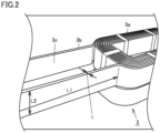
Fig. 2 is a schematic partial perspective view of an example of a coil that is an example of an object to be resin-molded by the resin molding apparatus according to the embodiment. -
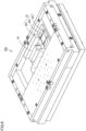
Fig. 3 is a schematic perspective view of an example of a lower mold of the resin molding apparatus according to the embodiment. -
Fig. 4 is a schematic plan perspective view of an example of a terminal accommodation unit, as viewed from above, before an elastic resin shown inFig. 3 is positionally fixed. -
Fig. 5 is a schematic plan perspective view of the example of the terminal accommodation unit, as viewed from above, when the elastic resin shown inFig. 3 is positionally fixed. -
Fig. 6 is a schematic perspective view of an example of an upper mold used for the resin molding apparatus according to the embodiment. -
Fig. 7 is a schematic plan view for illustrating an example of a process for resin-molding an object to be molded after the upper mold and the lower mold are clamped together. -
Fig. 8 is a schematic perspective view of an example of a resin molded product manufactured by the resin molding apparatus according to the embodiment. - Hereinafter, an embodiment will be described. In the figures used for describing the embodiment, identical reference characters denote identical or corresponding parts.
-
Fig. 1 is a schematic plan view of an example of a resin molding system comprising a resin molding apparatus according to an embodiment. Aresin molding system 100 comprises aresin molding apparatus 20 including a mold composed of an upper mold and alower mold 20b described later. Resinmolding apparatus 20 uses the mold to enable resin molding acoil 3, which is an example of an object to be molded. Resinmolding apparatus 20 comprises a transfer mechanism having a plunger to supply resin from apot 39 to a cavity, and amold clamping mechanism 48. -
Resin molding system 100 comprises, in addition to resinmolding apparatus 20, a CPU 1 serving as a central control device, astorage unit 8 that stores a control program and control information such as a procedure of a process for stoppingresin molding system 100, a drive mechanism that drives each unit described later, and a touch panel 9 (an example of an input unit) that receives input of an operation command and error processing related-information from a user and displays a variety of types of output information ofresin molding system 100. CPU 1 executes a program or the like stored instorage unit 8 to implement acontrol unit 10 that controls an operation of each unit ofresin molding system 100, anerror detection unit 11 that detects an error of the drive mechanism, and atimer unit 12 that counts elapse of time. -
Resin molding system 100 is configured by connecting an in module M1 having an inmagazine 7 and the like to accommodate a plurality ofcoils 3, a mold module M2 havingresin molding apparatus 20, and an out module M3 having an outmagazine 72 to accommodate a resin moldedproduct 31 manufactured byresin molding apparatus 20. In module M1, mold module M2, and out module M3 are each provided with a guide G linearly disposed across the module. Guide G is a member in the form of a rail to move aloader 40 and anunloader 44 described later. Whileresin molding system 100 shown inFig. 1 comprises two mold modules M2,resin molding system 100 may comprise only one mold module M2 or three or more mold modules M2. - The drive mechanism of
resin molding system 100 may include, for example,loader 40, afeeding unit 42, andunloader 44. Loader 40 is a transport mechanism to load an object to be molded 3 intoresin molding apparatus 20.Feeding unit 42 is a transport mechanism to pushcoil 3 out of inmagazine 7 and transport the coil to analignment mechanism 70.Unloader 44 is a transport mechanism to unload resin moldedproduct 31 fromresin molding apparatus 20. -
Fig. 2 is a schematic partial perspective view ofcoil 3 as an example of an object to be molded that is used for resin molding by resinmolding apparatus 20 according to the embodiment. As shown inFig. 2 ,coil 3 as an example of an object to be molded comprises abody 3a and aterminal 3b having a rectangularflat surface 3c extending from one end ofbody 3a in one direction. In the present specification, a "flat surface" means one of two planes thatterminal 3b comprises and are orthogonal to (or intersect) a direction in whichterminal 3b extends, for example as shown inFig. 2 . More specifically, the "flat surface" means one of these two planes that has a larger length in a direction orthogonal to the direction in whichterminal 3b extends. Further, in the present specification, a "thickness of the terminal" means a shortest length that defines an area of a surface having a smallest area among thesurfaces constituting terminal 3b. - A ratio of a longer one of lengths L1 and L2 of
terminal 3b to a thickness t ofterminal 3b (i.e., (larger one of lengths L1 and L2 [mm])/(thickness t [mm])) can for example be 2 or more and 80 or less. For example,terminal 3b can have thickness t of about 1.4 mm.Terminal 3b can have length L1 for example of about 50 mm.Terminal 3b can have length L2 for example of about 16 mm. -
Fig. 3 is a schematic perspective view of an example oflower mold 20b ofresin molding apparatus 20 according to the embodiment. The example shown inFig. 3 showslower mold 20b ofresin molding apparatus 20 with theFig. 2 coil 3 set. As shown inFig. 3 ,coil 3 is set inlower mold 20b such that adirection 3f orthogonal to adirection 3e in whichflat surface 3c ofterminal 3b ofcoil 3 extends is perpendicular to amold surface 22d oflower mold 20b. - As shown in
Fig. 3 ,lower mold 20b comprises acavity block 21 having formed therein a cavity that is a recess to accommodatebody 3a ofcoil 3, and aterminal accommodation unit 200 to accommodate terminal 3b ofcoil 3. A portion ofcavity block 21 closer to terminal accommodation unit 200 (hereinafter referred to as a "portion 21a of the cavity block") has a height equal to that of terminal accommodation unit 200 (a length in a direction parallel to the flat surface ofterminal 3b).Portion 21a of the cavity block has afirst slit 22a formed therethrough, as described later. While in thepresent embodiment portion 21a of the cavity block havingfirst slit 22a formed therethrough andcavity block 21 having a cavity formed therein are configured as discrete components, they may be formed in one piece.Terminal accommodation unit 200 compriseselastic resin 4 and aterminal arrangement block 23.Elastic resin 4 is located between cavity block 21 (orportion 21a of the cavity block) andterminal arrangement block 23. - Further, as shown in
Fig. 3 ,portion 21a ofcavity block 21 in contact withterminal accommodation unit 200,elastic resin 4, andterminal arrangement block 23 are provided with aslit 22 extending in a predetermined direction (in the present embodiment, linearly extending in onedirection 3e in whichflat surface 3c extends).Slit 22 includes afirst slit 22a provided throughportion 21a of the cavity block, asecond slit 22c provided throughterminal arrangement block 23, and athird slit 22b provided throughelastic resin 4. In the present embodiment,first slit 22a,second slit 22c, andthird slit 22b each linearly extend from a side ofcavity block 21 having a cavity formed therein indirection 3e in whichflat surface 3c ofterminal 3b ofcoil 3 extends. -
Slit 22 has a wall surface (including a wall surface offirst slit 22a, a wall surface ofsecond slit 22c, and a wall surface ofthird slit 22b) facingflat surface 3c of terminal 3b ofcoil 3 so that terminal 3b ofcoil 3 can be accommodated inslit 22. Note that the wall surface offirst slit 22a is configured by those surfaces ofportion 21a of the cavity block which mutually face alongdirection 3e in whichfirst slit 22a extends. The wall surface ofsecond slit 22c is configured by those surfaces ofterminal arrangement block 23 which mutually face alongdirection 3e in whichsecond slit 22c extends. The wall surface ofthird slit 22b is configured by those surfaces ofelastic resin 4 which mutually face alongdirection 3e in whichthird slit 22b extends. -
Elastic resin 4 can include an elastically deformable resin such as silicone rubber and a fluorine-containing resin (or fluororesin). It is more preferable to include a fluororesin capable of enduring high temperature and high pressure during resin molding. Examples of the fluororesin include polytetrafluoroethylene (PTFE), tetrafluoroethylene-perfluoroalkyl vinyl ether copolymer (PFA), tetrafluoroethylene-hexafluoropropylene copolymer (FEP), tetrafluoroethylene-ethylene copolymer (ETFE), and rubber containing fluorine atoms (FKM, FPM, FEPM, FFKM, and the like).Cavity block 21 andterminal arrangement block 23 can include metal for example. -
Fig. 4 is a schematic plan perspective view of an example ofterminal accommodation unit 200, as viewed from above, beforeelastic resin 4 shown inFig. 3 is positionally fixed. In theFig. 4 plan view,terminal arrangement block 23 is configured to surroundelastic resin 4 in a form of the letter U. That is, in the plan view,elastic resin 4 in the form of a rectangle has three sides surrounded byterminal arrangement block 23, and has the remaining oneside facing portion 21a in the form of a rectangle of the cavity block. - Further, as shown in
Fig. 4 ,terminal accommodation unit 200 further comprises apressing plate 24 betweenelastic resin 4 andterminal arrangement block 23. Pressingplate 24 is configured to be movable indirection 3e in which slit 22 extends, and is configured to be capable of pressingelastic resin 4 as pressingplate 24 moves. Pressingplate 24 is also provided with a slit (afourth slit 24a) indirection 3e in which slit 22 extends.Fourth slit 24a can have a width set to be equal a width d3 ofsecond slit 22c described later. - Further, as shown in
Fig. 4 ,terminal arrangement block 23 is provided with a throughhole 26 penetratingterminal arrangement block 23 indirection 3e in which slit 22 extends.Terminal accommodation unit 200 further comprises a pressingmember 25 configured to be movable through throughhole 26 indirection 3e in which slit 22 extends. Pressingmember 25 is configured to be capable of pressing pressingplate 24 indirection 3e in which slit 22 extends. - Pressing
member 25 can for example be a fastening member such as a male screw. When a male screw is used as pressingmember 25, for example, internally threading throughhole 26 allows pressingmember 25 to be fitted into throughhole 26 and rotated and thus moved toward pressingplate 24 indirection 3e in which slit 22 extends. Then, as shown in theFig. 5 schematic plan view, pressingmember 25 proceeds and has a tip exposed from one end of throughhole 26 to press pressingplate 24 at a point, and pressingplate 24 can in turn presselastic resin 4 againstcavity block 21 in a plane. Thus, in the present embodiment, pressingplate 24 can presselastic resin 4 againstcavity block 21 in a plane as uniformly as possible to positionally fixelastic resin 4. - As resin molding is repeatedly performed, it is necessary to replace
elastic resin 4 with another. To do so, contrary to the above, for example as shown inFig. 4 , pressingmember 25 can be rotated and thus moved in a direction away from pressingplate 24. Thus, pressingmember 25 no longer presses pressingplate 24 and pressingplate 24 hence no longer presseselastic resin 4 againstcavity block 21. Subsequently,elastic resin 4 is removed fromterminal accommodation unit 200, and a replacementelastic resin 4 is set, and positionally fixed in a method similar to that described above. Thus, in the present embodiment,elastic resin 4 can be replaced while the mold is attached toresin molding apparatus 20. -
Third slit 22b can have a width d2, as shown inFigs. 4 and 5 , which can be smaller than a width d1 offirst slit 22a.Third slit 22b having width d2 smaller than width d1 offirst slit 22a can more effectively suppress leakage and hence adhesion of resin to terminal 3b while the object to be molded is resin-molded. Further,second slit 22c can have width d3 equal to or larger than width d2 ofthird slit 22b. Further,second slit 22c can have width d3 larger than width d1 offirst slit 22a.Second slit 22c having larger width d3 allowscoil 3 to be set inlower mold 20b without terminal 3b having a tip in contact withlower mold 20b and can thus protectlower mold 20b against damage. Width d1 offirst slit 22a, width d3 ofsecond slit 22c, and width d2 ofthird slit 22b are widths in a direction perpendicular todirection 3e in which slit 22 extends and parallel tomold surface 22d oflower mold 20b. -
Fig. 6 is a schematic perspective view of an example of an upper mold used forresin molding apparatus 20 according to the embodiment. As shown inFig. 6 , anupper mold 20a comprises acavity block 33 having a cavity formed therein to accommodatebody 3a ofcoil 3, and aslit 32 to accommodate terminal 3b ofcoil 3.Upper mold 20a has the cavity at a location corresponding to the cavity oflower mold 20b.Upper mold 20a has slit 32 at a location corresponding to slit 22 oflower mold 20b.Slit 32 ofupper mold 20a may comprise afirst slit 32a provided at a location corresponding tofirst slit 22a oflower mold 20b, athird slit 32b provided at a location corresponding tothird slit 22b oflower mold 20b, and asecond slit 32c provided at a location corresponding tosecond slit 22c oflower mold 20b. - While in the present embodiment
lower mold 20b has the configuration shown inFigs. 3 to 5 andupper mold 20a has the configuration shown inFig. 6 ,lower mold 20b may have the configuration shown inFig. 6 andupper mold 20a may have the configuration shown inFigs. 3 to 5 . That is, one ofupper mold 20a andlower mold 20b can have the configuration shown inFigs. 3 to 5 . - In the present embodiment,
lower mold 20b has slit 22, andupper mold 20a has slit 32. In that case, a slit for accommodating terminal 3b ofcoil 3 is divided and thus formed in the upper and lower molds, which is advantageous in thatterminal 3b is easily inserted into and thus disposed in the slit when terminal 3b has a large length L2 (orflat surface 3c has a large width) or terminal 3b has a large length L1 (orflat surface 3c has a large length). However, slit 32 ofupper mold 20a is not essential, and the slit for accommodating terminal 3b ofcoil 3 may be formed only inlower mold 20b. - Subsequently, for example as shown in a schematic plan view of
Fig. 7 ,upper mold 20a andlower mold 20b are clamped together, and thereafter,coil 3 is resin-molded. Thereafter,upper mold 20a andlower mold 20b are unclamped, and resin moldedproduct 31 as shown in a schematic perspective view ofFig. 8 can be manufactured. - In the present embodiment,
body 3a ofcoil 3 of resin moldedproduct 31 can be coated with resin while terminal 3b havingflat surface 3c extending from one end ofbody 3a can be prevented from being coated with resin. For this, in the present embodiment, by pressingelastic resin 4 againstportion 21a of the cavity block, the elastic force ofelastic resin 4 can be utilized to bringelastic resin 4 into close contact withportion 21a of the cavity block. Further, the elastic force ofelastic resin 4 can also be utilized to bringelastic resin 4 into close contact with terminal 3b. Thus, in the present embodiment,body 3a ofcoil 3 can be resin-molded whileelastic resin 4 andportion 21a of the cavity block are in close contact with each other andelastic resin 4 and terminal 3b are in close contact with each other, and this can suppress leakage of resin to a side outer thanportion 21a of the cavity block (or toward terminal arrangement block 23). Thus, in the present embodiment, leakage and hence adhesion of resin to terminal 3b ofcoil 3 as an object to be molded can be suppressed even when resin molding is performed whilecoil 3 is set in the mold such thatdirection 3f orthogonal todirection 3e in which theterminal 3bflat surface 3c extending from one end ofbody 3a ofcoil 3 extends is perpendicular to a mold surface of the mold. - Further, in the present embodiment, for example when the above-mentioned fluororesin is used as
elastic resin 4, terminal 3b can be smoothly inserted into and disposed inthird slit 22b provided throughelastic resin 4. Further, in the present embodiment, for example as described above,elastic resin 4 can also be replaced while the mold is attached toresin molding apparatus 20. - A mold according to Disclosure 1 is a mold used to resin-mold an object to be molded, the object comprising a body and a terminal having a flat surface extending from one end of the body, that is used to perform resin-molding while the object to be molded is set such that a direction orthogonal to a direction in which the flat surface extends is perpendicular to a mold surface of the mold, the mold comprising an upper mold and a lower mold, either one of the upper mold or the lower mold comprising a cavity block having a cavity formed therein to accommodate the body, and a terminal accommodation unit to accommodate the terminal, the terminal accommodation unit comprising a terminal arrangement block and an elastic resin between the cavity block and the terminal arrangement block, the terminal accommodation unit having a slit.
- A mold of Disclosure 2 is the mold of Disclosure 1, wherein the elastic resin includes a fluororesin.
- A mold of
Disclosure 3 is the mold of Disclosure 1 or 2, wherein one of the upper and lower molds is the lower mold. - A mold of
Disclosure 4 is the mold of any one of Disclosures 1 to 3, wherein the terminal arrangement block is configured to surround the elastic resin in a form of the letter U in a plan view. - A mold of Disclosure 5 is the mold of
Disclosure 4, wherein the terminal accommodation unit further comprises a pressing plate between the elastic resin and the terminal arrangement block, and the pressing plate is movable in a direction in which the slit extends, and configured to be capable of pressing the elastic resin as the pressing plate moves. - A mold of Disclosure 6 is the mold of Disclosure 5, wherein the terminal arrangement block is provided with a through hole penetrating the terminal arrangement block in the direction in which the slit extends, the terminal accommodation unit further comprises a pressing member configured to be movable through the through hole in the direction in which the slit extends, and the pressing member is configured to be capable of pressing the pressing plate in the direction in which the slit extends.
- A mold of
Disclosure 7 is the mold of Disclosure 6, wherein the pressing plate is configured to be capable of pressing the elastic resin in a plane, and the pressing member is configured to be capable of pressing the pressing plate at a point. - A mold of
Disclosure 8 is the mold ofDisclosure 6 or 7, wherein the through hole is internally threaded and the pressing member is externally threaded, and the pressing member is configured to be movable through the through hole as the pressing member is rotated. - A mold of
Disclosure 9 is the mold of any one of Disclosures 1 to 8, wherein the slit includes a first slit provided through the cavity block, a second slit provided through the terminal arrangement block, and a third slit provided through the elastic resin. - A mold of
Disclosure 10 is the mold ofDisclosure 9, wherein the third slit is smaller in width than the first slit. - A mold of
Disclosure 11 is the mold ofDisclosure - A resin molding apparatus of
Disclosure 12 is a resin molding apparatus comprising a mold of any one of Disclosures 1 to 11. - A resin molding system of Disclosure 13 is a resin molding system comprising the resin molding apparatus of
Disclosure 12. - While embodiments have thus been described, it is also initially planned to combine the configuration of each embodiment described above with another, as appropriate.
- It should be understood that the embodiments disclosed herein are illustrative and in a non-restrictive manner in any respect. The scope of the present invention is defined by the terms of the claims, rather than the description above, and is intended to encompass any modifications within the meaning and scope equivalent to the terms of the claims.
- 1 CPU, 3 coil, 3a body, 3b terminal, 3c flat surface, 4 elastic resin, 7 in magazine, 8 storage unit, 9 touch panel, 10 control unit, 11 error detection unit, 12 timer unit, 20 resin molding apparatus, 20a upper mold, 20b lower mold, 21, 33 cavity block, 21a portion of cavity block, 22, 32 slit, 22a, 32a first slit, 22b, 32b third slit, 22c, 32c second slit, 22d mold surface, 23 terminal arrangement block, 24 pressing plate, 24a fourth slit, 25 pressing member, 26 through hole, 31 resin molded product, 39 pot, 40 loader, 42 feeding unit, 44 unloader, 48 mold clamping mechanism, 70 alignment mechanism, 72 out magazine, 100 resin molding system, 200 terminal accommodation unit.
Claims (9)
- A mold used to resin-mold an object to be molded, the object comprising a body and a terminal having a flat surface extending from one end of the body, that is used to perform resin-molding while the object to be molded is set such that a direction orthogonal to a direction in which the flat surface extends is perpendicular to a mold surface of the mold,the mold comprising an upper mold and a lower mold,one of the upper mold and the lower mold comprisinga cavity block having a cavity formed therein to accommodate the body, and a terminal accommodation unit to accommodate the terminal,the terminal accommodation unit comprising a terminal arrangement block and an elastic resin between the cavity block and the terminal arrangement block,the terminal accommodation unit having a slit.
- The mold according to claim 1, wherein the elastic resin includes a fluororesin.
- The mold according to claim 1 or 2, wherein one of the upper and lower molds is the lower mold.
- The mold according to any one of claims 1 to 3, wherein the terminal arrangement block is configured to surround the elastic resin in a form of a letter U in plan view.
- The mold according to claim 4, whereinthe terminal accommodation unit further comprises a pressing plate between the elastic resin and the terminal arrangement block, andthe pressing plate is movable in a direction in which the slit extends, and configured to be capable of pressing the elastic resin as the pressing plate moves.
- The mold according to claim 5, whereinthe terminal arrangement block is provided with a through hole penetrating the terminal arrangement block in the direction in which the slit extends,the terminal accommodation unit further comprises a pressing member configured to be movable through the through hole in the direction in which the slit extends, andthe pressing member is configured to be capable of pressing the pressing plate in the direction in which the slit extends.
- The mold according to any one of claims 1 to 6, wherein the slit further includes a first slit provided through the cavity block, and the elastic resin is provided with a third slit smaller in width than the first slit.
- A resin molding apparatus comprising the mold according to any one of claims 1 to 7.
- A resin molding system comprising the resin molding apparatus according to claim 8.
Applications Claiming Priority (2)
| Application Number | Priority Date | Filing Date | Title |
|---|---|---|---|
| JP2022090016A JP7691396B2 (en) | 2022-06-02 | 2022-06-02 | Mold, resin molding device, and resin molding system |
| PCT/JP2023/004132 WO2023233712A1 (en) | 2022-06-02 | 2023-02-08 | Molding die, resin molding apparatus, and resin molding system |
Publications (2)
| Publication Number | Publication Date |
|---|---|
| EP4512598A1 true EP4512598A1 (en) | 2025-02-26 |
| EP4512598A4 EP4512598A4 (en) | 2026-04-22 |
Family
ID=89025970
Family Applications (1)
| Application Number | Title | Priority Date | Filing Date |
|---|---|---|---|
| EP23815476.9A Pending EP4512598A4 (en) | 2022-06-02 | 2023-02-08 | Molding tool, resin molding device and resin molding system |
Country Status (6)
| Country | Link |
|---|---|
| EP (1) | EP4512598A4 (en) |
| JP (1) | JP7691396B2 (en) |
| KR (1) | KR20240159947A (en) |
| CN (1) | CN119053426A (en) |
| TW (1) | TWI861849B (en) |
| WO (1) | WO2023233712A1 (en) |
Family Cites Families (9)
| Publication number | Priority date | Publication date | Assignee | Title |
|---|---|---|---|---|
| JPS5430256A (en) * | 1977-08-12 | 1979-03-06 | Sumida Electric | Manufacture of resin molded coil |
| JPS577898A (en) | 1980-06-12 | 1982-01-16 | Fujitsu Ltd | Liquid phase epitaxial growing method |
| JPS6293879A (en) * | 1985-10-19 | 1987-04-30 | オムロン株式会社 | Manufacture of self-supporting terminal of electric machine |
| US4732553A (en) * | 1987-07-06 | 1988-03-22 | Libbey-Owens-Ford Co. | Seal construction for a mold structure for encapsulating glass with a gasket |
| JP2596612B2 (en) * | 1988-08-09 | 1997-04-02 | 旭硝子株式会社 | Manufacturing method of window glass with gasket and molding die |
| US5609652A (en) | 1994-04-13 | 1997-03-11 | Koito Manufacturing Co., Ltd. | Method of manufacturing a synthetic resin part integrally formed with metal members |
| JP2001237022A (en) * | 2000-02-25 | 2001-08-31 | Kitani Denki Kk | Power plug and method of manufacturing the same |
| JP3411900B2 (en) | 2000-11-15 | 2003-06-03 | 東海興業株式会社 | Molding method of connector integrated case |
| JP2003234144A (en) * | 2001-12-04 | 2003-08-22 | Auto Network Gijutsu Kenkyusho:Kk | connector |
-
2022
- 2022-06-02 JP JP2022090016A patent/JP7691396B2/en active Active
-
2023
- 2023-02-08 CN CN202380034179.XA patent/CN119053426A/en active Pending
- 2023-02-08 KR KR1020247033715A patent/KR20240159947A/en active Pending
- 2023-02-08 EP EP23815476.9A patent/EP4512598A4/en active Pending
- 2023-02-08 WO PCT/JP2023/004132 patent/WO2023233712A1/en not_active Ceased
- 2023-04-28 TW TW112116099A patent/TWI861849B/en active
Also Published As
| Publication number | Publication date |
|---|---|
| JP2023177390A (en) | 2023-12-14 |
| CN119053426A (en) | 2024-11-29 |
| TWI861849B (en) | 2024-11-11 |
| JP7691396B2 (en) | 2025-06-11 |
| EP4512598A4 (en) | 2026-04-22 |
| KR20240159947A (en) | 2024-11-07 |
| WO2023233712A1 (en) | 2023-12-07 |
| TW202349515A (en) | 2023-12-16 |
Similar Documents
| Publication | Publication Date | Title |
|---|---|---|
| US10749147B2 (en) | Pouch forming device and method and facility for producing secondary battery comprising the pouch forming device | |
| EP3229266A1 (en) | Resin molding device and resin molding method | |
| JP2013028087A (en) | Molding die set, and resin molding apparatus having the same | |
| US20210387385A1 (en) | Conveying apparatus, resin molding apparatus, conveying method, and resin molded product manufacturing method | |
| WO2016203784A1 (en) | Molding die, resin molding device, and resin molding method | |
| WO2022224487A1 (en) | Molding die, resin molding device, and method for manufacturing resin molded article | |
| EP2891808B1 (en) | System for coupling a semiconductor device of an automation device to a heat sink | |
| JP7691396B2 (en) | Mold, resin molding device, and resin molding system | |
| WO2024014060A1 (en) | Mold, device for molding resin, and method for producing molded resin article | |
| KR20180015568A (en) | Mold, resin molding apparatus and method for manufacturing resin molded article | |
| KR20160133468A (en) | Resin molding method and resin molding die set | |
| US20210268702A1 (en) | Injection molding die, and method of manufacturing molded product | |
| KR102682318B1 (en) | Lubrication system for injection molding machine and control method thereof | |
| JP2014138127A (en) | Resin sealing device | |
| TW202346106A (en) | Method for manufacturing resin-molded article | |
| CN214772123U (en) | Clamping device, positioning jig and assembly line | |
| JP5694486B2 (en) | Resin sealing device | |
| JP2002321239A (en) | Resin sealing device | |
| CN110662703B (en) | Method for manufacturing carrier tape for electronic parts | |
| JP2007119011A (en) | Manufacturing method and manufacturing equipment for embossed carrier tape | |
| JP6253309B2 (en) | Attaching multiple members | |
| JP5302104B2 (en) | Metal plate insertion method, insertion device and assembly manufacturing method | |
| CN119408835B (en) | A packaging box | |
| CN113910515B (en) | Device and method for reinforcing heat dissipation gasket in power module | |
| US10833445B1 (en) | Cable connector housing attachment for protecting and directing a cable |
Legal Events
| Date | Code | Title | Description |
|---|---|---|---|
| STAA | Information on the status of an ep patent application or granted ep patent |
Free format text: STATUS: THE INTERNATIONAL PUBLICATION HAS BEEN MADE |
|
| PUAI | Public reference made under article 153(3) epc to a published international application that has entered the european phase |
Free format text: ORIGINAL CODE: 0009012 |
|
| STAA | Information on the status of an ep patent application or granted ep patent |
Free format text: STATUS: REQUEST FOR EXAMINATION WAS MADE |
|
| 17P | Request for examination filed |
Effective date: 20241121 |
|
| AK | Designated contracting states |
Kind code of ref document: A1 Designated state(s): AL AT BE BG CH CY CZ DE DK EE ES FI FR GB GR HR HU IE IS IT LI LT LU LV MC ME MK MT NL NO PL PT RO RS SE SI SK SM TR |
|
| DAV | Request for validation of the european patent (deleted) | ||
| DAX | Request for extension of the european patent (deleted) | ||
| A4 | Supplementary search report drawn up and despatched |
Effective date: 20260320 |
|
| RIC1 | Information provided on ipc code assigned before grant |
Ipc: B29C 45/14 20060101AFI20260316BHEP Ipc: B29C 45/36 20060101ALI20260316BHEP Ipc: B29C 33/12 20060101ALI20260316BHEP Ipc: B29C 45/00 20060101ALI20260316BHEP Ipc: B29C 45/02 20060101ALI20260316BHEP |