EP4512461A2 - System zur abgabe einer vorgeschriebenen neuromodulationsdosis - Google Patents
System zur abgabe einer vorgeschriebenen neuromodulationsdosis Download PDFInfo
- Publication number
- EP4512461A2 EP4512461A2 EP24210637.5A EP24210637A EP4512461A2 EP 4512461 A2 EP4512461 A2 EP 4512461A2 EP 24210637 A EP24210637 A EP 24210637A EP 4512461 A2 EP4512461 A2 EP 4512461A2
- Authority
- EP
- European Patent Office
- Prior art keywords
- stimulation
- patient
- external controller
- prescription
- amount
- Prior art date
- Legal status (The legal status is an assumption and is not a legal conclusion. Google has not performed a legal analysis and makes no representation as to the accuracy of the status listed.)
- Pending
Links
Images




Classifications
-
- A—HUMAN NECESSITIES
- A61—MEDICAL OR VETERINARY SCIENCE; HYGIENE
- A61N—ELECTROTHERAPY; MAGNETOTHERAPY; RADIATION THERAPY; ULTRASOUND THERAPY
- A61N1/00—Electrotherapy; Circuits therefor
- A61N1/18—Applying electric currents by contact electrodes
- A61N1/32—Applying electric currents by contact electrodes alternating or intermittent currents
- A61N1/36—Applying electric currents by contact electrodes alternating or intermittent currents for stimulation
- A61N1/372—Arrangements in connection with the implantation of stimulators
- A61N1/37211—Means for communicating with stimulators
- A61N1/37235—Aspects of the external programmer
- A61N1/37247—User interfaces, e.g. input or presentation means
-
- A—HUMAN NECESSITIES
- A61—MEDICAL OR VETERINARY SCIENCE; HYGIENE
- A61N—ELECTROTHERAPY; MAGNETOTHERAPY; RADIATION THERAPY; ULTRASOUND THERAPY
- A61N1/00—Electrotherapy; Circuits therefor
- A61N1/18—Applying electric currents by contact electrodes
- A61N1/32—Applying electric currents by contact electrodes alternating or intermittent currents
- A61N1/36—Applying electric currents by contact electrodes alternating or intermittent currents for stimulation
- A61N1/3605—Implantable neurostimulators for stimulating central or peripheral nerve system
- A61N1/3606—Implantable neurostimulators for stimulating central or peripheral nerve system adapted for a particular treatment
- A61N1/36062—Spinal stimulation
-
- A—HUMAN NECESSITIES
- A61—MEDICAL OR VETERINARY SCIENCE; HYGIENE
- A61N—ELECTROTHERAPY; MAGNETOTHERAPY; RADIATION THERAPY; ULTRASOUND THERAPY
- A61N1/00—Electrotherapy; Circuits therefor
- A61N1/18—Applying electric currents by contact electrodes
- A61N1/32—Applying electric currents by contact electrodes alternating or intermittent currents
- A61N1/36—Applying electric currents by contact electrodes alternating or intermittent currents for stimulation
- A61N1/3605—Implantable neurostimulators for stimulating central or peripheral nerve system
- A61N1/3606—Implantable neurostimulators for stimulating central or peripheral nerve system adapted for a particular treatment
- A61N1/36071—Pain
-
- A—HUMAN NECESSITIES
- A61—MEDICAL OR VETERINARY SCIENCE; HYGIENE
- A61N—ELECTROTHERAPY; MAGNETOTHERAPY; RADIATION THERAPY; ULTRASOUND THERAPY
- A61N1/00—Electrotherapy; Circuits therefor
- A61N1/02—Details
- A61N1/025—Digital circuitry features of electrotherapy devices, e.g. memory, clocks, processors
-
- A—HUMAN NECESSITIES
- A61—MEDICAL OR VETERINARY SCIENCE; HYGIENE
- A61N—ELECTROTHERAPY; MAGNETOTHERAPY; RADIATION THERAPY; ULTRASOUND THERAPY
- A61N1/00—Electrotherapy; Circuits therefor
- A61N1/02—Details
- A61N1/04—Electrodes
- A61N1/05—Electrodes for implantation or insertion into the body, e.g. heart electrode
- A61N1/0551—Spinal or peripheral nerve electrodes
-
- A—HUMAN NECESSITIES
- A61—MEDICAL OR VETERINARY SCIENCE; HYGIENE
- A61N—ELECTROTHERAPY; MAGNETOTHERAPY; RADIATION THERAPY; ULTRASOUND THERAPY
- A61N1/00—Electrotherapy; Circuits therefor
- A61N1/18—Applying electric currents by contact electrodes
- A61N1/32—Applying electric currents by contact electrodes alternating or intermittent currents
- A61N1/36—Applying electric currents by contact electrodes alternating or intermittent currents for stimulation
- A61N1/3605—Implantable neurostimulators for stimulating central or peripheral nerve system
- A61N1/36128—Control systems
- A61N1/36135—Control systems using physiological parameters
-
- A—HUMAN NECESSITIES
- A61—MEDICAL OR VETERINARY SCIENCE; HYGIENE
- A61N—ELECTROTHERAPY; MAGNETOTHERAPY; RADIATION THERAPY; ULTRASOUND THERAPY
- A61N1/00—Electrotherapy; Circuits therefor
- A61N1/18—Applying electric currents by contact electrodes
- A61N1/32—Applying electric currents by contact electrodes alternating or intermittent currents
- A61N1/36—Applying electric currents by contact electrodes alternating or intermittent currents for stimulation
- A61N1/3605—Implantable neurostimulators for stimulating central or peripheral nerve system
- A61N1/36128—Control systems
- A61N1/36146—Control systems specified by the stimulation parameters
- A61N1/36182—Direction of the electrical field, e.g. with sleeve around stimulating electrode
- A61N1/36185—Selection of the electrode configuration
-
- A—HUMAN NECESSITIES
- A61—MEDICAL OR VETERINARY SCIENCE; HYGIENE
- A61N—ELECTROTHERAPY; MAGNETOTHERAPY; RADIATION THERAPY; ULTRASOUND THERAPY
- A61N1/00—Electrotherapy; Circuits therefor
- A61N1/18—Applying electric currents by contact electrodes
- A61N1/32—Applying electric currents by contact electrodes alternating or intermittent currents
- A61N1/36—Applying electric currents by contact electrodes alternating or intermittent currents for stimulation
- A61N1/372—Arrangements in connection with the implantation of stimulators
- A61N1/37211—Means for communicating with stimulators
- A61N1/37235—Aspects of the external programmer
- A61N1/37241—Aspects of the external programmer providing test stimulations
Definitions
- This application relates to Implantable Medical Devices (IMDs), generally, Spinal Cord Stimulators, more specifically, and to methods of control of such devices.
- IMDs Implantable Medical Devices
- Spinal Cord Stimulators Spinal Cord Stimulators
- Implantable neurostimulator devices are devices that generate and deliver electrical stimuli to body nerves and tissues for the therapy of various biological disorders, such as pacemakers to treat cardiac arrhythmia, defibrillators to treat cardiac fibrillation, cochlear stimulators to treat deafness, retinal stimulators to treat blindness, muscle stimulators to produce coordinated limb movement, spinal cord stimulators to treat chronic pain, cortical and deep brain stimulators to treat motor and psychological disorders, and other neural stimulators to treat urinary incontinence, sleep apnea, shoulder subluxation, etc.
- SCS Spinal Cord Stimulation
- the present invention may find applicability with any implantable neurostimulator device system.
- An SCS system typically includes an Implantable Pulse Generator (IPG) 10 shown in Figure 1 .
- the IPG 10 includes a biocompatible device case 12 that holds the circuitry and battery 14 necessary for the IPG to function.
- the IPG 10 is coupled to electrodes 16 via one or more electrode leads 15 that form an electrode array 17.
- the electrodes 16 are configured to contact a patient's tissue and are carried on a flexible body 18, which also houses the individual lead wires 20 coupled to each electrode 16.
- the lead wires 20 are also coupled to proximal contacts 22, which are insertable into lead connectors 24 fixed in a header 23 on the IPG 10, which header can comprise an epoxy for example. Once inserted, the proximal contacts 22 connect to header contacts within the lead connectors 24, which are in turn coupled by feedthrough pins through a case feedthrough to circuitry within the case 12, although these details aren't shown.
- the conductive case 12 can also comprise an electrode (Ec).
- Ec an electrode
- the electrode leads 15 are typically implanted proximate to the dura in a patient's spinal column on the right and left sides of the spinal cord midline.
- the proximal electrodes 22 are tunneled through the patient's tissue to a distant location such as the buttocks where the IPG case 12 is implanted, at which point they are coupled to the lead connectors 24.
- the IPG can be lead-less, having electrodes 16 instead appearing on the body of the IPG for contacting the patient's tissue.
- the IPG leads 15 can be integrated with and permanently connected the case 12 in other IPG solutions.
- the goal of SCS therapy is to provide electrical stimulation from the electrodes 16 to alleviate a patient's symptoms, most notably chronic back pain.
- IPG 10 can include an antenna 26a allowing it to communicate bi-directionally with a number of external devices, as shown in Figure 4 .
- the antenna 26a as depicted in Figure 1 is shown as a conductive coil within the case 12, although the coil antenna 26a can also appear in the header 23.
- IPG may also include a RadioFrequency (RF) antenna 26b.
- RF antenna 26b is shown within the header 23, but it may also be within the case 12.
- RF antenna 26b may comprise a patch, slot, or wire, and may operate as a monopole or dipole.
- RF antenna 26b preferably communicates using far-field electromagnetic waves.
- RF antenna 26b may operate in accordance with any number of known RF communication standards, such as Bluetooth, Zigbee, WiFi, MICS, and the like.
- Stimulation in IPG 10 is typically provided by pulses, as shown in Figure 2 .
- Stimulation parameters typically include the amplitude of the pulses (A; whether current or voltage); the frequency (F) and pulse width (PW) of the pulses; the electrodes 16 (E) activated to provide such stimulation; and the polarity (P) of such active electrodes, i.e., whether active electrodes are to act as anodes (that source current to the tissue) or cathodes (that sink current from the tissue).
- Stimulation parameters taken together comprise a stimulation program that the IPG 10 can execute to provide therapeutic stimulation to a patient.
- electrode E5 has been selected as an anode, and thus provides pulses which source a positive current of amplitude +A to the tissue.
- Electrode E4 has been selected as a cathode, and thus provides pulses which sink a corresponding negative current of amplitude -A from the tissue.
- This is an example of bipolar stimulation, in which only two lead-based electrodes are used to provide stimulation to the tissue (one anode, one cathode). However, more than one electrode may act as an anode at a given time, and more than one electrode may act as a cathode at a given time (e.g., tripole stimulation, quadripole stimulation, etc.).
- each electrodes' current path to the tissue may include a serially-connected DC-blocking capacitor, see, e.g., U.S. Patent Application Publication 2016/0144183 , which will charge during the first phase 30a and discharged (be recovered) during the second phase 30b.
- the first and second phases 30a and 30b have the same duration and amplitude (although opposite polarities), which ensures the same amount of charge during both phases.
- the second phase 30b may also be charged balance with the first phase 30a if the integral of the amplitude and durations of the two phases are equal in magnitude, as is well known.
- the width of each pulse, PW is defined here as the duration of first pulse phase 30a, although pulse width could also refer to the total duration of the first and second pulse phases 30a and 30b as well.
- IP interphase period
- IPG 10 includes stimulation circuitry 28 that can be programmed to produce the stimulation pulses at the electrodes as defined by the stimulation program.
- the IPG 10 acts as a power supply to deliver power to the electrodes for providing stimulation to the patient.
- Stimulation circuitry 28 can for example comprise the circuitry described in U.S. Patent Application Publications 2018/0071513 and 2018/0071520 , or described in USPs 8,606,362 and 8,620,436 . These references are incorporated herein by reference.
- FIG 3 shows an external trial stimulation environment that may precede implantation of an IPG 10 in a patient.
- stimulation can be tried on a prospective implant patient without going so far as to implant the IPG 10.
- one or more trial leads 15' are implanted in the patient's tissue 32 at a target location 34, such as within the spinal column as explained earlier.
- the proximal ends of the trial lead(s) 15' exit an incision 36 and are connected to an External Trial Stimulator (ETS) 40.
- ETS 40 External Trial Stimulator
- the ETS 40 generally mimics operation of the IPG 10, and thus can provide stimulation pulses to the patient's tissue as explained above. See, e.g., 9,259,574, disclosing a design for an ETS.
- the ETS 40 is generally worn externally by the patient for a short while (e.g., two weeks), which allows the patient and his clinician to experiment with different stimulation parameters to try and find a stimulation program that alleviates the patient's symptoms (e.g., pain). If external trial stimulation proves successful, trial lead(s) 15' are explanted, and a full IPG 10 and lead(s) 15 are implanted as described above; if unsuccessful, the trial lead(s) 15' are simply explanted.
- the ETS 40 can include one or more antennas to enable bi-directional communications with external devices, explained further with respect to Figure 4 .
- Such antennas can include a near-field magnetic-induction coil antenna 42a, and/or a far-field RF antenna 42b, as described earlier.
- ETS 40 may also include stimulation circuitry 44 able to form the stimulation pulses in accordance with a stimulation program, which circuitry may be similar to or comprise the same stimulation circuitry 28 present in the IPG 10.
- ETS 40 may also include a battery (not shown) for operational power.
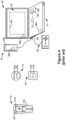
- Figure 4 shows various external devices that can wirelessly communicate data with the IPG 10 and the ETS 40, including a patient, hand-held external controller 45, and a clinician programmer 50.
- Both of devices 45 and 50 can be used to send a stimulation program to the IPG 10 or ETS 40-that is, to program their stimulation circuitries 28 and 44 to produce pulses with a desired shape and timing described earlier.
- Both devices 45 and 50 may also be used to adjust one or more stimulation parameters of a stimulation program that the IPG 10 or ETS 40 is currently executing.
- Devices 45 and 50 may also receive information from the IPG 10 or ETS 40, such as various status information, etc.
- External controller 45 can be as described in U.S. Patent Application Publication 2015/0080982 for example, and may comprise either a dedicated controller configured to work with the IPG 10. External controller 45 may also comprise a general purpose mobile electronics device such as a mobile phone which has been programmed with a Medical Device Application (MDA) allowing it to work as a wireless controller for the IPG 10 or ETS 40, as described in U.S. Patent Application Publication 2015/0231402 . External controller 45 includes a user interface, including means for entering commands (e.g., buttons or icons) and a display 46. The external controller 45's user interface enables a patient to adjust stimulation parameters, although it may have limited functionality when compared to the more-powerful clinician programmer 50, described shortly.
- MDA Medical Device Application
- the external controller 45 can have one or more antennas capable of communicating with the IPG 10 and ETS 40.
- the external controller 45 can have a near-field magnetic-induction coil antenna 47a capable of wirelessly communicating with the coil antenna 26a or 42a in the IPG 10 or ETS 40.
- the external controller 45 can also have a far-field RF antenna 47b capable of wirelessly communicating with the RF antenna 26b or 42b in the IPG 10 or ETS 40.
- the external controller 45 can also have control circuitry 48 such as a microprocessor, microcomputer, an FPGA, other digital logic structures, etc., which is capable of executing instructions an electronic device.
- Control circuitry 48 can for example receive patient adjustments to stimulation parameters, and create a stimulation program to be wirelessly transmitted to the IPG 10 or ETS 40.
- the clinician programmer 50 can comprise a computing device 51, such as a desktop, laptop, or notebook computer, a tablet, a mobile smart phone, a Personal Data Assistant (PDA)-type mobile computing device, etc.
- computing device 51 is shown as a laptop computer that includes typical computer user interface means such as a screen 52, a mouse, a keyboard, speakers, a stylus, a printer, etc., not all of which are shown for convenience.
- accessory devices for the clinician programmer 50 that are usually specific to its operation as a stimulation controller, such as a communication "wand" 54, and a joystick 58, which are coupleable to suitable ports on the computing device 51, such as USB ports 59 for example.
- the antenna used in the clinician programmer 50 to communicate with the IPG 10 or ETS 40 can depend on the type of antennas included in those devices. If the patient's IPG 10 or ETS 40 includes a coil antenna 26a or 42a, wand 54 can likewise include a coil antenna 56a to establish near-filed magnetic-induction communications at small distances. In this instance, the wand 54 may be affixed in close proximity to the patient, such as by placing the wand 54 in a belt or holster wearable by the patient and proximate to the patient's IPG 10 or ETS 40.
- the wand 54, the computing device 51, or both can likewise include an RF antenna 56b to establish communication with the IPG 10 or ETS 40 at larger distances. (Wand 54 may not be necessary in this circumstance).
- the clinician programmer 50 can also establish communication with other devices and networks, such as the Internet, either wirelessly or via a wired link provided at an Ethernet or network port.
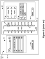
- GUI 64 A portion of the GUI 64 is shown in one example in Figure 5 .
- clinician programmer software 66 is in its execution, which will depend on the GUI selections the clinician has made.
- Stimulation parameters relating to the electrodes 16 are made adjustable in an electrode parameter interface 86. Electrode stimulation parameters are also visible and can be manipulated in a leads interface 92 that displays the leads 15 (or 15') in generally their proper position with respect to each other, for example, on the left and right sides of the spinal column. A cursor 94 (or other selection means such as a mouse pointer) can be used to select a particular electrode in the leads interface 92. Buttons in the electrode parameter interface 86 allow the selected electrode (including the case electrode, Ec) to be designated as an anode, a cathode, or off.
- GUI 64 is shown as operating in the clinician programmer 50, the user interface of the external controller 45 may provide similar functionality.
- FIG. 6 shows an alternative embodiment of an implantable SCS system 600 comprising an implanted electrode lead 602 having electrodes 16 disposed thereon.
- the SCS system 600 does not use an implanted IPG to provide power for electrical stimulation. Instead, power is provided via radio frequency (RF) transmission through the patient's tissue 32 from an external power supply (EPS) 604.
- RF radio frequency
- EPS external power supply
- the EPS has an RF antenna 606 configured to transmit RF power and the implanted lead 602 comprises an antenna 608 configured to receive the RF power.
- the implanted lead 602 also has simple circuitry (not shown) configured to rectify the RF power and generate pulses.
- the RF-powered system 600 may use an external controller 45 to control and transmit stimulation parameters.
- the external controller 45 provides stimulation parameters to the EPS 604, rather than to an implanted IPG. While the EPS 604 and the external controller 45 are illustrated as separate units in Figure 6 , the EPS 604 and the external controller 45 may be combined as a single unit.
- the illustrated SCS system 600 has an advantage over the system illustrated in Figure 1 in that the system 600 does not require a surgical procedure to implant an IPG (10, FIG. 1 ) and tunnel lead wires (20, FIG. 1 ) between the IPG and the electrode leads.
- a disadvantage of the system 600 ( FIG. 6 ) is that the patient must position the EPS 604 near their tissue any time that they wish to receive stimulation.
- the EPS 604 may be carried in a belt, pouch or other carrying device, for example. Systems as shown in Figure 6 , which rely on RF energy provided by an EPS are referred to herein as "RF systems.”
- a method of providing a prescribed amount of stimulation to a patient using an implantable stimulator device that is implantable in the patient and an external controller configured to control the implantable stimulator device comprises: receiving a prescription, wherein the prescription quantifies the prescribed amount of stimulation to be provided by the implantable stimulator device, using the external controller to instruct the implantable stimulator device to provide stimulation, tracking the provided stimulation and determine an amount of provided stimulation, determining a difference between the prescribed amount of stimulation and the amount of provided stimulation, wherein the difference indicates the amount of stimulation remaining on the prescription and/or an amount of the prescription used, and using the external controller to provide an indication of the difference.
- the prescribed amount of stimulation is based on a total amount of actively delivered charge to be delivered to the patient. According to some embodiments, the prescribed amount of stimulation is based on a total amount of time that stimulation is to be provided to the patient. According to some embodiments, the prescribed amount of stimulation is based on a total number of boluses of stimulation to be delivered to the patient. According to some embodiments, each bolus of stimulation comprises a specified duration during which stimulation is to be delivered to the patient. According to some embodiments, each bolus of stimulation comprises an amount of actively driven charge to be delivered to the patient. According to some embodiments, using the external controller to provide an indication of the difference comprises displaying an indication of the difference on a user interface of the external controller.
- using the external controller to provide an indication of the difference comprises sending a message to a remote location.
- receiving a prescription at the external controller comprises receiving the prescription from a clinician programmer.
- the steps of receiving a prescription, tracking the provided stimulation, and determining a difference between the prescribed amount of stimulation and the amount of provided stimulation are performed by the implantable stimulator device.
- the steps of receiving a prescription, tracking the provided stimulation, and determining a difference between the prescribed amount of stimulation and the amount of provided stimulation are performed by the external controller.
- determining the prescription for stimulation comprises: receiving a stimulation program comprising one or more parameters of a stimulation waveform, receiving one or more inputs indicating an amount of stimulation to be provided to the patient, and calculating the prescription for stimulation based on the stimulation program and the one or more inputs.
- the invention may also reside in the form of a programed external device (via its control circuitry) for carrying out the above methods, a programmed IPG or ETS (via its control circuitry) for carrying out the above methods, a system including a programmed external device and IPG or ETS for carrying out the above methods, or as a computer readable media for carrying out the above methods stored in an external device or IPG or ETS.
- a patient when a patient has been identified as a candidate for neuromodulation therapy, such as spinal cord stimulation (SCS), the patient receives one or more surgically implanted electrode leads (such as leads 15, FIG. 1 ).
- the leads may then be connected to an external trial stimulator (ETS 40, FIG. 4 ), which allows the patient and his clinician to experiment with different stimulation parameters to try and find a stimulation program that alleviates the patient's symptoms (e.g., pain).
- ETS 40 external trial stimulator
- the patient may receive a fully implanted IPG (10, FIG. 1 ).
- the patient will typically also receive an external controller (45, FIG. 4 ), which may be programmed with one or more stimulation programs comprising the parameters that have been determined to be most effective.
- the inventors have recognized deficiencies with this treatment paradigm. For one, simply releasing the patient without further scheduled follow-ups may be a missed opportunity for further evaluation and optimization of the patient's therapy. This is in contrast to typical pharmaceutical treatment regimens in which a clinician prescribes a finite number of doses of a drug and requires a follow-up visit to refill the prescription.
- the prescribed amount of stimulation can be programmed into the patient's external controller or into the IPG.
- the system may track the amount of stimulation used.
- the user interface of the external controller may include an indication of the amount of prescribed stimulation remaining.
- the clinician programmer is configured to transmit the stimulation prescription to the patient's external controller 45 or to the patient's IPG 10.
- the patient's external controller 45 may have all of the functionality described above for controlling the patient's IPG 10 ( FIGS. 1, 3 , and 4 ), ETS ( FIG. 4 ), and/or EPS 604 ( FIG. 6 ).
- the external controller is configured with a stimulation tracking and display module 704 that is configured to receive the stimulation prescription from the clinician programmer 50, track the amount of stimulation used, and display an amount of stimulation remaining on the prescription to the patient.
- the stimulation tracking and display module 704 may be implemented as instructions embodied within non-transitory computer readable media associated with the external controller 45 and executable by processing resources (i.e., one or more microprocessors and/or control circuitry) of the external controller. Such execution configures the external controller to perform the functionality of the stimulation tracking and display module.
- processing resources i.e., one or more microprocessors and/or control circuitry
- the prescription and the tracking of the stimulation used may be performed in the IPG, which can communicate the prescription/use information to the patient's external controller for display.
- the patient may be prompted to schedule an appointment with their clinician to receive a further prescription for additional stimulation.
- the external controller may be configured to send a notice to the clinician indicating that the patient's prescribed amount of stimulation is depleted or approaching depletion so that the clinician can proactively contact the patient to schedule an appointment.
- the IPG may be configured to send a notice to the patient's personal phone or other computing device (via a Bluetooth connection, for example) informing them that the prescription is depleted or nearing depletion.
- the clinician programmer 50 may be configured to refresh the prescription via an internet connection.
- the prescribed amount of stimulation can be set as a total amount of actively delivered charge.
- Figure 8 illustrates an example of an embodiment of an algorithm 800 that a clinician may use to determine and prescribe an amount of total charge to prescribe for a patient's therapy.
- the algorithm 800 may implemented as a program in the clinician programmer 50 ( FIG. 4 ), for example, as a component of a prescription module 702 ( FIG. 7 ).
- the algorithm assumes that the clinician and patient have determined one or more stimulation programs that are expected to be beneficial for the patient.
- the process of determining appropriate stimulation programs may be referred to as a fitting process.
- the algorithm receives the stimulation parameters for the one or more programs that have been determined during the fitting process.
- the clinician has determined that the patient experiences pain relief when the patient is stimulated using a simple biphasic stimulation waveform, such as the waveform illustrated in Figure 2 .
- the waveform has a frequency of 100 Hz, an amplitude of 3 mA, and a pulse width of 100 ⁇ s. All of those parameters are provided to the algorithm at step 802.
- the stimulation program could be more complex, for example, involving complex pulse shapes, pulse patterns, and the like.
- multiple programs may be determined during the fitting process. But for simplicity, a single simple biphasic waveform is considered here.
- the algorithm analyzes the stimulation waveforms contained in the defined stimulation program and calculates the rate of charge injection into the patient (i.e., the amount of actively driven charge provided as a function of time) when executing the stimulation program.
- the rate of charge injection into the patient i.e., the amount of actively driven charge provided as a function of time
- the stimulation parameters listed above would nominatively pass 0.108 Coulombs of charge per hour when executing the stimulation program.
- the algorithm receives input indicating an amount of time that stimulation should ideally be applied before the patient returns for a follow-up visit. For example, assume that the clinician believes that the patient should generally applying stimulation for 12 hours per day and the clinician would like for the prescription to be adequate for six months, after which, the patient should return for a follow-up visit. The clinician would enter those time parameters into the user interface of the clinician programmer, for example, as part of the prescription module 702 ( FIG. 7 ).
- the algorithm calculates a charge prescription.
- the calculation is relatively straight forward.
- the values of the programmed stimulation parameters--amplitude, frequency, and pulse width-- provide actively driven charge at a rate of 0.108 Coulombs per hour. That rate correlates to 1.3 Coulombs per day if the patient applies stimulation for 12 hours per day, which further correlates to 232 Coulombs over six months (180 days).
- the prescription will be calculated as 232 Coulombs, based on the parameters provided by the clinician. It should be appreciated that since the algorithm has access to the stimulation waveform program and the relevant stimulation parameters, the algorithm can be configured to calculate the actively driven charge for generally any duration of stimulation, even for complex waveforms.
- the calculated charge prescription can be transmitted from the clinician programmer to the patient's external controller.
- the illustrated algorithm 800 computes a stimulation prescription based on Coulombs of charge
- the clinician can simply prescribe stimulation based on the particular stimulation parameters, the amount of stimulation per day, and the ideal length of time before a follow-up appointment. Given those data points, the algorithm 800 calculates a "charge prescription.”
- the prescription may be determined on the basis of total energy or some other metric that relates to an amount of stimulation.
- the clinician may prescribe stimulation on the basis of time, time per day, or boluses of stimulation, which is discussed in more detail below.
- the prescription module 702 executed on the clinician programmer may be configured with different options for allowing the clinician to prescribe stimulation.
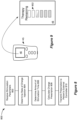
- Figure 9 illustrates an embodiment of an external controller 45 having a display 46.
- the external controller may comprise a stimulation tracking and display module 704 ( FIG. 7 ) configured to receive the stimulation prescription from the physician controller and to account for the amount of charge used during stimulation.
- the amount of charge remaining for the patient's prescription may be displayed on the display 46 of the patient's external controller.
- the external controller presents a gauge 902 indicating the amount of therapy remaining on the prescription.
- the patient uses their SCS system their external controller can track the amount of charge used and may display the amount of charge remaining on the prescription (either as charge or some variable related to charge).
- the patient's prescribed charge is depleted or approaching depletion, they may be prompted to schedule a follow-up appointment with the clinician.
- the patient may use their prescribed amount of stimulation at a faster rate than anticipated, for example, by applying stimulation more frequently or by using a greater amplitude or pulse width. In that case, the patient will be prompted to schedule a follow-up sooner than the anticipated six months. This may afford the patient and clinician to explore reasons that the patient is requiring more stimulation than anticipated.
- stimulation may be provided in discreet chunks of stimulation, referred to as a "bolus" of stimulation.
- a bolus of stimulation may be thought of as analogous to a single dose of stimulation, similar to a dose of a pharmaceutical agent.
- a bolus may comprise stimulation for a first period of time, such as 10 minutes of stimulation (or 30 minutes, or 1 hour, etc.). After a bolus is issued further stimulation is not provided until another bolus is issued.
- the time period between boluses i.e., a second period of time
- the second period of time may be thirty minutes to twelve hours.
- a patient could issue themselves another bolus immediately following a first bolus, just as patient could take a second dose of a pharmaceutical immediately following a first dose.
- a clinician may prescribe stimulation therapy based on a number of boluses of stimulation.
- a clinician might prescribe a given number of boluses of stimulation to a patient per day for a certain duration. For example, a clinician might prescribe five 30-minute boluses of stimulation per day for three months, after which the patient returns to the clinician for a follow-up evaluation.
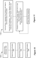
- FIGS. 4 , 5 , and 7 illustrate an example of a method 1000 of determining and prescribing a bolus mode treatment.
- appropriate stimulation parameters are determined for the patient. This process is generally done in a fitting session with the aid of a clinician programmer 50 ( FIGS. 4 , 5 , and 7 ), as described above. Assume that, during the fitting process, the clinician has determined one or more stimulation programs that alleviate the patient's pain and also assume that the clinician believes that the patient may respond well to bolus mode treatment. Having determined optimum stimulation parameters, the patient may be released with an implanted IPG (or ETS or EPS) and their external controller 45 to determine an appropriate time period corresponding to a bolus of stimulation.
- IPG implanted IPG
- EPS external controller 45
- the stimulation tracking and display module 704 in the patient's external controller may be programmed with a bolus algorithm configured to help the patient and clinician determine an appropriate bolus of stimulation.
- the goal is to determine a time period of stimulation that achieves long-lasting pain relief.
- they may activate a trial bolus.
- a trial bolus may comprise 5 minutes of stimulation using the patient's optimum stimulation parameters.
- the patient will receive a bolus of stimulation, after which the stimulation will terminate.
- the patient may then be asked to periodically rate their pain relief (for example, every hour after the administration of the trial bolus) using the interface of their external controller.
- time periods of stimulation may be tried to determine a minimum time period that provides the longest-lasting pain relief.
- Various optimization criteria may be used for making the determination of an optimum bolus, depending on the patient's and the clinician's preferences. Alternatively, the clinician may simply decide what time period of stimulation will constitute a bolus of stimulation at step 1004.
- the patient may receive a prescription for a number of boluses (step 1006).
- the patient may return to their clinician following the bolus determination step (step 1004) so that the clinician can program the patient's external controller with a prescription for a given number of boluses.
- the patient's external controller is an internet-connected device, the patient may not need to return to the clinician. Instead, the patient's external controller may transmit the bolus duration to the clinician programmer via an internet connection and the clinician programmer may transmit the bolus prescription to the patient's external controller via the internet connection.
- the external controller can monitor the number of boluses used (Step 1008).
- the number of boluses remaining on the patient's prescription may be displayed on the external controller.
- the patient may be prompted to schedule a follow-up visit with the clinician.
- the clinician may simply prescribe a certain stimulation duration as a bolus without using an algorithm such as the algorithm 1000. For example, the clinician may simply decide that a bolus of stimulation will correspond to ten minutes of stimulation.
- the patient's external controller may be programmed with an algorithm that helps the patient determine an appropriate bolus of stimulation without approval of the clinician.
- the patient's external controller may be programmed with a bolus calibration duration, for example, two weeks, during which the patient is prompted to rank therapy using different bolus durations. After the calibration duration, the external controller considers the determined optimum duration of stimulation as a bolus of stimulation.
- the external controller may then begin tracking the number of boluses remaining for the patient's prescription. For example, the GUI of the external controller may inform the patient that they have x of y boluses remaining.
- the patient's external controller may be programmed with one or more algorithms that attempt to optimize when a bolus of stimulation should issue.
- the algorithm determines that a bolus should be issued, the patient's external controller may alert the patient to administer themselves a bolus of stimulation.
- Such an embodiment may be particularly useful for patients using an RF system (i.e., a system without an implanted IPG).
- a patient using such a system can receive a notice or alert when it is time to receive a bolus of stimulation and the patient can then arrange their external power supply (EPS) appropriately an administer themselves a bolus.
- EPS external power supply
- a patient using a system with a traditional IPG can use their external controller to cause the IPG to issue a bolus of stimulation when they receive an alert that it is time to issue a bolus.
- the external controller may simply instruct the IPG to issue a bolus automatically without the patient instructing the external controller to so.
- the patient may receive an alert on their personal computing device, such as a personal phone, that it is time to take a bolus.
- Figure 11 illustrates an example of an algorithm 1100 for predicting when a bolus should issue.
- the algorithm 1100 comprises a "training period" during which the algorithm attempts to correlate one or more "pain predictors" with instances that the patient issues themselves a bolus.
- the pain predictor is a predictor indicative of a need for stimulation. Examples of pain predictors may include the time of day, the weather, the patient's activity level, or one or more physiological parameters of the patient, such as heartrate, blood pressure, posture, or the like.
- the algorithm may determine that the patient tends to issue themselves a bolus at certain times during the day. The algorithm may therefore determine that those are the times of day that the patient tends to experience pain.
- the algorithm may determine that the patient tends to administer a bolus when they transition from sitting to standing, or vice-versa.
- postural changes may be detected using measured evoked compound action potentials (ECAPs) or other sensed neural responses, as described in Provisional Patent Application No. 62/860,627, filed January 22, 2019 , Attorney Docket No. 585-0308PUS.
- ECAPs evoked compound action potentials
- postural changes and/or patient activity level may be determined using accelerometers.
- Physiological parameters such as heartrate, blood pressure, and the like may be determined using one or more physiological sensors associated with the patient.
- pain predictors such as activity level, weather, posture, and the like, may be determined based on patient input, for example, via an application running on their external controller or other external device in communication with their external controller.
- the patient's external controller or other external device in communication with the external controller
- the training period may be a few days or a few weeks, for example.
- the algorithm may proceed to a directed therapy or automatic therapy regime wherein the algorithm monitors for one or more of the pain predictors.
- the algorithm may either instruct the patient to preemptively issue themselves a bolus or may automatically issue the patient a bolus without patient input.
- embodiments wherein the patient is instructed to issue themselves a bolus are particularly useful for patients with an RF system that does not use an implanted IPG.
- the patient may be prompted for feedback ranking the effectiveness of the attempted therapy programs, for example, by selecting a ranking on the user interface of their external controller.
- the algorithm may attempt to optimize the algorithm.
- Figures 12A-12C illustrate an example of the algorithm 1100 for determining when to preemptively issue a bolus of stimulation.
- the example algorithm 1100 illustrated in Figures 12A-12C uses the time of day as the pain predictor and also uses patient feedback to optimize the algorithm.
- Figure 12A illustrates a training period where the patient self-administers a bolus (represented by a capsule in Figures 12A-12C ) each time they perceive the onset of pain (represented by a lighting bolt).
- an algorithm may track the times that the patient issues themselves a bolus and then attempt to preemptively issue a bolus before the patient experiences pain onset. Notice in Figure 12A that the patient's pain onset events are weighted more heavily to the early part of the day.
- Figure 12B illustrates an attempt by the algorithm to preemptively issue boluses of therapy over a three-day period based on the boluses that the patient administered in Figure 12A .
- the patient on average, administered three boluses per day.
- the algorithm 1100 automatically provides those boluses each day at time periods that best match those in Figure 12A .
- the patient can continue to self-administer boluses and the algorithm 1100 can continue to optimize the timing of automatically providing boluses.
- the preemptively issued boluses of were not sufficient to completely curtail the patient's pain and the patient had to self-administer an extra bolus on those days.
- the patient has rated the therapy two-out-of-five.
- the algorithm has attempted to improve the therapy by issuing the third bolus earlier in the day, corresponding to the self-administered boluses.
- the patient has not had to self-administer a bolus of stimulation over a three-day period and has ranked the therapy a four-out-of-five.
- the algorithm 1100 may thus determine that the timing determined in Figure 10C may be used as ongoing therapy.
- Bolus mode therapy may provide several advantages compared to traditional continuous therapy. For example, bolus mode therapy may decrease the chances that the patient overuses stimulation, thereby developing a tolerance to the therapy. Also, bolus mode therapy is particularly well suited for RF stimulation systems, such as described above with reference to Figure 6 . Since a bolus of stimulation is only applied for a finite duration of time, a patient using an RF system need only have access to their external power supply during the time they are receiving a bolus of stimulation.
- Various aspects of the disclosed techniques can be formulated and stored as instructions in a computer-readable media associated with such devices, such as in a magnetic, optical, or solid-state memory.
- the computer-readable media with such stored instructions may also comprise a device readable by the clinician programmer or external controller, such as in a memory stick or a removable disk, and may reside elsewhere.
- the computer-readable media may be associated with a server or any other computer device, thus allowing instructions to be downloaded to the clinician programmer system or external controller or to the IPG or ETS, via the Internet for example.
- the various algorithms described herein and stored in non-transitory computer readable media can be executed by one or more microprocessors and/or control circuitry configured within the relevant device, thereby causing the device to perform the steps of the algorithm(s).
- the applications to which this present disclosure claim priority are directed to concepts (e.g., picking optimal stimulation parameters, and in particular stimulation parameters that cause sub-perception at lower frequencies) that are relevant to what is disclosed.
- Techniques in the present disclosure can also be used in the context of these priority applications.
- the prescribed stimulation may be determined and optimized using the techniques described in some of the priority applications.
- the parameters of the bolus stimulation may be determined and optimized using the techniques described in some of the priority applications.
Landscapes
- Health & Medical Sciences (AREA)
- Engineering & Computer Science (AREA)
- Life Sciences & Earth Sciences (AREA)
- Animal Behavior & Ethology (AREA)
- Neurology (AREA)
- Biomedical Technology (AREA)
- Nuclear Medicine, Radiotherapy & Molecular Imaging (AREA)
- Radiology & Medical Imaging (AREA)
- Veterinary Medicine (AREA)
- Public Health (AREA)
- General Health & Medical Sciences (AREA)
- Neurosurgery (AREA)
- Pain & Pain Management (AREA)
- Human Computer Interaction (AREA)
- Orthopedic Medicine & Surgery (AREA)
- Electrotherapy Devices (AREA)
Applications Claiming Priority (9)
| Application Number | Priority Date | Filing Date | Title |
|---|---|---|---|
| US201962803330P | 2019-02-08 | 2019-02-08 | |
| US16/460,640 US12485273B2 (en) | 2017-08-11 | 2019-07-02 | Modelling relationships between stimulation parameters and use thereof for automatic customization of sub-perception therapy in a spinal cord stimulation system |
| US16/460,655 US11338127B2 (en) | 2017-08-11 | 2019-07-02 | Stimulation modes to adapt customized stimulation parameters for use in a spinal cord stimulation system |
| US201962916958P | 2019-10-18 | 2019-10-18 | |
| US16/657,560 US20200046980A1 (en) | 2017-08-11 | 2019-10-18 | Varying Stimulation Parameters to Prevent Tissue Habituation in a Spinal Cord Stimulation System |
| US16/738,786 US11951314B2 (en) | 2017-08-11 | 2020-01-09 | Fitting algorithm to determine best stimulation parameter from a patient model in a spinal cord stimulation system |
| EP23178615.3A EP4233996B1 (de) | 2019-02-08 | 2020-01-13 | System zur abgabe der verordneten neuromodulationsdosis |
| EP20705827.2A EP3890822B1 (de) | 2019-02-08 | 2020-01-13 | System zur abgabe der verordneten neuromodulationsdosis |
| PCT/US2020/013346 WO2020163046A1 (en) | 2019-02-08 | 2020-01-13 | System for delivering prescribed neuromodulation dose |
Related Parent Applications (3)
| Application Number | Title | Priority Date | Filing Date |
|---|---|---|---|
| EP20705827.2A Division EP3890822B1 (de) | 2019-02-08 | 2020-01-13 | System zur abgabe der verordneten neuromodulationsdosis |
| EP23178615.3A Division EP4233996B1 (de) | 2019-02-08 | 2020-01-13 | System zur abgabe der verordneten neuromodulationsdosis |
| EP23178615.3A Division-Into EP4233996B1 (de) | 2019-02-08 | 2020-01-13 | System zur abgabe der verordneten neuromodulationsdosis |
Publications (2)
| Publication Number | Publication Date |
|---|---|
| EP4512461A2 true EP4512461A2 (de) | 2025-02-26 |
| EP4512461A3 EP4512461A3 (de) | 2025-05-07 |
Family
ID=71948285
Family Applications (3)
| Application Number | Title | Priority Date | Filing Date |
|---|---|---|---|
| EP24210637.5A Pending EP4512461A3 (de) | 2019-02-08 | 2020-01-13 | System zur abgabe einer vorgeschriebenen neuromodulationsdosis |
| EP20705827.2A Active EP3890822B1 (de) | 2019-02-08 | 2020-01-13 | System zur abgabe der verordneten neuromodulationsdosis |
| EP23178615.3A Active EP4233996B1 (de) | 2019-02-08 | 2020-01-13 | System zur abgabe der verordneten neuromodulationsdosis |
Family Applications After (2)
| Application Number | Title | Priority Date | Filing Date |
|---|---|---|---|
| EP20705827.2A Active EP3890822B1 (de) | 2019-02-08 | 2020-01-13 | System zur abgabe der verordneten neuromodulationsdosis |
| EP23178615.3A Active EP4233996B1 (de) | 2019-02-08 | 2020-01-13 | System zur abgabe der verordneten neuromodulationsdosis |
Country Status (5)
| Country | Link |
|---|---|
| EP (3) | EP4512461A3 (de) |
| CN (1) | CN113382765B (de) |
| AU (2) | AU2020218477B2 (de) |
| CA (1) | CA3128167A1 (de) |
| WO (1) | WO2020163046A1 (de) |
Families Citing this family (1)
| Publication number | Priority date | Publication date | Assignee | Title |
|---|---|---|---|---|
| CN114733069A (zh) * | 2022-04-11 | 2022-07-12 | 苏州景昱医疗器械有限公司 | 程控装置、方法、电子设备及存储介质 |
Citations (9)
| Publication number | Priority date | Publication date | Assignee | Title |
|---|---|---|---|---|
| US6516227B1 (en) | 1999-07-27 | 2003-02-04 | Advanced Bionics Corporation | Rechargeable spinal cord stimulator system |
| US8606362B2 (en) | 2005-07-08 | 2013-12-10 | Boston Scientific Neuromodulation Corporation | Current output architecture for an implantable stimulator device |
| US8620436B2 (en) | 2005-07-08 | 2013-12-31 | Boston Scientific Neuromodulation Corporation | Current generation architecture for an implantable stimulator device having coarse and fine current control |
| US20150080982A1 (en) | 2013-09-13 | 2015-03-19 | Boston Scientific Neuromodulation Corporation | Window in a Case of an Implantable Medical Device to Facilitate Optical Communications With External Devices |
| US20150231402A1 (en) | 2014-02-14 | 2015-08-20 | Boston Scientific Neuromodulation Corporation | Plug-In Accessory for Configuring a Mobile Device into an External Controller for an Implantable Medical Device |
| US20150360038A1 (en) | 2014-06-13 | 2015-12-17 | Boston Scientific Neuromodulation Corporation | Heads-Up Display and Control of an Implantable Medical Device |
| US20160144183A1 (en) | 2014-11-21 | 2016-05-26 | Boston Scientific Neuromodulation Corporation | Implantable Stimulator Device Having Small DC-Blocking Capacitors |
| US20180071513A1 (en) | 2016-09-10 | 2018-03-15 | Boston Scientific Neuromodulation Corporation | Pulse Definition Circuitry for Creating Stimulation Waveforms in an Implantable Pulse Generator |
| US20180071520A1 (en) | 2016-09-10 | 2018-03-15 | Boston Scientific Neuromodulation Corporation | Current Generation Architecture for an Implantable Medical Device |
Family Cites Families (16)
| Publication number | Priority date | Publication date | Assignee | Title |
|---|---|---|---|---|
| BR8707351A (pt) * | 1986-06-16 | 1988-09-13 | Zion Educational Found | Aparelho e processo para emissao de forma de onda de sinal prescritivo,aparelho e processo aplicador de sinais eletricos,processo para emissao de forma de onda eletrica prescritiva e processo para emissao de sinal eletrico prescritivo |
| US6108579A (en) * | 1996-04-15 | 2000-08-22 | Pacesetter, Inc. | Battery monitoring apparatus and method for programmers of cardiac stimulating devices |
| US7359751B1 (en) * | 2004-05-05 | 2008-04-15 | Advanced Neuromodulation Systems, Inc. | Clinician programmer for use with trial stimulator |
| US7668598B2 (en) * | 2006-05-18 | 2010-02-23 | Uroplasty, Inc. | Method and apparatus for stimulating a nerve of a patient |
| US20130110195A1 (en) * | 2009-01-15 | 2013-05-02 | Autonomic Technologies, Inc. | Neurostimulator system, apparatus, and method |
| EP2243510B1 (de) * | 2009-04-22 | 2014-04-09 | Nevro Corporation | Systeme zur selektiven Hochfrequenzrückenmarksmodulation zur Vermeidung von Schmerzen mit weniger Nebenwirkungen |
| WO2012075497A1 (en) * | 2010-12-03 | 2012-06-07 | Spr Therapeutics, Llc | Systems and methods for treating shoulder pain related to subacromial impingement syndrome |
| JP2013542835A (ja) | 2010-11-17 | 2013-11-28 | ボストン サイエンティフィック ニューロモデュレイション コーポレイション | 埋め込み型神経刺激システム内で使用可能な外部試験刺激器 |
| US9314627B2 (en) * | 2011-04-25 | 2016-04-19 | Cardiac Pacemakers, Inc. | Systems and methods to account for neck movement during nerve stimulation |
| US10448889B2 (en) * | 2011-04-29 | 2019-10-22 | Medtronic, Inc. | Determining nerve location relative to electrodes |
| WO2014165695A1 (en) * | 2013-04-04 | 2014-10-09 | Boston Scientific Neuromodulation Corporation | Management of stimulation safety limits in a neurostimulation system |
| US9616222B2 (en) * | 2014-12-03 | 2017-04-11 | Neurohabilitation Corporation | Systems for providing non-invasive neurorehabilitation of a patient |
| US10076667B2 (en) * | 2015-06-09 | 2018-09-18 | Nuvectra Corporation | System and method of performing computer assisted stimulation programming (CASP) with a non-zero starting value customized to a patient |
| US10716937B2 (en) * | 2016-09-10 | 2020-07-21 | Boston Scientific Neuromodulation Corporation | Passive charge recovery circuitry for an implantable medical device |
| US10792491B2 (en) * | 2016-11-23 | 2020-10-06 | Boston Scientific Neuromodulation Corporation | Pulsed passive charge recovery circuitry for an implantable medical device |
| US10675469B2 (en) * | 2017-01-11 | 2020-06-09 | Boston Scientific Neuromodulation Corporation | Pain management based on brain activity monitoring |
-
2020
- 2020-01-13 AU AU2020218477A patent/AU2020218477B2/en active Active
- 2020-01-13 EP EP24210637.5A patent/EP4512461A3/de active Pending
- 2020-01-13 CA CA3128167A patent/CA3128167A1/en active Pending
- 2020-01-13 CN CN202080011944.2A patent/CN113382765B/zh active Active
- 2020-01-13 WO PCT/US2020/013346 patent/WO2020163046A1/en not_active Ceased
- 2020-01-13 EP EP20705827.2A patent/EP3890822B1/de active Active
- 2020-01-13 EP EP23178615.3A patent/EP4233996B1/de active Active
-
2023
- 2023-02-28 AU AU2023201208A patent/AU2023201208B2/en active Active
Patent Citations (9)
| Publication number | Priority date | Publication date | Assignee | Title |
|---|---|---|---|---|
| US6516227B1 (en) | 1999-07-27 | 2003-02-04 | Advanced Bionics Corporation | Rechargeable spinal cord stimulator system |
| US8606362B2 (en) | 2005-07-08 | 2013-12-10 | Boston Scientific Neuromodulation Corporation | Current output architecture for an implantable stimulator device |
| US8620436B2 (en) | 2005-07-08 | 2013-12-31 | Boston Scientific Neuromodulation Corporation | Current generation architecture for an implantable stimulator device having coarse and fine current control |
| US20150080982A1 (en) | 2013-09-13 | 2015-03-19 | Boston Scientific Neuromodulation Corporation | Window in a Case of an Implantable Medical Device to Facilitate Optical Communications With External Devices |
| US20150231402A1 (en) | 2014-02-14 | 2015-08-20 | Boston Scientific Neuromodulation Corporation | Plug-In Accessory for Configuring a Mobile Device into an External Controller for an Implantable Medical Device |
| US20150360038A1 (en) | 2014-06-13 | 2015-12-17 | Boston Scientific Neuromodulation Corporation | Heads-Up Display and Control of an Implantable Medical Device |
| US20160144183A1 (en) | 2014-11-21 | 2016-05-26 | Boston Scientific Neuromodulation Corporation | Implantable Stimulator Device Having Small DC-Blocking Capacitors |
| US20180071513A1 (en) | 2016-09-10 | 2018-03-15 | Boston Scientific Neuromodulation Corporation | Pulse Definition Circuitry for Creating Stimulation Waveforms in an Implantable Pulse Generator |
| US20180071520A1 (en) | 2016-09-10 | 2018-03-15 | Boston Scientific Neuromodulation Corporation | Current Generation Architecture for an Implantable Medical Device |
Also Published As
| Publication number | Publication date |
|---|---|
| EP4512461A3 (de) | 2025-05-07 |
| EP4233996A2 (de) | 2023-08-30 |
| AU2023201208A1 (en) | 2023-04-06 |
| AU2020218477B2 (en) | 2022-12-01 |
| EP3890822A1 (de) | 2021-10-13 |
| CN113382765B (zh) | 2023-12-08 |
| EP3890822B1 (de) | 2023-07-26 |
| EP4233996A3 (de) | 2023-11-08 |
| CA3128167A1 (en) | 2020-08-13 |
| AU2020218477A1 (en) | 2021-07-29 |
| EP4233996B1 (de) | 2025-02-26 |
| CN113382765A (zh) | 2021-09-10 |
| AU2023201208B2 (en) | 2024-06-06 |
| WO2020163046A1 (en) | 2020-08-13 |
Similar Documents
| Publication | Publication Date | Title |
|---|---|---|
| US11338141B2 (en) | Paresthesia-free spinal cord stimulation occurring at lower frequencies and sweet spot searching using paresthesia | |
| US12427324B2 (en) | Prescribed neuromodulation dose delivery | |
| US20240226561A1 (en) | Tools To Assist Spinal Cord Stimulation Self-Reprogramming | |
| US12042656B2 (en) | Bolus stimulation in a neurostimulation device particularly useful in providing sub-perception stimulation | |
| US20120290039A1 (en) | Management of stimulation safety limits in a neurostimulation system | |
| EP4017577B1 (de) | Neurostimulationsvorrichtung mit sub-wahrnehmungsstimulation | |
| US20220379127A1 (en) | Forecasting Stimulation Adjustments in a Stimulator System Using Time Series Analysis | |
| AU2023201208B2 (en) | System for delivering prescribed neuromodulation dose | |
| US20220401740A1 (en) | Ramping of Neural Dosing for Comprehensive Spinal Cord Stimulation Therapy | |
| EP4252834B1 (de) | Werkzeuge zur unterstützung der selbstumprogrammierung der rückenmarksstimulation | |
| US20240342480A1 (en) | Bolus Stimulation in a Neurostimulation Device Particularly Useful in Providing Sub-Perception Stimulation | |
| CA3157918C (en) | Neurostimulation device providing sub-perception stimulation | |
| CA3128166C (en) | Tools to assist spinal cord stimulation self-reprogramming |
Legal Events
| Date | Code | Title | Description |
|---|---|---|---|
| PUAI | Public reference made under article 153(3) epc to a published international application that has entered the european phase |
Free format text: ORIGINAL CODE: 0009012 |
|
| STAA | Information on the status of an ep patent application or granted ep patent |
Free format text: STATUS: REQUEST FOR EXAMINATION WAS MADE |
|
| 17P | Request for examination filed |
Effective date: 20241204 |
|
| AC | Divisional application: reference to earlier application |
Ref document number: 3890822 Country of ref document: EP Kind code of ref document: P Ref document number: 4233996 Country of ref document: EP Kind code of ref document: P |
|
| AK | Designated contracting states |
Kind code of ref document: A2 Designated state(s): AL AT BE BG CH CY CZ DE DK EE ES FI FR GB GR HR HU IE IS IT LI LT LU LV MC MK MT NL NO PL PT RO RS SE SI SK SM TR |
|
| REG | Reference to a national code |
Ref country code: DE Ref legal event code: R079 Free format text: PREVIOUS MAIN CLASS: A61N0001020000 Ipc: A61N0001050000 |
|
| PUAL | Search report despatched |
Free format text: ORIGINAL CODE: 0009013 |
|
| AK | Designated contracting states |
Kind code of ref document: A3 Designated state(s): AL AT BE BG CH CY CZ DE DK EE ES FI FR GB GR HR HU IE IS IT LI LT LU LV MC MK MT NL NO PL PT RO RS SE SI SK SM TR |
|
| RIC1 | Information provided on ipc code assigned before grant |
Ipc: A61N 1/02 20060101ALI20250401BHEP Ipc: A61N 1/372 20060101ALI20250401BHEP Ipc: A61N 1/36 20060101ALI20250401BHEP Ipc: A61N 1/05 20060101AFI20250401BHEP |
|
| RIC1 | Information provided on ipc code assigned before grant |
Ipc: A61N 1/05 20060101AFI20251201BHEP Ipc: A61N 1/36 20060101ALI20251201BHEP Ipc: A61N 1/372 20060101ALI20251201BHEP Ipc: A61N 1/02 20060101ALI20251201BHEP |
|
| GRAP | Despatch of communication of intention to grant a patent |
Free format text: ORIGINAL CODE: EPIDOSNIGR1 |
|
| STAA | Information on the status of an ep patent application or granted ep patent |
Free format text: STATUS: GRANT OF PATENT IS INTENDED |
|
| INTG | Intention to grant announced |
Effective date: 20260122 |
|
| GRAJ | Information related to disapproval of communication of intention to grant by the applicant or resumption of examination proceedings by the epo deleted |
Free format text: ORIGINAL CODE: EPIDOSDIGR1 |
|
| STAA | Information on the status of an ep patent application or granted ep patent |
Free format text: STATUS: REQUEST FOR EXAMINATION WAS MADE |
|
| INTC | Intention to grant announced (deleted) | ||
| GRAP | Despatch of communication of intention to grant a patent |
Free format text: ORIGINAL CODE: EPIDOSNIGR1 |
|
| STAA | Information on the status of an ep patent application or granted ep patent |
Free format text: STATUS: GRANT OF PATENT IS INTENDED |