EP4512265A2 - Rauchersatzsystem - Google Patents
Rauchersatzsystem Download PDFInfo
- Publication number
- EP4512265A2 EP4512265A2 EP25151008.7A EP25151008A EP4512265A2 EP 4512265 A2 EP4512265 A2 EP 4512265A2 EP 25151008 A EP25151008 A EP 25151008A EP 4512265 A2 EP4512265 A2 EP 4512265A2
- Authority
- EP
- European Patent Office
- Prior art keywords
- aerosol
- puff
- smoking substitute
- heating element
- consumable
- Prior art date
- Legal status (The legal status is an assumption and is not a legal conclusion. Google has not performed a legal analysis and makes no representation as to the accuracy of the status listed.)
- Pending
Links
Images


Classifications
-
- A—HUMAN NECESSITIES
- A24—TOBACCO; CIGARS; CIGARETTES; SIMULATED SMOKING DEVICES; SMOKERS' REQUISITES
- A24F—SMOKERS' REQUISITES; MATCH BOXES; SIMULATED SMOKING DEVICES
- A24F40/00—Electrically operated smoking devices; Component parts thereof; Manufacture thereof; Maintenance or testing thereof; Charging means specially adapted therefor
- A24F40/50—Control or monitoring
- A24F40/57—Temperature control
Definitions
- the present invention relates to a smoking substitute device and particularly, although not exclusively, to a smoking substitute device.
- the smoking of tobacco is generally considered to expose a smoker to potentially harmful substances. It is generally thought that a significant amount of the potentially harmful substances are generated through the heat caused by the burning and/or combustion of the tobacco and the constituents of the burnt tobacco in the tobacco smoke itself.
- Conventional combustible smoking articles such as cigarettes, typically comprise a cylindrical rod of tobacco comprising shreds of tobacco which is surrounded by a wrapper, and usually also a cylindrical filter axially aligned in an abutting relationship with the wrapped tobacco rod.
- the filter typically comprises a filtration material which is circumscribed by a plug wrap.
- the wrapped tobacco rod and the filter are joined together by a wrapped band of tipping paper that circumscribes the entire length of the filter and an adjacent portion of the wrapped tobacco rod.
- a conventional cigarette of this type is used by lighting the end opposite to the filter, and burning the tobacco rod. The smoker receives mainstream smoke into their mouth by drawing on the mouth end or filter end of the cigarette.
- Such smoking substitute systems can form part of nicotine replacement therapies aimed at people who wish to stop smoking and overcome a dependence on nicotine.
- Smoking substitute systems include electronic systems that permit a user to simulate the act of smoking by producing an aerosol (also referred to as a "vapour") that is drawn into the lungs through the mouth (inhaled) and then exhaled.
- aerosol also referred to as a "vapour”
- the inhaled aerosol typically bears nicotine and/or flavourings without, or with fewer of, the odour and health risks associated with traditional smoking.
- smoking substitute systems are intended to provide a substitute for the rituals of smoking, whilst providing the user with a similar experience and satisfaction to those experienced with traditional smoking and with combustible tobacco products.
- Some smoking substitute systems use smoking substitute articles (also referred to as a "consumables”) that are designed to resemble a traditional cigarette and are cylindrical in form with a mouthpiece at one end.
- HT Heated Tobacco
- HNB Heat not burn
- the tobacco may be leaf tobacco or reconstituted tobacco.
- the vapour may contain nicotine and/or flavourings.
- the intention is that the tobacco is heated but not burned, i.e. the tobacco does not undergo combustion.
- a typical HT smoking substitute system may include a device and a consumable.
- the consumable may include the tobacco material.
- the device and consumable may be configured to be physically coupled together.
- heat may be imparted to the tobacco material by a heating element of the device, wherein airflow through the tobacco material causes components in the tobacco material to be released as vapour.
- a vapour may also be formed from a carrier in the tobacco material (this carrier may for example include propylene glycol and/or vegetable glycerine) and additionally volatile compounds released from the tobacco.
- the released vapour may be entrained in the airflow drawn through the tobacco.
- the vapour passes through the consumable (entrained in the airflow) from the location of vaporisation to an outlet of the consumable (e.g. a mouthpiece), the vapour cools and condenses to form an aerosol for inhalation by the user.
- the aerosol will normally contain the volatile compounds.
- HT smoking substitute systems heating as opposed to burning the tobacco material is believed to cause fewer, or smaller quantities, of the more harmful compounds ordinarily produced during smoking. Consequently, the HT approach may reduce the odour and/or health risks that can arise through the burning, combustion and pyrolytic degradation of tobacco.
- the present invention relates to smoking substitute device to change operation by determining puff duration.
- a smoking substitute device comprising: a puff measurement means configured to measure a puff duration associated with a user puff action; and a controller configured to change an operating temperature of a heating element of the smoking substitute device, based on the measured puff duration.
- a smoking substitute device comprising a controller configured to change operating temperature of a heating element based on puff duration associated with a user puff action
- the device provides adaptive heating of the heating element to counteract the effect of the user puff on temperature. This may provide an improved user experience.
- the change of operating temperature includes an increase in operating temperature.
- the change of temperature occurs during the user puff action.
- the change of temperature occurs during a subsequent user puff action.
- the controller changes the operating temperature when the measured puff duration is greater than a predefined threshold duration.
- the controller increases the operating temperature to a predefined elevated temperature.
- the controller increases the operating temperature until the user puff action ends.
- the puff measurement means includes a puff sensor.
- the substitute smoking device is a heat not burn device.
- a method of operating a smoking substitute device comprising: measuring a puff duration associated with a user puff action of the smoking substitute device; and changing an operating temperature of a heating element of the smoking substitute device, based on the measured puff duration.
- the operating temperature is increased when the puff duration is greater than a predefined threshold value.
- the operating temperature is increased to a predefined elevated temperature.
- the operating temperature is increased until the user puff action ends.
- the operating temperature is gradually increases until the user puff action ends.
- a substitute smoking system comprising: a device according to the first aspect or a device operated according to the second aspect; and an aerosol-forming article.
- a method of a system according the third aspect comprising: inserting the aerosol-forming article into the device; and operating the device to heat the aerosol-forming article using a heating element of the device.
- the device may comprise an elongate body.
- An end of the elongate body may be configured for engagement with an aerosol-forming article.
- the body may be configured for engagement with a heated tobacco (HT) consumable (or heat-not-burn (HNB) consumable) or an e-cigarette consumable.
- HT heated tobacco
- HNB heat-not-burn
- the terms "heated tobacco” and “heat-not-burn” are used interchangeably herein to describe a consumable that is of the type that is heated rather than combusted (or are used interchangeably to describe a device for use with such a consumable).
- the device may comprise a cavity that is configured for receipt of at least a portion of the consumable (i.e. for engagement with the consumable).
- the aerosol-forming article may be of the type that comprises an aerosol former (e.g. carried by an aerosol-forming substrate).
- the device may comprise a heater for heating the aerosol-forming article.
- the heater may comprise a heating element, which may be in the form of a rod that extends from the body of the device.
- the heating element may extend from the end of the body that is configured for engagement with the aerosol-forming article.
- the heater (and thus the heating element) may be rigidly mounted to the body.
- the heating element may be elongate so as to define a longitudinal axis and may, for example, have a transverse profile (i.e. transverse to a longitudinal axis of the heating element) that is substantially circular (i.e. the heating element may be generally cylindrical).
- the heating element may have a transverse profile that is rectangular (i.e. the heater may be a "blade heater”).
- the heating element may alternatively be in the shape of a tube (i.e. the heater may be a "tube heater”).
- the heating element may take other forms (e.g. the heating element may have an elliptical transverse profile).
- the shape and/or size (e.g. diameter) of the transverse profile of the heating element may be generally consistent for the entire length (or substantially the entire length) of the heating element.
- the heating element may be between 15 mm and 25 mm long, e.g. between 18 mm and 20 mm long, e.g. around 19 mm long.
- the heating element may have a diameter of between 1.5 mm and 2.5 mm, e.g. a diameter between 2 mm and 2.3 mm, e.g. a diameter of around 2.15 mm.
- the heating element may be formed of ceramic.
- the heating element may comprise a core (e.g. a ceramic core) comprising Al2O3.
- the core of the heating element may have a diameter of 1.8 mm to 2.1 mm, e.g. between 1.9 mm and 2 mm.
- the heating element may comprise an outer layer (e.g. an outer ceramic layer) comprising Al2O3.
- the thickness of the outer layer may be between 160 ⁇ m and 220 ⁇ m, e.g. between 170 ⁇ m and 190 ⁇ m, e.g. around 180 ⁇ m.
- the heating element may comprise a heating track, which may extend longitudinally along the heating element.
- the heating track may be sandwiched between the outer layer and the core of the heating element.
- the heating track may comprise tungsten and/or rhenium.
- the heating track may have a thickness of around 20 ⁇ m.
- the heating element may be located in the cavity (of the device), and may extend (e.g. along a longitudinal axis) from an internal base of the cavity towards an opening of the cavity.
- the length of the heating element i.e. along the longitudinal axis of the heater
- the heating element may be less than the depth of the cavity.
- the heating element may extend for only a portion of the length of the cavity. That is, the heating element may not extend through (or beyond) the opening of the cavity.
- the heating element may be configured for insertion into an aerosol-forming article (e.g. a HT consumable) when an aerosol-forming article is received in the cavity.
- a distal end (i.e. distal from a base of the heating element where it is mounted to the device) of the heating element may comprise a tapered portion, which may facilitate insertion of the heating element into the aerosol-forming article.
- the heating element may fully penetrate an aerosol-forming article when the aerosol-forming article is received in the cavity. That is, the entire length, or substantially the entire length, of the heating element may be received in the aerosol-forming article.
- the heating element may have a length that is less than, or substantially the same as, an axial length of an aerosol-forming substrate forming part of an aerosol-forming article (e.g. a HT consumable).
- an aerosol-forming substrate forming part of an aerosol-forming article (e.g. a HT consumable).
- the heating element may only penetrate the aerosol-forming substrate, rather than other components of the aerosol-forming article.
- the heating element may penetrate the aerosol-forming substrate for substantially the entire axial length of the aerosol forming-substrate of the aerosol-forming article.
- heat may be transferred from (e.g. an outer circumferential surface of) the heating element to the surrounding aerosol-forming substrate, when penetrated by the heating element. That is, heat may be transferred radially outwardly (in the case of a cylindrical heating element) or e.g. radially inwardly (in the case of a tube heater).
- the heating element of the tube heater may surround at least a portion of the cavity.
- the heating element may surround a portion of the aerosol-forming article (i.e. so as to heat that portion of the aerosol-forming article).
- the heating element may surround an aerosol forming substrate of the aerosol-forming article. That is, when an aerosol-forming article is engaged with the device, the aerosol forming substrate of the aerosol-forming article may be located adjacent an inner surface of the (tubular) heating element. When the heating element is activated, heat may be transferred radially inwardly from the inner surface of the heating element to heat the aerosol forming substrate.
- the cavity may comprise a (e.g. circumferential) wall (or walls) and the (tubular) heating element may extend around at least a portion of the wall(s).
- the wall may be located between the inner surface of the heating element and an outer surface of the aerosol-forming article.
- the wall (or walls) of the cavity may be formed from a thermally conductive material (e.g. a metal) to allow heat conduction from the heating element to the aerosol-forming article.
- heat may be conducted from the heating element, through the cavity wall (or walls), to the aerosol-forming substrate of an aerosol-forming article received in the cavity.
- the heater may form part of an aerosol-forming article for use with the device.
- the device may not comprise a heater.
- the aerosol-forming article may comprise a heater.
- Such arrangements may, for example, be suited to e-cigarette systems in which the aerosol-forming article comprises a tank containing an aerosol former (e.g. in liquid form).
- the device may comprise means for connecting the device the heater of an aerosol-forming article engaged with the device.
- the device may comprise one or more device connectors for (e.g. electrically) connecting the device to a corresponding heater connector of the aerosol-forming article.
- the connectors i.e. of both the device and the aerosol-forming article
- the connectors may be in the form of electrically conductive elements (e.g. plates) that contact when the aerosol-forming article is engaged with the device.
- the cap may be configured such that when an aerosol-forming article is engaged with the device (e.g. received in the cavity), only a portion of the aerosol-forming article is received in the cavity. That is, a portion of the aerosol-forming article (not received in the cavity) may protrude from (i.e. extend beyond) the opening.
- This (protruding) portion of the aerosol-forming article may be a terminal (e.g. mouth) end of the aerosol-forming article, which may be received in a user's mouth for the purpose of inhaling aerosol formed by the device.
- the device may comprise a power source or may be connectable to a power source (e.g. a power source separate to the device).
- the power source may be electrically connectable to the heater. In that respect, altering (e.g. toggling) the electrical connection of the power source to the heater may affect a state of the heater. For example, toggling the electrical connection of the power source to the heater may toggle the heater between an on state and an off state.
- the power source may be a power store.
- the power source may be a battery or rechargeable battery (e.g. a lithium ion battery).
- the UI may additionally or alternatively comprise output means to convey information to the user.
- the output means may comprise a light to indicate a condition of the device (and/or the aerosol-forming article) to the user.
- the condition of the device (and/or aerosol-forming article) indicated to the user may comprise a condition indicative of the operation of the heater.
- the condition may comprise whether the heater is in an off state or an on state.
- the UI unit may comprise at least one of a button, a display, a touchscreen, a switch, a light, and the like.
- the output means may comprise one or more (e.g. two, three, four, etc.) light-emitting diodes ("LEDs") that may be located on the body of the device.
- LEDs light-emitting diodes
- the device may further comprise a puff sensor (e.g. airflow sensor), which form part of the input means of the Ul.
- the puff sensor may be configured to detect a user drawing on an end (i.e. a terminal (mouth) end) of the aerosol-forming article.
- the puff sensor may, for example, be a pressure sensor or a microphone.
- the puff sensor may be configured to produce a signal indicative of a puff state.
- the signal may be indicative of the user drawing (an aerosol from the aerosol-forming article) such that it is e.g. in the form of a binary signal.
- the puff sensor may be configured to measure puff duration of a user puff action.
- the signal may be indicative of such puff duration.
- the signal may be indicative of a characteristic of the draw (e.g. a flow rate of the draw, length of time of the draw, etc).
- the device may comprise a controller, or may be connectable to a controller that may be configured to control at least one function of the device.
- the controller may comprise a microcontroller that may e.g. be mounted on a printed circuit board (PCB).
- the controller may also comprise a memory, e.g. nonvolatile memory.
- the memory may include instructions, which, when implemented, may cause the controller to perform certain tasks or steps of a method. Where the device comprises an input connection, the controller may be connected to the input connection.
- the controller may be operatively connected to one or more components of the Ul.
- the controller may be configured to receive command signals from an input means of the Ul.
- the controller may be configured to control the heater in response to the command signals.
- the controller may be configured to receive "on" and “off” command signals from the UI and, in response, may control the heater so as to be in a corresponding on or off state.
- the device may comprise a wireless interface configured to communicate wirelessly (e.g. via Bluetooth (e.g. a Bluetooth low-energy connection) or WiFi) with an external device.
- the input connection may be configured for wired connection to an external device so as to provide communication between the device and the external device.
- the aerosol-forming substrate may comprise plant material.
- the plant material may comprise least one plant material selected from the list including Amaranthus dubius, Arctostaphylos uva-ursi (Bearberry), Argemone mexicana, Amica, Artemisia vulgaris, Yellow Tees, Galea zacatechichi, Canavalia maritima (Baybean), Cecropia mexicana (Guamura), Cestrum noctumum, Cynoglossum virginianum (wild comfrey), Cytisus scoparius , Damiana, Entada rheedii, Eschscholzia califomica (California Poppy), Fittonia albivenis, Hippobroma longiflora, Humulus japonica (Japanese Hops), Humulus lupulus (Hops), Lactuca virosa (Lettuce Opium), Laggera alata, Leonot
- the plant material may be tobacco. Any type of tobacco may be used. This includes, but is not limited to, flue-cured tobacco, burley tobacco, Maryland Tobacco, dark-air cured tobacco, oriental tobacco, dark-fired tobacco, perique tobacco and rustica tobacco. This also includes blends of the above mentioned tobaccos.
- the aerosol-forming substrate may comprise a gathered sheet of homogenised (e.g. paper/slurry recon) tobacco or gathered shreds/strips formed from such a sheet.
- homogenised e.g. paper/slurry recon
- the aerosol-forming substrate may comprise one or more additives selected from humectants, flavourants, fillers, aqueous/non-aqueous solvents and binders.
- the flavourant may be provided in solid or liquid form. It may include menthol, liquorice, chocolate, fruit flavour (including e.g. citrus, cherry etc.), vanilla, spice (e.g. ginger, cinnamon) and tobacco flavour.
- the flavourant may be evenly dispersed throughout the aerosol-forming substrate or may be provided in isolated locations and/or varying concentrations throughout the aerosol-forming substrate.
- the aerosol-forming substrate may be formed in a substantially cylindrical shape such that the article/consumable resembles a conventional cigarette. It may have a diameter of between 5 and 10mm e.g. between 6 and 9mm or 6 and 8mm e.g. around 7 mm. It may have an axial length of between 10 and 15mm e.g. between 11 and 14mm such as around 12 or 13mm.
- the article/consumable may comprise at least one filter element. There may be a terminal filter element at the downstream/mouth end of the article/consumable.
- the terminal filter element (at the downstream end of the article/consumable) may be joined to the upstream elements forming the article/consumable by a circumscribing tipping layer e.g. a tipping paper layer.
- the tipping paper may have an axial length longer than the axial length of the terminal filter element such that the tipping paper completely circumscribes the terminal filter element plus the wrapping layer surrounding any adjacent upstream element.
- the article/consumable may comprise an aerosol-cooling element which is adapted to cool the aerosol generated from the aerosol-forming substrate (by heat exchange) before being inhaled by the user.
- the article/consumable may comprise a spacer element that defines a space or cavity between the aerosol-forming substrate and the downstream end of the consumable.
- the spacer element may comprise a cardboard tube.
- the spacer element may be circumscribed by the (paper) wrapping layer.
- the system may be in the form of an e-cigarette system (i.e. rather than a heated tobacco system as described above).
- the consumable may be in the form of an e-cigarette consumable.
- the e-cigarette system may be configured such that the consumable can be received and retained in the cavity of the device (i.e. so as to be engaged with the device).
- the consumable may be retained by way of e.g. an interference fit, screwing one onto (or onto) the other, a bayonet fitting, or by way of a snap engagement mechanism.
- the consumable may comprise a tank, which may define a reservoir for the storage of an aerosol former.
- the aerosol former may be in the form of an e-liquid (stored in the reservoir).
- the consumable may be a "single-use" consumable. That is, upon exhausting the e-liquid in the tank, the intention may be that the user disposes of the entire consumable.
- the e-liquid may be the only part of the system that is truly "single-use".
- the tank may be refillable with e-liquid or another component of the system (internal to the device or external to the device e.g. a refillable cartomizer) may define a reservoir for the e-liquid.
- the consumable may comprise a heater (i.e. instead of the heater forming part of the device) configured to heat and vaporise the e-liquid.
- the consumable may comprise a porous wick that conveys e-liquid from the tank to a heating element of the heater.
- the heating element may be a heating filament that is wound (e.g. helically) around at least a portion of the porous wick, such that when the heating element is heated (e.g. by the action of electrical current passing through the heating element), heat may be transferred from the heating element to the e-liquid conveyed by the wick. This transfer of heat may vaporise the e-liquid and the resultant vapour may be entrained in an airflow passing through the consumable.
- the consumable may further comprise one or more heater connectors for connecting the heater (of the consumable) to the device.
- the heater connectors may be in the form of electrically conductive element or contacts (e.g. metal plates) and may be disposed on an in-use device-facing surface of the consumable.
- the heater connectors may be electrically connected to the heater of the consumable, such that electricity supplied via the heater connectors may pass to the heater.
- a voltage applied across the heater connectors may generally correspond to a voltage applied across the heating element of the heater.
- the heater connectors may be arranged such that they contact corresponding device connectors of the device when the consumable is engaged with the device.
- the device connectors may be connected (e.g. electrically) to a power source (e.g. battery) of the device.
- a power source e.g. battery
- electricity may be supplied from the power source to the heating element, via in-contact heater and device connectors.
- the heater forming part of the consumable may operate (and interact with e.g. a controller) as otherwise described above with respect to a heater forming part of the device.
- a method of using the system according to the third aspect comprising inserting the aerosol-forming article into the device; and heating the article using the heater of the device.
- the method may comprise inserting the article into a cavity within a body of the device and penetrating the article with the heating element of the device upon insertion of the article.
- the invention includes the combination of the aspects and preferred features described except where such a combination is clearly impermissible or expressly avoided.
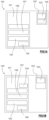
- FIG 1A is a schematic providing a general overview of a smoking substitute system 100.
- the system 100 includes a substitute smoking device 101 and an aerosol-forming article in the form of a consumable 102, which comprises an aerosol former 103.
- the system is configured to vaporise the aerosol former by heating the aerosol former 103 (so as to form a vapour/aerosol for inhalation by a user).
- the heater 104 forms part of the consumable 102 and is configured to heat the aerosol former 103. Heat from the heater 104 vaporises the aerosol former 103 to produce a vapour. The vapour subsequently condenses to form an aerosol, which is ultimately inhaled by the user.
- the system 100 further comprises a power source 105 that forms part of the device 101.
- the power source 105 may be external to (but connectable to) the device 101.
- the power source 105 is electrically connectable to the heater 104 such that it is able to supply power to the heater 104 (i.e. for the purpose of heating the aerosol former 103).
- control of the electrical connection of the power source 105 to the heater 104 provides control of the state of the heater 104.
- the power source 105 may be a power store, for example a battery or rechargeable battery (e.g. a lithium ion battery).
- the system 100 further comprises an I/O module comprising a connector 106 (e.g. in the form of a USB port, Micro USB port, USB-C port, etc.).
- the connector 106 is configured for connection to an external source of electrical power, e.g. a mains electrical supply outlet.
- the connector 106 may be used in substitution for the power source 105. That is the connector 106 may be electrically connectable to the heater 104 so as to supply electricity to the heater 104.
- the device may not include a power source, and the power source of the system may instead comprise the connector 106 and an external source of electrical power (to which the connector 106 provides electrical connection).
- the connector 106 may be used to charge and recharge the power source 105 where the power source 104 includes a rechargeable battery.
- the system 100 also comprises a user interface (Ul) 107.
- the UI 107 may include input means to receive commands from a user.
- the input means of the UI 107 allows the user to control at least one aspect of the operation of the system 100.
- the input means may, for example, be in the form of a button, touchscreen, switch, microphone, etc.
- the Ul 107 also comprises output means to convey information to the user.
- the output means may, for example, comprise lights (e.g. LEDs), a display screen, speaker, vibration generator, etc.
- the system 100 further comprises a controller 108 that is configured to control at least one function of the device 101.
- the controller 108 is a component of the device 101, but in other embodiments may be separate from (but connectable to) the device 101.
- the controller 108 is configured to control the operation of the heater 104 and, for example, may be configured to control the voltage applied from the power source 105 to the heater 104.
- the controller 108 may be configured to toggle the supply of power to the heater 105 between an on state, in which the full output voltage of the power source 105 is applied to the heater 104, and an off state, in which the no voltage is applied to the heater 104.
- the system 100 may also comprise a voltage regulator to regulate the output voltage from the power source 105 to form a regulated voltage.
- the regulated voltage may then be applied to the heater 104.
- the controller 108 is operatively connected to the UI 107.
- the controller 108 may receive an input signal from the input means of the UI 107.
- the controller 108 may transmit output signals to the UI 107.
- the output means of the UI 107 may convey information, based on the output signals, to a user.
- Figure 1B is a schematic showing a variation of the system 100 of Figure 1A .
- the heater 104 forms part of the consumable 102, rather than the device 101.
- the heater 104 is electrically connectable to the power source 105, for example, when the consumable 102 is engaged with the device 101.
- the systems 100, 100' of Figures 1A and 1B may be implemented as one of two broad categories of system, each in accordance with the present invention: a heated tobacco (HT) system or an e-cigarette system.
- HT heated tobacco
- e-cigarette e-cigarette
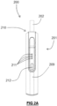
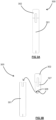
- Figures 2A and 2B illustrate a heated-tobacco (HT) smoking substitute system 200.
- the system 200 is an example of the systems 100, 100' described in relation to Figures 1A or 1B .
- System 200 includes an HT device 201 and an HT consumable 202.
- the description of Figures 1A and 1B above is applicable to the system 200 of Figures 2A and 2B , and will thus not be repeated.
- the device 201 and the consumable 202 are configured such that the consumable 202 can be engaged with the device 201.
- Figure 2A shows the device 201 and the consumable 202 in an engaged state
- Figure 2B shows the device 201 and the consumable 202 in a disengaged state.
- the device 201 comprises a body 209 and cap 210.
- the cap 209 is engaged at an end of the body 209.
- the cap 210 is moveable relative to the body 209.
- the cap 210 is slideable and can slide along a longitudinal axis of the body 209.
- the device 201 comprises an output means (forming part of the UI of the device 201) in the form of a plurality of light-emitting diodes (LEDs) 211 arranged linearly along the longitudinal axis of the device 201 and on an outer surface of the body 209 of the device 201.
- a button 212 is also arranged on an outer surface of the body 209 of the device 201 and is axially spaced (i.e. along the longitudinal axis) from the plurality of LEDs 211.
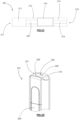
- FIG. 2C shows a detailed section view of the consumable of 202 of the system 200.
- the consumable 202 generally resembles a cigarette.
- the consumable 202 has a generally cylindrical form with a diameter of 7 mm and an axial length of 70 mm.
- the consumable 202 comprises an aerosol forming substrate 213, a terminal filter element 214, an upstream filter element 215 and a spacer element 216.
- the consumable may further comprise a cooling element.
- a cooling element may exchange heat with vapour that is formed by the aerosol-forming substrate 213 in order to cool the vapour so as to facilitate condensation of the vapour.
- the aerosol-forming substrate 213 is substantially cylindrical and is located at an upstream end 217 of the consumable 202, and comprises the aerosol former of the system 200.
- the aerosol forming substrate 213 is configured to be heated by the device 201 to release a vapour.
- the released vapour is subsequently entrained in an airflow flowing through the aerosol-forming substrate 213.
- the airflow is produced by the action of the user drawing on a downstream 218 (i.e. terminal or mouth end) of the consumable 202.
- the aerosol forming substrate 213 comprises tobacco material that may, for example, include any suitable parts of the tobacco plant (e.g. leaves, stems, roots, bark, seeds and flowers).
- the tobacco may comprise one or more of leaf tobacco, stem tobacco, tobacco powder, tobacco dust, tobacco derivatives, expanded tobacco, homogenised tobacco, shredded tobacco, extruded tobacco, cut rag tobacco and/or reconstituted tobacco (e.g. slurry recon or paper recon).
- the aerosol-forming substrate 213 may comprise a gathered sheet of homogenised (e.g. paper/slurry recon) tobacco or gathered shreds/strips formed from such a sheet.
- the aerosol forming substrate 213 comprises at least one volatile compound that is intended to be vaporised/aerosolised and that may provide the user with a recreational and/or medicinal effect when inhaled.
- the aerosol-forming substrate 213 may further comprise one or more additives.
- additives may be in the form of humectants (e.g. propylene glycol and/or vegetable glycerine), flavourants, fillers, aqueous/non-aqueous solvents and/or binders.
- the terminal filter element 214 is also substantially cylindrical, and is located downstream of the aerosol forming substrate 213 at the downstream end 218 of the consumable 202.
- the terminal filter element 214 is in the form of a hollow bore filter element having a bore 219 (e.g. for airflow) formed therethrough. The diameter of the bore 219 is 2 mm.
- the terminal filter element 214 is formed of a porous (e.g. monoacetate) filter material.
- the downstream end 218 of the consumable 202 i.e. where the terminal filter 214 is located
- Airflow is drawn from the upstream end 217, thorough the components of the consumable 202, and out of the downstream end 218.
- the airflow is driven by the user drawing on the downstream end 218 (i.e. the mouthpiece portion) of the consumable 202.
- the device 201 includes a connector (i.e. forming part of an IO module of the device 201) in the form of a USB port 206.
- the connector may alternatively be, for example, a micro-USB port or a USB-C port for examples.
- the USB port 206 may be used to recharge the rechargeable battery 205.
- the controller 208 is configured to control at least one function of the device 201.
- the controller 208 is configured to control the operation of the heater 204.
- Such control of the operation of the heater 204 may be accomplished by the controller toggling the electrical connection of the rechargeable battery 205 to the heater 204.
- the controller 208 is configured to control the heater 204 in response to a user depressing the button 212. Depressing the button 212 may cause the controller to allow a voltage (from the rechargeable battery 205) to be applied to the heater 204 (so as to cause the heating element 223 to be heated).
Landscapes
- Catching Or Destruction (AREA)
- Investigating, Analyzing Materials By Fluorescence Or Luminescence (AREA)
Applications Claiming Priority (3)
| Application Number | Priority Date | Filing Date | Title |
|---|---|---|---|
| EP19020143.4A EP3711513A1 (de) | 2019-03-22 | 2019-03-22 | Rauchersatzsystem |
| EP20715690.2A EP3941250B1 (de) | 2019-03-22 | 2020-03-13 | Rauchersatzsystem |
| PCT/EP2020/056763 WO2020193170A2 (en) | 2019-03-22 | 2020-03-13 | Smoking substitute system |
Related Parent Applications (2)
| Application Number | Title | Priority Date | Filing Date |
|---|---|---|---|
| EP20715690.2A Division-Into EP3941250B1 (de) | 2019-03-22 | 2020-03-13 | Rauchersatzsystem |
| EP20715690.2A Division EP3941250B1 (de) | 2019-03-22 | 2020-03-13 | Rauchersatzsystem |
Publications (2)
| Publication Number | Publication Date |
|---|---|
| EP4512265A2 true EP4512265A2 (de) | 2025-02-26 |
| EP4512265A3 EP4512265A3 (de) | 2025-06-11 |
Family
ID=65954995
Family Applications (3)
| Application Number | Title | Priority Date | Filing Date |
|---|---|---|---|
| EP19020143.4A Ceased EP3711513A1 (de) | 2019-03-22 | 2019-03-22 | Rauchersatzsystem |
| EP20715690.2A Active EP3941250B1 (de) | 2019-03-22 | 2020-03-13 | Rauchersatzsystem |
| EP25151008.7A Pending EP4512265A3 (de) | 2019-03-22 | 2020-03-13 | Rauchersatzsystem |
Family Applications Before (2)
| Application Number | Title | Priority Date | Filing Date |
|---|---|---|---|
| EP19020143.4A Ceased EP3711513A1 (de) | 2019-03-22 | 2019-03-22 | Rauchersatzsystem |
| EP20715690.2A Active EP3941250B1 (de) | 2019-03-22 | 2020-03-13 | Rauchersatzsystem |
Country Status (4)
| Country | Link |
|---|---|
| EP (3) | EP3711513A1 (de) |
| HU (1) | HUE071124T2 (de) |
| PL (1) | PL3941250T3 (de) |
| WO (1) | WO2020193170A2 (de) |
Families Citing this family (4)
| Publication number | Priority date | Publication date | Assignee | Title |
|---|---|---|---|---|
| US12520880B2 (en) | 2021-01-18 | 2026-01-13 | Altria Client Services Llc | Heat-not-burn (HNB) aerosol-generating devices including energy based heater control, and methods of controlling a heater |
| US11789476B2 (en) | 2021-01-18 | 2023-10-17 | Altria Client Services Llc | Heat-not-burn (HNB) aerosol-generating devices including intra-draw heater control, and methods of controlling a heater |
| KR102696395B1 (ko) * | 2021-08-27 | 2024-08-20 | 주식회사 케이티앤지 | 에어로졸 생성 장치 및 이의 제어 방법 |
| CN115844064B (zh) * | 2023-02-22 | 2025-08-26 | 湖北中烟工业有限责任公司 | 一种感应加热系统的控制方法及装置 |
Family Cites Families (14)
| Publication number | Priority date | Publication date | Assignee | Title |
|---|---|---|---|---|
| US8851068B2 (en) | 2009-04-21 | 2014-10-07 | Aj Marketing Llc | Personal inhalation devices |
| HUE055910T2 (hu) | 2010-08-24 | 2021-12-28 | Jt Int Sa | Anyag felhasználását vezérlõ inhalátor |
| MX367721B (es) | 2011-12-30 | 2019-09-03 | Philip Morris Products Sa | Dispositivo generador de aerosol con deteccion de flujo de aire. |
| LT3002657T (lt) | 2012-09-11 | 2017-04-25 | Philip Morris Products S.A. | Įrenginys ir būdas elektriniam šildytuvui, ribojančiam temperatūrą, kontroliuoti |
| WO2014066730A1 (en) * | 2012-10-25 | 2014-05-01 | Lbs Imports, Llc. | Electronic cigarette |
| CN105636466B (zh) | 2013-09-30 | 2018-09-11 | 日本烟草产业株式会社 | 非燃烧型香味吸取器 |
| WO2015107552A1 (en) * | 2014-01-17 | 2015-07-23 | Godfrey Phillips India Limited | Device and method of vaporizing a liquid material |
| ES2755092T3 (es) | 2014-03-03 | 2020-04-21 | Fontem Holdings 1 Bv | Dispositivo de fumar electrónico |
| CN110169600B (zh) * | 2014-03-19 | 2021-11-26 | 菲利普莫里斯生产公司 | 气溶胶生成系统和制造方法 |
| US10201185B2 (en) | 2014-05-12 | 2019-02-12 | Loto Labs, Inc. | Vaporizer device |
| WO2016029225A1 (en) | 2014-08-22 | 2016-02-25 | Fontem Holdings 2 B.V. | Method, system and device for controlling a heating element |
| CN106998818B (zh) * | 2014-12-11 | 2020-05-05 | 菲利普莫里斯生产公司 | 基于吸入行为进行用户识别的吸入装置 |
| AU2017307602B2 (en) | 2016-08-05 | 2023-04-06 | Juul Labs, Inc. | Anemometric-assisted control of a vaporizer |
| RU2756544C1 (ru) | 2018-03-26 | 2021-10-01 | Джапан Тобакко Инк. | Устройство формирования аэрозоля, способ управления и программа |
-
2019
- 2019-03-22 EP EP19020143.4A patent/EP3711513A1/de not_active Ceased
-
2020
- 2020-03-13 EP EP20715690.2A patent/EP3941250B1/de active Active
- 2020-03-13 WO PCT/EP2020/056763 patent/WO2020193170A2/en not_active Ceased
- 2020-03-13 PL PL20715690.2T patent/PL3941250T3/pl unknown
- 2020-03-13 EP EP25151008.7A patent/EP4512265A3/de active Pending
- 2020-03-13 HU HUE20715690A patent/HUE071124T2/hu unknown
Also Published As
| Publication number | Publication date |
|---|---|
| WO2020193170A3 (en) | 2020-11-05 |
| WO2020193170A2 (en) | 2020-10-01 |
| PL3941250T3 (pl) | 2025-06-23 |
| EP3941250B1 (de) | 2025-03-05 |
| EP3711513A1 (de) | 2020-09-23 |
| HUE071124T2 (hu) | 2025-08-28 |
| EP3941250A2 (de) | 2022-01-26 |
| EP4512265A3 (de) | 2025-06-11 |
Similar Documents
| Publication | Publication Date | Title |
|---|---|---|
| EP3711552B1 (de) | Rauchersatzsystem | |
| EP3711569A1 (de) | Rauchersatzsystem | |
| EP3941250B1 (de) | Rauchersatzsystem | |
| EP3711530A1 (de) | Rauchersatzsystem | |
| EP3711514A1 (de) | Rauchersatzsystem | |
| EP3711550A1 (de) | Rauchersatzsystem | |
| EP3941252B1 (de) | Rauchersatzsystem | |
| EP3941251B1 (de) | Rauchersatzsystem | |
| WO2021028561A1 (en) | Smoking substitute system | |
| EP3941263A1 (de) | Rauchersatzsystem | |
| EP4670529A2 (de) | Heizvorrichtung für rauchersatzsystem | |
| EP3711558A1 (de) | Rauchersatzsystem | |
| EP3711524A1 (de) | Rauchersatzsystem | |
| EP3711518A1 (de) | Rauchersatzsystem | |
| EP3711545A1 (de) | Heizvorrichtung für ein rauchersatzsystem | |
| EP3711540A1 (de) | Rauchersatzsystem | |
| EP3711555A1 (de) | Raucherersatzsystem | |
| EP3711548A1 (de) | Rauchersatzsystem | |
| EP3941235B1 (de) | Rauchersatzsystem | |
| EP3711517A1 (de) | Rauchersatzsystem | |
| EP3711549A1 (de) | Rauchersatzsystem | |
| EP3711559A1 (de) | Rauchersatzsystem | |
| EP3711526A1 (de) | Rauchersatzsystem |
Legal Events
| Date | Code | Title | Description |
|---|---|---|---|
| PUAI | Public reference made under article 153(3) epc to a published international application that has entered the european phase |
Free format text: ORIGINAL CODE: 0009012 |
|
| STAA | Information on the status of an ep patent application or granted ep patent |
Free format text: STATUS: THE APPLICATION HAS BEEN PUBLISHED |
|
| AC | Divisional application: reference to earlier application |
Ref document number: 3941250 Country of ref document: EP Kind code of ref document: P |
|
| AK | Designated contracting states |
Kind code of ref document: A2 Designated state(s): AL AT BE BG CH CY CZ DE DK EE ES FI FR GB GR HR HU IE IS IT LI LT LU LV MC MK MT NL NO PL PT RO RS SE SI SK SM TR |
|
| REG | Reference to a national code |
Ref country code: DE Ref legal event code: R079 Free format text: PREVIOUS MAIN CLASS: A24F0040570000 Ipc: A24F0040500000 |
|
| PUAL | Search report despatched |
Free format text: ORIGINAL CODE: 0009013 |
|
| AK | Designated contracting states |
Kind code of ref document: A3 Designated state(s): AL AT BE BG CH CY CZ DE DK EE ES FI FR GB GR HR HU IE IS IT LI LT LU LV MC MK MT NL NO PL PT RO RS SE SI SK SM TR |
|
| RIC1 | Information provided on ipc code assigned before grant |
Ipc: A24F 40/20 20200101ALN20250502BHEP Ipc: A24F 40/57 20200101ALI20250502BHEP Ipc: A24F 40/50 20200101AFI20250502BHEP |
|
| STAA | Information on the status of an ep patent application or granted ep patent |
Free format text: STATUS: REQUEST FOR EXAMINATION WAS MADE |
|
| 17P | Request for examination filed |
Effective date: 20251209 |