EP4512224A1 - Unload tube lock for agricultural vehicle - Google Patents
Unload tube lock for agricultural vehicle Download PDFInfo
- Publication number
- EP4512224A1 EP4512224A1 EP24193648.3A EP24193648A EP4512224A1 EP 4512224 A1 EP4512224 A1 EP 4512224A1 EP 24193648 A EP24193648 A EP 24193648A EP 4512224 A1 EP4512224 A1 EP 4512224A1
- Authority
- EP
- European Patent Office
- Prior art keywords
- combine harvester
- pin
- cradle member
- unload tube
- pivotable
- Prior art date
- Legal status (The legal status is an assumption and is not a legal conclusion. Google has not performed a legal analysis and makes no representation as to the accuracy of the status listed.)
- Granted
Links
Images



Classifications
-
- A—HUMAN NECESSITIES
- A01—AGRICULTURE; FORESTRY; ANIMAL HUSBANDRY; HUNTING; TRAPPING; FISHING
- A01D—HARVESTING; MOWING
- A01D41/00—Combines, i.e. harvesters or mowers combined with threshing devices
- A01D41/12—Details of combines
- A01D41/1208—Tanks for grain or chaff
- A01D41/1217—Unloading mechanisms
-
- A—HUMAN NECESSITIES
- A01—AGRICULTURE; FORESTRY; ANIMAL HUSBANDRY; HUNTING; TRAPPING; FISHING
- A01D—HARVESTING; MOWING
- A01D90/00—Vehicles for carrying harvested crops with means for selfloading or unloading
- A01D90/10—Unloading means
Definitions
- the present invention relates to a lock for an unload tube for use with an agricultural vehicle, such as a combine harvester.
- the unload tube may also be referred to in the art as an unloading conveyor or unload auger.
- An unload tube of an agricultural vehicle such as a combine harvester, is used to distribute grain from the grain tank of the combine and into a grain storage or transport container.
- a locking device for retaining (i.e., locking) the unload tube in a docked (i.e., stowed) position during transport of the agricultural vehicle.
- a combine harvester includes a frame member, an unload tube, a pivotable cradle member and a locking device.
- the unload tube is configured for expelling clean grain from a clean grain tank of the combine harvester.
- the unload tube is moveable relative to the clean grain tank and the frame member between a stowed position and a deployed position.
- the pivotable cradle member is pivotably mounted with respect to the frame member for releasably receiving the unload tube.
- the pivotable cradle member includes a surface that is shaped for bearing on an exterior surface of the unload tube.
- the pivotable cradle member is pivotable between a first rotational position when the unload tube is maintained in the stowed position and a second rotational position when the unload tube is maintained in the deployed position.
- the locking device locks together the unload tube, the frame member and the pivotable cradle member when the unload tube is maintained in the stowed position.
- an agricultural harvester in the form of a combine 10, which generally includes a chassis 12, ground engaging wheels 14 and 16, header 18, feeder housing 20, operator cab 22, threshing and separating system 24, cleaning system 26, grain tank 28, and unloading conveyor 30.
- Front wheels 14 are larger flotation type wheels, and rear wheels 16 are smaller steerable wheels. Motive force is selectively applied to front wheels 14 through a power plant in the form of a diesel engine 32 and a transmission (not shown). Although combine 10 is shown as including wheels, is also to be understood that combine 10 may include tracks.
- Header 18 is mounted to the front of combine 10 and includes a cutter bar 34 for severing crops from a field during forward motion of combine 10.
- a rotatable reel 36 feeds the crop into header 18, and a double auger 38 feeds the severed crop laterally inwardly from each side toward feeder housing 20.
- Feeder housing 20 conveys the cut crop to threshing and separating system 24, and is selectively vertically movable using appropriate actuators, such as hydraulic cylinders (not shown).
- Threshing and separating system 24 generally includes a rotor 40 at least partially enclosed by and rotatable within a corresponding perforated concave 42.
- the cut crops are threshed and separated by the rotation of rotor 40 within concave 42, and larger elements, such as stalks, leaves and the like are discharged from the rear of combine 10.
- Smaller elements of crop material including grain and non-grain crop material, including particles lighter than grain, such as chaff, dust and straw, are discharged through perforations of concave 42.
- Threshing and separating system 24 can also be a different type of system, such as a system with a transverse rotor rather than an axial rotor, etc.
- Cleaning system 26 may include an optional pre-cleaning sieve 46, an upper sieve 48 (also known as a chaffer sieve), a lower sieve 50 (also known as a cleaning sieve), and a cleaning fan 52.
- the upper sieve 48 and lower sieve 50 can be carried within a common framework. Grain on sieves 46, 48 and 50 is subjected to a cleaning action by fan 52 which provides an air flow through the sieves to remove chaff and other impurities such as dust from the grain by making this material airborne for discharge from straw hood 54 of combine 10.
- Grain pan 44 and pre-cleaning sieve 46 oscillate in a fore-to-aft manner to transport the grain and finer non-grain crop material to the upper surface of upper sieve 48.
- Upper sieve 48 and lower sieve 50 are vertically arranged relative to each other, and likewise oscillate in a fore-to-aft manner to spread the grain across sieves 48, 50, while permitting the passage of cleaned grain by gravity through the openings of sieves 48, 50.
- Clean grain falls to a clean grain auger 56 positioned crosswise below and toward the front of lower sieve 50.
- Clean grain auger 56 receives clean grain from each sieve 48, 50 and from bottom pan 58 of cleaning system 26.
- Clean grain auger 56 conveys the clean grain laterally to a generally vertically arranged grain elevator 60 for transport to grain tank 28.
- Tailings from cleaning system 26 fall to a tailings auger trough 62.
- the tailings are transported via tailings auger 64 and return auger 66 to the upstream end of cleaning system 26 for repeated cleaning action.
- a pair of grain tank augers 68 at the bottom of grain tank 28 convey the clean grain laterally within grain tank 28 to unloading conveyor 30 for discharge from combine 10.
- Unloading conveyor 30 may also be referred to in the art as an unload tube.
Landscapes
- Life Sciences & Earth Sciences (AREA)
- Environmental Sciences (AREA)
- Threshing Machine Elements (AREA)
- Harvester Elements (AREA)
Abstract
Description
- The present invention relates to a lock for an unload tube for use with an agricultural vehicle, such as a combine harvester. The unload tube may also be referred to in the art as an unloading conveyor or unload auger.
- An unload tube of an agricultural vehicle, such as a combine harvester, is used to distribute grain from the grain tank of the combine and into a grain storage or transport container. Described herein is a locking device for retaining (i.e., locking) the unload tube in a docked (i.e., stowed) position during transport of the agricultural vehicle.
- According to one aspect, a combine harvester includes a frame member, an unload tube, a pivotable cradle member and a locking device. The unload tube is configured for expelling clean grain from a clean grain tank of the combine harvester. The unload tube is moveable relative to the clean grain tank and the frame member between a stowed position and a deployed position. The pivotable cradle member is pivotably mounted with respect to the frame member for releasably receiving the unload tube. The pivotable cradle member includes a surface that is shaped for bearing on an exterior surface of the unload tube. The pivotable cradle member is pivotable between a first rotational position when the unload tube is maintained in the stowed position and a second rotational position when the unload tube is maintained in the deployed position. The locking device locks together the unload tube, the frame member and the pivotable cradle member when the unload tube is maintained in the stowed position.
- The above-mentioned and other features and advantages of this invention, and the manner of attaining them, will become more apparent and the invention will be better understood by reference to the following description of embodiments of the invention taken in conjunction with the accompanying drawings, wherein:
-
FIG. 1 is a side cutaway view of an embodiment of an agricultural harvester in the form of a combine, which is shown schematically. -
FIG. 2 is a rear end view of the combine ofFIG. 1 showing grain unloading from an unload tube of the combine into a truck. -
FIG. 3 is an isometric view of an unload tube of the combine ofFIG. 1 shown uncoupled from a cradle of the combine. -
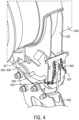
FIG. 4 is an isometric view of the unload tube of the combine ofFIG. 1 shown docked to the cradle and unlocked from the cradle. -
FIG. 5 is an isometric view of the unload tube of the combine ofFIG. 1 shown both docked and locked to the cradle of the combine. - Corresponding reference characters indicate corresponding parts throughout the several views. The exemplifications set out herein illustrate embodiments of the invention, and such exemplifications are not to be construed as limiting the scope of the invention in any manner.
- The terms "grain", "straw" and "tailings" are used principally throughout this specification for convenience but it is to be understood that these terms are not intended to be limiting. Thus "grain" refers to that part of the crop material which is threshed and separated from the discardable part of the crop material, which is referred to as non-grain crop material, MOG or straw. Incompletely threshed crop material is referred to as "tailings". Also the terms "forward", "rearward", "left" and "right", when used in connection with the agricultural harvester and/or components thereof are usually determined with reference to the direction of forward operative travel of the harvester, but again, they should not be construed as limiting. The terms "longitudinal" and "transverse" are determined with reference to the fore-and-aft direction of the agricultural harvester and are equally not to be construed as limiting.
- Referring now to the drawings, and more particularly to
FIG. 1 , there is shown an agricultural harvester in the form of acombine 10, which generally includes achassis 12, groundengaging wheels header 18,feeder housing 20,operator cab 22, threshing and separatingsystem 24,cleaning system 26,grain tank 28, and unloadingconveyor 30. -
Front wheels 14 are larger flotation type wheels, andrear wheels 16 are smaller steerable wheels. Motive force is selectively applied tofront wheels 14 through a power plant in the form of adiesel engine 32 and a transmission (not shown). Althoughcombine 10 is shown as including wheels, is also to be understood that combine 10 may include tracks. -
Header 18 is mounted to the front ofcombine 10 and includes acutter bar 34 for severing crops from a field during forward motion ofcombine 10. Arotatable reel 36 feeds the crop intoheader 18, and adouble auger 38 feeds the severed crop laterally inwardly from each side towardfeeder housing 20.Feeder housing 20 conveys the cut crop to threshing and separatingsystem 24, and is selectively vertically movable using appropriate actuators, such as hydraulic cylinders (not shown). - Threshing and separating
system 24 generally includes arotor 40 at least partially enclosed by and rotatable within a corresponding perforated concave 42. The cut crops are threshed and separated by the rotation ofrotor 40 within concave 42, and larger elements, such as stalks, leaves and the like are discharged from the rear ofcombine 10. Smaller elements of crop material including grain and non-grain crop material, including particles lighter than grain, such as chaff, dust and straw, are discharged through perforations of concave 42. Threshing and separatingsystem 24 can also be a different type of system, such as a system with a transverse rotor rather than an axial rotor, etc. - Grain which has been separated by the threshing and separating
assembly 24 falls onto agrain pan 44 and is conveyed towardcleaning system 26.Cleaning system 26 may include an optional pre-cleaningsieve 46, an upper sieve 48 (also known as a chaffer sieve), a lower sieve 50 (also known as a cleaning sieve), and acleaning fan 52. Theupper sieve 48 andlower sieve 50 can be carried within a common framework. Grain onsieves fan 52 which provides an air flow through the sieves to remove chaff and other impurities such as dust from the grain by making this material airborne for discharge fromstraw hood 54 of combine 10. Grainpan 44 and pre-cleaningsieve 46 oscillate in a fore-to-aft manner to transport the grain and finer non-grain crop material to the upper surface ofupper sieve 48.Upper sieve 48 andlower sieve 50 are vertically arranged relative to each other, and likewise oscillate in a fore-to-aft manner to spread the grain acrosssieves sieves - Clean grain falls to a
clean grain auger 56 positioned crosswise below and toward the front oflower sieve 50.Clean grain auger 56 receives clean grain from eachsieve bottom pan 58 ofcleaning system 26.Clean grain auger 56 conveys the clean grain laterally to a generally vertically arrangedgrain elevator 60 for transport tograin tank 28. Tailings fromcleaning system 26 fall to atailings auger trough 62. The tailings are transported viatailings auger 64 and returnauger 66 to the upstream end ofcleaning system 26 for repeated cleaning action. A pair ofgrain tank augers 68 at the bottom ofgrain tank 28 convey the clean grain laterally withingrain tank 28 to unloadingconveyor 30 for discharge fromcombine 10. Unloadingconveyor 30 may also be referred to in the art as an unload tube. It should be understoodcombine 10 is not limited to that which is shown and described. The components and system ofcombine 10 can vary considerably without departing from the scope and spirit of the invention. -
FIG. 2 is a rear end view of thecombine 10 ofFIG. 1 showing grain unloading from unloadingconveyor 30 of combine 10 into atruck 102. Unloadingconveyor 30 is shown transversely extending and deployed outwardly in an unloading position as it unloadsgrain 70 through anunload spout 100 ofconveyor 30 and intograin truck 102. This unloading operation can occur as combine 10 andtruck 102 are moving, which is referred to as unloading "on the go", or the unloading operation can occur in a stationary manner. At the end of the unloading operation, unloadingconveyor 30 will be pivoted to a rearwardly directed transport position, extending along the adjacent side ofcombine 10. It can be noted here thattruck 102 is located a substantial distance to the side ofcombine 10, which is desired to avoid the possibility of contact withheader 18 mounted on the front ofcombine 10, particularly when unloading on the go. It should also be noted thatconveyor 30, when in the unloading position illustrated, will typically be tilted up toward the outer end thereof, at a greater angle, compared to when in the transport position, as additional height is often required to clear the top of the grain receptacle, here illustrated bytruck 102. - Turning now to
FIGs. 2 and3 , unloadingconveyor 30 includes anouter tube 200. As viewed in cross-section,outer tube 200 is not limited to a circular shape, and may take other shapes such as a square or rectangle.Outer tube 200 generally includes anelbow 202 that is rotatably mounted to a fixed mounting surface of combine, such aschassis 12 orgrain tank 28. Elbow 202 is configured to rotate aboutaxis 203.Tube 200 is fixed toelbow 202 and rotates therewith aboutaxis 203. One ormore augers 301 are positioned intube 200 for transporting grain toward unloadspout 100 that is mounted at the free end ofconveyor 30. An actuator 205 (shown schematically) is mounted to elbow 202 for rotating elbow 202 (and the entire conveyor 30) aboutaxis 203 between the stowed position (FIGs. 1 ,4 and5 ) and the deployed position (FIGs. 2-3 ).Actuator 205 may be powered hydraulically, electrically, pneumatically by a piston-cylinder arrangement, for example, oractuator 205 may be belt-driven, for example. - Turning now to
FIG. 3 ,conveyor 30 and itsouter tube 200 are shown in a deployed position whereuponconveyor 30 is decoupled and spaced apart from acradle assembly 300 ofcombine 10. Two brackets 304 are fixedly mounted to the lower end oftube 200. Each bracket 304 includes a first end (not shown) that is fixed totube 200, and a second end opposite the first end. The second end includes a bifurcated U-shaped member having two prongs 306. The top prong 306 of each bracket 304 includes a hole oropening 308. The brackets 304 are releasably mounted tocradle assembly 300 by a removable orreleasable pin 303.Pin 303 is shown exploded fromcradle assembly 300 inFIG. 3 . -
Cradle assembly 300 is mounted to aframe member 302 of combine.Frame member 302 may form part ofchassis 12 orgrain tank 28, for example.Frame member 302 may constitute a stationary mounting point ofcombine 10.Cradle assembly 300 is fixed to the top end offrame member 302 byfasteners 310. More particularly,cradle assembly 300 includes a lowerstationary cradle member 320 that is fixed to framemember 302 by thefasteners 310, and an upperpivotable cradle member 322 that is pivotably connected to the lowerstationary cradle member 320 by a pin orshaft 324 forming a pivot joint and defining a pivot axis forpivotable cradle member 322. InFIG. 3 , the upperpivotable cradle member 322 is shown rotated about that pivot axis relative to the lowerstationary cradle member 320. - Lower
stationary cradle member 320 generally includes two opposing vertical walls that are fixedly mounted together. A series of holes are disposed inmember 320, and each hole (optionally) passes through both vertical walls. A first hole is at the first end ofmember 320 for receivingshaft 324. A second hole is provided in a central region ofmember 320 for receiving a pin orshaft 327. Twoholes member 320 for selectively receivingpin 303. When thepin 303 is moved to an 'unlocked' or 'storage' position ofpin 303. Onehole 330 is disposed near the top side at the second end ofmember 320 for selectively receivingpin 303 in the 'locked' position ofpin 303. Lowerstationary cradle member 320 may be considered as forming part ofcradle assembly 300, or, alternatively,cradle member 320 may be considered as forming part offrame member 302. - Upper
pivotable cradle member 322 also includes two opposing vertical walls that are fixedly mounted together. The walls are spaced apart such that they can fit in the space between the walls oflower member 320. A series of holes are disposed inmember 320, and each hole (optionally) passes through both vertical walls. One hole receivespin 324. Twoholes member 320 for selectively receivingpin 303 in the locked position ofpin 303. A semi-circular recess or relief is disposed on the lower side ofmember 322 for engaging withpin 327.Pin 327 provides an end-stop for rotation ofpivotable cradle member 322. A curved or saddle shaped surface 326 is mounted above the vertical walls. Surface 326 that is shaped and sized to receive or contact the exterior surface oftube 200. -
Pin 303 has a U-shape, and includes twolegs Leg 303a may be shorter thanleg 303b.Pin 303 is removably connected tocradle assembly 300.Pin 303 may be connected to cradle assembly 300 in two different positions (i.e., unlocked and locked positions). The unlocked position ofpin 303 may also be referred to and considered as a storage position ofpin 303. In the unlocked/storage position ofpin 303 shown inFIG. 4 ,tube 200 is unlocked fromframe member 302 andcradle assembly 300 to prevent movement oftube 200. And, in the locked position ofpin 303 shown inFIG. 5 ,tube 200 is locked to framemember 302 andcradle assembly 300.Pin 303 may be captively connected tomember 320 bychains 307.Pin 303 may also be more generally referred to herein as a locking device. -
FIG. 4 depicts the unlocked position ofpin 303 in which thetube 200 is unlocked from theframe 302, and the upperpivotable cradle member 322 is free to rotate relative to thestationary cradle member 320. In the unlocked position ofpin 303,tube 200 can move relative to theframe 302 between the stowed position ofFIG. 1 and the deployed position ofFIG. 2 . In the unlocked position ofpin 303, theshort leg 303a ofpin 303 is positioned throughhole 329a oflower cradle member 320 and thelong leg 303b ofpin 303 is positioned throughhole 329b oflower cradle member 320. Also, thepin 327 is positioned between the prongs 306 of the brackets 304. In the unlocked position ofpin 303, thepin 303 is not engaged with upperpivotable cradle member 322 or brackets 304 oftube 200. It is also conceivable that, in the unlocked position oftube 200,pin 303 may simply be removed fromcombine 10 as opposed to being captively connected to cradle assembly 300 as described above. -
FIG. 5 depicts the locked position ofpin 303 in which thetube 200 is locked tostationary frame 302, and the upperpivotable cradle member 322 is prevented from rotating relative to the lowerstationary cradle member 320. In the locked position ofpin 303, theshort leg 303a ofpin 303 is positioned throughholes 308 in brackets 304 as well ashole 333a inupper cradle member 322; and, thelong leg 303b ofpin 303 is positioned throughhole 333b oflower cradle member 320 as well ashole 330 ofupper cradle member 322. Thus, in the locked position, pin 303 locks together bracket 304 oftube 200,lower cradle member 320 andupper cradle member 322. Accordingly,tube 200 is prevented from moving away from the stowed position. Also, it is noted that thepin 327 is positioned between the prongs 306 of the brackets 304 in the locked position ofpin 303. - In operation, starting from the arrangement of
FIG. 4 wherepin 303 is maintained in the unlocked/storage position andtube 200 is maintained in the stowed position, activatingactuator 205 causes the free end oftube 200 to rotate away fromcombine 10 toward the deployed position shown inFIG. 2 . As the free end oftube 200 rotate away fromcombine 10, the exterior surface oftube 200 causesupper cradle member 322 to pivot with respect to lower cradle member 320 (about pin 324) to the rotated position shown inFIG. 3 . The exterior surface oftube 200 ultimately releases from saddle-shaped surface 326 astube 200 moves to the position shown inFIG. 3 .Upper cradle member 322 may or may not remain in the pivoted position after thetube 200 has detached fromcradle assembly 300. - When it is desired to return the
tube 200 to the stowed position, theactuator 205 is activated again to cause the free end oftube 200 to rotate toward combine 10 (i.e., toward the stowed position shown inFIG. 2 ). As the free end oftube 200 rotates towardcombine 10, the exterior surface oftube 200 contacts the saddle-shaped surface 326 ofupper cradle member 322 which causes theupper cradle member 322 to rotate with respect to lower cradle member 320 (about pin 324) in the direction ofarrow 340 to the position shown inFIGs. 4 and5 . The brackets 304 move towardpin 327 such thatpin 327 becomes positioned between the prongs 306 of the brackets 304. The user then moves thepin 303 to the locked position. In the locked position ofpin 303, theshort leg 303a ofpin 303 is positioned throughholes 308 in brackets 304 as well ashole 333a inupper cradle member 322, and thelong leg 303b ofpin 303 is positioned throughhole 330 oflower cradle member 320 as well ashole 333b ofupper cradle member 322. And, in the locked position, pin 303 locks together bracket 304 oftube 200,lower cradle member 320 andupper cradle member 322. Accordingly,tube 200 is prevented from moving away from the stowed position. - A
sensor 350 may be mounted toframe member 302,stationary cradle member 320 and/or pivotableupper cradle member 322 for tracking the position ofpivotable cradle member 322.Sensor 350 may be a proximity sensor, a potentiometer, a Hall-effect sensor, a photodiode, a linear encoder, a rotary encoder, and so forth. -
Pin 303 may be manually moveable between the locked and unlocked positions, as described above, or, alternatively, pin 303 may be replaced with electronically activated pin(s) or other locking device that move between the locked and unlocked positions, as described. For example, the electronically-activated pins may form part of a solenoid or hydraulic device. The solenoid or hydraulic device may be controlled remotely, e.g., from theoperator cab 22 of thecombine 10.
Claims (15)
- A combine harvester (10) comprising:a frame member (302);an unload tube (200) that is configured for expelling clean grain from a clean grain tank (28) of the combine harvester, the unload tube (200) being moveable relative to the clean grain tank and the frame member between a stowed position and a deployed position; characterized in that the combine harvester further comprises:a pivotable cradle member (322) that is pivotably mounted with respect to the frame member (302) for releasably receiving the unload tube (200), wherein the pivotable cradle member (322) comprises a surface (326) that is shaped for bearing on an exterior surface of the unload tube (200), wherein the pivotable cradle member (322) is pivotable between a first rotational position when the unload tube is maintained in the stowed position and a second rotational position when the unload tube is maintained in the deployed position; anda locking device (303) for locking together the unload tube (200), the frame member (302) and the pivotable cradle member (322) when the unload tube (200) is maintained in the stowed position.
- The combine harvester according to claim 1, further comprising a stationary cradle member (320) that is either fixedly connected to or forms part of the frame member (302), wherein the pivotable cradle member (322) is pivotably mounted to the stationary cradle member (320).
- The combine harvester according to claim 2, wherein each cradle member (320, 322) includes two vertically oriented opposing walls and a plurality of holes (329a/b, 330, 333a/b) extending through the vertical walls.
- The combine harvester according to claim 2, further comprising a first hole (333a/b) disposed in the pivotable cradle member (322), a second hole (330) disposed in the stationary cradle member (320), and a third hole (308) disposed in the unload tube (200).
- The combine harvester according to claim 4, wherein the locking device (303) is a pin, and in a locked position of the pin, the pin is configured to pass through the first, second and third holes (333a/b, 330, 308) for locking the unload tube (200) to the pivotable cradle member (322), the stationary cradle member (320) and the frame member (302).
- The combine harvester according to claim 4 or 5, further comprising a bracket (304) extending from the unload tube (200), wherein the third hole (308) is disposed in the bracket (304).
- The combine harvester according to claim 5 or 6, further comprising a fourth hole (329a/b) disposed in the stationary cradle member (320), wherein in an unlocked position of the pin (303), the pin is configured to be positioned in the fourth hole (329a/b) but not in the first, second and third holes (333a/b, 330, 308).
- The combine harvester according to any of the claims 5 to 7, wherein the pin (303) has two legs (303a/b), wherein in the locked position of the pin (303), one leg (303b) of the pin is positioned in the first and second holes (333b, 330) and the other leg (303a) of the pin is positioned in the third hole (308).
- The combine harvester according to any of the claims 5 to 8, wherein the pin (303) is manually movable to the locked position.
- The combine harvester according to claim 6, wherein the bracket has a bifurcated end, and the combine harvester further comprising a shaft (327) mounted to the stationary cradle member (320) the shaft being sized to be positioned between prongs (306) of the bifurcated end of the bracket (304).
- The combine harvester according to any one of the foregoing claims, wherein the locking device (303) is either manually or electronically activated to move to a locking position for locking together the unload tube (200), the frame member (302) and the pivotable cradle member (322).
- The combine harvester according to claim 11, wherein the locking device (303) is activated by a solenoid or hydraulic device.
- The combine harvester according to claim 12, wherein the solenoid or hydraulic device are activated by a controller in an operator cab of the combine harvester.
- The combine harvester according to any one of the foregoing claims, further comprising a sensor (350) for sensing a rotational position of the pivotable cradle member (322).
- The combine harvester according to any one of the foregoing claims, wherein the frame member (302) forms part of a chassis (12) of the combine harvester or the clean grain tank (28).
Applications Claiming Priority (1)
| Application Number | Priority Date | Filing Date | Title |
|---|---|---|---|
| US18/233,387 US12588602B2 (en) | 2023-08-14 | 2023-08-14 | Unload tube lock for agricultural vehicle |
Publications (2)
| Publication Number | Publication Date |
|---|---|
| EP4512224A1 true EP4512224A1 (en) | 2025-02-26 |
| EP4512224B1 EP4512224B1 (en) | 2026-04-01 |
Family
ID=92295936
Family Applications (1)
| Application Number | Title | Priority Date | Filing Date |
|---|---|---|---|
| EP24193648.3A Active EP4512224B1 (en) | 2023-08-14 | 2024-08-08 | Unload tube lock for agricultural vehicle |
Country Status (2)
| Country | Link |
|---|---|
| US (1) | US12588602B2 (en) |
| EP (1) | EP4512224B1 (en) |
Citations (6)
| Publication number | Priority date | Publication date | Assignee | Title |
|---|---|---|---|---|
| US3521768A (en) * | 1968-07-02 | 1970-07-28 | Deere & Co | Support for a grain tank discharge pipe |
| US4522552A (en) * | 1982-06-03 | 1985-06-11 | Pietro Laverda S.P.A. | Combine harvesters |
| DE19802199A1 (en) * | 1998-01-22 | 1999-07-29 | Ernst Dipl Ing Schumacher | Combine harvester grain tank discharger |
| JP2005176697A (en) * | 2003-12-18 | 2005-07-07 | Kubota Corp | Combine harvester support mechanism |
| EP2489253A1 (en) * | 2011-02-17 | 2012-08-22 | LAVERDA S.p.A. | Combine harvester unloading system |
| US10448568B2 (en) * | 2015-10-14 | 2019-10-22 | Cnh Industrial America Llc | Automatically securing unloading auger support |
Family Cites Families (4)
| Publication number | Priority date | Publication date | Assignee | Title |
|---|---|---|---|---|
| US2743571A (en) | 1952-10-09 | 1956-05-01 | Int Harvester Co | Grain tank discharge conveyor for harvesters |
| US4094254A (en) * | 1976-12-27 | 1978-06-13 | Koranda Clarence J | Lock for railway hopper car gate railway car gate lock |
| US5876176A (en) * | 1996-05-10 | 1999-03-02 | Unverferth Manufacturing Co., Inc. | Stowage latch assembly for auger |
| US6981833B2 (en) | 2002-07-19 | 2006-01-03 | Cnh America Llc | Work vehicle with dual mode unloader apparatus and method |
-
2023
- 2023-08-14 US US18/233,387 patent/US12588602B2/en active Active
-
2024
- 2024-08-08 EP EP24193648.3A patent/EP4512224B1/en active Active
Patent Citations (6)
| Publication number | Priority date | Publication date | Assignee | Title |
|---|---|---|---|---|
| US3521768A (en) * | 1968-07-02 | 1970-07-28 | Deere & Co | Support for a grain tank discharge pipe |
| US4522552A (en) * | 1982-06-03 | 1985-06-11 | Pietro Laverda S.P.A. | Combine harvesters |
| DE19802199A1 (en) * | 1998-01-22 | 1999-07-29 | Ernst Dipl Ing Schumacher | Combine harvester grain tank discharger |
| JP2005176697A (en) * | 2003-12-18 | 2005-07-07 | Kubota Corp | Combine harvester support mechanism |
| EP2489253A1 (en) * | 2011-02-17 | 2012-08-22 | LAVERDA S.p.A. | Combine harvester unloading system |
| US10448568B2 (en) * | 2015-10-14 | 2019-10-22 | Cnh Industrial America Llc | Automatically securing unloading auger support |
Also Published As
| Publication number | Publication date |
|---|---|
| US20250057082A1 (en) | 2025-02-20 |
| EP4512224B1 (en) | 2026-04-01 |
| US12588602B2 (en) | 2026-03-31 |
Similar Documents
| Publication | Publication Date | Title |
|---|---|---|
| US11277969B2 (en) | Adjusting system for fingerstyle grates of an agricultural harvester | |
| US10588261B2 (en) | Residue handling system for an agricultural harvester | |
| EP3707987B1 (en) | Sieve for an agricultural harvester with adjustable louvers and associated adjustment assembly | |
| US10111384B2 (en) | Agricultural chopper with linked counter knives and shear bar | |
| US12477979B2 (en) | Moveable panel for bypassing chopper of agricultural vehicle | |
| EP2745673B1 (en) | Combine side-shake control system slider joint | |
| EP3172959A1 (en) | Chopper and spreader for an agricultural harvester | |
| US11259466B2 (en) | Agricultural elevator supplied by multiple cross augers | |
| EP4491007A1 (en) | Unload spout for agricultural vehicle | |
| EP4512224B1 (en) | Unload tube lock for agricultural vehicle | |
| EP4494440B1 (en) | Lift system for bubble up auger of combine harvester | |
| EP3618603B1 (en) | Over-center locking system for a chaff pan of an agricultural harvester | |
| US10448568B2 (en) | Automatically securing unloading auger support | |
| EP4385307A1 (en) | Grain tank reinforcement for agricultural vehicle | |
| CN117413679B (en) | Integrated lifting device in combine harvester trailer | |
| EP4501098A1 (en) | Unload tube swing cylinder mount for agricultural vehicle | |
| EP3157319B1 (en) | Straw walker arrangement for an agricultural harvester | |
| EP4461118A1 (en) | Unload tube for agricultural vehicle |
Legal Events
| Date | Code | Title | Description |
|---|---|---|---|
| PUAI | Public reference made under article 153(3) epc to a published international application that has entered the european phase |
Free format text: ORIGINAL CODE: 0009012 |
|
| STAA | Information on the status of an ep patent application or granted ep patent |
Free format text: STATUS: THE APPLICATION HAS BEEN PUBLISHED |
|
| AK | Designated contracting states |
Kind code of ref document: A1 Designated state(s): AL AT BE BG CH CY CZ DE DK EE ES FI FR GB GR HR HU IE IS IT LI LT LU LV MC ME MK MT NL NO PL PT RO RS SE SI SK SM TR |
|
| STAA | Information on the status of an ep patent application or granted ep patent |
Free format text: STATUS: REQUEST FOR EXAMINATION WAS MADE |
|
| 17P | Request for examination filed |
Effective date: 20250826 |
|
| GRAP | Despatch of communication of intention to grant a patent |
Free format text: ORIGINAL CODE: EPIDOSNIGR1 |
|
| STAA | Information on the status of an ep patent application or granted ep patent |
Free format text: STATUS: GRANT OF PATENT IS INTENDED |
|
| RIC1 | Information provided on ipc code assigned before grant |
Ipc: A01D 41/12 20060101AFI20251028BHEP |
|
| INTG | Intention to grant announced |
Effective date: 20251107 |
|
| GRAS | Grant fee paid |
Free format text: ORIGINAL CODE: EPIDOSNIGR3 |
|
| GRAA | (expected) grant |
Free format text: ORIGINAL CODE: 0009210 |
|
| STAA | Information on the status of an ep patent application or granted ep patent |
Free format text: STATUS: THE PATENT HAS BEEN GRANTED |
|
| AK | Designated contracting states |
Kind code of ref document: B1 Designated state(s): AL AT BE BG CH CY CZ DE DK EE ES FI FR GB GR HR HU IE IS IT LI LT LU LV MC ME MK MT NL NO PL PT RO RS SE SI SK SM TR |
|
| REG | Reference to a national code |
Ref country code: CH Ref legal event code: F10 Free format text: ST27 STATUS EVENT CODE: U-0-0-F10-F00 (AS PROVIDED BY THE NATIONAL OFFICE) Effective date: 20260401 Ref country code: GB Ref legal event code: FG4D |
|
| REG | Reference to a national code |
Ref country code: DE Ref legal event code: R096 Ref document number: 602024003601 Country of ref document: DE |
|
| REG | Reference to a national code |
Ref country code: IE Ref legal event code: FG4D |