EP4510429A1 - Method and apparatus for cooling a rotor assembly - Google Patents
Method and apparatus for cooling a rotor assembly Download PDFInfo
- Publication number
- EP4510429A1 EP4510429A1 EP23204294.5A EP23204294A EP4510429A1 EP 4510429 A1 EP4510429 A1 EP 4510429A1 EP 23204294 A EP23204294 A EP 23204294A EP 4510429 A1 EP4510429 A1 EP 4510429A1
- Authority
- EP
- European Patent Office
- Prior art keywords
- wall
- rotor
- collar
- radially
- disc
- Prior art date
- Legal status (The legal status is an assumption and is not a legal conclusion. Google has not performed a legal analysis and makes no representation as to the accuracy of the status listed.)
- Pending
Links
Images





Classifications
-
- H—ELECTRICITY
- H02—GENERATION; CONVERSION OR DISTRIBUTION OF ELECTRIC POWER
- H02K—DYNAMO-ELECTRIC MACHINES
- H02K9/00—Arrangements for cooling or ventilating
- H02K9/19—Arrangements for cooling or ventilating for machines with closed casing and closed-circuit cooling using a liquid cooling medium, e.g. oil
-
- H—ELECTRICITY
- H02—GENERATION; CONVERSION OR DISTRIBUTION OF ELECTRIC POWER
- H02K—DYNAMO-ELECTRIC MACHINES
- H02K9/00—Arrangements for cooling or ventilating
- H02K9/19—Arrangements for cooling or ventilating for machines with closed casing and closed-circuit cooling using a liquid cooling medium, e.g. oil
- H02K9/193—Arrangements for cooling or ventilating for machines with closed casing and closed-circuit cooling using a liquid cooling medium, e.g. oil with provision for replenishing the cooling medium; with means for preventing leakage of the cooling medium
-
- H—ELECTRICITY
- H02—GENERATION; CONVERSION OR DISTRIBUTION OF ELECTRIC POWER
- H02K—DYNAMO-ELECTRIC MACHINES
- H02K1/00—Details of the magnetic circuit
- H02K1/06—Details of the magnetic circuit characterised by the shape, form or construction
- H02K1/22—Rotating parts of the magnetic circuit
- H02K1/32—Rotating parts of the magnetic circuit with channels or ducts for flow of cooling medium
-
- H—ELECTRICITY
- H02—GENERATION; CONVERSION OR DISTRIBUTION OF ELECTRIC POWER
- H02K—DYNAMO-ELECTRIC MACHINES
- H02K15/00—Processes or apparatus specially adapted for manufacturing, assembling, maintaining or repairing of dynamo-electric machines
- H02K15/08—Forming windings by laying conductors into or around core parts
-
- H—ELECTRICITY
- H02—GENERATION; CONVERSION OR DISTRIBUTION OF ELECTRIC POWER
- H02K—DYNAMO-ELECTRIC MACHINES
- H02K3/00—Details of windings
- H02K3/04—Windings characterised by the conductor shape, form or construction, e.g. with bar conductors
- H02K3/24—Windings characterised by the conductor shape, form or construction, e.g. with bar conductors with channels or ducts for cooling medium between the conductors
-
- H—ELECTRICITY
- H02—GENERATION; CONVERSION OR DISTRIBUTION OF ELECTRIC POWER
- H02K—DYNAMO-ELECTRIC MACHINES
- H02K3/00—Details of windings
- H02K3/46—Fastening of windings on the stator or rotor structure
-
- H—ELECTRICITY
- H02—GENERATION; CONVERSION OR DISTRIBUTION OF ELECTRIC POWER
- H02K—DYNAMO-ELECTRIC MACHINES
- H02K3/00—Details of windings
- H02K3/46—Fastening of windings on the stator or rotor structure
- H02K3/50—Fastening of winding heads, equalising connectors, or connections thereto
- H02K3/51—Fastening of winding heads, equalising connectors, or connections thereto applicable to rotors only
-
- H—ELECTRICITY
- H02—GENERATION; CONVERSION OR DISTRIBUTION OF ELECTRIC POWER
- H02K—DYNAMO-ELECTRIC MACHINES
- H02K7/00—Arrangements for handling mechanical energy structurally associated with dynamo-electric machines, e.g. structural association with mechanical driving motors or auxiliary dynamo-electric machines
- H02K7/18—Structural association of electric generators with mechanical driving motors, e.g. with turbines
- H02K7/1807—Rotary generators
- H02K7/1823—Rotary generators structurally associated with turbines or similar engines
-
- F—MECHANICAL ENGINEERING; LIGHTING; HEATING; WEAPONS; BLASTING
- F05—INDEXING SCHEMES RELATING TO ENGINES OR PUMPS IN VARIOUS SUBCLASSES OF CLASSES F01-F04
- F05D—INDEXING SCHEME FOR ASPECTS RELATING TO NON-POSITIVE-DISPLACEMENT MACHINES OR ENGINES, GAS-TURBINES OR JET-PROPULSION PLANTS
- F05D2220/00—Application
- F05D2220/70—Application in combination with
- F05D2220/76—Application in combination with an electrical generator
-
- H—ELECTRICITY
- H02—GENERATION; CONVERSION OR DISTRIBUTION OF ELECTRIC POWER
- H02K—DYNAMO-ELECTRIC MACHINES
- H02K1/00—Details of the magnetic circuit
- H02K1/06—Details of the magnetic circuit characterised by the shape, form or construction
- H02K1/22—Rotating parts of the magnetic circuit
- H02K1/26—Rotor cores with slots for windings
-
- H—ELECTRICITY
- H02—GENERATION; CONVERSION OR DISTRIBUTION OF ELECTRIC POWER
- H02K—DYNAMO-ELECTRIC MACHINES
- H02K19/00—Synchronous motors or generators
- H02K19/16—Synchronous generators
-
- H—ELECTRICITY
- H02—GENERATION; CONVERSION OR DISTRIBUTION OF ELECTRIC POWER
- H02K—DYNAMO-ELECTRIC MACHINES
- H02K3/00—Details of windings
- H02K3/46—Fastening of windings on the stator or rotor structure
- H02K3/50—Fastening of winding heads, equalising connectors, or connections thereto
-
- H—ELECTRICITY
- H02—GENERATION; CONVERSION OR DISTRIBUTION OF ELECTRIC POWER
- H02K—DYNAMO-ELECTRIC MACHINES
- H02K3/00—Details of windings
- H02K3/46—Fastening of windings on the stator or rotor structure
- H02K3/52—Fastening salient pole windings or connections thereto
- H02K3/527—Fastening salient pole windings or connections thereto applicable to rotors only
-
- H—ELECTRICITY
- H02—GENERATION; CONVERSION OR DISTRIBUTION OF ELECTRIC POWER
- H02K—DYNAMO-ELECTRIC MACHINES
- H02K5/00—Casings; Enclosures; Supports
- H02K5/04—Casings or enclosures characterised by the shape, form or construction thereof
- H02K5/20—Casings or enclosures characterised by the shape, form or construction thereof with channels or ducts for flow of cooling medium
- H02K5/203—Casings or enclosures characterised by the shape, form or construction thereof with channels or ducts for flow of cooling medium specially adapted for liquids, e.g. cooling jackets
-
- H—ELECTRICITY
- H02—GENERATION; CONVERSION OR DISTRIBUTION OF ELECTRIC POWER
- H02K—DYNAMO-ELECTRIC MACHINES
- H02K99/00—Subject matter not provided for in other groups of this subclass
- H02K99/10—Generators
Definitions
- Electric machines such as electric motors or electric generators, are used in energy conversion. Such electrical machines operate through the interaction of magnetic fields, and current carrying conductors generate the force or electricity respectively.
- an electrical motor converts electrical energy into mechanical energy.
- an electrical generator converts mechanical energy into electrical energy.
- aspects of the disclosure can be implemented in any environment using an electric machine regardless of whether the electric machine provides a driving force or generates electricity.
- an electric motor will be generally referred to as an electric machine, electric machine assembly, or similar language, which is meant to clarify that one or more stator/rotor combinations can be included in the machine. While this description is primarily directed toward an electric machine providing power generation, it is also applicable to an electric machine providing a driving force or an electric machine providing both a driving force and power generation. Further, while this description is primarily directed toward an aircraft environment, aspects of the disclosure are applicable in any environment using an electric machine. Thus, a brief summary of a contemplated environment should aid in a more complete understanding.
- axial refers to a dimension along a longitudinal axis of a generator or along a longitudinal axis of a component disposed within the generator.
- radial refers to a dimension extending between a center longitudinal axis, an outer circumference, or a circular or annular component disposed thereof.
- proximal refers to moving in a direction toward the center longitudinal axis, or a component being relatively closer to the center longitudinal axis as compared to another component.
- a "wet” cavity generator includes a cavity housing the rotor and stator that is exposed to free liquid coolant (e.g., coolant freely moving within the cavity).
- a “dry” cavity generator the rotor and stator can be cooled by coolant contained within limited in fluidly sealed passages (e.g., non-freely moving about the cavity).
- underlie denotes a relative position radially closer to a rotational axis of a rotatable shaft.
- overlie denotes a relative position radially farther from the rotational axis of the rotatable shaft.
- electrically insulative refers to a material that exhibits a low electrical conductivity (for example, less than about 10-8 siemens per meter (S/m)).
- the rotor assembly can include a rotatable element defining a central rotational axis and defining a periphery.
- a set of rotor windings can be wound about the periphery.
- exemplary aspects will be described herein in the form of an electrical machine, specifically a generator, for a gas turbine engine and having a rotor assembly. It will be appreciated, however, that the electrical machine can be in the form of a generator, a motor, a permanent magnet generator (PMG), or a starter/generator (S/G), and the like, in non-limiting examples.
- PMG permanent magnet generator
- S/G starter/generator
- conventional wound-rotor generators are a major source of electrical energy for industrial and commercial applications. They are commonly used to convert the mechanical power output of steam turbines, gas turbines, reciprocating engines and hydro turbines into electrical power.
- these electrical machines include a central rotatable assembly or "rotor” that is circumscribed by a stationary assembly or “stator”. A small air gap separates the rotor and stator.
- the rotor includes a rotatable shaft and a "rotor core" having one or more sets of conductive rotor windings.
- the rotor windings can be axially wound around a set of posts or rotor teeth defining slots therebetween.
- the number of sets of rotor windings typically define the number of electrical phases of the electrical machine.
- a portion of the windings (e.g., an end turn portion) of conventional rotors typically extend past or overhang the rotor.
- the rotor winding end turns in some electric machines are supported and/or covered by a housing, cover, or other structure.
- the rotor core can be oil cooled.
- the rotor core of conventional electric machines is driven to rotate by a source of rotation, such as a mechanical or electrical machine, which for some aircraft may be a gas turbine engine.
- a source of rotation such as a mechanical or electrical machine, which for some aircraft may be a gas turbine engine.
- the rotors are often rotated at relatively high revolutions per minute (rpm) (e.g., 20,000 -500,000 rpm).
- rotors typically require rugged construction to tolerate such forces over long periods of time, and despite this rugged construction, such rotors typically need to remain balanced to minimize vibration of the rotor windings, to reduce the risk of failures associated with improper balancing and deflection or relative movement of the rotor windings at high rotational speeds.
- conventional rotor end windings support structures are typically not continuous in the winding end turn region, with open areas or gaps within or between supporting elements. At higher rotational speeds, such discontinuous architectures in the winding end turn support structures can result in windage losses. Windage losses limit or reduce the operating efficiency of the generator, resulting in a need for additional oil cooling or a reduction in operating speed.
- heat is generated in the rotor due to the flow of current through the windings, and changing magnetic fields present in the rotor, causing the temperature to rise in the rotor. It is desirable to cool the rotor to protect the electrical machine from heat related damage and to increase the electrical machine power density to allow for more power from a smaller physically sized electric motor.
- FIG. 1 illustrates a gas turbine engine 10 having an accessory gear box (AGB) 12 and an electrical machine or generator 14 according to an aspect of the disclosure.
- the gas turbine engine 10 can be a turbofan engine, such as a General Electric GEnx or CF6 series engine, commonly used in modern commercial and military aviation or it could be a variety of other known gas turbine engines such as a turboprop or turboshaft.
- the AGB 12 can be coupled to a turbine shaft (not shown) of the gas turbine engine 10 by way of a mechanical power take off 16.
- the gas turbine engine 10 can be any suitable gas turbine engine used in modern aviation or it could be a variety of other known gas turbine engines such as a turboprop or turboshaft.
- gas turbine engine 10 The type and specifics of the gas turbine engine 10 are not germane to the disclosure and will not be described further herein. While a generator 14 is shown and described, aspects of the disclosure are not so limited, and aspects can include any electrical machine, such as, without limitation, a motor, or generator.
- FIG. 2 more clearly illustrates a non-limiting example of generator 14 and its housing 18 in accordance with aspects of the disclosure.
- the generator 14 can include a clamping interface 20, used to clamp the generator 14 to the AGB (not shown). Multiple electrical connections can be provided on the exterior of the generator 14 to provide for the transfer of electrical power to and from the generator 14. The electrical connections can be further connected by cables to an electrical power distribution node of an aircraft having the gas turbine engine 10 to power various items on the aircraft, such as lights and seat-back monitors.
- the generator 14 can include a liquid coolant system for cooling or dissipating heat generated by components of the generator 14 or by components proximate to the generator 14, one non-limiting example of which can be the gas turbine engine 10.
- the generator 14 can include a liquid cooling system using oil as a coolant.
- the liquid cooling system can include a cooling fluid inlet port 82 and a cooling fluid outlet port 84 for controlling the supply of coolant to the generator 14.
- the cooling fluid inlet port 82 and cooling fluid outlet port 84 can be utilized for cooling at least a portion of a rotor or stator of the generator 14.
- the liquid cooling system can also include a second coolant outlet port 91, shown at a rotatable shaft portion of the generator 14.
- the liquid cooling system can include a rotatable shaft coolant inlet port 94 or a generator coolant outlet port 95.
- aspects of the disclosure can further include other liquid cooling system components, such as a liquid coolant reservoir fluidly coupled with the cooling fluid inlet port 82, the rotatable shaft coolant inlet port 94, the cooling fluid outlet port 84, or the generator coolant outlet port 95, and a liquid coolant pump (not shown) to forcibly supply the coolant through the ports 82, 84, 94, 95 or generator 14.
- a liquid coolant reservoir fluidly coupled with the cooling fluid inlet port 82, the rotatable shaft coolant inlet port 94, the cooling fluid outlet port 84, or the generator coolant outlet port 95
- a liquid coolant pump not shown
- FIG. 3 is a cross-sectional view of the generator 14 shown in FIG. 2 taken along line III-III.
- a rotatable shaft 40 is located within the generator 14 and is the primary structure for supporting a variety of components.
- the rotatable shaft 40 can have a single diameter or one that can vary along its length.
- the rotatable shaft 40 is supported by spaced bearings 42 and 44 and configured to rotate about a rotational axis 41.
- Several of the elements of the generator 14 have a fixed component and a rotating component, with the fixed component fixed relative to the housing 18 and with the rotating component being provided on, or rotatably fixed relative to the rotatable shaft 40.
- Examples of these elements can include an electrical machine 50, housed within a cavity 51.
- the rotating component can comprise a rotor 52, and the corresponding fixed component comprises a stator 54 or stator core. In this manner, the rotor 52 is disposed on and corotates with the rotatable shaft 40.
- the fixed components can be mounted to any suitable part of the housing 18. Collectively, the fixed components define an interior through which the rotatable shaft 40 extends and rotates relative thereto.
- the rotor 52 can have a set of rotor poles
- the stator 54 can have a set of stator poles.
- the set of rotor poles can generate a set of magnetic fields relative to the set of stator poles, such that the rotation of the rotor magnetic fields relative to the stator poles generate current in the respective stator components.
- At least one of the rotor poles and stator poles can be formed by a core with a post and wire wound about the post to form a rotor winding or coil, with the rotor winding having at least one winding end turn.
- Aspects of the disclosure shown include at least one set of stator windings 90 arranged longitudinally along the housing 18, that is, in parallel with housing 18 and the rotational axis 41.
- the set of stator windings 90 can also include a set of stator winding end turns 92 extending axially beyond opposing ends of a longitudinal length of a stator 54.
- the components of the generator 14 can be any combination of known generators.
- the 50 can be either a synchronous or asynchronous generator.
- there can be other accessories driven from the same rotatable shaft 40 such as the liquid coolant pump, a fluid compressor, or a hydraulic pump.
- the generator 14 can use a cooling fluid, such as oil, as a coolant, and thus can include a cooling system 80.
- the cooling fluid or oil can be used to dissipate heat generated by the electrical and mechanical functions of the generator 14.
- the cooling system 80 using a cooling fluid can also provide for lubrication of the generator 14.
- the generator 14 can be an oil-cooled, wet cavity type cooling system 80 including the cooling fluid inlet port 82 and the cooling fluid outlet port 84 for controlling the supply of the cooling fluid to the cooling system 80.
- the cooling system 80 can further include, for example, a cooling fluid reservoir 86 and various cooling passages.
- the rotatable shaft 40 can provide one or more channels or paths for coolant or fluid coolant flow 85 (shown schematically as arrows) for the rotor 52, as well as the second coolant outlet port 91, wherein residual, unused, or unspent oil can be discharged from the rotatable shaft 40.
- the fluid coolant flow 85 can further be directed, exposed, sprayed, or otherwise deposited onto the set of stator windings 90, the set of stator winding end turns 92, or onto alternative or additional components.
- the fluid coolant flow 85 can flow from the rotatable shaft 40 radially outward toward the set of stator windings 90 or the set of stator winding end turns 92. In this sense, the coolant can cool the respective set of stator windings 90 or set of stator winding end turns 92.
- FIG. 4 illustrates a partially exploded perspective view of a rotor assembly 96 such as for a main electrodynamic machine, with some parts omitted for clarity.
- the rotor assembly 96 can include a rotor core 100, such as a laminated rotor core 100, rotatably connected to co-rotate with the rotatable shaft 40 about the rotational axis 41.
- the rotor assembly 96 can include at least one end winding support assembly 140.
- the end winding support assembly 140 is coupled to the rotatable shaft 40 for rotation therewith.
- Each end winding support assembly 140 can respectively include a first collar 141, a second collar 142, a coupling disc 143, and a support disc 144, respectively.
- the end winding support assembly 140 can include a coolant distribution ring 145. Further, in still other aspects, the end winding support assembly can include a spacer disc 146.
- the first collar 141 can include a first wall 151 and a second wall 152.
- the second collar 142 can include a third wall 253 and a fourth wall 254.
- the coupling disc 143 can include a fifth wall 155 and a sixth wall 156.
- each of the first, second, third, fourth, fifth, and sixth walls 151-156 can be annular.
- the rotor assembly 96 can further define an axial first end 102 and an axial second end 104, axially spaced from the first end 102.
- the rotor assembly 96 can include at least one rotor pole 106 defined by a rotor post 108 and formed when at least a portion of the rotor core 100 is wound with one or more sets of conductive rotor wiring or rotor windings 110 or coils about a respective rotor post 108.
- FIG. 4 an aspect having four rotor poles 106 is shown, with three rotor poles 106 being visible in the illustration.
- rotor assembly 96 can alternatively have fewer than four rotor poles 106, or more than four rotor poles 106, without departing from the scope of the disclosure, and aspects can be adapted to rotor assemblies 96 having any desired number of rotor poles 106.
- the rotor windings 110 wound around the rotor post 108 can define a respective axial winding portion 111 extending axially along the rotor core 100, and respective rotor winding end turns 112 extending axially beyond the rotor core 100.
- each rotor post 108 can radially underlie a respective set of rotor windings 110.
- rotor windings 110 or the rotor winding end turns 112 can refer to a set of or plural windings or end turns, an end turn can include only one of the set of rotor windings 110, or only one portion of the set of rotor windings 110 extending axially beyond the rotor core 100, such as only at the first end 102 or the second end 104.
- Each set of rotor winding end turns 112 can define a respective loop or arcuate bight portion 113 overhanging or extending axially beyond the rotor core 100.
- each bight portion 113 can further define a respective channel 116 extending radially therethrough.
- each channel 116 can have a respective circumferential width defined by a circumferential width of corresponding rotor post 108.
- a set of radially extending end turn passages 114 can be defined by gaps formed between immediately adjacent rotor winding end turns 112. The rotor end turn passages 114 are arranged in fluid communication with the second collar 142 and the support disc 144.
- any geometric cross section can be included in aspects of the disclosure, including by not limited to circular, ovate, square, and the like.
- the set of rotor windings 110 includes a layer of electrically insulating material (not shown) external to, and enveloping the set of rotor windings 110, to electrically isolate the set of rotor windings 110 from another set of rotor windings 110 and nearby conductive parts.
- a respective end winding support assembly 140 can be coupled to each end of the rotatable shaft 40 of the rotor assembly 96 such that a rotation of the rotatable shaft 40 causes a rotation of the end winding support assemblies 140.
- a respective end winding support assembly 140 can be coupled to an end (e.g., either the first end 102 or the second end 104) of the rotor assembly 96.
- a respective end winding support assembly 140 can be rotatably coupled to the rotatable shaft 40 at both the first end 102 and the second end 104 of the rotor assembly 96.
- the first wall 151 can be arranged facing an end 102, 104 of the rotor core 100 and can define a first bore 161.
- the second wall 152 can be coupled to the first wall 151 and extend axially inward therefrom toward the rotor core 100.
- the second wall 152 is arranged to radially overlie a rotor winding end turn 112 of the rotor windings relative to the rotational axis 41 of the rotatable shaft 40.
- the second collar 142 can be disposed between the first collar 141 and the rotor core 100.
- the third wall 253 can be arranged confronting or facing an end 102, 104 the rotor core 100 and can define a second bore 162.
- the fourth wall 254 can be coupled to the third wall 253 and extend axially inward therefrom toward the rotor core 100.
- the fourth wall 254 is radially disposed between the rotor winding end turns 112 and the second wall 152 of the first collar 141.
- the fourth wall 254 can be further arranged to radially overlie a rotor winding end turn 112 relative to the rotational axis 41 of the rotatable shaft 40.
- the coupling disc 143 fifth wall 155 is arranged confronting or facing a respective end 102, 104 of the rotor core 100.
- the sixth wall 156 is coupled to the fifth wall 155 and extends axially therefrom toward the rotor core 100.
- the sixth wall 156 can circumferentially surround and be coupled to the rotatable shaft 40.
- the support disc 144 can circumferentially surround and be coupled to the rotatable shaft 40.
- the support disc 144 can be disposed between the rotor core 100 and the second collar 142.
- the support disc 144 can include a radially outer periphery 189.
- the radially outer periphery 189 can define a set of first slots 185 or gaps therethrough.
- the first slots 185 can be circumferentially spaced from each other about the support disc 144.
- the first slots 185 can be sized to operatively receive a respective rotor winding 110 axially therein.
- a portion of the support disc 144 can be disposed within one or more of the channels 116 defined by the rotor winding end turns 112, with the rotor winding end turns 112 disposed in a respective first slot 185.
- FIG. 4 depicts a non-limiting example of the end winding support assembly 140 configured for a 4-pole rotor assembly 96, other aspects are not so limited. It will be appreciated that aspects as disclosed herein are not limited to any specific number of rotor poles, and aspects of end winding support assembly 140 can be adapted to rotor assemblies 96 having any desired number of poles.
- FIG. 5 depicts a perspective view of the first collar 141 of FIG. 4 .
- the first wall 151 can define an axially inward-facing (e.g., facing toward the rotor core 100 of FIG.4 ) annular first surface 151a and an opposing axially outward-facing (e.g., facing away from the rotor core 100 of FIG. 4 ) annular second surface 151b.
- the first wall 151 can further include a radially inward-facing annular third surface 151c defining the first bore 161.
- the third surface 151c can extend from the first surface 151a to the second surface 151b.
- the first bore 161 can be sized to receive the rotatable shaft 40 therethrough.
- the second wall 152 can have a radially inward-facing (e.g., toward the rotor core 100 of FIG. 4 ) annular fourth surface 152a and an opposing radially outward-facing (e.g., away from the rotor core 100 of FIG. 4 ) annular fifth surface 152b.
- the fifth surface 152b can define a first diameter D1.
- FIG. 6 depicts a perspective view of the second collar 142 of FIG. 4 .
- the second collar 142 is electrically insulative.
- the third wall 253 can define an axially-inward-facing annular sixth surface 253a (e.g., facing toward the rotor core 100 of FIG. 4 ) and an opposing axially outward-facing annular seventh surface 253b (e.g., facing away from the rotor core 100 of FIG. 4 ).
- the third wall 253 can further include a radially inward-facing annular eighth surface 253c defining the second bore 162.
- the eighth surface 253c can extend axially from the sixth surface 253a to the seventh surface 253b.
- the second bore 162 can be sized to receive the rotatable shaft 40 therethrough.
- the fourth wall 254 can have a radially outward-facing ninth surface 254a (e.g., facing away from the rotor core 100 shown in FIG. 4 ) and an opposing radially inward-facing tenth surface 254b (e.g., facing toward the rotor core 100).
- the sixth surface 253a of the third wall 253 can define a set of first grooves 255 thereon.
- the first grooves 255 can have a circumferential width and extend radially across the sixth surface 253a, for example extending from the eighth surface 253c to ninth surface 254a of the fourth wall 254.
- the first grooves 255 are circumferentially spaced from each other.
- the tenth surface 254b of the fourth wall 254 can define a set of second grooves 256.
- the second grooves 256 can be arranged in fluid communication with the set of first grooves 255.
- the second grooves 256 have a circumferential width and can extend axially across the tenth surface 254b, for example extending from the sixth surface 253a to an opposing end at an axial extent of the fourth wall 254.
- the second grooves 256 are circumferentially spaced from each other.
- the second grooves 256 can be tapered.
- one or more of the second grooves 256 can be shallower at the tenth surface 254b than at the diametric end at the radial extent of the fourth wall 254.
- the first and second grooves 255, 256 can define coolant collection surfaces.
- the tenth surface 254b of the fourth wall 254 can define a set of third grooves 257.
- the third grooves 257 have an axial width and extend circumferentially along the tenth surface 254b.
- the third grooves 257 are axially spaced from each other.
- the third grooves 257 can be arranged in fluid communication with the set of second grooves 256, or the set of first grooves 255, or both.
- the third grooves 257 and second grooves 256 are arranged at an angle with respect to each other.
- the third grooves 257 can be arranged orthogonally with respect to the second grooves 256.
- the third grooves 257 can be arranged at any desired angle (e.g., non-parallel) with respect to the second grooves 256.
- the third grooves 257 can define coolant collection surfaces.
- FIG. 7A depicts a more detailed perspective view of the coupling disc 143 of FIG. 4
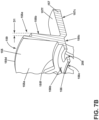
- FIG. 7B is a cross-section of a portion of the coupling disc 143 of FIG. 7A taken along line IV-IV.
- the fifth wall 155 and sixth wall 156 can cooperatively define a third bore 163 sized to receive the rotatable shaft 40 therethrough.
- the fifth wall 155 can define an axially inward-facing eleventh surface 155a (e.g., facing axially toward the rotor core 100 of FIG.
- the fifth wall 155 can further include a radially inward-facing thirteenth surface 155c (e.g., facing radially toward the rotor core 100 of FIG. 4 ) and an opposing radially outward-facing fourteenth surface 155d (e.g., facing radially away from the rotor core 100 of FIG. 4 ).
- the fourteenth surface 155d can define a radially outer periphery 159 of the coupling disc 143.
- the radially inward-facing thirteenth surface 155c can define a third bore 163.
- the thirteenth surface 155c can extend from the eleventh surface 155a to the twelfth surface 155b.
- the twelfth surface 155b can define a recess 155e or seat portion defined thereon.
- the recess 155e can be annular and arranged along the radially outer periphery 159 of the coupling disc 143 (e.g., on the twelfth surface 155b).
- the recess 155e can be recessed from an adjacent or abutting portion of the twelfth surface155b by a depth D1.
- the depth D1 can be based on a thickness of the first wall 151 of the first collar 141 (shown in FIG. 5 ).
- the recess 155e or seat portion can provide a seating surface for the first wall 151.
- the coupling disc 143 can define a lip 155f.
- the lip 155f can be coupled to the eleventh surface 155a and extend axially therefrom.
- the lip 155f is arranged to confront the eighth surface 253c of the second collar 142 (shown in FIG. 6 ).
- the lip 155f can be annular and arranged to circumferentially surround the third bore 163.
- the sixth wall 156 can extend axially inward (e.g., axially toward the rotor core 100 of FIG. 4 ) from the eleventh surface 155a.
- the sixth wall 156 can include an annular radially inward-facing fifteenth surface 156c and an opposing annular radially outward-facing sixteenth surface 156b.
- the sixth wall 156 can define a set of apertures 258 therethrough.
- the apertures 258 can extend from the fifteenth surface 156c to the sixteenth surface 156b.
- the apertures 258 can be circumferentially spaced from each other about the sixth wall 156.
- the sixth wall 156 can cooperate with the radially inward-facing thirteenth surface 155c to further define the third bore 163.
- the fifteenth surface 156c can be concentrically aligned with the thirteenth surface 155c of the fifth wall 155.
- the fifteenth surface 156c, or the thirteenth surface 155c, or both can define the third bore 163.
- the coupling disc 143 can further include an annular seventh wall 157.
- the seventh wall 157 can circumferentially surround the rotatable shaft 40.
- the seventh wall 157 can be coupled to the twelfth surface 155b and extend axially outward therefrom (e.g., facing away from the rotor core 100 of FIG.4 ).
- the seventh wall 157 can cooperate with the fifteenth surface 156c, or the thirteenth surface 155c, or both to further define the third bore 163.
- the seventh wall 157 can include an annular radially inward-facing seventeenth surface 157c and an opposing annular radially outward-facing eighteenth surface 157f.
- the seventeenth surface 157c can be concentrically aligned with the thirteenth surface 155c of the fifth wall 155.
- Fig. 8 depicts a non-limiting aspect of the support disc 144.
- the support disc 144 can comprise an annular disc having a first face 181 and an opposing second face 182.
- the first face 181 can be arranged facing or confronting an end 102, 104 of the rotor core 100 (shown in FIG. 4 ).
- the second face 182 can be axially outward-facing, (e.g., facing axially away from the rotor core 100 of FIG. 4 ).
- the support disc 144 can define a fourth bore 164 sized to receive the rotatable shaft 40 (shown in FIG. 4 ) therethrough.
- the support disc 144 can comprise a radially inward-facing, nineteenth surface 186 (e.g., facing toward the rotatable shaft 40 of FIG. 4 ).
- the support disc 144 can include a radially outwardly facing, twentieth surface 187 that opposes the nineteenth surface 186.
- the twentieth surface 187 can define a second diameter D2.
- the twentieth surface 187 can define the radially outer periphery 189.
- the nineteenth and twentieth surfaces 186, 187 can extend axially between the first face 181 and second face 182.
- the twentieth surface 187 can define the set of first slots 185 or gaps therethrough.
- the first slots 185 can be circumferentially spaced from each other about the radially outer periphery 189 of the support disc 144.
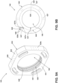
- FIG. 9A depicts a perspective view of a non-limiting aspect of the coolant distribution ring 145
- FIG. 9B depicts a cross section of another aspect of the coolant distribution ring 145.
- the coolant distribution ring 145 can comprise an annular disc having a third face 631 and an opposing fourth face 632.
- the third face 631 can be arranged facing an end 102, 104 of the rotor core 100 (shown in FIG. 4 ), and the fourth face 632 can be axially outward-facing, (e.g., facing axially away from the rotor core 100 of FIG. 4 ).
- the coolant distribution ring 145 can comprise a radially inward-facing, twenty-first surface 621 (e.g., facing toward the rotatable shaft 40 of FIG. 4 ).
- the twenty-first surface 621 can define a fifth bore 165 sized to receive the rotatable shaft 40 (shown in FIG. 4 ) therethrough.
- the coolant distribution ring 145 can include a radially outwardly facing, twenty-second surface 622 opposing the twenty-first surface 621.
- the twenty-second surface 622 can be an outer perimetric surface.
- the twenty-first surface 621 and twenty-second surface 622 can axially extend between the third face 631 and fourth face 632.
- the twenty-first surface 621 can be a relatively smooth surface.
- the twenty-first surface 621 can define a set of channels or fourth grooves 625 thereon. When assembled, the fourth grooves 625 can be arranged in fluid communication with the rotatable shaft 40 ( FIG. 4 ). As such the set of fourth grooves 625 can cooperatively define a coolant reservoir.
- the coolant distribution ring 145 can further define a set of channels 627 extending radially therethrough in fluid communication with the twenty-first surface 621.
- the channels 627 can extend from a first end 627a disposed at the twenty-first surface 621 to an opposing second end 627b at the twenty-second surface 622.
- Each channel 627 can comprise a coolant inlet 628 defined on the twenty-first surface 621, and a corresponding coolant outlet 629 defined on the twenty-second surface 622, at the opposing second end 627b.
- the channels 627 can be circumferentially spaced about the coolant distribution ring 145.
- the channels 627 can be sized to allow the fluid coolant flow 85 (not shown) therethrough.
- the channels 627 can further be in fluid communication with a respective coolant outlet 629.
- At least a subset of the coolant outlets 629 can define a respective spray nozzle 629a at a radially distal end.
- the spray nozzles 629a can be disposed at circumferentially spaced intervals on the twenty-second surface 622.
- FIG. 10 depicts a perspective view of a non-limiting aspect of the spacer disc 146.
- the spacer disc 146 can comprise an annular disc having a first face 781 and an opposing second face 782.
- the spacer disc 146 can be formed from an electrically insulative material.
- the spacer disc 146 can electrically insulate the support disc from the coolant distribution ring 145 or other electrically conductive parts.
- a radially outer surface of the spacer disc 146 can be coated with an electrically insulative material.
- the first face 781 can be arranged facing an end 102, 104 of the rotor core 100 (shown in FIG. 4 ).
- the second face 182 can be axially outward-facing, (e.g., facing axially away from the rotor core 100 of FIG. 4 ).
- the spacer disc 146 can define a sixth bore 166 sized to receive the rotatable shaft 40 (shown in FIG. 4 ) therethrough.
- the spacer disc 146 can comprise a radially inward-facing, twenty-third surface 786 (e.g., facing toward the rotatable shaft 40 of FIG. 4 ).
- the spacer disc 146 can include a radially outwardly facing, twenty-fourth surface 787 that opposes the twenty-third surface 786.
- the twenty-fourth surface 787 can define a third diameter D3.
- the third diameter D3 is less than the second diameter D2 of the support disc 144 (shown in FIG. 8 ).
- the twenty-fourth surface 787 can define a radially outer periphery 789 of the spacer disc 146.
- the twenty-third and twenty-fourth surfaces 786, 787 can axially extend between the first face 781 and second face 782.
- the twenty-fourth surface 787 can define a set of second slots 785 or gaps therethrough.
- the second slots 785 can be circumferentially spaced from each other about the radially outer periphery 789 of the spacer disc 146.
- the second slots 785 can be sized to operatively receive a respective rotor winding 110 axially therein.
- FIG. 11A depicts a perspective view of the assembled rotor assembly 96 of FIG. 4
- FIG. 11B is a cross-section of a portion of the rotor assembly 96 of FIG. 11A taken along line V-V, with some parts (e.g., the rotor winding end turns 112, and coolant distribution ring 145) omitted for clarity.
- the first wall 151 of the first collar 141 can be coupled along the third surface 151c to the fifth wall 155 of the coupling disc 143 along the radially outer periphery 159.
- the radially outward-facing fourteenth surface 155d of the fifth wall 155 can be coupled to the third surface 151c of the first collar 141.
- a radially inboard portion of the first wall 151 can be disposed in the annular recess 155e or seat portion defined along the radially outer periphery 159 of the coupling disc 143 in a nested relationship.
- the recess 155e When assembled, the recess 155e can receive a portion of the first wall 151 therein, such that the first surface 151a of the first wall 151 and the twelfth surface 155b of the fifth wall 155 can cooperatively define a continuous axially outward-facing surface 158 via the nested relationship.
- the continuous axially outward-facing surface 158 By arranging the continuous axially outward-facing surface 158, undesired gaps, openings, or other discontinuities at the corresponding end 102, 104 of the rotor core 100 can be reduced over conventional arrangements, and consequent beneficial reductions in windage losses can be obtained.
- the first collar 141 can also be coupled to the support disc 144.
- the first collar 141 can be coupled along the fifth surface 152b to the radially outer periphery 189 (e.g., the twentieth surface 187) of the support disc 144.
- the first collar 141 can be coupled to the support disc 144 via an interference, friction, or press-fit engagement between the first collar 141 and the support disc 144.
- the first diameter D1 can be arranged to be less than or equal to the second diameter D2, to enable a press fit between the second wall 152 of the first collar 141 and the fourth wall 254 of the second collar 142.
- Other aspects are not so limited, and it is contemplated that the first collar 141 can be coupled to the support disc 144 by any desired affixing mechanisms.
- the second collar 142 can optionally be coupled to the support disc 144.
- the second collar 142 can be coupled along the eighth surface 253c to the lip 155f of the coupling disc 143.
- the second collar 142 can be coupled along the eighth surface 253c to the sixteenth surface 156d of the coupling disc 143.
- the second collar 142 can be coupled to the coupling disc 143 via an interference, friction, or press-fit engagement between the second collar 142 and the coupling disc 143.
- Other aspects are not so limited, and it is contemplated that the second collar 142 can be coupled to the coupling disc 143 by any desired affixing mechanisms.
- the second collar 142 can be disposed between the first collar 141 and the support disc 144 without being coupled to the coupling disc 143.
- the coupling disc 143 is coupled to the rotatable shaft 40.
- the coupling disc 143 can be coupled to the rotatable shaft 40 via one or more of the fifth, sixth, and seventh walls 155, 156, 157 (shown in FIG. 7 ).
- the coupling disc 143 can be fixed to the rotatable shaft 40 along the radially inward-facing thirteenth surface 155c, fifteenth surface 156c, seventeenth surface 157c (shown in FIG. 7 ), or combinations thereof, using one or more bolts, screws, pins, keys, splines, or other known fasteners (not shown).
- the coupling disc 143 can be coupled to the rotatable shaft 40 via an interference, friction, or press-fit engagement between the coupling disc 143 and the rotatable shaft 40.
- Other aspects are not so limited, and it is contemplated that the coupling disc 143 can be rotatably coupled to the rotatable shaft 40 by any desired affixing mechanisms. It will be appreciated that when so coupled, a rotation of the rotatable shaft 40 will result in a corresponding rotation of the coupling disc 143.
- the support disc 144 is coupled to the rotatable shaft 40.
- the support disc 144 can be fixed to the rotatable shaft 40 along the nineteenth surface 186 using one or more bolts, screws, pins, keys, splines, or other known fasteners (not shown).
- the support disc 144 can be coupled to the rotatable shaft 40 via an interference, friction, or press-fit engagement between the support disc 144 and the rotatable shaft 40.
- Other aspects are not so limited, and it is contemplated that the support disc 144 can be rotatably coupled to the rotatable shaft 40 by any desired affixing mechanisms.
- FIG. 12 schematically illustrates a portion another exemplary aspect of the rotor assembly 96 for better understanding the arrangement and operation of various aspects.
- the aspect depicted in FIG. 12 is similar to the aspect shown in FIG. 11B with one notable difference being the second collar 142 is not coupled to the sixth wall 156 of the coupling disc 143.
- the end winding support assembly 140 includes the first collar 141, second collar 142, coupling disc 143, support disc 144, coolant distribution ring 145, and spacer disc 146.
- the coupling disc 143 and support disc 144 are shown rotatably coupled to the rotatable shaft 40.
- the first and second collars 141, 142 and coolant distribution ring 145 are shown circumferentially surrounding and coupled to the coupling disc 143.
- the coolant distribution ring 145 can be fixedly coupled to the coupling disc 143 using one or more bolts, screws, pins, keys, or other known fasteners.
- the coolant distribution ring 145 can be coupled to the coupling disc 143 via an interference, friction, or press-fit engagement between the first coolant distribution ring 145 and the coupling disc 143.
- the twenty-first surface 621 of the coolant distribution ring 145 can be fixedly coupled to the twelfth surface 155b of the coupling disc 143.
- the set of apertures 258 can be in fluid communication with the twelfth surface 155b.
- coolant distribution ring 145 can be rotatably coupled to the coupling disc 143 by any desired affixing mechanisms. It will be appreciated that when so coupled, a rotation of the coupling disc 143 will result in rotation of the coolant distribution ring 145.
- An annular gap or cavity 275 is radially defined between the outer periphery or radially outwardly facing, twenty-second surface 622 of the coolant distribution ring 145 and the radially inward-facing ninth surface 254a of the fourth wall 254 of the second collar 142.
- the cavity 275 can axially extend between the spacer disc 146 and the third wall 253 of the second collar 142.
- the rotor winding end turns 112 are disposed to extend into the cavity 275.
- the coolant distribution ring 145 is disposed to at least partially underlie the rotor winding end turns 112.
- underlie denotes a relative position radially closer to the rotational axis 41 of the rotatable shaft 40.
- the twenty-second surface 622 is arranged proximal to and facing the rotor winding end turns 112.
- the second collar 142 can at least partially overlie the rotor winding end turns 112.
- "overlie” denotes a relative position radially farther from the rotational axis 41 of the rotatable shaft 40.
- the coolant distribution ring 145 and second collar 142 can cooperatively support, or otherwise limit a radial movement of the rotor winding end turns 112 disposed within the cavity 275. Additionally, the spacer disc 146 and second collar 142 can cooperatively support, or otherwise limit an axial movement of each rotor winding end turn 112 disposed within the cavity 275.
- a portion of the rotor windings 110 axially extending from the rotor core 100 can be disposed in the set of first slots 185 of the support disc 144 and extend axially therethrough.
- a portion of each rotor winding 110 can axially extend from the rotor core 100 and axially through a respective first slot 185.
- a circumferentially width of each first slot 185 can be configured to retainably receive the rotor winding 110 therein. In this way, the support disc 144 can support, or otherwise limit a lateral movement of each rotor winding 110 disposed within a respective first slot 185.
- each rotor winding 110 can be further disposed in the set of second slots 785 to extend axially therethrough.
- a portion of each rotor winding 110 can axially extend from the rotor core 100 and axially through a respective second slot 785.
- a circumferentially width of each second slot 785 can be configured to retainably receive the rotor winding 110 therein. In this way, the spacer disc 146 can support, or otherwise limit a lateral movement of each rotor winding 110 disposed within a respective second slot 785.
- the fluid coolant flow 85 to can enter the rotatable shaft 40 of the rotor assembly 96 via one of the cooling fluid inlet ports 82, coolant inlet port 94, or both.
- the end winding support assembly 140 is arranged to enable the fluid coolant flow (indicated by solid arrows) 85 to flow radially therethrough.
- the fluid coolant flow 85 is conveyed from the rotatable shaft 40 to the cavity 275 and the set of rotor winding end turns 112.
- the fluid coolant flow 85 can subsequently be delivered from the end winding support assembly 140 axially toward the rotor core 100 or radially toward the stator windings 90, or both.
- the rotatable shaft 40 can define a first coolant conduit 250 fluidly connected with a source of coolant 251.
- the source of coolant 251 can be, but is not limited to, the cooling fluid inlet port 82 ( FIG. 3 ).
- the direction or location of the source of coolant 251 is not limited by the illustration and can be disposed in any location that is fluidly coupled to the first coolant conduit 250. It is further contemplated that additional conduit, pumps, valves, or other devices can be included to fluidly connect the source of coolant 251 and the first coolant conduit 250 without departing from the scope of the disclosure.
- the fluid coolant flow 85 can be conveyed through the rotatable shaft 40 via the first coolant conduit 250.
- the first coolant conduit 250 can include a radially extending portion 259.
- the radially extending portion 259 can fluid couple the first coolant conduit 250 and the coupling disc 143.
- the fluid coolant flow 85 can flow radially outward through the radially extending portion 259 from the rotational axis 41 toward the coupling disc 143 due to the centrifugal force effects of the rotatable shaft 40.
- the coupling disc 143 can receive the fluid coolant flow 85 from the first coolant conduit 250, via the radially extending portion 259 of the first coolant conduit 250, at the thirteenth surface 155c or fifteenth surface 156c, or both.
- the fluid coolant flow 85 can collect on or at the thirteenth surface 155c or fifteenth surface 156c, or both, and be centrifugally conveyed radially outward through the set of apertures 258 to the coolant distribution ring 145.
- the fluid coolant flow 85 can be centrifugally conveyed through the coolant distribution ring 145.
- the fluid coolant flow 85 can be centrifugally conveyed from the twenty-first surface 621 to the twenty-second surface 622 via the set of channels 627.
- the channels 627 can be in fluid communication with the rotatable shaft 40, or the set of fourth grooves 625, or both, to receive the fluid coolant flow 85 therefrom.
- the fluid coolant flow 85 can be centrifugally conveyed from the coolant distribution ring to the cavity 275.
- the coolant can be radially expelled from the channels 627 to the cavity 275 via the coolant outlets 629.
- the coolant outlets 629 are arranged to provide the fluid coolant flow 85 radially outwardly therefrom.
- the coolant outlet 629 can be configured to operatively spray finely atomized particles of coolant fluid toward the rotor winding end turns 112 and end turn passages 114 within the cavity 275.
- the fluid coolant flow 85 is centrifugally conveyed to the end turn passages 114 between the rotor winding end turns 112. Fluid can flow radially outward through the end turn passages 114 that pass between the rotor winding end turns 112 which transfers heat from the set of rotor windings 110 into the coolant by conduction.
- the fluid coolant flow 85 can be expelled radially from the rotor end turn passages 114 and received by the second collar 142.
- the fluid coolant flow 85 can be received by the sixth surface 253a of the third wall 253 or the tenth surface 254b of the fourth wall 254, or both.
- the fluid coolant flow 85 can be received in the fluid collection surfaces of second grooves 256, third grooves 257 or both.
- the fluid coolant flow 85 received in the third grooves 257 can be centrifugally conveyed to the second grooves 256.
- the fluid coolant flow 85 received in the first grooves 255 can be centrifugally conveyed to the second grooves 256.
- one or more of the second grooves 256 can be tapered along the tenth surface 254b to define an angle 268 relative to the rotational axis 41, such that the second groove 256 can receive and redirect the fluid coolant flow 85 axially outward from the rotor end turn passages 114 and toward the support disc 144, and expelled from the cavity 275.
- the fluid coolant flow 85 can be expelled radially from the second collar 142 and the radial rotor end turn passages 114.
- the fluid coolant flow 85 redirected by the second collar 142 can be delivered axially inward from the cavity 275 and through the set of first slots 185.
- FIG. 13 illustrates a method 700 of cooling the set of rotor winding end turns 112 of the rotor assembly 96.
- the method 700 can be applied to any electrical machine. While the method will be described herein, for ease of understanding, in terms of the rotor assembly 96 of FIGS. 4-11 , other aspects are not so limited and method 700 can be implemented with any electrical machine without departing from the scope of the disclosure.
- the method 700 includes disposing a set of rotor windings 110 extending from a rotor core 100 into a respective slot 185 defined in the support disc 144 coupled to the rotatable shaft 40 extending from the rotor core 100.
- the method 700 can include, at 720, coupling the first wall 151 of the first collar 141 to the coupling disc 143 circumferentially surrounding and coupled to the rotatable shaft 40, and the second wall 152 of the first collar 141 to a radially outer periphery 189 of the support disc 144.
- a non-limiting example of coupling the second wall 152 of the first collar 141 to the radially outer periphery 189 of the support disc 144 can include a press fit.
- the method 700 can include at 730, coupling the third wall 253 of the second collar 142 to the coupling disc 143, between the first wall 151 and the support disc 144.
- a non-limiting example of coupling the third wall 253 of the second collar 142 to the coupling disc 143 can include a press fit.
- the method 700 can include at 740, disposing a set of rotor winding end turns 112 into the cavity 275 extending radially between the coolant distribution ring 145 and the fourth wall 254 of the second collar 142.
- the cavity can extend axially between the support disc 144 and third wall 253 of the second collar 142.
- the cavity 275 can extend radially between the coolant distribution ring 145 and fourth wall 254 of the second collar 142.
- the method 700 can include at 745, delivering a fluid coolant flow 85 radially outward from the rotatable shaft 40 to the coupling disc 143.
- a non-limiting example of delivering the fluid coolant flow 85 to the coupling disc 143 can include delivering the fluid coolant flow 85 through the rotatable shaft 40 via the first coolant conduit 250.
- the first coolant conduit 250 can include the radially extending portion 259 through which the fluid coolant flow 85 can flow radially outward from the rotational axis 41 due to the centrifugal force effects of the rotatable shaft 40.
- the method 700 can include at 750, delivering the fluid coolant flow 85 through the coupling disc 143 to the coolant distribution ring 145.
- the fluid coolant flow 85 can be delivered radially outward through the set of apertures 258 defined through the sixth wall 156 of the coupling disc 143 due to the centrifugal force effects of the rotatable shaft 40 driving a rotation of the coupling disc 143.
- the method 700 can include at 755, delivering the fluid coolant flow 85 radially outward through the coolant distribution ring 145 to the cavity 275.
- the fluid coolant flow 85 can be delivered radially outward through the set of channels 627 extending radially through coolant distribution ring 145 due to the centrifugal force effects of the rotatable shaft 40 driving a rotation of the coolant distribution ring 145.
- the method 700 can include at 760, delivering the fluid coolant flow 85 radially through end turn passages 114 defined between adjacent rotor winding end turns 112. Heat from the set of rotor winding end turns 112 is transferred by conduction to the fluid coolant flow 85. The conduction of heat to the fluid coolant flow 85 can result in the fluid coolant flow 85 removing heat from the rotor assembly 96.
- the method 700 can include at 765, delivering the fluid coolant flow 85 from the end turn passages 114 to the fourth wall 254 of the second collar 142.
- the method 700 can include at 770, delivering the fluid coolant flow 85 from the cavity 275 through the respective slot 185 defined in the support disc 144.
- the delivering the fluid coolant flow 85 axially inward from the cavity 275 can include delivering the fluid coolant flow 85 axially inward toward the rotor core 100, or radially outward toward the stator 54, or both.
- the sequence depicted is for illustrative purposes only and is not meant to limit the method 700 in any way as it is understood that the portions of the method can proceed in a different logical order, additional or intervening portions can be included, or described portions of the method can be divided into multiple portions, or described portions of the method can be omitted without detracting from the described method.
- one aspect of the disclosure contemplates coolant conduits that extend along alternative portions or lengths of the set of rotor windings.
- the windings or the coolant conduits can further include intervening thermally conductive layers to assist in thermal conduction while, for example, avoiding an electrically conductive relationship between respective components.
- the design and placement of the various components such as valves, pumps, or conduits can be rearranged such that a number of different in-line configurations could be realized.
- aspects as disclosed herein improve upon existing methods by securing, protecting, and constraining the rotor winding end turns 112. Aspects as disclosed herein prevent movement of the rotor winding end turns 112 and provide mechanical and electrical isolation between the rotor winding end turns 112 and nearby parts.
- the aspects disclosed herein provide method and apparatus for cooling a set of rotor windings or a set of rotor winding end turns during electric machine operations (e.g., motor or generator operations).
- electric machine operations e.g., motor or generator operations.
- One advantage that may be realized in the above aspects is that the above-described aspects have significantly improved thermal conduction to remove heat from the set of rotor windings or the set of rotor winding end turns.
- the improved thermal conductivity between the set of rotor winding end turns and the coolant conduits coupled with the coolant channels provide for heat removal in a much more effective fashion from the rotor winding end turns to the coolant.
- the increased thermal dissipation of the rotor winding end turns allows for a higher speed rotation of the rotor, which may otherwise generate too much heat.
- the higher speed rotation may result in improved power generation or improved generator efficiency without increasing generator size.
- Reduced thermal losses in the electric machine allows for greater efficiency and greater power density of the generator.
- the above-described rotor end winding support assembly can provide additional physical stability and improved cooling to the rotor winding end turns.
- the stability and cooling provided by the aspects as described herein allow an increase in performance and reliability.
- a support assembly for a set of rotor winding end turns extending from a rotor core of an electrical machine having a rotatable shaft comprising: a first collar including a first wall having an annular first surface facing an axial end of the rotor core, an opposing annular second surface, and an annular third surface defining a first bore extending from the annular first surface to the annular second surface, the first collar further including an annular second wall coupled to the first wall and extending axially therefrom toward the rotor core arranged to radially overlie the rotor winding end turns, the annular second wall having an radially outward facing annular fourth surface, and an opposing annular fifth surface facing the rotor winding end turns; a second collar axially disposed between the rotor core and the first collar, including a third wall disposed between the first wall and the rotor winding end turns, the third wall having an annular sixth surface facing the axial end of the rotor core, an opposing seventh surface,
- the support assembly of any preceding clause further comprising a support disc defining a fourth bore sized to receive the rotatable shaft therethrough, and a radially outer periphery, the support disc further defining a set of radially extending first slots sized to receive a respective rotor winding axially therein, the support disc coupled to the rotatable shaft at the fourth bore, and disposed axially between the rotor core and the second collar; and wherein the annular fifth surface of the first collar is coupled to the radially outer periphery of the support disc.
- annular fifth surface of the first collar is coupled to the radially outer periphery of the support disc via an interference fit.
- a coolant distribution ring defining a central fifth bore, and circumferentially surrounding and coupled to the annular sixth wall of the coupling disc, the coolant distribution ring radially disposed between the annular sixth wall and an end turn of the rotor windings.
- coolant distribution ring includes a set of radially extending channels defined therethrough in fluid communication with the set of rotor winding end turns.
- annular sixth wall of the coupling disc defines a set of apertures extending radially therethrough in fluid communication with the coolant distribution ring.
- annular fourth wall of the second collar includes a radially inward facing tenth surface defining a set of axially extending grooves, in fluid communication with the coolant distribution ring.
- the radially inward facing tenth surface further defines a set of circumferentially extending grooves, in fluid communication with the axially extending grooves.
- the support assembly of any preceding clause further comprising a spacer disc disposed axially between the support disc and the coolant distribution ring and rotatably coupled to the rotatable shaft, the spacer disc further including a radially outer surface defining a set of radially extending, circumferentially spaced second slots sized to receive a respective rotor winding therein.
- a method of cooling a set of rotor winding end turns of a rotor core of an electrical machine comprising: disposing a set of rotor windings extending from the rotor core into a respective first slot defined in a support disc coupled to a rotatable shaft extending from the rotor core; coupling a first wall of a first collar to a coupling disc circumferentially surrounding and coupled to the rotatable shaft, and coupling a second wall of the first collar to a radial outer periphery of the support disc; coupling a third wall of a second collar to the coupling disc, between the first wall and the spacer disc; disposing a set of rotor winding end turns into a cavity defined radially between a coolant distribution ring and a fourth wall of the second collar coupled to the third wall and extending axially therefrom toward the rotor core, and defined axially between the support disc and the third wall of the second collar; delivering a fluid coolant flow radially outward
- delivering the fluid coolant flow from the cavity includes delivering the fluid coolant flow axially inward and radially outward.
- the support assembly (140) of any preceding clause further comprising a support disc (144) defining a fourth bore (164) sized to receive the rotatable shaft (40) therethrough, and a radially outer periphery (189), the support disc (144) further defining a set of radially extending first slots (185) sized to receive a respective rotor winding (110) axially therein, the support disc (144) coupled to the rotatable shaft (40) at the fourth bore (164), and disposed axially between the rotor core (100) and the second collar (142); and wherein the fifth surface (152b) of the first collar (141) is coupled to the radially outer periphery of the support disc (144).
- a cavity (275) is radially defined between the coolant distribution ring (145) and the second collar (142), and wherein the rotor winding end turns (112) extend into the cavity (275).
- coolant distribution ring (145) includes a set of radially extending channels (627) defined therethrough in fluid communication with the set of rotor winding end turns (112) (112).
- the support assembly (140) of any preceding clause further comprising a spacer disc (146) disposed axially between the support disc (144) and the coolant distribution ring (145) and rotatably coupled to the rotatable shaft (40), the spacer disc (146) further including a radially outer surface (787) defining a set of radially extending, circumferentially spaced second slots (785) sized to receive a respective rotor winding (110) therein.
- delivering the fluid coolant flow (85) from the cavity (275) includes delivering the fluid coolant flow axially inward and radially outward.
Landscapes
- Engineering & Computer Science (AREA)
- Power Engineering (AREA)
- Manufacturing & Machinery (AREA)
- Motor Or Generator Cooling System (AREA)
- Iron Core Of Rotating Electric Machines (AREA)
Abstract
Description
- Electric machines, such as electric motors or electric generators, are used in energy conversion. Such electrical machines operate through the interaction of magnetic fields, and current carrying conductors generate the force or electricity respectively. Typically, an electrical motor converts electrical energy into mechanical energy. Conversely, an electrical generator converts mechanical energy into electrical energy. For example, in the aircraft industry, it is common to combine a motor mode and a generator mode in the same electric machine, where the electric machine in motor mode functions to start the engine, and, depending on the mode, also functions as a generator.
- In the drawings:
-
FIG. 1 is an isometric view of a gas turbine engine having a generator, in accordance with various aspects described herein. -
FIG. 2 is an isometric view of an exterior of the generator ofFIG. 1 , in accordance with various aspects described herein. -
FIG. 3 is a schematic cross-sectional view of the generator ofFIG. 2 , taken along line III-III ofFIG. 2 , in accordance with various aspects described herein. -
FIG. 4 illustrates a partially exploded perspective view of a rotor core and end winding support assembly for the generator ofFIG. 3 , in accordance with various aspects described herein. -
FIG. 5 is a perspective view of a first collar of the end winding support assembly ofFIG. 4 , in accordance with various aspects described herein. -
FIG. 6 is a perspective view of a second collar of the end winding support assembly ofFIG. 4 , in accordance with various aspects described herein. -
FIG. 7A is a perspective view of a coupling disc of the end winding support assembly ofFIG. 4 , in accordance with various aspects described herein. -
FIG. 7B illustrates a cross section of a portion of the coupling disc ofFIG.7 , in accordance with various aspects described herein. -
FIG. 8 is a perspective view of a support disc of the end winding support assembly ofFIG.4 , in accordance with various aspects described herein. -
FIG. 9A is a perspective view of a coolant distribution ring of the end winding support assembly ofFIG. 4 , in accordance with various aspects described herein. -
FIG. 9B is a perspective front view of another non-limiting aspect of the coolant distribution ring in accordance with various aspects as described herein. -
FIG. 10 is a perspective view of a spacer disc of the end winding support assembly ofFIG.4 , in accordance with various aspects described herein. -
FIG. 11A is a perspective view of the assembled end winding support assembly ofFIG. 4 , in accordance with various aspects described herein. -
FIG. 11B is a cross-section of a portion of the rotor assembly ofFIG. 11A taken along line V-V, with some parts omitted, in accordance with various aspects described herein. -
FIG. 12 is a zoomed cross-section of another exemplary rotor core and end winding support assembly, in accordance with various aspects described herein. -
FIG. 13 illustrates an exemplary process flow diagram of a method of cooling a rotor assembly, in accordance with various aspects described herein. - Aspects of the disclosure can be implemented in any environment using an electric machine regardless of whether the electric machine provides a driving force or generates electricity. For purposes of this description, such an electric motor will be generally referred to as an electric machine, electric machine assembly, or similar language, which is meant to clarify that one or more stator/rotor combinations can be included in the machine. While this description is primarily directed toward an electric machine providing power generation, it is also applicable to an electric machine providing a driving force or an electric machine providing both a driving force and power generation. Further, while this description is primarily directed toward an aircraft environment, aspects of the disclosure are applicable in any environment using an electric machine. Thus, a brief summary of a contemplated environment should aid in a more complete understanding.
- As used herein, the terms such as "first", "second", "third", and the like may be used interchangeably to distinguish one component from another and are not intended to signify location or importance of the individual components.
- While "a set of' various elements will be described, it will be understood that "a set" can include any number of the respective elements, including only one element. As used herein, the terms "axial" or "axially" refer to a dimension along a longitudinal axis of a generator or along a longitudinal axis of a component disposed within the generator.
- As used herein, the terms "radial" or "radially" refer to a dimension extending between a center longitudinal axis, an outer circumference, or a circular or annular component disposed thereof. The use of the terms "proximal" or "proximally," either by themselves or in conjunction with the terms "radial" or "radially," refers to moving in a direction toward the center longitudinal axis, or a component being relatively closer to the center longitudinal axis as compared to another component.
- All directional references (e.g., radial, axial, upper, lower, upward, downward, left, right, lateral, front, back, top, bottom, above, below, vertical, horizontal, clockwise, counterclockwise) are only used for identification purposes to aid the reader's understanding of the disclosure, and do not create limitations, particularly as to the position, orientation, or use thereof. Connection references (e.g., attached, coupled, connected, and joined) are to be construed broadly and can include intermediate members between a collection of elements and relative movement between elements unless otherwise indicated. As such, connection references do not necessarily infer that two elements are directly connected and in fixed relation to each other.
- As used herein, a "wet" cavity generator includes a cavity housing the rotor and stator that is exposed to free liquid coolant (e.g., coolant freely moving within the cavity). In contrast, a "dry" cavity generator the rotor and stator can be cooled by coolant contained within limited in fluidly sealed passages (e.g., non-freely moving about the cavity).
- As used herein, the term "underlie" denotes a relative position radially closer to a rotational axis of a rotatable shaft. Also as used herein, the term "overlie" denotes a relative position radially farther from the rotational axis of the rotatable shaft.
- As used herein, the term "electrically insulative" refers to a material that exhibits a low electrical conductivity (for example, less than about 10-8 siemens per meter (S/m)).
- Aspects of the disclosure described herein are directed to an electrical machine, and more specifically to a rotor assembly for an electrical machine. The rotor assembly, as described herein, can include a rotatable element defining a central rotational axis and defining a periphery. A set of rotor windings can be wound about the periphery. For the purposes of illustration, exemplary aspects will be described herein in the form of an electrical machine, specifically a generator, for a gas turbine engine and having a rotor assembly. It will be appreciated, however, that the electrical machine can be in the form of a generator, a motor, a permanent magnet generator (PMG), or a starter/generator (S/G), and the like, in non-limiting examples. It will be further understood, however, that aspects of the disclosure described herein are not so limited and can have general applicability within other electrical machines or systems. For example, the disclosure can have applicability for systems in other engines or vehicles, and may be used to provide benefits in industrial, commercial, and residential applications.
- For example, conventional wound-rotor generators, are a major source of electrical energy for industrial and commercial applications. They are commonly used to convert the mechanical power output of steam turbines, gas turbines, reciprocating engines and hydro turbines into electrical power. Typically, these electrical machines include a central rotatable assembly or "rotor" that is circumscribed by a stationary assembly or "stator". A small air gap separates the rotor and stator. The rotor includes a rotatable shaft and a "rotor core" having one or more sets of conductive rotor windings. The rotor windings can be axially wound around a set of posts or rotor teeth defining slots therebetween. The number of sets of rotor windings typically define the number of electrical phases of the electrical machine. A portion of the windings (e.g., an end turn portion) of conventional rotors typically extend past or overhang the rotor. The rotor winding end turns in some electric machines are supported and/or covered by a housing, cover, or other structure. In some cases, the rotor core can be oil cooled.
- In operation, the rotor core of conventional electric machines, such as motors, generators, and the like, is driven to rotate by a source of rotation, such as a mechanical or electrical machine, which for some aircraft may be a gas turbine engine. The rotors are often rotated at relatively high revolutions per minute (rpm) (e.g., 20,000 -500,000 rpm).
- Due to the relatively linear relation between rotational speed and shaft power of an electrical machine, increasing the rated speed of a generator can boost the power density and efficiency of the generator. Accordingly, there is a growing demand for conventional electric machines, such as generators, to operate at increasingly higher speeds. However, due to the high rotational speeds, relatively large centrifugal and axial forces can be imposed upon the generator, and particularly the rotor windings. The repeated application of strong centrifugal forces and vibrations under normal operation can weaken or break the rotor windings over time.
- Consequently, rotors typically require rugged construction to tolerate such forces over long periods of time, and despite this rugged construction, such rotors typically need to remain balanced to minimize vibration of the rotor windings, to reduce the risk of failures associated with improper balancing and deflection or relative movement of the rotor windings at high rotational speeds.
- Additionally, conventional rotor end windings support structures are typically not continuous in the winding end turn region, with open areas or gaps within or between supporting elements. At higher rotational speeds, such discontinuous architectures in the winding end turn support structures can result in windage losses. Windage losses limit or reduce the operating efficiency of the generator, resulting in a need for additional oil cooling or a reduction in operating speed.
- Thus, there is a need for a high-speed electrical machine having improved rotor winding end turn retention and support, while reducing windage losses. For example, there is a need for a rotor core having an improved rotor winding end turn support structure in order to improve the dynamic balance of the rotor core, reduce deflection or relative movement of the rotor winding end turns, and reduce windage losses, while enabling easier, lower cost assembly than conventional arrangements.
- Furthermore, heat is generated in the rotor due to the flow of current through the windings, and changing magnetic fields present in the rotor, causing the temperature to rise in the rotor. It is desirable to cool the rotor to protect the electrical machine from heat related damage and to increase the electrical machine power density to allow for more power from a smaller physically sized electric motor.
- The exemplary drawings are for purposes of illustration only and the dimensions, positions, order, and relative sizes reflected in the drawings attached hereto can vary.
-
FIG. 1 illustrates agas turbine engine 10 having an accessory gear box (AGB) 12 and an electrical machine orgenerator 14 according to an aspect of the disclosure. Thegas turbine engine 10 can be a turbofan engine, such as a General Electric GEnx or CF6 series engine, commonly used in modern commercial and military aviation or it could be a variety of other known gas turbine engines such as a turboprop or turboshaft. TheAGB 12 can be coupled to a turbine shaft (not shown) of thegas turbine engine 10 by way of a mechanical power take off 16. Thegas turbine engine 10 can be any suitable gas turbine engine used in modern aviation or it could be a variety of other known gas turbine engines such as a turboprop or turboshaft. The type and specifics of thegas turbine engine 10 are not germane to the disclosure and will not be described further herein. While agenerator 14 is shown and described, aspects of the disclosure are not so limited, and aspects can include any electrical machine, such as, without limitation, a motor, or generator. -
FIG. 2 more clearly illustrates a non-limiting example ofgenerator 14 and itshousing 18 in accordance with aspects of the disclosure. Thegenerator 14 can include a clampinginterface 20, used to clamp thegenerator 14 to the AGB (not shown). Multiple electrical connections can be provided on the exterior of thegenerator 14 to provide for the transfer of electrical power to and from thegenerator 14. The electrical connections can be further connected by cables to an electrical power distribution node of an aircraft having thegas turbine engine 10 to power various items on the aircraft, such as lights and seat-back monitors. Thegenerator 14 can include a liquid coolant system for cooling or dissipating heat generated by components of thegenerator 14 or by components proximate to thegenerator 14, one non-limiting example of which can be thegas turbine engine 10. For example, thegenerator 14 can include a liquid cooling system using oil as a coolant. - The liquid cooling system can include a cooling
fluid inlet port 82 and a coolingfluid outlet port 84 for controlling the supply of coolant to thegenerator 14. In one non-limiting example, the coolingfluid inlet port 82 and coolingfluid outlet port 84 can be utilized for cooling at least a portion of a rotor or stator of thegenerator 14. The liquid cooling system can also include a secondcoolant outlet port 91, shown at a rotatable shaft portion of thegenerator 14. Optionally, by way of non-limiting example, the liquid cooling system can include a rotatable shaftcoolant inlet port 94 or a generatorcoolant outlet port 95. While not shown, aspects of the disclosure can further include other liquid cooling system components, such as a liquid coolant reservoir fluidly coupled with the coolingfluid inlet port 82, the rotatable shaftcoolant inlet port 94, the coolingfluid outlet port 84, or the generatorcoolant outlet port 95, and a liquid coolant pump (not shown) to forcibly supply the coolant through theports generator 14. - A non-limiting interior of the
generator 14 is illustrated inFIG. 3 , which is a cross-sectional view of thegenerator 14 shown inFIG. 2 taken along line III-III. Arotatable shaft 40 is located within thegenerator 14 and is the primary structure for supporting a variety of components. Therotatable shaft 40 can have a single diameter or one that can vary along its length. Therotatable shaft 40 is supported by spacedbearings rotational axis 41. Several of the elements of thegenerator 14 have a fixed component and a rotating component, with the fixed component fixed relative to thehousing 18 and with the rotating component being provided on, or rotatably fixed relative to therotatable shaft 40. Examples of these elements can include anelectrical machine 50, housed within acavity 51. The rotating component can comprise arotor 52, and the corresponding fixed component comprises astator 54 or stator core. In this manner, therotor 52 is disposed on and corotates with therotatable shaft 40. The fixed components can be mounted to any suitable part of thehousing 18. Collectively, the fixed components define an interior through which therotatable shaft 40 extends and rotates relative thereto. - It will be understood that the
rotor 52 can have a set of rotor poles, and that thestator 54, can have a set of stator poles. The set of rotor poles can generate a set of magnetic fields relative to the set of stator poles, such that the rotation of the rotor magnetic fields relative to the stator poles generate current in the respective stator components. - At least one of the rotor poles and stator poles can be formed by a core with a post and wire wound about the post to form a rotor winding or coil, with the rotor winding having at least one winding end turn. Aspects of the disclosure shown include at least one set of
stator windings 90 arranged longitudinally along thehousing 18, that is, in parallel withhousing 18 and therotational axis 41. The set ofstator windings 90 can also include a set of stator winding end turns 92 extending axially beyond opposing ends of a longitudinal length of astator 54. - The components of the
generator 14 can be any combination of known generators. For example, the 50 can be either a synchronous or asynchronous generator. In addition to the accessories shown in this aspect, there can be other components that need to be operated for particular applications. For example, in addition to the electromechanical accessories shown, there can be other accessories driven from the samerotatable shaft 40 such as the liquid coolant pump, a fluid compressor, or a hydraulic pump. - As explained above, the
generator 14 can use a cooling fluid, such as oil, as a coolant, and thus can include acooling system 80. The cooling fluid or oil can be used to dissipate heat generated by the electrical and mechanical functions of thegenerator 14. Thecooling system 80 using a cooling fluid can also provide for lubrication of thegenerator 14. In the illustrated aspects, thegenerator 14 can be an oil-cooled, wet cavitytype cooling system 80 including the coolingfluid inlet port 82 and the coolingfluid outlet port 84 for controlling the supply of the cooling fluid to thecooling system 80. Thecooling system 80 can further include, for example, a coolingfluid reservoir 86 and various cooling passages. Therotatable shaft 40 can provide one or more channels or paths for coolant or fluid coolant flow 85 (shown schematically as arrows) for therotor 52, as well as the secondcoolant outlet port 91, wherein residual, unused, or unspent oil can be discharged from therotatable shaft 40. - In non-limiting examples of the
generator 14, thefluid coolant flow 85 can further be directed, exposed, sprayed, or otherwise deposited onto the set ofstator windings 90, the set of stator winding end turns 92, or onto alternative or additional components. In this example, thefluid coolant flow 85 can flow from therotatable shaft 40 radially outward toward the set ofstator windings 90 or the set of stator winding end turns 92. In this sense, the coolant can cool the respective set ofstator windings 90 or set of stator winding end turns 92. -
FIG. 4 illustrates a partially exploded perspective view of arotor assembly 96 such as for a main electrodynamic machine, with some parts omitted for clarity. As shown, therotor assembly 96 can include arotor core 100, such as alaminated rotor core 100, rotatably connected to co-rotate with therotatable shaft 40 about therotational axis 41. Therotor assembly 96 can include at least one end windingsupport assembly 140. The end windingsupport assembly 140 is coupled to therotatable shaft 40 for rotation therewith. Each end windingsupport assembly 140 can respectively include afirst collar 141, asecond collar 142, acoupling disc 143, and asupport disc 144, respectively. In non-limiting aspects, the end windingsupport assembly 140 can include acoolant distribution ring 145. Further, in still other aspects, the end winding support assembly can include aspacer disc 146. Thefirst collar 141 can include afirst wall 151 and asecond wall 152. Thesecond collar 142 can include athird wall 253 and afourth wall 254. Thecoupling disc 143 can include afifth wall 155 and asixth wall 156. In various aspects, each of the first, second, third, fourth, fifth, and sixth walls 151-156 can be annular. - The
rotor assembly 96 can further define an axialfirst end 102 and an axialsecond end 104, axially spaced from thefirst end 102. Therotor assembly 96 can include at least onerotor pole 106 defined by arotor post 108 and formed when at least a portion of therotor core 100 is wound with one or more sets of conductive rotor wiring orrotor windings 110 or coils about arespective rotor post 108. In the illustration ofFIG. 4 , an aspect having fourrotor poles 106 is shown, with threerotor poles 106 being visible in the illustration. Other aspects are not so limited, androtor assembly 96 can alternatively have fewer than fourrotor poles 106, or more than fourrotor poles 106, without departing from the scope of the disclosure, and aspects can be adapted torotor assemblies 96 having any desired number ofrotor poles 106. Therotor windings 110 wound around therotor post 108 can define a respective axial windingportion 111 extending axially along therotor core 100, and respective rotor winding end turns 112 extending axially beyond therotor core 100. In the perspective of the illustrated example, eachrotor post 108 can radially underlie a respective set ofrotor windings 110. While therotor windings 110 or the rotor winding end turns 112 can refer to a set of or plural windings or end turns, an end turn can include only one of the set ofrotor windings 110, or only one portion of the set ofrotor windings 110 extending axially beyond therotor core 100, such as only at thefirst end 102 or thesecond end 104. - Each set of rotor winding end turns 112 can define a respective loop or
arcuate bight portion 113 overhanging or extending axially beyond therotor core 100. In non-limiting aspects, eachbight portion 113 can further define arespective channel 116 extending radially therethrough. For example, in non-limiting aspects eachchannel 116 can have a respective circumferential width defined by a circumferential width ofcorresponding rotor post 108. Additionally, a set of radially extendingend turn passages 114 can be defined by gaps formed between immediately adjacent rotor winding end turns 112. The rotor end turnpassages 114 are arranged in fluid communication with thesecond collar 142 and thesupport disc 144. - While a substantially rectangular rotor winding 110 cross section is illustrated, any geometric cross section can be included in aspects of the disclosure, including by not limited to circular, ovate, square, and the like. Non-limiting aspects of the disclosure can also be included wherein the set of
rotor windings 110 includes a layer of electrically insulating material (not shown) external to, and enveloping the set ofrotor windings 110, to electrically isolate the set ofrotor windings 110 from another set ofrotor windings 110 and nearby conductive parts. - A respective end winding
support assembly 140 can be coupled to each end of therotatable shaft 40 of therotor assembly 96 such that a rotation of therotatable shaft 40 causes a rotation of the end windingsupport assemblies 140. In non-limiting aspects, a respective end windingsupport assembly 140 can be coupled to an end (e.g., either thefirst end 102 or the second end 104) of therotor assembly 96. In other aspects, a respective end windingsupport assembly 140 can be rotatably coupled to therotatable shaft 40 at both thefirst end 102 and thesecond end 104 of therotor assembly 96. - The
first wall 151 can be arranged facing anend rotor core 100 and can define afirst bore 161. Thesecond wall 152 can be coupled to thefirst wall 151 and extend axially inward therefrom toward therotor core 100. Thesecond wall 152 is arranged to radially overlie a rotor windingend turn 112 of the rotor windings relative to therotational axis 41 of therotatable shaft 40. - The
second collar 142 can be disposed between thefirst collar 141 and therotor core 100. Thethird wall 253 can be arranged confronting or facing anend rotor core 100 and can define asecond bore 162. Thefourth wall 254 can be coupled to thethird wall 253 and extend axially inward therefrom toward therotor core 100. Thefourth wall 254 is radially disposed between the rotor winding end turns 112 and thesecond wall 152 of thefirst collar 141. In non-limiting aspects, thefourth wall 254 can be further arranged to radially overlie a rotor windingend turn 112 relative to therotational axis 41 of therotatable shaft 40. - The
coupling disc 143fifth wall 155 is arranged confronting or facing arespective end rotor core 100. Thesixth wall 156 is coupled to thefifth wall 155 and extends axially therefrom toward therotor core 100. Thesixth wall 156 can circumferentially surround and be coupled to therotatable shaft 40. - The
support disc 144 can circumferentially surround and be coupled to therotatable shaft 40. In non-limiting aspects, thesupport disc 144 can be disposed between therotor core 100 and thesecond collar 142. In some aspects, thesupport disc 144 can include a radiallyouter periphery 189. In non-limiting aspects, the radiallyouter periphery 189 can define a set offirst slots 185 or gaps therethrough. Thefirst slots 185 can be circumferentially spaced from each other about thesupport disc 144. Thefirst slots 185 can be sized to operatively receive a respective rotor winding 110 axially therein. In non-limiting aspects, a portion of thesupport disc 144 can be disposed within one or more of thechannels 116 defined by the rotor winding end turns 112, with the rotor winding end turns 112 disposed in a respectivefirst slot 185. - While
FIG. 4 depicts a non-limiting example of the end windingsupport assembly 140 configured for a 4-pole rotor assembly 96, other aspects are not so limited. It will be appreciated that aspects as disclosed herein are not limited to any specific number of rotor poles, and aspects of end windingsupport assembly 140 can be adapted torotor assemblies 96 having any desired number of poles. -
FIG. 5 depicts a perspective view of thefirst collar 141 ofFIG. 4 . In non-limiting aspects, thefirst wall 151 can define an axially inward-facing (e.g., facing toward therotor core 100 ofFIG.4 ) annularfirst surface 151a and an opposing axially outward-facing (e.g., facing away from therotor core 100 ofFIG. 4 ) annularsecond surface 151b. Thefirst wall 151 can further include a radially inward-facing annularthird surface 151c defining thefirst bore 161. Thethird surface 151c can extend from thefirst surface 151a to thesecond surface 151b. Thefirst bore 161 can be sized to receive therotatable shaft 40 therethrough. Thesecond wall 152 can have a radially inward-facing (e.g., toward therotor core 100 ofFIG. 4 ) annularfourth surface 152a and an opposing radially outward-facing (e.g., away from therotor core 100 ofFIG. 4 ) annularfifth surface 152b. Thefifth surface 152b can define a first diameter D1. -
FIG. 6 depicts a perspective view of thesecond collar 142 ofFIG. 4 . In non-limiting aspects, thesecond collar 142 is electrically insulative. Thethird wall 253 can define an axially-inward-facing annularsixth surface 253a (e.g., facing toward therotor core 100 ofFIG. 4 ) and an opposing axially outward-facing annularseventh surface 253b (e.g., facing away from therotor core 100 ofFIG. 4 ). Thethird wall 253 can further include a radially inward-facing annulareighth surface 253c defining thesecond bore 162. Theeighth surface 253c can extend axially from thesixth surface 253a to theseventh surface 253b. Thesecond bore 162 can be sized to receive therotatable shaft 40 therethrough. Thefourth wall 254 can have a radially outward-facingninth surface 254a (e.g., facing away from therotor core 100 shown inFIG. 4 ) and an opposing radially inward-facingtenth surface 254b (e.g., facing toward the rotor core 100). - In non-limiting aspects, the
sixth surface 253a of thethird wall 253 can define a set offirst grooves 255 thereon. Thefirst grooves 255 can have a circumferential width and extend radially across thesixth surface 253a, for example extending from theeighth surface 253c toninth surface 254a of thefourth wall 254. Thefirst grooves 255 are circumferentially spaced from each other. - The
tenth surface 254b of thefourth wall 254 can define a set ofsecond grooves 256. Thesecond grooves 256 can be arranged in fluid communication with the set offirst grooves 255. Thesecond grooves 256 have a circumferential width and can extend axially across thetenth surface 254b, for example extending from thesixth surface 253a to an opposing end at an axial extent of thefourth wall 254. Thesecond grooves 256 are circumferentially spaced from each other. In non-limiting aspects, thesecond grooves 256 can be tapered. For example, one or more of thesecond grooves 256 can be shallower at thetenth surface 254b than at the diametric end at the radial extent of thefourth wall 254. The first andsecond grooves - Additionally, or alternatively, the
tenth surface 254b of thefourth wall 254 can define a set ofthird grooves 257. Thethird grooves 257 have an axial width and extend circumferentially along thetenth surface 254b. Thethird grooves 257 are axially spaced from each other. Thethird grooves 257 can be arranged in fluid communication with the set ofsecond grooves 256, or the set offirst grooves 255, or both. In non-limiting aspects, thethird grooves 257 andsecond grooves 256 are arranged at an angle with respect to each other. For example, as illustrated, in some aspects, thethird grooves 257 can be arranged orthogonally with respect to thesecond grooves 256. In other aspects thethird grooves 257 can be arranged at any desired angle (e.g., non-parallel) with respect to thesecond grooves 256. Thethird grooves 257 can define coolant collection surfaces. -
FIG. 7A depicts a more detailed perspective view of thecoupling disc 143 ofFIG. 4 , andFIG. 7B is a cross-section of a portion of thecoupling disc 143 ofFIG. 7A taken along line IV-IV. With simultaneous reference toFIGS. 7 and7A , thefifth wall 155 andsixth wall 156 can cooperatively define athird bore 163 sized to receive therotatable shaft 40 therethrough. For example, thefifth wall 155 can define an axially inward-facingeleventh surface 155a (e.g., facing axially toward therotor core 100 ofFIG. 4 ) and an opposing axially outward-facingtwelfth surface 155b (e.g., facing axially away from therotor core 100 ofFIG. 4 ). Thefifth wall 155 can further include a radially inward-facingthirteenth surface 155c (e.g., facing radially toward therotor core 100 ofFIG. 4 ) and an opposing radially outward-facingfourteenth surface 155d (e.g., facing radially away from therotor core 100 ofFIG. 4 ). Thefourteenth surface 155d can define a radiallyouter periphery 159 of thecoupling disc 143. The radially inward-facingthirteenth surface 155c can define athird bore 163. Thethirteenth surface 155c can extend from theeleventh surface 155a to thetwelfth surface 155b. - In non-limiting aspects, the
twelfth surface 155b can define arecess 155e or seat portion defined thereon. Therecess 155e can be annular and arranged along the radiallyouter periphery 159 of the coupling disc 143 (e.g., on thetwelfth surface 155b). Therecess 155e can be recessed from an adjacent or abutting portion of the twelfth surface155b by a depth D1. The depth D1 can be based on a thickness of thefirst wall 151 of the first collar 141 (shown inFIG. 5 ). Therecess 155e or seat portion can provide a seating surface for thefirst wall 151. - In some non-limiting aspects, the
coupling disc 143 can define alip 155f. Thelip 155f can be coupled to theeleventh surface 155a and extend axially therefrom. Thelip 155f is arranged to confront theeighth surface 253c of the second collar 142 (shown inFIG. 6 ). Thelip 155f can be annular and arranged to circumferentially surround thethird bore 163. - The
sixth wall 156 can extend axially inward (e.g., axially toward therotor core 100 ofFIG. 4 ) from theeleventh surface 155a. Thesixth wall 156 can include an annular radially inward-facingfifteenth surface 156c and an opposing annular radially outward-facingsixteenth surface 156b. Thesixth wall 156 can define a set ofapertures 258 therethrough. Theapertures 258 can extend from thefifteenth surface 156c to thesixteenth surface 156b. In non-limiting aspects, theapertures 258 can be circumferentially spaced from each other about thesixth wall 156. Thesixth wall 156 can cooperate with the radially inward-facingthirteenth surface 155c to further define thethird bore 163. Thefifteenth surface 156c can be concentrically aligned with thethirteenth surface 155c of thefifth wall 155. Thefifteenth surface 156c, or thethirteenth surface 155c, or both can define thethird bore 163. - In non-limiting aspects, the
coupling disc 143 can further include an annularseventh wall 157. Theseventh wall 157 can circumferentially surround therotatable shaft 40. Theseventh wall 157 can be coupled to thetwelfth surface 155b and extend axially outward therefrom (e.g., facing away from therotor core 100 ofFIG.4 ). Theseventh wall 157 can cooperate with thefifteenth surface 156c, or thethirteenth surface 155c, or both to further define thethird bore 163. For example, theseventh wall 157 can include an annular radially inward-facingseventeenth surface 157c and an opposing annular radially outward-facingeighteenth surface 157f. Theseventeenth surface 157c can be concentrically aligned with thethirteenth surface 155c of thefifth wall 155. -
Fig. 8 depicts a non-limiting aspect of thesupport disc 144. In non-limiting aspects, thesupport disc 144 can comprise an annular disc having afirst face 181 and an opposingsecond face 182. Thefirst face 181 can be arranged facing or confronting anend FIG. 4 ). In aspects, thesecond face 182 can be axially outward-facing, (e.g., facing axially away from therotor core 100 ofFIG. 4 ). Thesupport disc 144 can define afourth bore 164 sized to receive the rotatable shaft 40 (shown inFIG. 4 ) therethrough. For example, thesupport disc 144 can comprise a radially inward-facing, nineteenth surface 186 (e.g., facing toward therotatable shaft 40 ofFIG. 4 ). Thesupport disc 144 can include a radially outwardly facing,twentieth surface 187 that opposes thenineteenth surface 186. Thetwentieth surface 187 can define a second diameter D2. In non-limiting aspects, thetwentieth surface 187 can define the radiallyouter periphery 189. The nineteenth andtwentieth surfaces first face 181 andsecond face 182. In non-limiting aspects, thetwentieth surface 187 can define the set offirst slots 185 or gaps therethrough. Thefirst slots 185 can be circumferentially spaced from each other about the radiallyouter periphery 189 of thesupport disc 144. -
FIG. 9A depicts a perspective view of a non-limiting aspect of thecoolant distribution ring 145, andFIG. 9B depicts a cross section of another aspect of thecoolant distribution ring 145. With simultaneous reference toFIGS. 9 and 9A , in non-limiting aspects, thecoolant distribution ring 145 can comprise an annular disc having athird face 631 and an opposingfourth face 632. Thethird face 631 can be arranged facing anend FIG. 4 ), and thefourth face 632 can be axially outward-facing, (e.g., facing axially away from therotor core 100 ofFIG. 4 ). Thecoolant distribution ring 145 can comprise a radially inward-facing, twenty-first surface 621 (e.g., facing toward therotatable shaft 40 ofFIG. 4 ). The twenty-first surface 621 can define afifth bore 165 sized to receive the rotatable shaft 40 (shown inFIG. 4 ) therethrough. Thecoolant distribution ring 145 can include a radially outwardly facing, twenty-second surface 622 opposing the twenty-first surface 621. In non-limiting aspects, the twenty-second surface 622 can be an outer perimetric surface. The twenty-first surface 621 and twenty-second surface 622 can axially extend between thethird face 631 andfourth face 632. - In some aspects, the twenty-
first surface 621 can be a relatively smooth surface. In other non-limiting aspects, the twenty-first surface 621 can define a set of channels orfourth grooves 625 thereon. When assembled, thefourth grooves 625 can be arranged in fluid communication with the rotatable shaft 40 (FIG. 4 ). As such the set offourth grooves 625 can cooperatively define a coolant reservoir. - The
coolant distribution ring 145 can further define a set ofchannels 627 extending radially therethrough in fluid communication with the twenty-first surface 621. For example, thechannels 627 can extend from afirst end 627a disposed at the twenty-first surface 621 to an opposingsecond end 627b at the twenty-second surface 622. Eachchannel 627 can comprise acoolant inlet 628 defined on the twenty-first surface 621, and acorresponding coolant outlet 629 defined on the twenty-second surface 622, at the opposingsecond end 627b. - The
channels 627 can be circumferentially spaced about thecoolant distribution ring 145. Thechannels 627 can be sized to allow the fluid coolant flow 85 (not shown) therethrough. In non-limiting aspects, thechannels 627 can further be in fluid communication with arespective coolant outlet 629. At least a subset of thecoolant outlets 629 can define arespective spray nozzle 629a at a radially distal end. Thespray nozzles 629a can be disposed at circumferentially spaced intervals on the twenty-second surface 622. -
FIG. 10 depicts a perspective view of a non-limiting aspect of thespacer disc 146. In non-limiting aspects, thespacer disc 146 can comprise an annular disc having afirst face 781 and an opposingsecond face 782. In non-limiting aspects, thespacer disc 146 can be formed from an electrically insulative material. For example, thespacer disc 146 can electrically insulate the support disc from thecoolant distribution ring 145 or other electrically conductive parts. In other non-limiting aspects, a radially outer surface of thespacer disc 146 can be coated with an electrically insulative material. - The
first face 781 can be arranged facing anend FIG. 4 ). In aspects, thesecond face 182 can be axially outward-facing, (e.g., facing axially away from therotor core 100 ofFIG. 4 ). Thespacer disc 146 can define asixth bore 166 sized to receive the rotatable shaft 40 (shown inFIG. 4 ) therethrough. For example, thespacer disc 146 can comprise a radially inward-facing, twenty-third surface 786 (e.g., facing toward therotatable shaft 40 ofFIG. 4 ). Thespacer disc 146 can include a radially outwardly facing, twenty-fourth surface 787 that opposes the twenty-third surface 786. The twenty-fourth surface 787 can define a third diameter D3. In non-limiting aspects, the third diameter D3 is less than the second diameter D2 of the support disc 144 (shown inFIG. 8 ). - In non-limiting aspects, the twenty-
fourth surface 787 can define a radiallyouter periphery 789 of thespacer disc 146. The twenty-third and twenty-fourth surfaces first face 781 andsecond face 782. In non-limiting aspects, the twenty-fourth surface 787 can define a set ofsecond slots 785 or gaps therethrough. Thesecond slots 785 can be circumferentially spaced from each other about the radiallyouter periphery 789 of thespacer disc 146. Thesecond slots 785 can be sized to operatively receive a respective rotor winding 110 axially therein. -
FIG. 11A depicts a perspective view of the assembledrotor assembly 96 ofFIG. 4 , andFIG. 11B is a cross-section of a portion of therotor assembly 96 ofFIG. 11A taken along line V-V, with some parts (e.g., the rotor winding end turns 112, and coolant distribution ring 145) omitted for clarity. - With simultaneous reference to
FIGS. 11 and 11A , thefirst wall 151 of thefirst collar 141 can be coupled along thethird surface 151c to thefifth wall 155 of thecoupling disc 143 along the radiallyouter periphery 159. For example, in non-limiting aspects, the radially outward-facingfourteenth surface 155d of thefifth wall 155 can be coupled to thethird surface 151c of thefirst collar 141. Additionally, or alternatively a radially inboard portion of thefirst wall 151 can be disposed in theannular recess 155e or seat portion defined along the radiallyouter periphery 159 of thecoupling disc 143 in a nested relationship. When assembled, therecess 155e can receive a portion of thefirst wall 151 therein, such that thefirst surface 151a of thefirst wall 151 and thetwelfth surface 155b of thefifth wall 155 can cooperatively define a continuous axially outward-facingsurface 158 via the nested relationship. By arranging the continuous axially outward-facingsurface 158, undesired gaps, openings, or other discontinuities at thecorresponding end rotor core 100 can be reduced over conventional arrangements, and consequent beneficial reductions in windage losses can be obtained. - The
first collar 141 can also be coupled to thesupport disc 144. For example, thefirst collar 141 can be coupled along thefifth surface 152b to the radially outer periphery 189 (e.g., the twentieth surface 187) of thesupport disc 144. In non-limiting aspects, thefirst collar 141 can be coupled to thesupport disc 144 via an interference, friction, or press-fit engagement between thefirst collar 141 and thesupport disc 144. For example, in non-limiting aspects, the first diameter D1 can be arranged to be less than or equal to the second diameter D2, to enable a press fit between thesecond wall 152 of thefirst collar 141 and thefourth wall 254 of thesecond collar 142. Other aspects are not so limited, and it is contemplated that thefirst collar 141 can be coupled to thesupport disc 144 by any desired affixing mechanisms. - Furthermore, when assembled, the
second collar 142 can optionally be coupled to thesupport disc 144. For example, thesecond collar 142 can be coupled along theeighth surface 253c to thelip 155f of thecoupling disc 143. In other non-limiting aspects, thesecond collar 142 can be coupled along theeighth surface 253c to thesixteenth surface 156d of thecoupling disc 143. In non-limiting aspects, thesecond collar 142 can be coupled to thecoupling disc 143 via an interference, friction, or press-fit engagement between thesecond collar 142 and thecoupling disc 143. Other aspects are not so limited, and it is contemplated that thesecond collar 142 can be coupled to thecoupling disc 143 by any desired affixing mechanisms. In still other aspects, thesecond collar 142 can be disposed between thefirst collar 141 and thesupport disc 144 without being coupled to thecoupling disc 143. - In addition to being coupled to the
first collar 141 and second collar, thecoupling disc 143 is coupled to therotatable shaft 40. Thecoupling disc 143 can be coupled to therotatable shaft 40 via one or more of the fifth, sixth, andseventh walls FIG. 7 ). For example, thecoupling disc 143 can be fixed to therotatable shaft 40 along the radially inward-facingthirteenth surface 155c,fifteenth surface 156c,seventeenth surface 157c (shown inFIG. 7 ), or combinations thereof, using one or more bolts, screws, pins, keys, splines, or other known fasteners (not shown). In other non-limiting aspects, thecoupling disc 143 can be coupled to therotatable shaft 40 via an interference, friction, or press-fit engagement between thecoupling disc 143 and therotatable shaft 40. Other aspects are not so limited, and it is contemplated that thecoupling disc 143 can be rotatably coupled to therotatable shaft 40 by any desired affixing mechanisms. It will be appreciated that when so coupled, a rotation of therotatable shaft 40 will result in a corresponding rotation of thecoupling disc 143. - In addition to being coupled to the
first collars 141, thesupport disc 144 is coupled to therotatable shaft 40. For example, in non-limiting aspects, thesupport disc 144 can be fixed to therotatable shaft 40 along thenineteenth surface 186 using one or more bolts, screws, pins, keys, splines, or other known fasteners (not shown). In other non-limiting aspects, thesupport disc 144 can be coupled to therotatable shaft 40 via an interference, friction, or press-fit engagement between thesupport disc 144 and therotatable shaft 40. Other aspects are not so limited, and it is contemplated that thesupport disc 144 can be rotatably coupled to therotatable shaft 40 by any desired affixing mechanisms. - It will be appreciated that when so coupled, a rotation of the
rotatable shaft 40 will result in a corresponding rotation of thesupport disc 144 andcoupling disc 143, thereby resulting in a rotation of the first andsecond collars -
FIG. 12 schematically illustrates a portion another exemplary aspect of therotor assembly 96 for better understanding the arrangement and operation of various aspects. The aspect depicted inFIG. 12 is similar to the aspect shown inFIG. 11B with one notable difference being thesecond collar 142 is not coupled to thesixth wall 156 of thecoupling disc 143. As illustrated, the end windingsupport assembly 140, includes thefirst collar 141,second collar 142,coupling disc 143,support disc 144,coolant distribution ring 145, andspacer disc 146. Thecoupling disc 143 andsupport disc 144 are shown rotatably coupled to therotatable shaft 40. The first andsecond collars coolant distribution ring 145 are shown circumferentially surrounding and coupled to thecoupling disc 143. - The
coolant distribution ring 145 can be fixedly coupled to thecoupling disc 143 using one or more bolts, screws, pins, keys, or other known fasteners. In other non-limiting aspects, thecoolant distribution ring 145 can be coupled to thecoupling disc 143 via an interference, friction, or press-fit engagement between the firstcoolant distribution ring 145 and thecoupling disc 143. For example, the twenty-first surface 621 of thecoolant distribution ring 145 can be fixedly coupled to thetwelfth surface 155b of thecoupling disc 143. Additionally, the set ofapertures 258 can be in fluid communication with thetwelfth surface 155b. Other aspects are not so limited, and it is contemplated thatcoolant distribution ring 145 can be rotatably coupled to thecoupling disc 143 by any desired affixing mechanisms. It will be appreciated that when so coupled, a rotation of thecoupling disc 143 will result in rotation of thecoolant distribution ring 145. - An annular gap or
cavity 275 is radially defined between the outer periphery or radially outwardly facing, twenty-second surface 622 of thecoolant distribution ring 145 and the radially inward-facingninth surface 254a of thefourth wall 254 of thesecond collar 142. Thecavity 275 can axially extend between thespacer disc 146 and thethird wall 253 of thesecond collar 142. The rotor winding end turns 112 are disposed to extend into thecavity 275. - The
coolant distribution ring 145 is disposed to at least partially underlie the rotor winding end turns 112. In this example, "underlie" denotes a relative position radially closer to therotational axis 41 of therotatable shaft 40. In non-limiting aspects, the twenty-second surface 622 is arranged proximal to and facing the rotor winding end turns 112. In non-limiting aspects, thesecond collar 142 can at least partially overlie the rotor winding end turns 112. In this example, "overlie" denotes a relative position radially farther from therotational axis 41 of therotatable shaft 40. - In this way, the
coolant distribution ring 145 andsecond collar 142 can cooperatively support, or otherwise limit a radial movement of the rotor winding end turns 112 disposed within thecavity 275. Additionally, thespacer disc 146 andsecond collar 142 can cooperatively support, or otherwise limit an axial movement of each rotor windingend turn 112 disposed within thecavity 275. - A portion of the
rotor windings 110 axially extending from therotor core 100 can be disposed in the set offirst slots 185 of thesupport disc 144 and extend axially therethrough. For example, a portion of each rotor winding 110 can axially extend from therotor core 100 and axially through a respectivefirst slot 185. A circumferentially width of eachfirst slot 185 can be configured to retainably receive the rotor winding 110 therein. In this way, thesupport disc 144 can support, or otherwise limit a lateral movement of each rotor winding 110 disposed within a respectivefirst slot 185. - Similarly, another portion of the
rotor windings 110 axially extending from therotor core 100 can be further disposed in the set ofsecond slots 785 to extend axially therethrough. For example, a portion of each rotor winding 110 can axially extend from therotor core 100 and axially through a respectivesecond slot 785. A circumferentially width of eachsecond slot 785 can be configured to retainably receive the rotor winding 110 therein. In this way, thespacer disc 146 can support, or otherwise limit a lateral movement of each rotor winding 110 disposed within a respectivesecond slot 785. - In operation, with reference to
FIG. 3 , during operation of thegenerator 14, the rotation of the magnetic field generated by the set ofrotor windings 110 relative to the set ofstator windings 90 generates electricity in thestator windings 90. This magnetic interaction further generates heat in the set ofrotor windings 110, rotor winding end turns 112, and stator windings 90. In accordance with aspects described herein, thefluid coolant flow 85 to can enter therotatable shaft 40 of therotor assembly 96 via one of the coolingfluid inlet ports 82,coolant inlet port 94, or both. - Referring again to
FIG. 12 , in operation, the end windingsupport assembly 140 is arranged to enable the fluid coolant flow (indicated by solid arrows) 85 to flow radially therethrough. Thefluid coolant flow 85 is conveyed from therotatable shaft 40 to thecavity 275 and the set of rotor winding end turns 112. Thefluid coolant flow 85 can subsequently be delivered from the end windingsupport assembly 140 axially toward therotor core 100 or radially toward thestator windings 90, or both. - For example, the
rotatable shaft 40 can define afirst coolant conduit 250 fluidly connected with a source ofcoolant 251. The source ofcoolant 251 can be, but is not limited to, the cooling fluid inlet port 82 (FIG. 3 ). The direction or location of the source ofcoolant 251 is not limited by the illustration and can be disposed in any location that is fluidly coupled to thefirst coolant conduit 250. It is further contemplated that additional conduit, pumps, valves, or other devices can be included to fluidly connect the source ofcoolant 251 and thefirst coolant conduit 250 without departing from the scope of the disclosure. Thefluid coolant flow 85 can be conveyed through therotatable shaft 40 via thefirst coolant conduit 250. For example, thefirst coolant conduit 250 can include aradially extending portion 259. Theradially extending portion 259 can fluid couple thefirst coolant conduit 250 and thecoupling disc 143. In operation, thefluid coolant flow 85 can flow radially outward through theradially extending portion 259 from therotational axis 41 toward thecoupling disc 143 due to the centrifugal force effects of therotatable shaft 40. - The
coupling disc 143 can receive thefluid coolant flow 85 from thefirst coolant conduit 250, via theradially extending portion 259 of thefirst coolant conduit 250, at thethirteenth surface 155c orfifteenth surface 156c, or both. For example, thefluid coolant flow 85 can collect on or at thethirteenth surface 155c orfifteenth surface 156c, or both, and be centrifugally conveyed radially outward through the set ofapertures 258 to thecoolant distribution ring 145. - The
fluid coolant flow 85 can be centrifugally conveyed through thecoolant distribution ring 145. For example, thefluid coolant flow 85 can be centrifugally conveyed from the twenty-first surface 621 to the twenty-second surface 622 via the set ofchannels 627. In operation, thechannels 627 can be in fluid communication with therotatable shaft 40, or the set offourth grooves 625, or both, to receive thefluid coolant flow 85 therefrom. - The
fluid coolant flow 85 can be centrifugally conveyed from the coolant distribution ring to thecavity 275. For example, the coolant can be radially expelled from thechannels 627 to thecavity 275 via thecoolant outlets 629. Thecoolant outlets 629 are arranged to provide thefluid coolant flow 85 radially outwardly therefrom. In non-limiting aspects, thecoolant outlet 629 can be configured to operatively spray finely atomized particles of coolant fluid toward the rotor winding end turns 112 and end turnpassages 114 within thecavity 275. - The
fluid coolant flow 85 is centrifugally conveyed to theend turn passages 114 between the rotor winding end turns 112. Fluid can flow radially outward through theend turn passages 114 that pass between the rotor winding end turns 112 which transfers heat from the set ofrotor windings 110 into the coolant by conduction. - The
fluid coolant flow 85 can be expelled radially from the rotor end turnpassages 114 and received by thesecond collar 142. For example, thefluid coolant flow 85 can be received by thesixth surface 253a of thethird wall 253 or thetenth surface 254b of thefourth wall 254, or both. In non-limiting aspects, thefluid coolant flow 85 can be received in the fluid collection surfaces ofsecond grooves 256,third grooves 257 or both. Thefluid coolant flow 85 received in thethird grooves 257 can be centrifugally conveyed to thesecond grooves 256. Additionally, or alternatively, thefluid coolant flow 85 received in thefirst grooves 255, can be centrifugally conveyed to thesecond grooves 256. - As illustrated, in non-limiting aspects, one or more of the
second grooves 256 can be tapered along thetenth surface 254b to define anangle 268 relative to therotational axis 41, such that thesecond groove 256 can receive and redirect thefluid coolant flow 85 axially outward from the rotor end turnpassages 114 and toward thesupport disc 144, and expelled from thecavity 275. - The
fluid coolant flow 85 can be expelled radially from thesecond collar 142 and the radial rotor end turnpassages 114. Thefluid coolant flow 85 redirected by thesecond collar 142 can be delivered axially inward from thecavity 275 and through the set offirst slots 185. -
FIG. 13 illustrates amethod 700 of cooling the set of rotor winding end turns 112 of therotor assembly 96. Although described in terms of arotor assembly 96, it will be appreciated that themethod 700 can be applied to any electrical machine. While the method will be described herein, for ease of understanding, in terms of therotor assembly 96 ofFIGS. 4-11 , other aspects are not so limited andmethod 700 can be implemented with any electrical machine without departing from the scope of the disclosure. - At 710, the
method 700 includes disposing a set ofrotor windings 110 extending from arotor core 100 into arespective slot 185 defined in thesupport disc 144 coupled to therotatable shaft 40 extending from therotor core 100. - The
method 700 can include, at 720, coupling thefirst wall 151 of thefirst collar 141 to thecoupling disc 143 circumferentially surrounding and coupled to therotatable shaft 40, and thesecond wall 152 of thefirst collar 141 to a radiallyouter periphery 189 of thesupport disc 144. A non-limiting example of coupling thesecond wall 152 of thefirst collar 141 to the radiallyouter periphery 189 of thesupport disc 144 can include a press fit. - The
method 700 can include at 730, coupling thethird wall 253 of thesecond collar 142 to thecoupling disc 143, between thefirst wall 151 and thesupport disc 144. A non-limiting example of coupling thethird wall 253 of thesecond collar 142 to thecoupling disc 143 can include a press fit. - The
method 700 can include at 740, disposing a set of rotor winding end turns 112 into thecavity 275 extending radially between thecoolant distribution ring 145 and thefourth wall 254 of thesecond collar 142. In non-limiting aspects, the cavity can extend axially between thesupport disc 144 andthird wall 253 of thesecond collar 142. In non-limiting aspects, thecavity 275 can extend radially between thecoolant distribution ring 145 andfourth wall 254 of thesecond collar 142. - The
method 700 can include at 745, delivering afluid coolant flow 85 radially outward from therotatable shaft 40 to thecoupling disc 143. A non-limiting example of delivering thefluid coolant flow 85 to thecoupling disc 143 can include delivering thefluid coolant flow 85 through therotatable shaft 40 via thefirst coolant conduit 250. Thefirst coolant conduit 250 can include theradially extending portion 259 through which thefluid coolant flow 85 can flow radially outward from therotational axis 41 due to the centrifugal force effects of therotatable shaft 40. - The
method 700 can include at 750, delivering thefluid coolant flow 85 through thecoupling disc 143 to thecoolant distribution ring 145. For example, thefluid coolant flow 85 can be delivered radially outward through the set ofapertures 258 defined through thesixth wall 156 of thecoupling disc 143 due to the centrifugal force effects of therotatable shaft 40 driving a rotation of thecoupling disc 143. - The
method 700 can include at 755, delivering thefluid coolant flow 85 radially outward through thecoolant distribution ring 145 to thecavity 275. For example, thefluid coolant flow 85 can be delivered radially outward through the set ofchannels 627 extending radially throughcoolant distribution ring 145 due to the centrifugal force effects of therotatable shaft 40 driving a rotation of thecoolant distribution ring 145. - The
method 700 can include at 760, delivering thefluid coolant flow 85 radially throughend turn passages 114 defined between adjacent rotor winding end turns 112. Heat from the set of rotor winding end turns 112 is transferred by conduction to thefluid coolant flow 85. The conduction of heat to thefluid coolant flow 85 can result in thefluid coolant flow 85 removing heat from therotor assembly 96. - The
method 700 can include at 765, delivering thefluid coolant flow 85 from theend turn passages 114 to thefourth wall 254 of thesecond collar 142. - The
method 700 can include at 770, delivering thefluid coolant flow 85 from thecavity 275 through therespective slot 185 defined in thesupport disc 144. For example, in non-limiting aspects, the delivering thefluid coolant flow 85 axially inward from thecavity 275 can include delivering thefluid coolant flow 85 axially inward toward therotor core 100, or radially outward toward thestator 54, or both. - The sequence depicted is for illustrative purposes only and is not meant to limit the
method 700 in any way as it is understood that the portions of the method can proceed in a different logical order, additional or intervening portions can be included, or described portions of the method can be divided into multiple portions, or described portions of the method can be omitted without detracting from the described method. - Many other possible aspects and configurations in addition to that shown in the above figures are contemplated by the present disclosure. For example, one aspect of the disclosure contemplates coolant conduits that extend along alternative portions or lengths of the set of rotor windings. In another example, the windings or the coolant conduits can further include intervening thermally conductive layers to assist in thermal conduction while, for example, avoiding an electrically conductive relationship between respective components. Additionally, the design and placement of the various components such as valves, pumps, or conduits can be rearranged such that a number of different in-line configurations could be realized.
- Aspects as disclosed herein improve upon existing methods by securing, protecting, and constraining the rotor winding end turns 112. Aspects as disclosed herein prevent movement of the rotor winding end turns 112 and provide mechanical and electrical isolation between the rotor winding end turns 112 and nearby parts.
- The aspects disclosed herein provide method and apparatus for cooling a set of rotor windings or a set of rotor winding end turns during electric machine operations (e.g., motor or generator operations). One advantage that may be realized in the above aspects is that the above-described aspects have significantly improved thermal conduction to remove heat from the set of rotor windings or the set of rotor winding end turns. The improved thermal conductivity between the set of rotor winding end turns and the coolant conduits coupled with the coolant channels provide for heat removal in a much more effective fashion from the rotor winding end turns to the coolant.
- The increased thermal dissipation of the rotor winding end turns allows for a higher speed rotation of the rotor, which may otherwise generate too much heat. The higher speed rotation may result in improved power generation or improved generator efficiency without increasing generator size. Reduced thermal losses in the electric machine allows for greater efficiency and greater power density of the generator.
- When designing aircraft components, reliability is also informant feature. The above-described rotor end winding support assembly can provide additional physical stability and improved cooling to the rotor winding end turns. The stability and cooling provided by the aspects as described herein allow an increase in performance and reliability.
- To the extent not already described, the different features and structures of the various aspects can be used in combination with each other as desired. That one feature cannot be illustrated in all of the aspects is not meant to be construed that it cannot be, but is done for brevity of description. Thus, the various features of the different aspects can be mixed and matched as desired to form new aspects, whether or not the new aspects are expressly described. Combinations or permutations of features described herein are covered by this disclosure.
- This written description uses examples to disclose aspects of the disclosure, including the best mode, and also to enable any person skilled in the art to practice aspects of the disclosure, including making and using any devices or systems and performing any incorporated methods. The patentable scope of the disclosure is defined by the claims, and can include other examples that occur to those skilled in the art. Such other examples are intended to be within the scope of the claims if they have structural elements that do not differ from the literal language of the claims, or if they include equivalent structural elements with insubstantial differences from the literal languages of the claims.
- Further aspects of the disclosure are provided by the subject matter of the following clauses:
- A support assembly for a set of rotor winding end turns extending from a rotor core of an electrical machine having a rotatable shaft, the support assembly comprising: a first collar including a first wall having an annular first surface facing an axial end of the rotor core, an opposing annular second surface, and an annular third surface defining a first bore extending from the annular first surface to the annular second surface, the first collar further including an annular second wall coupled to the first wall and extending axially therefrom toward the rotor core arranged to radially overlie the rotor winding end turns, the annular second wall having an radially outward facing annular fourth surface, and an opposing annular fifth surface facing the rotor winding end turns; a second collar axially disposed between the rotor core and the first collar, including a third wall disposed between the first wall and the rotor winding end turns, the third wall having an annular sixth surface facing the axial end of the rotor core, an opposing seventh surface, the third wall further including an annular eighth surface defining a second bore, the second collar further including an annular fourth wall coupled to the third wall and extending axially therefrom toward the rotor core and disposed between the rotor winding end turns and the annular second wall; and a coupling disc including an annular fifth wall facing the axial end of the rotor core, the coupling disc further including an annular sixth wall coupled to the annular fifth wall and extending axially therefrom toward the rotor core and radially underlying the rotor winding end turns, the annular sixth wall circumferentially surrounding and coupled to the rotatable shaft; wherein the first collar is coupled along the annular third surface to the annular fifth wall at an outer periphery of the coupling disc, and wherein the second collar is coupled to the coupling disc along the annular eighth surface.
- The support assembly of the preceding clause, wherein the second collar is electrically insulative.
- The support assembly of any preceding clause, further comprising a support disc defining a fourth bore sized to receive the rotatable shaft therethrough, and a radially outer periphery, the support disc further defining a set of radially extending first slots sized to receive a respective rotor winding axially therein, the support disc coupled to the rotatable shaft at the fourth bore, and disposed axially between the rotor core and the second collar; and wherein the annular fifth surface of the first collar is coupled to the radially outer periphery of the support disc.
- The support assembly of any preceding clause, wherein the annular fifth surface of the first collar is coupled to the radially outer periphery of the support disc via an interference fit.
- The support assembly of any preceding clause, wherein the coupling disc is coupled to the rotatable shaft via an interference fit.
- The support assembly of any preceding clause, further comprising a coolant distribution ring defining a central fifth bore, and circumferentially surrounding and coupled to the annular sixth wall of the coupling disc, the coolant distribution ring radially disposed between the annular sixth wall and an end turn of the rotor windings.
- The support assembly of any preceding clause, wherein a cavity is radially defined between the coolant distribution ring and the second collar, and wherein the rotor winding end turns extend into the cavity.
- The support assembly of any preceding clause, wherein the coolant distribution ring includes a set of radially extending channels defined therethrough in fluid communication with the set of rotor winding end turns.
- The support assembly of any preceding clause, wherein the annular sixth wall of the coupling disc defines a set of apertures extending radially therethrough in fluid communication with the coolant distribution ring.
- The support assembly of any preceding clause, wherein the annular fourth wall of the second collar includes a radially inward facing tenth surface defining a set of axially extending grooves, in fluid communication with the coolant distribution ring.
- The support assembly of any preceding clause, wherein the axially extending grooves define a taper.
- The support assembly of any preceding clause, wherein the radially inward facing tenth surface further defines a set of circumferentially extending grooves, in fluid communication with the axially extending grooves.
- The support assembly of any preceding clause, further comprising a spacer disc disposed axially between the support disc and the coolant distribution ring and rotatably coupled to the rotatable shaft, the spacer disc further including a radially outer surface defining a set of radially extending, circumferentially spaced second slots sized to receive a respective rotor winding therein.
- The support assembly of any preceding clause, wherein the spacer disc is formed from an electrically insulative material.
- The support assembly of any preceding clause, wherein a respective rotor winding end turn extends through a corresponding second slot.
- A method of cooling a set of rotor winding end turns of a rotor core of an electrical machine, comprising: disposing a set of rotor windings extending from the rotor core into a respective first slot defined in a support disc coupled to a rotatable shaft extending from the rotor core; coupling a first wall of a first collar to a coupling disc circumferentially surrounding and coupled to the rotatable shaft, and coupling a second wall of the first collar to a radial outer periphery of the support disc; coupling a third wall of a second collar to the coupling disc, between the first wall and the spacer disc; disposing a set of rotor winding end turns into a cavity defined radially between a coolant distribution ring and a fourth wall of the second collar coupled to the third wall and extending axially therefrom toward the rotor core, and defined axially between the support disc and the third wall of the second collar; delivering a fluid coolant flow radially outward from the rotatable shaft to the coupling disc; delivering the fluid coolant flow through the coupling disc to the coolant distribution ring; and delivering the fluid coolant flow radially outward through the coolant distribution ring to the cavity.
- The method of any preceding clause, further including delivering the fluid coolant flow radially through end turn passages defined between adjacent rotor winding end turns.
- The method of any preceding clause, further including delivering the fluid coolant flow from the end turn passages to the fourth wall of the second collar.
- The method of any preceding clause, further including delivering the fluid coolant flow from the cavity through the respective first slot defined in the support disc.
- The method of any preceding clause, wherein delivering the fluid coolant flow from the cavity includes delivering the fluid coolant flow axially inward and radially outward.
- A support assembly (140) for a set of rotor winding end turns (112) extending from a rotor core (100) of an electrical machine (14) having a rotatable shaft (40), the support assembly (140) comprising: a first collar (141) including a first wall (151) having an annular first surface (151a) facing an axial end (102), (104) of the rotor core (100), an opposing annular second surface (151b), and an annular third surface (151c) (151c) defining a first bore (161) extending from the first surface (151a) to the second surface (151b), the first collar (141) further including an annular second wall (152) coupled to the first wall (151) and extending axially therefrom toward the rotor core (100) arranged to radially overlie the rotor winding end turns (112), the second wall (152) having an radially outward facing annular fourth surface (152a), and an opposing annular fifth surface (152b) facing the rotor winding end turns (112); a second collar (142) axially disposed between the rotor core (100) and the first collar (141), including a third wall (253) disposed between the first wall (151) and the rotor winding end turns (112), the third wall (253) having an annular sixth surface (253a) facing the axial end of the rotor core (100), an opposing seventh surface (253b), the third wall (253) further including an annular eighth surface (253c) defining a second bore (162), the second collar (142) further including an annular fourth wall (254) coupled to the third wall (253), extending axially therefrom toward the rotor core (100) and disposed between the rotor winding end turns (112) and the second wall (152); and a coupling disc (143) including an annular fifth wall (155) facing the axial end (102), (104) of the rotor core (100), the coupling disc (143) further including an annular sixth wall (156) coupled to the fifth wall (155) and extending axially therefrom toward the rotor core (100) and radially underlying the rotor winding end turns (112), the sixth wall (156) circumferentially surrounding and coupled to the rotatable shaft (40); wherein the first collar (141) is coupled along the third surface (151c) to the fifth wall (155) at an outer periphery (159) of the coupling disc (143), and wherein the second collar (142) is coupled to the coupling disc (143) along the eighth surface (253c).
- The support assembly (140) of any preceding clause, further comprising a support disc (144) defining a fourth bore (164) sized to receive the rotatable shaft (40) therethrough, and a radially outer periphery (189), the support disc (144) further defining a set of radially extending first slots (185) sized to receive a respective rotor winding (110) axially therein, the support disc (144) coupled to the rotatable shaft (40) at the fourth bore (164), and disposed axially between the rotor core (100) and the second collar (142); and wherein the fifth surface (152b) of the first collar (141) is coupled to the radially outer periphery of the support disc (144).
- The support assembly (140) of claim 1 or 2, further comprising a coolant distribution ring (145) defining a central fifth bore (165), and circumferentially surrounding and coupled to the sixth wall (156) of the coupling disc (143), the coolant distribution ring (145) radially disposed between the sixth wall (156) and the rotor winding end turns (112).
- The support assembly (140) of any preceding clause, wherein a cavity (275) is radially defined between the coolant distribution ring (145) and the second collar (142), and wherein the rotor winding end turns (112) extend into the cavity (275).
- The support assembly (140) of any preceding clause, wherein the coolant distribution ring (145) includes a set of radially extending channels (627) defined therethrough in fluid communication with the set of rotor winding end turns (112) (112).
- The support assembly (140) of any preceding clause, wherein the sixth wall (156) of the coupling disc (143) defines a set of apertures (258) extending radially therethrough in fluid communication with the coolant distribution ring (145).
- The support assembly (140) of any preceding clause, wherein the fourth wall (254) of the second collar (142) includes a radially inward facing tenth surface (254b) defining a set of axially extending grooves (256), in fluid communication with the coolant distribution ring (145).
- The support assembly (140) of any preceding clause, wherein the axially extending grooves (256) define a taper.
- The support assembly (140) of any preceding clause, wherein the radially inward facing tenth surface (254b) further defines a set of circumferentially extending grooves (257), in fluid communication with the axially extending grooves (256).
- The support assembly (140) of any preceding clause, further comprising a spacer disc (146) disposed axially between the support disc (144) and the coolant distribution ring (145) and rotatably coupled to the rotatable shaft (40), the spacer disc (146) further including a radially outer surface (787) defining a set of radially extending, circumferentially spaced second slots (785) sized to receive a respective rotor winding (110) therein.
- A method (700) of cooling a set of rotor winding end turns (112) of a rotor core (100) of an electrical machine (14), comprising: disposing a set of rotor windings (110) extending from the rotor core (100) into a respective first slot (185) defined in a support disc (144) coupled to a rotatable shaft (40) extending from the rotor core (100); coupling a first wall (151) of a first collar (141) to a coupling disc (143) circumferentially surrounding and coupled to the rotatable shaft (40), and coupling a second wall (152) of the first collar (141) to a radial outer periphery (189) of the support disc (144); coupling a third wall (253) of a second collar (142) to the coupling disc (143); disposing a set of rotor winding end turns (112) into a cavity (275) defined radially between a coolant distribution ring (145) radially disposed between the sixth wall (156) and the rotor winding end turns (112), and a fourth wall (254) of the second collar (142) coupled to the third wall (253), extending axially therefrom toward the rotor core (100) , and defined axially between the support disc (144) and third wall (253) of the second collar (142); delivering a fluid coolant flow (85) radially outward from the rotatable shaft (40) to the coupling disc (143); delivering the fluid coolant flow (85) through the coupling disc (143) to the coolant distribution ring (145); and delivering the fluid coolant flow (85) radially outward through the coolant distribution ring (145) to the cavity (275).
- The method (700) of any preceding clause, further including delivering the fluid coolant flow (85) radially through end turn passages (116) defined between adjacent rotor winding end turns (112).
- The method (700) of any preceding clause, further including delivering the fluid coolant flow (85) from the end turn passages (116) to the fourth wall (254) of the second collar (142).
- The method (700) of any preceding clause, further including delivering the fluid coolant flow (85) from the cavity (275) through the respective first slot (185) defined in the support disc (144).
- The method (700) of any preceding clause, wherein delivering the fluid coolant flow (85) from the cavity (275) includes delivering the fluid coolant flow axially inward and radially outward.
Claims (15)
- A support assembly (140) for a set of rotor winding end turns (112) extending from a rotor core (100) of an electrical machine (14) having a rotatable shaft (40), the support assembly (140) comprising:a first collar (141) including a first wall (151) having an annular first surface (151a) facing an axial end (102), (104) of the rotor core (100), an opposing annular second surface (151b), and an annular third surface (151c) (151c) defining a first bore (161) extending from the first surface (151a) to the second surface (151b), the first collar (141) further including an annular second wall (152) coupled to the first wall (151) and extending axially therefrom toward the rotor core (100) arranged to radially overlie the rotor winding end turns (112), the second wall (152) having an radially outward facing annular fourth surface (152a), and an opposing annular fifth surface (152b) facing the rotor winding end turns (112);a second collar (142) axially disposed between the rotor core (100) and the first collar (141), including a third wall (253) disposed between the first wall (151) and the rotor winding end turns (112), the third wall (253) having an annular sixth surface (253a) facing the axial end of the rotor core (100), an opposing seventh surface (253b), the third wall (253) further including an annular eighth surface (253c) defining a second bore (162), the second collar (142) further including an annular fourth wall (254) coupled to the third wall (253), extending axially therefrom toward the rotor core (100) and disposed between the rotor winding end turns (112) and the second wall (152); anda coupling disc (143) including an annular fifth wall (155) facing the axial end (102), (104) of the rotor core (100), the coupling disc (143) further including an annular sixth wall (156) coupled to the fifth wall (155) and extending axially therefrom toward the rotor core (100) and radially underlying the rotor winding end turns (112), the sixth wall (156) circumferentially surrounding and coupled to the rotatable shaft (40);wherein the first collar (141) is coupled along the third surface (151c) to the fifth wall (155) at an outer periphery (159) of the coupling disc (143), and wherein the second collar (142) is coupled to the coupling disc (143) along the eighth surface (253c).
- The support assembly (140) of claim 1, further comprising a support disc (144) defining a fourth bore (164) sized to receive the rotatable shaft (40) therethrough, and a radially outer periphery (189), the support disc (144) further defining a set of radially extending first slots (185) sized to receive a respective rotor winding (110) axially therein, the support disc (144) coupled to the rotatable shaft (40) at the fourth bore (164), and disposed axially between the rotor core (100) and the second collar (142); and
wherein the fifth surface (152b) of the first collar (141) is coupled to the radially outer periphery of the support disc (144). - The support assembly (140) of claim 1 or 2, further comprising a coolant distribution ring (145) defining a central fifth bore (165), and circumferentially surrounding and coupled to the sixth wall (156) of the coupling disc (143), the coolant distribution ring (145) radially disposed between the sixth wall (156) and the rotor winding end turns (112).
- The support assembly (140) of claim 3, wherein a cavity (275) is radially defined between the coolant distribution ring (145) and the second collar (142), and wherein the rotor winding end turns (112) extend into the cavity (275).
- The support assembly (140) of claim 3, wherein the coolant distribution ring (145) includes a set of radially extending channels (627) defined therethrough in fluid communication with the set of rotor winding end turns (112) (112).
- The support assembly (140) of claim 3, wherein the sixth wall (156) of the coupling disc (143) defines a set of apertures (258) extending radially therethrough in fluid communication with the coolant distribution ring (145).
- The support assembly (140) of claim 3, wherein the fourth wall (254) of the second collar (142) includes a radially inward facing tenth surface (254b) defining a set of axially extending grooves (256), in fluid communication with the coolant distribution ring (145).
- The support assembly (140) of claim 7, wherein the axially extending grooves (256) define a taper.
- The support assembly (140) of claim 7, wherein the radially inward facing tenth surface (254b) further defines a set of circumferentially extending grooves (257), in fluid communication with the axially extending grooves (256).
- The support assembly (140) of claim 3, further comprising a spacer disc (146) disposed axially between the support disc (144) and the coolant distribution ring (145) and rotatably coupled to the rotatable shaft (40), the spacer disc (146) further including a radially outer surface (787) defining a set of radially extending, circumferentially spaced second slots (785) sized to receive a respective rotor winding (110) therein.
- A method (700) of cooling a set of rotor winding end turns (112) of a rotor core (100) of an electrical machine (14), comprising:disposing a set of rotor windings (110) extending from the rotor core (100) into a respective first slot (185) defined in a support disc (144) coupled to a rotatable shaft (40) extending from the rotor core (100);coupling a first wall (151) of a first collar (141) to a coupling disc (143) circumferentially surrounding and coupled to the rotatable shaft (40), and coupling a second wall (152) of the first collar (141) to a radial outer periphery (189) of the support disc (144);coupling a third wall (253) of a second collar (142) to the coupling disc (143);disposing a set of rotor winding end turns (112) into a cavity (275) defined radially between a coolant distribution ring (145) radially disposed between the sixth wall (156) and the rotor winding end turns (112), and a fourth wall (254) of the second collar (142) coupled to the third wall (253), extending axially therefrom toward the rotor core (100) , and defined axially between the support disc (144) and third wall (253) of the second collar (142);delivering a fluid coolant flow (85) radially outward from the rotatable shaft (40) to the coupling disc (143);delivering the fluid coolant flow (85) through the coupling disc (143) to the coolant distribution ring (145); anddelivering the fluid coolant flow (85) radially outward through the coolant distribution ring (145) to the cavity (275).
- The method (700) of claim 11, further including delivering the fluid coolant flow (85) radially through end turn passages (116) defined between adjacent rotor winding end turns (112).
- The method (700) of claim 11 or 12, further including delivering the fluid coolant flow (85) from the end turn passages (116) to the fourth wall (254) of the second collar (142).
- The method (700) of claim 13, further including delivering the fluid coolant flow (85) from the cavity (275) through the respective first slot (185) defined in the support disc (144).
- The method (700) of claim 14, wherein delivering the fluid coolant flow (85) from the cavity (275) includes delivering the fluid coolant flow axially inward and radially outward.
Applications Claiming Priority (1)
| Application Number | Priority Date | Filing Date | Title |
|---|---|---|---|
| IN202311054914 | 2023-08-16 |
Publications (1)
| Publication Number | Publication Date |
|---|---|
| EP4510429A1 true EP4510429A1 (en) | 2025-02-19 |
Family
ID=88417042
Family Applications (1)
| Application Number | Title | Priority Date | Filing Date |
|---|---|---|---|
| EP23204294.5A Pending EP4510429A1 (en) | 2023-08-16 | 2023-10-18 | Method and apparatus for cooling a rotor assembly |
Country Status (3)
| Country | Link |
|---|---|
| US (1) | US20250062657A1 (en) |
| EP (1) | EP4510429A1 (en) |
| CN (1) | CN119496339A (en) |
Citations (4)
| Publication number | Priority date | Publication date | Assignee | Title |
|---|---|---|---|---|
| EP3629449A1 (en) * | 2018-09-27 | 2020-04-01 | Ge Aviation Systems Llc, Inc. | Method and apparatus for cooling a rotor assembly |
| EP3675332A1 (en) * | 2018-12-27 | 2020-07-01 | Ge Aviation Systems Llc, Inc. | Rotor for an electric machine |
| EP4220902A1 (en) * | 2022-01-28 | 2023-08-02 | GE Aviation Systems LLC | Method and apparatus for cooling a rotor assembly |
| EP4220907A1 (en) * | 2022-01-28 | 2023-08-02 | GE Aviation Systems LLC | Method and apparatus for cooling a rotor assembly |
Family Cites Families (37)
| Publication number | Priority date | Publication date | Assignee | Title |
|---|---|---|---|---|
| US2712085A (en) * | 1955-06-28 | M willyoung | ||
| GB164903A (en) * | 1920-04-01 | 1921-06-23 | Gustaf Adolf Juhlin | Improvements relating to dynamo-electric machines |
| GB529045A (en) * | 1938-05-11 | 1940-11-13 | British Thomson Houston Co Ltd | Improvements in and relating to dynamo electric machines |
| JPS305213B1 (en) * | 1953-05-11 | 1955-07-28 | ||
| US2796540A (en) * | 1953-07-13 | 1957-06-18 | Vickers Electrical Co Ltd | Dynamo electric machines |
| US3189769A (en) * | 1961-08-01 | 1965-06-15 | Gen Electric | Dynamoelectric machine rotor cooling |
| US3296470A (en) * | 1964-02-03 | 1967-01-03 | Vsesouzny Nii Elecktromekhanik | Liquid cooling of generator rotor windings |
| US3891877A (en) * | 1973-04-16 | 1975-06-24 | Aron Beniaminovich Shapiro | Directly liquid cooled rotor winding for a non-salient pole synchronous electric machine |
| US4091301A (en) * | 1974-07-08 | 1978-05-23 | Bbc Brown Boveri & Company Limited | Rotor end-winding support for high-speed electrical machine such as a turbo-generator |
| JPS5850091B2 (en) * | 1975-03-05 | 1983-11-08 | 株式会社日立製作所 | Kaitenden Kino Kaitenshi |
| US4177398A (en) * | 1975-07-11 | 1979-12-04 | Fridman Vladimir M | Shroud for mounting rotor end winding in electric machine |
| US4368399A (en) * | 1981-08-17 | 1983-01-11 | Westinghouse Electric Corp. | Rotor end turn winding and support structure |
| US4486676A (en) * | 1984-01-16 | 1984-12-04 | Electric Power Research Institute, Inc. | Superconducting rotor with end turn region intermittent support and cooling assembly |
| US4967465A (en) * | 1989-01-03 | 1990-11-06 | General Electric Company | Method of assembling and disassembling a rotor retaining ring system |
| GB9505072D0 (en) * | 1995-03-14 | 1995-05-03 | Lucas Ind Plc | A winding end support for a rotary electrical component |
| DE59700762D1 (en) * | 1996-04-17 | 1999-12-30 | Siemens Ag | ROTOR WINDING FOR AN ELECTRICAL MACHINE |
| GB9811457D0 (en) * | 1998-05-29 | 1998-07-29 | Johnson Electric Sa | Rotor |
| US6864617B1 (en) * | 2003-10-02 | 2005-03-08 | General Electric Company | Retaining system for a rotor of a dynamoelectric machine |
| US6972507B1 (en) * | 2004-05-21 | 2005-12-06 | General Electric Company | End winding restraint in an electrical machine |
| US8115352B2 (en) * | 2009-03-17 | 2012-02-14 | General Electric Company | Dynamoelectric machine coil spacerblock having flow deflecting channel in coil facing surface thereof |
| US8084902B2 (en) * | 2009-05-06 | 2011-12-27 | Hamilton Sundstrand Corporation | End plates for high speed generator applications |
| KR20130141437A (en) * | 2010-07-14 | 2013-12-26 | 브루사 일렉트로닉 아게 | Rotor for electrical machine, in particular for a synchronous motor |
| US8525376B2 (en) * | 2010-10-01 | 2013-09-03 | General Electric Company | Dynamoelectric machine coil spaceblock having flow deflecting structure in coil facing surface thereof |
| US8222780B2 (en) * | 2010-10-25 | 2012-07-17 | General Electric Company | Generator rotor main lead support and lead path configuration |
| CN103580348B (en) * | 2013-11-12 | 2016-04-13 | 中电电机股份有限公司 | Rotor of steam turbo generator end coil combined pad supporting construction |
| US9812917B2 (en) * | 2014-10-07 | 2017-11-07 | Hamilton Sundstrand Corporation | End turn support and cooling fixture |
| US10277086B2 (en) * | 2014-11-26 | 2019-04-30 | Siemens Energy, Inc. | Thermo pump-cooled generator end windings with internal cooling passages |
| US11456640B2 (en) * | 2018-07-26 | 2022-09-27 | Mitsubishi Electric Corporation | Rotor for rotary electric machine |
| CN209659087U (en) * | 2018-12-04 | 2019-11-19 | 哈尔滨电机厂有限责任公司 | A kind of large synchronous compensator rotor tip air damper structure |
| WO2021171544A1 (en) * | 2020-02-28 | 2021-09-02 | 三菱電機株式会社 | Rotating electric machine |
| BR112022024153A2 (en) * | 2020-05-29 | 2022-12-27 | Weg Equipamentos Eletricos S/A | ROTOR, ROTATING ELECTRIC MACHINE AND AXIAL RETENTION DEVICE |
| DE102021129951A1 (en) * | 2021-11-17 | 2023-05-17 | Bayerische Motoren Werke Aktiengesellschaft | Support device for a rotor of an electric motor of a motor vehicle and electric machine for a motor vehicle |
| US11837917B2 (en) * | 2022-01-28 | 2023-12-05 | Ge Aviation Systems Llc | Method and apparatus for cooling a rotor assembly |
| US12206292B2 (en) * | 2022-01-28 | 2025-01-21 | Ge Aviation Systems Llc | Method and apparatus for cooling a rotor assembly |
| US12451742B2 (en) * | 2022-04-19 | 2025-10-21 | Ge Aviation Systems Llc | Method and apparatus for cooling a rotor assembly |
| EP4266546A1 (en) * | 2022-04-19 | 2023-10-25 | GE Aviation Systems LLC | Method and apparatus for cooling a rotor assembly |
| US12573909B2 (en) * | 2023-03-24 | 2026-03-10 | Ge Aviation Systems Llc | Electrical machine having a lead retention assembly |
-
2023
- 2023-10-18 EP EP23204294.5A patent/EP4510429A1/en active Pending
- 2023-11-17 CN CN202311535357.5A patent/CN119496339A/en active Pending
- 2023-12-14 US US18/540,226 patent/US20250062657A1/en active Pending
Patent Citations (4)
| Publication number | Priority date | Publication date | Assignee | Title |
|---|---|---|---|---|
| EP3629449A1 (en) * | 2018-09-27 | 2020-04-01 | Ge Aviation Systems Llc, Inc. | Method and apparatus for cooling a rotor assembly |
| EP3675332A1 (en) * | 2018-12-27 | 2020-07-01 | Ge Aviation Systems Llc, Inc. | Rotor for an electric machine |
| EP4220902A1 (en) * | 2022-01-28 | 2023-08-02 | GE Aviation Systems LLC | Method and apparatus for cooling a rotor assembly |
| EP4220907A1 (en) * | 2022-01-28 | 2023-08-02 | GE Aviation Systems LLC | Method and apparatus for cooling a rotor assembly |
Also Published As
| Publication number | Publication date |
|---|---|
| CN119496339A (en) | 2025-02-21 |
| US20250062657A1 (en) | 2025-02-20 |
Similar Documents
| Publication | Publication Date | Title |
|---|---|---|
| EP3675332B1 (en) | Rotor for an electric machine | |
| EP3629449B1 (en) | Method and apparatus for cooling a rotor assembly | |
| US12206292B2 (en) | Method and apparatus for cooling a rotor assembly | |
| US11984766B2 (en) | Method and apparatus for cooling a rotor assembly | |
| US10381900B2 (en) | Method and assembly of an electric machine | |
| US12126224B2 (en) | Method and apparatus for cooling a rotor assembly | |
| US20260018950A1 (en) | Method and apparatus for cooling a rotor assembly | |
| US10756598B2 (en) | Method and apparatus for cooling a rotor assembly | |
| US12451742B2 (en) | Method and apparatus for cooling a rotor assembly | |
| EP4220896A1 (en) | A rotor assembly and method for an electric machine | |
| EP4443713A1 (en) | Electrical machine having a lead retention assembly | |
| US20250062657A1 (en) | Method and apparatus for cooling a rotor assembly | |
| US20250038599A1 (en) | Rotor assembly and method of cooling | |
| US20190190336A1 (en) | Method and apparatus for cooling a rotor assembly | |
| CN116961289A (en) | Method and apparatus for cooling a rotor assembly |
Legal Events
| Date | Code | Title | Description |
|---|---|---|---|
| PUAI | Public reference made under article 153(3) epc to a published international application that has entered the european phase |
Free format text: ORIGINAL CODE: 0009012 |
|
| STAA | Information on the status of an ep patent application or granted ep patent |
Free format text: STATUS: THE APPLICATION HAS BEEN PUBLISHED |
|
| AK | Designated contracting states |
Kind code of ref document: A1 Designated state(s): AL AT BE BG CH CY CZ DE DK EE ES FI FR GB GR HR HU IE IS IT LI LT LU LV MC ME MK MT NL NO PL PT RO RS SE SI SK SM TR |
|
| STAA | Information on the status of an ep patent application or granted ep patent |
Free format text: STATUS: REQUEST FOR EXAMINATION WAS MADE |
|
| 17P | Request for examination filed |
Effective date: 20250701 |
|
| STAA | Information on the status of an ep patent application or granted ep patent |
Free format text: STATUS: EXAMINATION IS IN PROGRESS |
|
| 17Q | First examination report despatched |
Effective date: 20251009 |